1
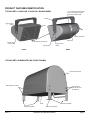
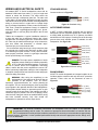
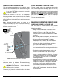
WET X
Premium Quality All-Weather/All-Purpose Loudspeakers
Installation and Operation Manual
Models
12" Full-range two-way: WX-1226 • WX-1264 • WX-1266 • WX-1294 • WX-1296 • WX-1299
15" Full-range two-way: WX-1526 • WX-1564 • WX-1566 • WX-1594 • WX-1596 • WX-1599
Dual 18" Subwoofer: WX-218SDF
WET SERIES • WET X
Important Safety Instructions
Rigging and Electrical Safety
Always follow these basic safety precautions when using or
installing WET X loudspeakers and accessories:
DANGER: The loudspeakers described in this
manual are designed and intended to be ‘flown’ or
suspended using a variety of rigging hardware,
means, and methods. Installation of loudspeakers should
only be performed by trained and qualified personnel. It is
strongly recommended that a licensed and certified
professional structural engineer approve the mounting
design. Severe injury and/or loss of life may occur if these
products are improperly installed! All electrical connections
must conform to applicable electrical codes.
•Read these instructions prior to assembly.
•Keep these instructions for reference.
•Heed all warnings.
•Follow all instructions, particularly those pertaining to
rigging, mounting, hanging and electrical connections.
•Only use attachments and accessories that are
specified and approved by the manufacturer.
•Refer all servicing to qualified service personnel.
The terms caution, warning, and danger may be used in this
manual to alert the reader to important safety considerations.
If you have any questions or do not understand the meaning
of these terms, do not proceed with installation. Contact
your local dealer, distributor, or call Community directly for
assistance. These terms are defined as:
CAUTION: Describes an operating condition or
user action that may expose the equipment or user
to potential damage or danger.
WARNING: Describes an operating condition or
user action that will likely cause damage to the
equipment or injury to the user or to others in the
vicinity.
DANGER: WET X rigging fittings are rated at a
Working Load Limit of 200 lbs (90.7 kg) with a 10:1
safety margin. No single rigging fitting should ever
be subjected to a load that is greater than 200 lbs. Failure to
heed this warning could result in injury or death!
IMPORTANT: Refer to the sections on installation
and connections later in this manual for additional
information on rigging and electrical safety.
DANGER: It is possible to experience severe
electrical shock from a power amplifier. Always
make sure that all power amplifiers are in the
“OFF" position and unplugged from an AC Mains supply
before performing electrical work.
DANGER: Describes an operating condition or
user action that will immediately damage the
equipment and/or be extremely dangerous or life
threatening to the user or to others in the vicinity.
These servicing instructions are for use by qualified service
personnel only. To reduce the risk of fire or electric shock
do not perform any servicing other than that contained in
the operating instructions unless you are qualified to do so.
CAUTION: Installation of WET X loudspeakers should only be performed by trained and qualified personnel. It is strongly
recommended that a licensed and certified professional structural engineer approve the mounting. Severe injury and/or loss
of life may occur if this product is improperly installed.
Page 2
Installation and Operation Manual
WET X
Table of Contents
Important Safety Instructions ������������������������������������������������������������������������������������������������������������������������������������������������2
Introduction����������������������������������������������������������������������������������������������������������������������������������������������������������������������������3
Unpacking and Inspection������������������������������������������������������������������������������������������������������������������������������������������������������4
System Information ���������������������������������������������������������������������������������������������������������������������������������������������������������������4
Product Features Identification����������������������������������������������������������������������������������������������������������������������������������������������5
Rigging / Suspension and Safety ������������������������������������������������������������������������������������������������������������������������������������������6
Installation ����������������������������������������������������������������������������������������������������������������������������������������������������������������������������7
Wiring and Electrical Safety���������������������������������������������������������������������������������������������������������������������������������������������������9
Subwoofer Installation����������������������������������������������������������������������������������������������������������������������������������������������������������10
Final Assembly and Testing��������������������������������������������������������������������������������������������������������������������������������������������������10
Maintaining Weather Resistance������������������������������������������������������������������������������������������������������������������������������������������10
Technical Drawings�������������������������������������������������������������������������������������������������������������������������������������������������������������� 11
Specifications ����������������������������������������������������������������������������������������������������������������������������������������������������������������������14
EC Statement of Conformity������������������������������������������������������������������������������������������������������������������������������������������������15
Warranty Information������������������������������������������������������������������������������������������������������������������������������������������������������������15
Introduction
Thank you for your selection of Community’s WET X Series Loudspeakers.
This manual is intended to help you install and use WET X loudspeakers safely and effectively. It provides useful information
to help you obtain the best performance, sound quality, and reliability from your WET X system. We recommend that you
read the entire manual before beginning your installation.
WET X Features / Technology
WET X Series loudspeakers offer numerous features and technologies that provide unprecedented sonic quality and
installation flexibility. Some of these include:
•Unique two-way, full-range loudspeakers with advanced passive crossover technology
•All models are weather-resistant, suitable for outdoor direct exposure
•All-weather, multi-layer glass composite shell over 18mm (7-layer) marine grade plywood interior
•Protective 304 stainless steel grilles and mounting brackets are covered with a rugged, zinc-rich dual-layer powder-coat
finish for superior resistance to corrosion and appearance changes
•Zinc-rich dual-layer powder-coated 304 stainless steel mounting bracket(s) included
•Stainless steel hardware
•All models are available in black or white; custom colors are also available
•Rotatable horn pattern (in applicable models)
•Large format waveguide delivers excellent pattern control
•1.4" (36 mm) exit / 2.87" (72.2 mm) VC HF compression driver (12-and 15-inch models)
•Available with built-in 400W autoformer for 70.7V / 100V applications
WET X
Installation and Operation Manual
Page 3
Unpacking and Inspection
System Information
Community WET X loudspeakers are engineered and
manufactured to be rugged and they are carefully packed
in sturdy cartons. Make sure that the number of cartons
shown on the freight documents have actually been
delivered. It is wise to thoroughly inspect each unit after it
has been removed from the packaging, as damage could
occur during shipping.
Physical Features / General Description
Please note that once the shipment has left your dealer
location or the Community factory, the responsibility for
damage is always borne by the freight company. If damage
has occurred during shipping, you must file a claim directly
with the freight company. It’s very important to contact the
freight company as soon as possible after receiving your
shipment, as most freight companies have a short time limit
within which they will investigate claims. Be sure to save
the carton and the packing material, as most claims will be
denied if these materials are not retained. Your Community
dealer and the factory will try to help in any way they can,
but it is the responsibility of the party receiving the shipment
to file the damage claim.
It is always a good idea to retain the carton and packing
materials indefinitely, if possible, in the event that the unit
may need to be returned to your dealer or distributor for
repair in the future.
In the Carton
12-INCH and 15-inch models: Each shipping carton
contains the following items:
•One (1) WET X loudspeaker
•One (1) 304 stainless steel zinc-rich dual-layer
powder-coated horizontal mounting bracket
•One (1) operation and installation manual
The WET X family is comprised of two (2) standard models
(12" and 15" two-way models) with six (6) horn pattern
options. There is a standard subwoofer model (dual-18" LF
drivers) available in a down-fire configuration. All models
are available in a standard black or white gel-coat finish
with options for custom colors that can be specially ordered.
The 304SS mounting bracket and grille are color matched
to the cabinet for all models. The hardware and mounts
for the down-fire subwoofer are also color matched to the
enclosure. Hardware required to mount the bracket to the
installation surface must be supplied by the customer.
The 12-inch and 15-inch cabinets are a modified trapezoidal
shape to emulate a traditional wooden enclosure, and have
a rounded rear panel. They are comprised of a fiberglass
outer shell and face that are internally lined and reinforced
with 18mm (7-layer) marine grade plywood. This lining
and reinforcement allows for improved low frequency
performance as well as a stronger, less resonant enclosure.
DANGER: It is essential that a safety cable
(not supplied) be utilized whenever a WET X
Loudspeaker is installed. The safety cable
must be secured to a suitable load-bearing point
separate from the loudspeaker mounting point, with as
little slack as possible so as not to develop undue
kinetic force if the WET X bracket were to fail. The WET X
full-range loudspeakers include a 1/2"-13 mounting
point on the rear of the cabinet for this purpose.
•One (1) warranty card
•Mounting hardware: 1/2"-13 x 2" hex bolts (x3), 1/2"
lock washers (x3), 1/2" flat washers (x3), 1/4" hex
bolts (x2), 1/4" lock washers (x2), 1/4" flat washers
(x2), 2" OD rubber gaskets (x3), and 1/4" rubber
gaskets (x2). Hardware is SS unless otherwise noted.
Subwoofer: Each shipping carton contains the
following items:
•One (1) WET X subwoofer
•One set of four (4) zinc-rich dual-layer powder-coated
steel mounting brackets
•One (1) operation and installation manual
•One (1) warranty card
•Mounting hardware: 1/2"-13 x 2" hex bolts (x8), 1/2"
lock washers (x8), 1/2" flat washers (x8), and 2" OD
rubber flat washers (x8). Hardware is SS unless
otherwise noted.
Page 4
Installation and Operation Manual
WET X
Product Features Identification
Typical WET x 12-inch or 15-inch Full-range Model
1/2"-13 Safety Attachment Point
(user must supply appropriate
fastener and safety cable)
Bracket
Rigging Points
(sides)
Grille
SJOW Input Cable
Gland Nut
Grille Retention Screws (16)
Bracket Angle
Securing Bolt
Bracket slot
Rigging Points
(sides)
Front
Rear
Typical WET X Subwoofer (WX 218SDF shown)
Subwoofer Enclosure
Grille Retention Screws
Rigging Points
(1/2"-13 hex bolts
and washers)
Mounting Brackets
Grille
Mounting Brackets
WET X
Gland Nut and Cable
Installation and Operation Manual
Page 5
Rigging / Suspension and Safety
TERMINOLOGY: The terms “rigging", “flying" and
“suspension" are often used interchangeably to describe
the installation of loudspeaker systems above ground level.
None of these terms pertain to, or attempt to describe, the
actual method that is used (cables, brackets, chains, etc.).
DANGER: The loudspeakers described in this
manual are designed and intended to be suspended
using a variety of rigging hardware, means, and
methods. It is essential that all installation work involving
the suspension of these loudspeaker products be performed
by competent, knowledgeable persons who understand
safe rigging practices. Severe injury and/or loss of life may
occur if these products are improperly suspended.
DANGER: All rigging fittings and inserts must
remain sealed with the included hardware or they
must be fitted with properly rated optional mounting
hardware. Any missing fasteners will compromise the
weather resistance of the enclosure.
COMMUNITY RIGGING HARDWARE WARRANTY:
Community warrants that its loudspeaker systems and
its optional mounting and rigging hardware have been
carefully designed and tested. Community loudspeakers
may be safely suspended when each loudspeaker model
is suspended with Community-manufactured mounting
and rigging brackets specifically designed for use with
that particular model of loudspeaker. This warranty applies
only for use under normal environmental conditions, and
when all loudspeakers, component parts, brackets and
hardware are assembled and installed in strict accordance
with Community’s installation guidelines contained herein.
Beyond this, Community assumes no further or extended
responsibility or liability, in any way or by any means
whatsoever. It is the responsibility of the installer to insure
that safe installation practices are followed, and that such
practices are in accordance with any and all local, state,
federal, or other, codes, conditions, and regulations that may
apply to, or govern the practice of, rigging, mounting, and
construction work in the relevant geographic territory. Any
modifications made to any parts or materials manufactured
or supplied by Community shall immediately void all pledges
of warranty or surety, related in any way to the safe use of
those parts and materials.
Page 6
WARNING
NON-COMMUNITY RIGGING HARDWARE:
Non-Community hardware used for rigging a
WET X loudspeaker must be certified by the supplier
for such use and must be properly rated to maintain an
appropriate design factor (safety margin).
IMPORTANT NOTES ON RIGGING LOUDSPEAKERS
There are three areas of responsibility for rigging
loudspeakers. The first is the building structure. Always
consult with the building architect or structural engineer
to assure the ability of the structure to support the
loudspeaker system. The second area of responsibility is
the loudspeaker itself. Community certifies its loudspeaker
systems and rigging accessories for suspension when they
are properly installed according to our published guidelines.
The third area of responsibility is everything between the
loudspeaker and the building structure and the actual
process of installation. The installing contractor assumes
this responsibility. Loudspeaker rigging should be performed
only by certified rigging professionals using certified rigging
hardware chosen for the specific application. Prior to
installation, the contractor should present a rigging plan,
with drawing and detailed parts list, to a licensed structural
engineer (P.E.) or architect for written approval.
WARNING: WET X rigging fittings are rated at a
Working Load Limit of 200 lbs (90.7 kg) with a 10:1
design factor. No single rigging fitting should ever
be subjected to a load that is greater than 200 lbs. Failure to
heed this warning could result in injury or death!
DANGER: Use the mounting points only as
described above. Do not use them in such a way
as to apply sideways leverage to them. Failure to
follow this instruction could result in immediate failure of the
mounting points resulting in damage to the loudspeaker and
serious injury or death to personnel.
Installation and Operation Manual
WET X
Installation
Before you start
Rigging Bolt
q Read all instructions and gather tools necessary before
starting the installation. Please read all safety instructions
and warnings regarding rigging and installation of the
loudspeaker. The "q" preceding each step can be used to
check off each step as it is completed (or applicable).
Every effort has been made to ensure that the information
contained in this manual was complete and accurate at
the time of printing. However, due to ongoing technical
advances, changes or modifications may have occurred
that are not covered in this publication. The latest version of
this manual is always available at www.communitypro.com.
The revision date can be found on the rear cover.
Mount the Loudspeaker Bracket
The WET X 12-inch and 15-inch loudspeakers are loaded
and shipped with the components in a horizontal orientation.
Attach the bracket to the support structure prior to mounting
the loudspeaker enclosure.
q Determine the bracket location and mount the bracket to
the support structure. Mounting hardware is not included
and should be specified by a structural engineer.
q Mount the bracket with the slot oriented correctly (where
the front of the loudspeaker will be) for later installation of
the bolt to secure the angle. [Bracket above - slot forward,
Bracket behind - slot down]. See Figure 1. Enclosure
Bracket
Bracket Slot
Rigging Bolt
Bracket
Angle Securing Bolt
Enclosure
Bracket Slot
(angles marked)
Figure 1. Orient the slot before mounting the bracket
Note: The loudspeaker is primarily designed to be mounted
horizontally, but can be mounted vertically if desired. Please
consult a structural engineer for the appropriate mounting
mechanism and hardware. [Additional hang points on the
cabinet are available as a configure-to-order option].
Mount the Loudspeaker
q The standard orientation of the loudspeaker is with the
horn on the right side. See Figure 2. If it is necessary for
coverage purposes for the horn to be on the left side, the
grille should be removed, rotated 180°, and reattached
so that the Community logo is at the bottom. There are a
number of screws around the perimeter of the enclosure,
remove them, lift the grille off, rotate it, then replace it and
reattach using all of the screws. All holes must be filled with
the original hardware (or similar approved by Community)
for the enclosure to retain its weather-resistant properties.
Figure 2. Standard horn location (right side)
with logo at bottom of grille
WET X
Installation and Operation Manual
Page 7
Mount the loudspeaker (cont'd)
q Attach the provided 2" gaskets to the inside surface of
the bracket arms. With the adhesive side facing the inside
of the bracket, align with the large hole and press into place.
q Lift the loudspeaker into place between the bracket arms.
Attach the loudspeaker to the bracket using the 1/2"-13
hardware as shown in Figure 3. Repeat for the opposite
side. Tighten bolts to finger tight (enough to hold the speaker
in position).
stated enclosure IP54 rating. There are degree marks on the
outside of the bracket slot to help keep the angle consistent.
Place the provided smaller rubber gasket washers between
the yoke and cabinet and install bolts as shown. Tighten to
finger tight to hold the angle. Fully tighten the hardware (so
cabinet can no longer freely rotate) to ensure that cabinet is
secure and the angle is set.
CAUTION: Over-tightening the hardware can
damage the bolts, threaded inserts, or the cabinet
finish.
q Determine the approximate angle of downward tilt. It
must be at least 5° down from horizontal to maintain the
Rubber gasket (align and adhere adhesive side to bracket)
Bracket
1/2" SS Flat Washer
1/2" SS Lock Washer
Enclosure
1/2"-13 x 2" SS Hex Bolt
1/4"-20 Hex Bolt (secures angle)
1/4" SS Lock Washer
1/4" SS Flat Washer
Rubber Washer
Figure 3. Attach bracket to loudspeaker
Rotating the Horn
While the horn orientation for the HF section of the
WET X loudspeakers is determined when the loudspeaker
is ordered, if it becomes necessary, the horn can be rotated
in the field, offering greater coverage pattern options.
Simply remove the grille and the eight (8) screws mounting
the horn. Being sure not to twist the HF wiring, rotate the
horn 90 degrees and place it evenly back into the cabinet
face. Reinstall the horn screws and the grille assembly (See
Figure 4).
90°
Important: When reinstalling the grill screws, tighten the
screws to finger tight and then add an additional half turn.
Over-tightening may damage or compromise the weatherresistance of the enclosure.
5 x 30 mm Pan Head Screws
Figure 4. To rotate horn - remove screws, carefully pull
horn out, rotate 90°, place horn back in cabinet, and
replace screws.
Page 8
Installation and Operation Manual
WET X
Wiring and Electrical Safety
All standard WET X Series loudspeakers come with an
attached SJOW rated input cable, 12' (4m) in length and
colored to match the enclosure. The cable enters the
enclosure through a waterproof gland nut. The other end
of the cable is un-terminated. Beyond this length, line-loss
calculations should be performed when selecting additional
wiring to prevent losses in output due to voltage drops
due to increased impedance. Please contact Community’s
TAG Team (Technical Applications Group) for additional
assistance (email: [email protected], phone:
(610) 876-3400, or toll-free (800) 523-4934 in the US and
Canada).
q Wire the loudspeaker. A typical installation method is
to bring the cable into a waterproof junction box (J-box)
equipped with a waterproof gland nut. Connections within
the J-box may be made with barrel-type crimp connectors,
wire nuts, solder and heat-shrink, or terminal strips.
Terminate per your local electrical code. We recommend using barrel-type crimp connectors that
are crimped with a forged crimp tool (such as Klein 1005)
or a ratcheting tool (such as Klein T1720), as this method,
when properly executed, results in a gas-tight connection
that is quick and easy to accomplish.
DANGER: The output power capabilities of audio
amplifiers present a danger to installers especially
in 70.7V and 100V distributed systems. To minimize
the risk of electric shock from loudspeaker connecting
cables, confirm that the power amplifiers are turned “off"
before connecting loudspeaker cable(s) to the loudspeaker
or amplifier. Always follow local electrical codes and proper
electrical safety procedures.
WARNING: After wiring the amplifier(s) to the
loudspeaker(s), first power-up all devices that are
upstream of the amplifier, such as mixers,
equalizers, compressor/limiters, etc., before powering-up
the amplifier. This is to avoid passing any clicks or pops that
may originate in the upstream devices to the loudspeakers.
The amplifier should initially be powered-up with its gain
controls turned all the way down. After making sure that a
continuous signal is present, such as a CD playing, slowly
raise the level of the gain controls to establish that the wiring
has been installed correctly. Only then should the
loudspeaker be operated at normal output levels.
Standard Wiring
Connect as shown in Figure 5a.
(–) ( Black)
(+) ( White)
Figure 5a. Standard wiring
Autoformer Wiring
A WET X Series loudspeaker equipped with an optional
autoformer has four selectable power taps. These are set
at 100W, 200W, and 400W on a 70.7V systems, and 200W
and 400W on a 100V system. Choosing one of the four taps
governs how much amplifier power is available for each
loudspeaker. See Figure 5b.
100W ( Red)
200W ( White)
400W
70.7V
400W ( Green)
COM ( Black)
200W ( Red)
400W ( White)
400W
100V
N/A ( Green)
COM ( Black)
Figure 5b. Autoformer wiring
Bi-Amp Wiring
All WET X models designated as bi-amped models do not
include a passive crossover and only offer an HF protection
capacitor. These units can be connected as seen in
Figure 5c.
LF (+) (Red)
LF (–) ( Black)
Bi-Amp
8Ω
HF (+) ( White)
HF (–) ( Green)
Figure 5c. Bi-amp wiring
IMPORTANT: All electrical installation connections for loudspeaker lines are subject to all applicable
governmental building and fire codes. The selection of appropriate electrical hardware to interface with the
WET X loudspeaker lies solely with the installation professional. Community recommends that an appropriately
licensed engineer, electrician, or other qualified professional identify and select the appropriate conduit, fittings, wire,
etc. for the installation.
WET X
Installation and Operation Manual
Page 9
Subwoofer Installation
Final Assembly and Testing
The leg brackets are attached to the subwoofer when
shipped. Remove and discard the hardware holding the
subwoofer to the shipping pallet.
q Attach a safety cable to the attachment point on the
rear of each loudspeaker. The safety cable and (1/2"-13)
attachment hardware are not included. Please consult a
structural engineer for the appropriate cable for the load and
application. The safety cable must be secured to a suitable
load-bearing point separate from the loudspeaker mounting
point, with as little slack as possible, so as not to develop
undue kinetic force if the WET X mounting were to fail.
Do not reuse this hardware to mount the subwoofer
to the floor or structure.
q Mount the subwoofer to the floor. The hole pattern
dimensions are on the technical drawing (page 13).
Anchoring hardware is not provided. Please use hardware
specified by your structural engineer rated for the load and
type of surfacing. Lift the subwoofer into position and secure
to surface.
Note: Additional mounting patterns are offered as a
Configure-to-Order (CTO) option. Consult your Community
representative and structural engineer for the recommended
bracket or mounting system.
2" OD Rubber Washer
Bracket
q Power and test the system.
Maintaining Weather Resistance
GUIDELINES FOR WET X OUTDOOR USE
WET X is suitable for outdoor installation when used as
recommended. For best results in outdoor applications,
follow these guidelines:
•Always orient the loudspeaker so the mouth of the
horn is, at a minimum, pointing at least 5 degrees
downward. Failure to do this could result in water
collecting inside the enclosure under extreme weather
conditions.
•When handling a WET X loudspeaker, be careful not to
scratch or scrape the finish on the grille or enclosure.
•All mounting holes must be sealed off with the
stainless steel bolts, washers, and rubber washers
supplied. If, for any reason, these bolts must be
removed, seal off the hole with silicone caulking or
some other suitable weather-tight sealant.
1/2" SS Lock Washer
1/2"-13 x2"
SS Hex Bolt
•The rubber washers supplied with the mounting bolts
must be placed between the mounting bracket and the
enclosure.
1/2" SS Flat Washer
Figure 6. Bracket attachment to subwoofer
q If it is necessary to remove the leg brackets from the
subwoofer, reserve the hardware and reattach the leg
brackets as shown in Figure 6.
CAUTION: The subwoofer is heavy, adequately
support it or turn it on its side to detach or reattach
brackets and their hardware.
q Connect the Subwoofer as detailed earlier in the wiring
section (page 9).
Page 10
•The gland-nut securing the loudspeaker cable to the
enclosure is sealed at the factory. Do not attempt
to remove this nut or the weather-tight seal will be
broken. If you have to replace the gland-nut, it must be
a weatherproof design. It also must be suitably sealed
to the enclosure with silicone caulk or a comparable
weather-tight sealant.
•The grille assembly is designed to prevent normal and
wind-driven rain from directly entering the mouth of the
loudspeaker. The grille is not designed to withstand
such things as being directly sprayed from a hose or
pressure washer; therefore this should be avoided.
•If you use any hardware in place of hardware provided
with your WET X loudspeaker, it should also be made
of stainless steel.
Installation and Operation Manual
WET X
Technical Drawings
Typical 12-inch 2-way Loudspeaker
4.63" (117 mm)
Center of Gravity
12.90" (327 mm)
Center
of Load
16.0" (406 mm)
1/2"-13 Hang Point
Center of Gravity
1/4"-20 Bracket
Locking Point
15.0"
(381 mm)
30.50" (774 mm)
9.5" (241 mm)
Front
Sides
Center of Gravity
Top of Cabinet
2" (50 mm)
9.14" (232 mm)
17.0" (431 mm)
1/2"-13 Safety Hardware
Insert Point
Back
Top / Bracket
Center Line
12" (305 mm)
8" (203 mm)
Slot 0.41" x 1.59"
(11 mm x 41 mm) Typical
4" (102 mm)
1.31" (33 mm)
1.5" (38 mm)
Ø 0.43" (Ø 11 mm)
(14 places
Ø 0.67"
(Ø 17 mm)
1.5" (38 mm)
2.26" (57 mm)
14.34" (364 mm)
Bracket Hole Dimensions
WET X
Installation and Operation Manual
Page 11
Technical Drawings
Typical 15-inch 2-way Loudspeaker
4.63" (118 mm)
Center of Gravity
1/2"-13 Hang Point
Center of Gravity
15" (381)
19.5" (495 mm)
1/4"-20 Bracket
Locking Point
17.13" (435 mm)
33.63" (854 mm)
Front
11.5" (292 mm)
Sides
12.25" (286 mm)
Top of Cabinet
2.0" (51 mm)
back
Center of Gravity
20.5" (521 mm)
1/2"-13 Safety Hardware
Insert Point
Top / Bracket
Center Line
12" (305 mm)
8" (203 mm)
Slot 0.41" x 1.59"
(11 mm x 41 mm) Typical
4" (102 mm)
1.31" (33 mm)
1.5" (38 mm)
1.5" (38 mm)
Ø 0.43" (Ø 11 mm)
(14 places
Ø 0.67"
(Ø 17 mm)
2.26" (58 mm)
15.84" (402 mm)
Bracket Hole Dimensions
Page 12
Installation and Operation Manual
WET X
Technical Drawings
Typical Subwoofer (WX 218SDF shown)
24.88" (632 mm)
30.76" (781 mm)
Bracket
1/2"-13
Mounting Points
(8 Typical)
3.0" (76 mm)
49.80" (1265 mm)
Sides
Ends
Ø .63" (Ø 76 mm)
(4 places)
18.63" (473 mm)
24.32" (618 mm)
45.71" (1161 mm)
48.0" (1219 mm)
Front
FIELD SERVICE
Any driver or crossover service required is accessed from
the front of the enclosure by removing the front grille and
removal of the LF driver or the horn assembly. Take note
of wiring positions prior to removing any drivers from the
loudspeaker. In order to maintain the weather resistance,
components and assemblies must not remain removed from
the loudspeaker any longer than needed for replacement.
Exposure of internal components to the elements for
extended periods could cause failures and void the warranty
on the loudspeaker.
For warranty repair, contact Community directly at
610-876-3400 or ask us for the location of your nearest
Authorized Service Center.
WET X
FOR MORE INFORMATION AND APPLICATION
ASSISTANCE
For more information on installing and operating your
WET X loudspeaker, please refer to Community’s website at
www.communitypro.com. For application support, service
or warranty information, refer to Community’s website or
contact Community's TAG Team (Technical Applications
Group) for additional assistance at 610-876-3400 or tollfree (US and Canada) at 800-523-4934.
To obtain specific warranty information and available
service locations for countries other than the United States
of America, contact the authorized Community Distributor
for your specific country or region.
Installation and Operation Manual
Page 13
Specifications
MODEL
WX-1226
WX-1264
WX-1266
WX-1294
Loudspeaker Type
2-way, full-range
Driver Complement
LF: 1 x 12" weather-treated cone, HF: 1 x 1.4" exit driver
Coverage Pattern (H x V)
120° x 60°
60° x 40°
60° x 60°
WX-1296
WX-1299
90° x 60°
90° x 90°
90° x 40°
Operating Range (-10 dB)
40 Hz - 22 kHz
Frequency Response
(-3 dB)
63 Hz - 18 kHz
600W RMS, 1200W Program, 69 volts RMS, 138 volts momentary peak
Input Ratings
Sensitivity 1W/1m 97dB (63 Hz–16 kHz) 98dB (63 Hz–16kHz) 98dB (63 Hz–16 kHz) 97dB (63 Hz–16 kHz) 97dB (63 Hz–16 kHz) 97dB (63 Hz–16 kHz)
(Frequency range) 97dB (250 Hz-4 kHz) 99dB (250Hz–4 kHz) 99dB (250 Hz–4 kHz) 97dB (250 Hz–4 kHz) 97dB (250 Hz–4 kHz) 98dB (250 Hz–4 kHz)
Maximum SPL
125dB / 131dB peak
Continuous / Peak
126dB / 132dB peak
126dB / 132dB peak
125dB / 131dB peak
125dB / 131dB peak
125dB / 131dB peak
8 Ohms,
8.5 Ohms @ 160Hz
8 Ohms,
8.2 Ohms @ 160Hz
8 Ohms,
8.1 Ohms @ 160Hz
8 Ohms,
8.5 Ohms @ 160Hz
8 Ohms,
8.2 Ohms @ 160Hz
8 Ohms,
8.3 Ohms @ 160Hz
Yes
N/A
Nominal,
Minimum Impedance
1.5 kHz
Crossover Frequency
Recommended
High Pass Filter:
Horn Rotatable
60Hz 24dB/oct
Yes
Yes
N/A
Yes
12' (4m) SJOW #16 gauge cable (stripped ends)
Input Connection
Two 1/2"-13 points; mounting bracket included; Integral 1/2"-13 Safety Cable Mounting Point
Rigging Provisions
Modified trapezoidal fiberglass outer shell and face lined and reinforced with 18 mm marine grade plywood
Construction
Black or White gel coat fiberglass
Finish
Dimensions: H x W x D
16.0" (406 mm) H x 30.5" (774 mm) W x 17.0" (432 mm) D
Net Weight with bracket
98 lbs (44.5 kg)
MODEL
WX-1526
WX-1564
WX-1566
WX-1594
Loudspeaker Type
2-way, full-range
Driver Complement
LF: 1 x 15" cone, HF: 1 x 1.4" driver
Coverage Pattern (H x V)
120° x 60°
60° x 40°
60° x 60°
90° x 40°
Operating Range (-10 dB)
40 Hz - 22 kHz
Frequency Response
(-3 dB)
50 Hz - 18 kHz
WX-1596
WX-1599
90° x 60°
90° x 90°
600W RMS,1200W Program, 69 volts RMS, 138 volts momentary peak
Input Ratings
Sensitivity 1W/1m 99dB (63 Hz–16 kHz) 98dB (63 Hz–16 kHz) 98dB (63 Hz–16 kHz) 99dB (63 Hz–16 kHz) 98dB (63 Hz–16 kHz) 98dB (63 Hz–16 kHz)
(Frequency range) 98dB (250 Hz–4 kHz) 98dB (250 Hz–4 kHz) 98dB (250 Hz–4 kHz) 98dB (250 Hz–4 kHz) 98dB (250 Hz–4 kHz) 98dB (250 Hz–4 kHz)
Maximum SPL
127dB / 133dB peak
Continuous / Peak
Nominal
Minimal Impedance
8 Ohms,
6.3 Ohms @ 9kHz
126dB / 132dB peak
126dB / 132dB peak
127dB / 133dB peak
126dB / 132dB peak
126dB / 132dB peak
8 Ohms,
8.3 Ohms @ 130Hz
8 Ohms,
8.1 Ohms @ 130Hz
8 Ohms,
8.1 Ohms @ 130Hz
8 Ohms,
8.2 Ohms @ 140Hz
8 Ohms,
6.8 Ohms @ 9kHz
Yes
N/A
1.5 kHz
Crossover Frequency
Recommended
High Pass Filter:
Horn Rotatable
Input Connection
Rigging Provisions
Construction
Finish
50Hz 24dB/oct
Yes
Yes
N/A
Yes
12' (4m) SJOW #16 gauge cable (stripped ends)
Two 1/2"-13 points; mounting bracket included; Integral 1/2"-13 Safety Cable Mounting Point
Modified trapezoidal fiberglass outer shell and face lined and reinforced with 18 mm marine grade plywood
Black or White gel coat fiberglass
Dimensions: H x W x D
19.5" (495 mm) H x 33.63" (854 mm) W x 20.5" (520 mm)
Net Weight with bracket
133 lbs (60.3 kg)
Page 14
Installation and Operation Manual
WET X
Warranty Information
Specifications
MODEL
WX-218SDF
Loudspeaker Type
Subwoofer
(down-fire)
Driver Complement
LF: 2 x 18" weather-treated cone
Coverage Pattern (H x V)
360° x 180°
Operating Range (-10 dB)
35 Hz - 500 Hz
Frequency Response
(-3 dB)
47 Hz - 450 Hz
Input Ratings
1400W RMS,
2800W Program
74.8 volts RMS,
149.7 volts momentary peak
TRANSFERABLE WARRANTY “(LIMITED)" VALID
IN THE USA ONLY
The WET X Loudspeakers are designed and backed by
Community Professional Loudspeakers. For complete
warranty information within the USA please refer to the
Warranty Card enclosed with the product. Please call 610876-3400 to locate your nearest Authorized Field Service
Station. For Factory Service call 610-876-3400. You must
obtain a Return Authorization (R/A) number prior to the
return of your product for factory service.
WARRANTY INFORMATION AND SERVICE FOR
COUNTRIES OTHER THAN THE USA
Sensitivity 1W/1m
(free space SPL)
103dB (50 Hz - 315 kHz) half space
Maximum SPL
Continuous / Peak
134dB (140dB peak)
To obtain specific warranty information and available
service locations for countries other than the United States
of America, contact the authorized Community Distributor
for your specific country or region.
Nominal
Minimal Impedance
4 Ohms,
3.3 Ohms @ 40 Hz
Shipping Damage / claims
Input Connection
Rigging Provisions
3' (0.914m) SJOW #10-2 gauge cable
(stripped ends)
Four pair (8) 1/2"-13 points;
mounting brackets included
Modified trapezoidal fiberglass outer
Construction shell and face lined and reinforced with
18 mm marine grade plywood
Finish
Dimensions: Height
Width
Depth
Net Weight with brackets
Black or White gel coat fiberglass
30.76" (781 mm) on brackets
49.8" (1265 mm)
24.32" (618 mm)
If the product is damaged during transit you must file a
damage claim directly with the freight company. It’s very
important to contact the freight company as soon as possible
after receiving your shipment, as most freight companies
have a short time limit within which they will investigate
claims. Be sure to save the carton and packing materials,
as damage claims can be denied if these materials are not
retained. If evidence of physical damage exists upon arrival,
be cautious before signing the delivery acceptance receipt.
Often, the fine print will waive your right to file a claim for
damage or loss after you sign it. Make sure that the number
of cartons shown on the freight documents have actually
been delivered.
196 lbs (88.9 kg)
EC Statement of Conformity
This document confirms that the range of products of Community Professional Loudspeakers bearing the CE label meets
all of the requirements in the EMC directive 89/336/EEC laid down by the Member States Council for adjustment of legal
requirements. Furthermore, the products comply with the rules and regulations referring to the electromagnetic compatibility
of devices from 30-August-1995.
The Community Professional Loudspeaker products bearing the CE label comply with the following harmonized or national
standards: DIN EN 55013:08-1991, DIN EN 55020:05-1995, and DIN EN 55082-1:03-1993.
The authorized declaration and compatibility certification resides with the manufacturer and can be viewed upon request.
The responsible manufacturer is the company:
Community Light & Sound
333 East Fifth Street, Chester, PA 19013 USA
Phone: (610) 876-3400 • Fax: (610) 874-0190
Chester, PA USA May 2013
WET X
Installation and Operation Manual
Page 15
WET X
Premium Quality All-Weather/All-Purpose Loudspeakers
Note: Every effort has been made to insure that the information contained in this manual was complete and accurate at the time of printing. However, due to ongoing technical
advances, changes or modifications may have occurred that are not covered in this manual. Visit Community at www.communitypro.com for the latest version of this manual
and the most recent product information.
©2013 Community Professional Loudspeakers
Community Professional Loudspeakers
333 East Fifth Street, Chester, PA 19013-4511 USA
Phone: (610) 876-3400 • Fax: (610) 874-0190
www.communitypro.com
Part#: 112634 v:10JUN2013