1
IMPORTANT
THIS ENVELOPE CONTAINS YOUR
INSTRUCTIONS AND WARRANTY
Please read carefully before operating your equipment
KEEP FOR FUTURE REFERENCE
WARRANTY NOT VALID UNLESS ENCLOSED CARD
MAILED WITHIN ONE WEEK TO MciNTOSH LABORATORY
mtlntnshLaboratory, Inc.
2 CHAMBERS STREET
Phone 3-5491
BINGHAMTON, N. Y.
EXPORT DIVISION: 25 WARREN ST., NEW YORK, N. Y. CABLE: SIMONTRICE
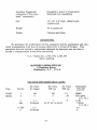
INSTRUCTION MANUAL
MciNTOSH MODEL Me-3D
3D WATT POWER AMPLIFIER
Type A-116B
MciNTOSH LABORATORY, INC.
2 Chambers St.
Binghamton, N. Y.
U.S.A.
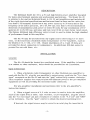
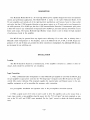
DESCRIPTION
The McIntosh Model Mc-30 is a 30 watt high fidelity power amplifier designed
for home entertainment systems and professional applications. The Model Mc-30
is similar to the earlier McIntosh Model A-116 30 watt amplifiers and includes all
of the rigid electrical specifications and features found in these earlier units plus:
less than 0.3% harmonic distortion at any power output up to 30 watts and at any
frequency in the audio spectrum, 20 to 20,000 cps; less than 0.5% intermodulation
distortion if instantaneous peak power is below 60 watts for any combination of frequencies 20 to 20, 000 cps; and noise and hum level 90 db or more below rated output.
The famous McIntosh high efficiency output circuit is used to obtain the high standard
of performance found in this amplifier.
The Mc-30 may "be operated from any signal source delivering 0.5 or more
volts, or directly from a McIntosh Audio Compensator or Pre-Amplifier, such as
the Models C-S, C-104, or C-10S. Output impedances of 4, Sand 16 ohms are
provided for direct connection to loudspeakers. An additional 600 ohm output is
present for use with lines, etc.
INST ALLA TION
Location
The Mc-30 should be located in a ventilated area. If the amplifier is housed
in a cabinet or other enclosure, holes should be provided for air circulation.
Input Connections
1. When a McIntosh Audio Compensator or other McIntosh pre-amplifier is
used with the Mc-30, plug the pre-amplifier's output-power cord into the "Pre-Amp
input" receptacle on the Mc-30 and turn the "gain" control fully counter clockwise.
This receptacle supplies the required plate and filament power to the pre-amplifier
equipment as well as providing the necessary audio connection.
For pre-amplifier installation and operation refer to the pre-amplifier's
instruction manual.
2. When a signal source of O. 5 volts or more is used to drive the amplifier,
such as the output from a tuner, tape recorder, or pre-amplifier, plug the source
into the "0.5 volt input" pin jack receptacle or connect to the "0.5 volt" and "GND"
screw terminals. Use the "gain" control to obtain the desired operating level.
If desired, the signal source may be wired to an octal plug for insertion in
-1-
the octal "Pre-Amp input" receptacle. In this case connect the input lead to pin #5
and the ground lead to pin # 1. When using this connection the source must not have
a DC 6utput component.
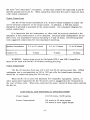
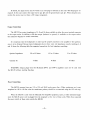
Output Connections
The Mc-30 has output impedances of 4, 8 and 16 ohms available at either the
screw terminal connector or the output socket. In addition, a 600 ohm output
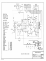
(balanced to ground) is available at the output socket. See schematic diagram for
socket connections.
It is important that the loudspeaker or other load be properly matched to the
amplifier if best performance is to be obtained. Because many loudspeakers do not
have voice coil impedances exactly matching 4, 8 and 16 ohms, the following table
lists suggested connections for best impedance matching.
Speaker Impedance
3. 2 to 6. 5 ohms
6.5 to 13 ohms
4 ohms
Connect To
13 to 32 ohms
8 ohms
16 ohms·
WARNING: Output plugs wired for McIntosh 20W-2 and 50W-2 amplifiers
must not be used with the Mc-30 without rewiring the plug.
Power Connections
The Me-30 operates from any 110 to 130 volt 50-60 cycles power line. (When
continuous use is contemplated on 120 to 130 line volts the transformer primary
should be re-connected using the 125 volt tap. )
When the Mc-30 is used with McIntosh Pre-Amplifier equipment, tuners, or
other associated equipment the Mc-30 power cord is plugged into the receptacle at
the rear of these units. When thus connected the power switch of these units controls
the Mc-30.
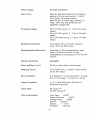
ELECTRICAL AND MECHANICAL SPECIFICATIONS
Power Supply
117/125 volts, 50/60 cycles
Power Consumption
135 watts at 30 watts output
105 watts at zero signal output
-2-
Power Output
30 watts continuous
Input Level
Input # 1 (pin jack and screw terminals
and pin 5 of pre amp socket) .5 volts
to 30 volts, with gain control
Input #2 (pin 2 of pre amp socket) 2.5
volts, (For use with McIntosh preamplifier equipment).
Frequency Range
20 to 30, 000 cycles + . 1 db at 30 watts
output
15 to 50,000 cycles + .5 db at 30 watts
output
10 to 100,000 cycles ~ 1 db at 15 watts
output
Harmonic Distortion
Less than 1/3% at 30 watts output or
less, 20 to 20,000 cycles.
Intermodulation Distortion
Less than 1/2.0/0 if ins tantaneous peak
power is below 60 watts for any
combination of frequencies 20 to 20,000
cycles.
Impulse Distortion
Negligible
Noise and Hum Level
90 db or more below rated output
Damping Factor
12 or better for 4, 8 and 16 ohm output,
16 for 600 ohms
Input Impedance
0.5 meg for 0.5 volt input and 0.13 meg
for 2.5 volt input. 20 cycles to 40 Kc
Output Impedance
4, 8, 16 and 600 ohms (600 ohm is
balanced to ground)
Phase Shift
20 cycles 3 0
20,000 cycles gO
Tube Complement
Pre-Amp:
12AX7
Phase Inverter:
12AU7
Voltage Amp:
12BH7
Driver:
12AX7
Output:
2 - 1614
Rectifier:
5U4-GA
-3-
Auxiliary Equipment
connection ("Pre-Amp
input" receptacle)
Designed to power C -8 and other
Mclntosh Pre-Amplifiers
Size
13" x 8" x 8" high, chassis type
construction
Weight
30.5 pounds net
Finish
Chrome and Black
GUARANTEE
We guarantee the performance of this equipment and the mechanical and electrical workmanship to be free of serious defects for a period of 90 days. This
guarantee does not extend to components damaged by improper use nor does it
extend to transportation to and from the factory.
U. S. Patents No.2, 477,074; 2,646,467
others pending
McINTOSH LABORATORY INC.
2 Chambers Street
Binghamton, N. Y., U. S. A.
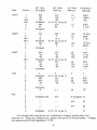
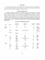
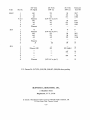
VOLTAGE AND RESISTANCE CHART
Tube
12AX7
(input)
Pin No.
DC Volts
No Signal
DC Volts
30Wout
AC Volts
30Wout
1
2
120
0
102
0
1.5
.42
3
4&5
1.1
Filament
1
(6. 3V AC to pin 9)
.4
6,7&8
9
Filament
Resistance
Unit Off
380K*
27K (gain
C.C.W.)
3.3K
o (hum
C.C. w.)
0
-4-
Tube
12AU7
12BH7
12AX7
1614
5U4
Pin No.
DC Volts
No Signal
DC Volts
30Wout
1
2
3&8
4&5
6
7
9
240
120
129
Filament
240
96
Filament
210
102
108
(6. 3V AC to pin 9)
210
86
10
1.5
.5
40K*
380K*
18K
10
0
40K*
2.5K*
1
2
3&8
4&5
6
7
9
352
0
18
Filament
352
0
Filament
295
0
15.5
(6. 3V AC to pin 9)
295
0
132
10
.4
12.2K*
220K
1.2K
132
10
12.2K*
220K
1
2
3
4&5
6
7
8
9
440
-42
-42
Filament
440
-42
-42
Filament
375
-41
-42
(6. 3V AC to pin 9)
375
-41
-42
98
132
132
205*
101M
150K
98
132
132
205*
101M
150K
1
2
3
4
5
6
7
8
0
Filament
440
440
-42
0
(6.3V AC to pin 7)
375
375
-42
0
0
98
98
132
205*
205*
150K
19
1
2
3
4
5
6
7
8
AC Volts
30Wout
Resistance
Unit Off
Filament
.8
5.5
98
Filament 460
410
8.8(ripple) 0*
Filament
(5.0V AC to pin 2)
370
44
370
44
0*
All voltages and resistances are measured to chassis except those with
asterisk (*). These are measured to chassis with pin #2 of 5U4 grounded. Voltages
are measured with high impedance VTVM.
-5-
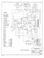
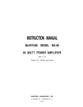
PRE-AMP. INPUT
OUTPUT
TO
FIL.
NOTE I
output Connections
Using Octal Socket
4 ohms
8 ohms
-
pins
pins
and 2
and 3
16 ohms - pins
and 4
600 ohms - pins 7 and 8
(pin 6 is CT and ground)
70.7 volts - pins 5 and 6
(pin 6 is ground)
Pre-Amplifier Input
M-150B
Socket Connections
Pin 1 _ ground
Pin 2 - pre-amp input (2. 5V)
Pin 3 - not used
Pin 4 - +310V at 3.5 rna,
Pin 5 -
.5v input
Pin 6 - not used
Pins 7 and 8 - 6.3V at 1 amp.
Note 1 - This Jumper strap
may be removed if ungrounded
low impedance outputs are
desired,
Rl
SOOK Pot., Gain AdJ.
R2
R3
R5
RS
R7
R8
R9
lOOK
27K
3.3M
3.3K
68 ohms
lOOK
330K
680K
RIO
18K, lW
R4
I
Rll
R12
1.2M
1M
Rl3
2.2K, 5%
R14
R15
R16
R17
RIB
27K, 5%
30K, 5%
220K
1.2K
220K
RI
GAIN
5%
RI3
RIg
12K, 2W*
R20
R21
R22
R23
12K, 2W*
120K, 5%
1M
820K, 5%
U4
~
m
R2S
R26
220K
220K
C4
C5
R27
U28
R29
10K, lOW
150 ohm lOW
250 ohm Pot.
C6
C7
C8
R30
R31
R32
R33
R34
R3S
3.3K
2.2M
330K
220K
220K
180K
C9
Cl0
Cll
C12A
C128
C12C
*Matched to within 1%
Cl
C2
CI3
.1mf, 400V
.47mf, 2QOV
lOOmf, 12WV
.22mf, 400V
.22mf, 400V
.lmf, 400V
470mmf, 500V
• 047mf, 600V
• 047mf, 600V
• 25mf, 600V
.25mf, 600V
40mf, 500V
80mf, 450V
20mf, 450V
lOmf J 450V
R27
R28
f'2C }12B I'2A
~
JI3
R29
-=-
TOFIL.
HUM ADJ.
TO FIL.
MciNTOSH LABORATORY, INC.
SERIAL NOS. 15329 AND ABOVE
J.W.C.
DATE:
5-15-56
MODEL MC-30, TYPE A-IIS8, POWER AMPLIfiER
MC-30-4
M·l 2.5 47
marrant,
Mcintosh Laboratory warrants the electrical and mechanical workmanship and components of this equipment to be free of serious defects for 'a period of 90 days provided the enclosed
warranty card is duly completed and returned to Mcintosh Laboratory.
Mcintosh Laboratory further warrants the transformers supplied as components of this
equipment to be free of manufacturing defects for a period of 1 year from the date of shipment
from the factory. Mcintosh Laboratory will replace at no charge any such transformer failing to
meet this warranty period.
This warranty does not extend to components or transformers damaged by improper use,
nor does it extend to transportation to and from the factory.
-R~ H.1'h t c:a-n-hr3~ ·
mtlnto.sh Laboratory, Inc.
2 CHAMBERS ST.
©GOES MBO
BINGHAMTON, NEW YORK
INSTRUCTION MANUAL
MciNTOSH MODEL Me·30
30 WATT POWER AMPLIFIER
Type A-116B
Serial
# 15329 and Over
i
MciNTOSH LABORATORY, INC·
2 Chambers St.
Binghamton, N. Y.
U.S.A.
1.5M-757-HPB
DESCRIPTION
The McIntosh Model MC-30 is a 30 watt high fidelity power amplifier designed for home entertainment
systems and professional applications. The Model MC-30 is similar to the earlier McIntosh Model A-116
30 watt amplifiers and includes all of the rigid electrical specifications and features found in these earlier
units plus: less than 113% harmonic distortion at any power output up to 30 watts and at any frequency in
the audio spectrum, 20 to 20,000 cps; less than 112% intermodulation distortion if instantaneous peak power
is below 60 watts for any combination of frequencies 20 to 20,000 cps; and noise and hum level 90 db or more
below rated output. The famous McIntosh high efficiency output circuit is used to obtain the high standard
of performance found in this amplifier.
The MC-30 may be operated from any signal source delivering 0.5 or more volts, or directly from a
McIntosh Audio Compensator or Pre-Amplifier, such as the Models C-8, C-4, C-104, or C-108. Output impedances of 4, 8 and 16 ohms are provided for direct connection to loudspeakers. An additional 600 ohm output is present for use with lines, etc.
INSTALLATION
Location
The MC-30 should be located in a ventilated area. If the amplifier
closure, holes should be provided for air circulation.
IS
housed
III
a cabinet or other en-
Input Connections
1. When a McIntosh Audio Compensator or other McIntosh pre-amplifier is used with the MC-30, plug
the pre-amplifier's output-power cord into the "Pre-Amp input" receptacle on the MC-30 and turn the "gain"
control fully counter clockwise. This receptacle supplies the required plate and filament power to the preamplifier equipment as well as providing the necessary audio connection.
For pre-amplifier installation and operation refer to the pre-amplifier's instruction manual.
2. When a signal source of 0.5 volts or more is used to drive the amplifier, such as the output from a
tuner, tape recorder, or pre-amplifier, plug the source into the "0.5 volt input" pin jack receptacle or connect to the "0.5 volt" and "GND" screw terminals. Use the "gain" control to obtain the desired operating
level.
-2-
If desired, the signal source may be wired to an octal plug for insertion in the octal "Pre-Amp input" receptacle. In this case connect the input lead to pin #5 and the ground lead to pin # 1. When using this connection the source must not have a DC output component.
Output Connections
The MC-30 has output impedances of 4, 8 and 16 ohms available at either the screw terminal connector
or the output socket. In addition, a 600 ohm output (balanced to ground) is available at the output socket.
See schematic diagram for socket connections.
It is important that the loudspeaker or other load be properly matched to the amplifier if best performance is to be obtained. Because many loudspeakers do not have voice coil impedances exactly matching 4, 8
and 16 ohms, the following table lists suggested connections for best impedance matching.
Speaker Impedance
Connect To
3.2 to 6.5 ohms
6.5 to 13- ohms
13 to 32 ohms
4 ohms
8 ohms
16 ohms
WARNING: Output plugs wired for Mcintosh 20W-2 and 50W-2 amplifiers must not be used with
the MC-30 without rewiring the plug.
Power Connections
The MC-30 operates from any 110 to 130 volt 50-60 cycles power line. (When continuous use is contemplated on 120 to 130 line volts the transformer primary should be re-connected using the 125 volt tap.)
When the MC-30 is used with the Mcintosh Pre-Amplifier equipment, tuners, or other associated equipment the MC-30 power cord is plugged into the receptacle at the rear of these units. When thus connected
the power switch of these units controls the MC-30.
-3-
GUARANTEE
We guarantee the performance of this equipment and the mechanical and electrical workmanship to be
free of serious defects for a period of 90 days. This guarantee does not extend to components damaged by improper use nor does it extend to transportation to and from the factory.
SERVICE INFORMATION
All Mcintosh equipment IS designed for long trouble free operation. All components are of highest
quality and are conservatively operated. If trouble develops the amplifier may be serviced by your franchised
dealer, a competent serviceman, or returned to the factory. Equipment will not be accepted at the factory
unless factory return authorization is first received. The following chart of operating voltages and resistances
is offered as a guide for servicing the unit. All voltages and resistences are measured to chassis except
those with asterik (*). These are measured to chassis with pin #2 of either 5U4GA grounded. Voltages are
measured with high impedence VTVM. NOTE-UNIT MUST BE TURNED OFF WHEN MEASURING
RESISTENCES.
VOLTAGE AND RESISTANCE CHART
DC Volts
No Signal
DC Volts
30W out
1
2
120
102
-e-
--e--
3
4&5
1.1
Filament
1
(6.3V AC to pin 9)
.4
6,7 & 8
9
Filament
210
102
108
(6.3V AC to pin 9)
210
86
10
1.5
Tube
Pin No.
12AX7
(input)
12AU7
1
2
3 & 8
4&5
6
7
9
12BH7
1
2
3 & 8
4 & 5
6
240
120
129
Filament
240
96
Filament
295
352
--e--
-e--
18
Filament
352
15.5
(6.3V AC to pin 9)
295
7
--a-
9
Filament
--a-
--4-
AC Volts
30Wout
1.5
.42
.5
Resistance
Unit Off
380K*
27K (gain
C.C.W.)
3.3K
-B-(hum
C.C.W.)
40K*
380K*
18K
40K*
2.5K*
132
10
.4
12.2K*
220K
1.2K
132
10
12.2K*
220K
Tube
Pin No.
DC Volts
No Signal
12AX7
1
2
3
4&5
6
7
8
9
440
-42
-42
Filament
440
-42
-42
Filament
1
2
3
4
5
6
7
8
-GFilament
440
440
-42
1614
5U4
1
2
3
4
5
6
7
8
DC Volts
30Wout
375
-41
-42
(6.3V AC to pin 9)
375
-41
-42
-G-
(6.3V AC to pin 7)
375
375
-42
Filament
.8
5.5
Filament 460
Filament
410
AC Volts
SOW out
98
132
132
98
132
132
-f}-
98
98
132
205*
l.lM
150K
205*
l.lM
150K
-G-
205*
205*
150K
98
19
8.8 (ripple)
0*
370
44
370
44
(5.0V AC to pin 2)
U. S. Patents No. 2,477,074; 2,545,788; 2,646,467; 2,654,058 others pending
McINTOSH LABORATORY, INC.
2 Chambers Street
Binghamton, N. Y., U.S.A.
In Canada: Manufactured Under License by McCurdy Radio Industries, Ltd.
22 Front Street West, Toronto, Canada
-5-
Resistance
Unit Off
0*
PRE-AMP. INPUT
OUTPUT
.5V INPUT
TO
FIL.
NOTE I
output Connections
Using Octal Socket
4 ohms
- pins
and 2
8 ohms
- pins 1 and 3
16 ohms - pins 1 and 4
600 ohms - pins 7 and 8
(pin 6 is CT and ground)
70.7 Volts - pins 5 and 6
(pin 6 is ground)
Pre-Amplifier Input
Socket Connections
M-150B
Pin 1 - ground
Pin 2 - pre-amp input (2.5V)
Pin 3 - not used
Pin 4 - +3l0V at 3.5 lOa.
Pin 5 - .5v input
Pin 6 - not used
Pins 7 and 8 - 6.3V at 1 amp.
Note 1 - This jumper, strap
may be removed if ungrounded
low impedance outputs are
desired.
Rl
500K Pot., Gain Adj.
R2
R3
R4
R5
lOOK
27K
3.3M
3.3K
R6
68 ohms, 5%
R7
R8
R9
R10
Rll
R12
R13
R14
R15
R16
R17
R18
lOOK
330K
680K
18K, 1W
1.2M
1M
2.2K, 5%
27K, 5%
30K, 5%
220K
1.2K
220K
R19
R20
R21
12K, 2W*
12K, 2W*
120K, 5%
R22
R23
R24
R25
R26
1M
820K, 5%
1M
220K
220K
C1
C2
C3
C4
C5
R27
C6
C7
R29
10K, lOW
150 ohm lOW
250 obm Pot.
R30
R31
R32
R33
R34
R35
3.3K
2.2M
330K
220K
220K
180K
C9
ClO
Cll
C12A
C12B
C12C
R28
*Ma tcbed to wi tbJ.n 1%
RI
GAIN
R~
\~,------~--------------------~------------r-----~
C8
C13
.lmf, 400V
.47mf, 200V
lOOmf J 12WV
.22mf, 400V
• 22mf , 400V
.1mf, 400V
470mmf, 500V
.047mf, 600V
• 047mf, 600V
• 25mf, 600V
.25mf, 600V
40mf, 500V
80rnf, 450V
20mf, 450V
10mf J 450V
R27
f'2C
R28
}12B
112A
Jcl3
~
R29
-=-
TOFIL .
HUM ADJ.
TO FIL.
MCiNTOSH LABORATORY, INC.
SERIAL NOS. 15329 AND ABOVE
J.W.C.
5-15-56
MODEL MC-30, TYPE A-116B, POWER AMPLifiER
DItAWING NUM ... R
MC-30-4
M-l 2.5 47