1
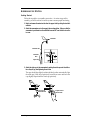
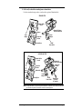
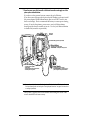
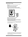
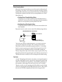
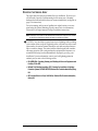
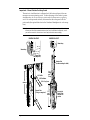
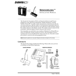
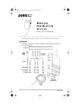
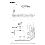
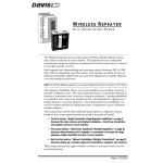
WIRELESS WEATHER STATION
INSTALLATION MANUAL
This manual covers installation of the wireless weather station. Some features discussed (such as barometric pressure and humidity) are only available with the Wireless Weather Monitor II®. This manual also shows
installation with the solar power option, which may not be included in
your wireless weather station. Other manuals included with the station
cover the operation and maintenance of the console and sensors.
C OMPONENTS
The wireless weather station includes the following components. Please
make sure you have everything you need before beginning.
Anemometer
5/16" Flat Washers
5/16" Lock Washers
5/16" Hex Nuts
Extension
Tube
Weather Station Console
Wind Cups
1-1/8"
Saddles
5/16" x 1-1/2"
U-Bolt
5/16" x 3"
Lag Screws
This hardware
comes installed
on Sensor Array:
#12 x 1-1/2"
Pan Head Screw
Power Adapter
#12 Lock Washer
#12 Hex Nut
5/16"
Flat Washers
Cable
Tie
Rain
Collector
2nd Power Adapter
(not supplied with
solar-powered
stations)
#8 x 3/4"
Pan Head Screws
(for mounting Console)
Field Case
3 Volt Lithium
Transmitter Battery
(not supplied with
solar-powered
stations)
Sensor Array
Allen
Wrench
Debris Screen
(place inside
Rain Collector Cone
after installation)
Product # 7425W, 7425WM, 7425WS, 7425WSM, 7440W, 7440WM, 7440WS, 7440WSM
T OOLS
AND
M ATERIALS N EEDED
In addition to the components listed above, you may need some of the following tools and materials.
✦ Flat-Bladed Screwdriver
✦ Phillips Screwdriver
✦ Adjustable Wrench
✦ Wire Cutter or Scissors
✦ Pencil or Other Pointed Object
I NSTALLATION S TEPS
This manual takes you through the step-by-step process of installing your
weather station. These steps are indicated below, along with their page numbers for easy reference:
✦ Assemble and test the station, page 3
✦ Detach the extension tube, page 3
✦ Attach the anemometer, page 3
✦ Attach the wind cups, page 3
✦ Snip the cable tie in the rain collector, page 4
✦ Apply power to the console, page 4
✦ Apply power to the sensor array, page 6
✦ Check that the console is working properly, page 7
✦ Choose locations for the sensor array and console, page 7
✦ Test the proposed locations, page 8
✦ Set dip switches to control ID code and operating mode, page 9
✦ Mount the sensor array, page 11
✦ Secure the sensor array and re-apply power, page 13
✦ Mount the console, page 13
If, once installed, you encounter any problems with the station, please refer to
the troubleshooting guide on page 14.
Page 2
Wireless Weather Station
A SSEMBLING
THE
S TATION
Getting Started
Follow the steps below to assemble your station. At various stages of this
assembly, you will be advised to test the system to ensure proper functioning.
1. Detach and remove the extension tube from the support tube by cutting the two black
cable ties.
2. Attach the anemometer arm to the support tube as shown below. Make sure that the
anemometer is positioned over the white field case and NOT over the black rain collector cone.
Anemometer
Anemometer Arm
Anemometer
Cable
#12 x 1-1/2"
Screw
Support Tube
Lock
Washer
Hex
Nut
Cable Tie
3. Attach the wind cups to the anemometer by pushing the wind cups onto the shaft as
far as they will go, then tightening the set screw.
The cups should drop slightly and into the ideal position automatically. Spin
the wind cups. If they do not spin freely, loosen the set screw and lower the
cups slightly. Repeat until the wind cups spin freely.
a. Push cups onto
stainless steel shaft
Assembling the Station
b. Tighten set screw
with allen wrench
Page 3
4. Prepare the rain collector for use.
Detach the black rain collector cone from its base by rotating the cone
counter-clockwise until its latches line up with the latch openings in the base
and then lift the cone off. (The cone fits tightly and may require extra pressure to remove it the first time.) Carefully cut and remove the black cable tie
which holds the bucket in place during shipping.
Twist off the rain collector cone.
Snip the black cable tie.
Do not re-attach the rain collector cone at this point; you will need to test the
tipping bucket before you complete the installation.
5. Apply power to the station console.
To power up the console, first remove the console’s mounting base by pressing down on the large tab between the two oblong holes on the base’s
underside and pulling the base free. Plug the power adapter into the center
“Power” slot, as shown in the following figure, and then plug the other end
into a 110 VAC outlet.
Once power is applied, the console should beep three times within 20 seconds if the console and receiver are working properly. (Or, if you have the
optional WeatherLink® installed, listen for four beeps within 30 seconds.)
Note: If you are going to use a battery as backup, make sure that you plug in the AC power before
installing the battery. Powering up the console with the battery alone may cause the console to
lock up due to insufficient power.
Page 4
Wireless Weather Station
6. If all is well, re-attach the mounting base as shown below.
Use the standard setup unless you have the optional WeatherLink.
STANDARD SETUP
Weather Station
Console
To
Power
Adapter
SensorLink Receiver
(inside Console Base)
Antenna
Power
Adapter
SensorLink
Receiver
Mounting Base
110 VAC
Power Outlet
WEATHERLINK SETUP
Weather Station
Console
WeatherLink
(inside Console Base)
SensorLink
Receiver
SensorLink
Receiver
To
Power
Adapter
WeatherLink
Power
Adapter
Mounting Base
110 VAC
Power Outlet
WeatherLink
Connection
to Computer
Note: As illustrated above, if you are using the WeatherLink in addition to the SensorLink Receiver,
you will need to position the receiver outside the mounting base.
Assembling the Station
Page 5
7. Open the sensor array field case with a flat-bladed screwdriver and apply one of the
power options indicated below.
If you have a solar-powered system, connect the gel cell battery.
If you have a non-solar-powered system, decide whether you want to install
the power adapter OR the lithium battery (the two will NOT work in tandem or as backup). Davis recommends the battery to ensure power during
storms. If used as the primary power source, one fresh lithium battery
should provide about six months of service. Use two fresh lithium batteries
to double life (second is not provided).
SensorLink
Transmitter
2nd Lithium Battery (optional, not provided)
Lithium Battery
* Provided with non-solar systems
* RECOMMENDED - reliable power during storms
Gel Cell Battery
Power
Plug
* Provided with solar systems
* Rechargeable
* Recommended for solar-powered stations
* Reliable power during storms
Power Adapter
* Provided with non-solar systems
* NOT RECOMMENDED for use during storms power outages will disrupt data collection
Note: Be sure dip switch #4 is set to “Run” (rather than “Test”) so that the LED indicator will not
flash unnecessarily when not testing see “Testing Proposed Locations” on page 8 for instructions
on setting dip switches).
Once power is applied, the console should start reading the values of the
sensors installed in the sensor array.
Page 6
Wireless Weather Station
8. Check all of the readings on your display to be sure they appear correctly (i.e., not
“dashed out”).
Consult your Monitor or Wizard owner’s manual for instructions on displaying the various readings. Spin the wind cups, move the wind vane, and
tip the rain bucket to verify wind speed and direction and rainfall readings.
Note that some readings (e.g., wind direction, barometer, and 0.2 mm rain
collectors) must be calibrated in order to read correctly; calibration instructions are contained in the Monitor or Wizard owner’s manual.
If the console is having problems reading the outdoor sensors, consult the
troubleshooting guide at the end of this manual. If the problem is with the
inside temperature, inside humidity or barometer, consult the Monitor or
Wizard owner’s manual.
9. Re-attach the rain collector cone and lay the debris screen “feet-down” over the
cone’s funnel hole.
C HOOSING L OCATIONS
FOR THE
S ENSOR A RRAY
AND
C ONSOLE
The range of the radio transmission depends on several factors. Try to position the sensor array and console as close together as possible for best results.
Typical maximum ranges:
✦ Line of Sight: 400 feet (120 m)
✦ Through Walls and Ceilings: 100 to 200 feet (30 to 60 m)
✦ Through Trees and Foliage: 100 to 200 feet (30 to 60 m)
As you position your sensor array, try to avoid possible obstructions of rain
and wind—look out for trees and nearby buildings. For roof mounting, and for
ease of installation in other locations, we recommend using the optional
Mounting Tripod (contact Davis for more information).
As you position your console, be aware of possible interference from cordless
phones and other items. To prevent interference, maintain a distance of 10 feet
between the console and the cordless phone (handset and base). Also, for best
reception, avoid positioning the console near large metallic surfaces (e.g., most
refrigerator surfaces).
Choosing Locations for the Sensor Array and Console
Page 7
T ESTING P ROPOSED L OCATIONS
Test your proposed console and sensor locations to ensure successful data
transmission.
1. Temporarily place the sensor array where you plan to mount it.
2. Apply power to the sensor array (see step 7 on page 6).
3. Set dip switch #4 on the transmitter to the TEST position, as shown below.
This puts the transmitter in Test Mode—the Indicator LED will flash to indicate that the sensor unit is transmitting.
Dip Switches
UNIT ID
TEST
S1
Indicator
LED
ON
1 2 3 4
RUN
SensorLink
Transmitter
4. Temporarily place the console where you plan to mount it.
5. Apply power to the console (see step 5 on page 4).
6. Flip dip switch #4 on the receiver to the position opposite its starting position to
place the receiver in Test Mode as shown below.
Unlike Transmitter Test Mode, Receiver Test Mode is activated whenever
dip switch #4 on the receiver is moved to the opposite position from where
it was when the console was powered up. (See “Dip Switch Settings” on
page 9 for more information.)
UNIT ID
ON
1 2 3 4
Antenna
Dip Switches
SensorLink
Receiver
To Power
Adapter
In Test Mode, the console will beep whenever it receives data from the transmitter (approximately every 2.5 seconds). If the two units are in range you
should hear a beep about every 2.5 seconds. If not, try moving the sensor
array closer to the display unit.
Page 8
Wireless Weather Station
7. Once you are finished testing, flip dip switch #4 on both the transmitter and receiver
back to their original positions to turn off Test Mode (and to prevent the LED from
flashing unnecessarily on the transmitter).
8. Remove power from both the transmitter and receiver.
D IP S WITCH S ETTINGS
The dip switches on the transmitter and receiver allow you to control the station’s ID Code—the “channel” on which it transmits and receives data—and its
operating mode—silent, warnings or test.
Setting the ID Code
The wireless weather station may be set to use any of eight selectable ID codes
(the default is ID Code #1). The transmitter and receiver will only communicate with each other if they are both set to the same ID code. Use the default
setting unless you have another Davis wireless weather station operating
nearby which you want to work separately from the new system. The dip
switch settings for the eight possible codes are shown below.
ID CODE
DIP SWITCH 1
DIP SWITCH 2
DIP SWITCH 3
#1 (default)
#2
#3
#4
#5
#6
#7
#8
off
off
off
off
ON
ON
ON
ON
off
off
ON
ON
off
off
ON
ON
off
ON
off
ON
off
ON
off
ON
To change to another ID, toggle dip switches 1, 2, and/or 3 on both the transmitter and receiver to the desired code (see the dip switch diagrams on pages 8
and 8). Remember that the transmitter and receiver must use the same ID code
in order to communicate.
Note: Dip switch #4 is used for testing and warnings, not for ID codes.
Dip Switch Settings
Page 9
Silent Operating Mode
Dip switch #4 on the receiver allows you to set the console to either emit audible warnings or stay silent. In Silent Mode, the console does not beep to indicate
problems such as low battery or poor reception. The factory sets Silent Mode off
as the default so that the console will warn you when problems occur. When
Silent Mode is off:
✦ Triple Beep Warns of Transmitter Battery Problem
A triple beep every 10 minutes indicates that the transmitter battery is
extremely low on power. If you hear a triple beep, replace the transmitter
battery as soon as possible to prevent possible loss of data.
✦ Double Beep Warns of Data Reception Problem
A double beep indicates that the SensorLink has not received data for at
least 30 minutes.
Dip switch #4 on the console’s receiver controls Silent Mode (see figure below).
RECEIVER DEFAULT SETTINGS
UNIT ID
SILENT MODE ON
ON
1 2 3 4
SILENT MODE OFF
(Audible Warnings ON)
You can set your console to Silent Mode on or off. If you were to power up
your console with dip switch #4 in the “OFF” position (as shown above),
Silent Mode would be off and audible warnings would be on. On the other
hand, if you were to power up your console with the dip switch in the “ON”
position (not shown), Silent Mode would be on and audible warnings off.
The key is the position of dip switch #4 when you power up the console. Flipping the dip switch without repowering the console will take you in and out of
Test Mode (see below for details), but will not change the Silent Mode setting.
Test Mode
As in the “Testing Proposed Locations” section above, to test signal reception at
any point, simply flip the receiver’s dip switch #4 to the opposite position from
where it was when the console powered up. (You will hear a periodic beep if
the transmitter is within range of the receiver and is also set to Test Mode.)
Therefore, to set the console’s operating mode (Silent Mode on or off), flip dip
switch #4 to the appropriate side and then repower the console. Then, to place
the receiver in Test Mode, simply flip the dip switch to the opposite side.
Page 10
Wireless Weather Station
M OUNTING
THE
S ENSOR A RRAY
The sensor array has been pre-assembled for easy installation. However, you
will still need to provide a solid mounting for the sensor array. Mounting
hardware has been included for the most common installations (see figures on
page 12 for instruction).
For roof mounting, and for ease of installation in other locations, we recommend using the optional Mounting Tripod (contact Davis for information).
Please refer to the tripod manual for tripod installation instructions.
Note: If mounting on a roof, tower, or other elevated structure without the tripod, be sure to consider
the effects of wind loading and vibration and design the installation accordingly.
CAUTION: Any metal object can and may attract a lightning strike, including
your weather station or tripod. If lightning strikes your station or strikes somewhere nearby, the station's internal electronics may suffer anywhere between
little to extensive damage. The station itself has been designed with considerable surge protection, but to safeguard nearby equipment and structures, we
recommend following local recommendations on properly grounding your
installation. For more information, contact your local lightning protection
authority and/or refer to the following articles:
✦ MIL-HDBK-419A: Grounding, Bonding, and Shielding for Electronic Equipments and
Facilities, 29 Dec 1987.
✦ National Fire Protection Association, 1997: Standard for Installation of Lightning
Protection Systems, 1997 ANSI/NFPA 780, National Fire Protection Association, Quincy,
MA.
✦ NEC, National Electrical Code, 1996 Edition: National Fire Protection Information,
Quincy, MA.
Mounting the Sensor Array
Page 11
Important: Mount Station Pointing South
The station’s wind direction is calibrated as if the horizontal part of the anemometer arm were pointing south. To take advantage of the station’s preset
wind direction, be sure to mount your station with the anemometer arm pointing
south. On solar-powered stations, this means that the solar panel will also
point south (the optimal direction in the Northern Hemisphere for solar reception).
Note: If you want to point your station in a direction other than south, (or need to point it north
because you have a solar-powered station and you live in the Southern Hemisphere), consult
your owner’s manual for instructions on how to adjust the wind vane accordingly.
MOUNTING ON A FENCE
MOUNTING ON A POST
Sensor Array
Sensor Array
Support Tube
(swaged end)
Extension Tube
(see fence mounting for details)
1-1/8" Saddle
4x4
treated
post,
8' long
5/16" Flat Washer
12"
minimum
5/16" x 3" Lag Screw
Extension Tube
(21" long, no swaged end)
Page 12
2' of
post
buried
Use post hole
digger, fill hole
with post hole
concrete
Wireless Weather Station
Securing the Sensor Array
After mounting the sensor array, secure the sensor array to the extension tube
as shown below.
Sensor
Array
Hex
Nuts
Flat
Washers
Lock
Washers
1-1/8"
Saddles
Extension
Tube
2-1/2"
1-1/2" x 5/16" U-Bolts;
torque until bolts dent
tubing slightly
Powering the Sensor Array
To re-apply power to the sensor array, refer to the instructions on page 6.
M OUNTING
THE
C ONSOLE
1. Apply power to the console using either the standard setup or the optional WeatherLink setup (see step 5 on page 4).
2. Consult the Monitor or Wizard owner’s manual for instructions on mounting the console on a wall, desk, or shelf.
Because cordless phones may interfere with station reception, it is advisable
to keep the cordless phone’s handset and base at least 10 feet away from the
console at all times. Also, avoid positioning the console near large metal
surfaces, such as a refrigerator.
3. Consult the Monitor or Wizard owner’s manual for instructions on installing a backup
battery in the console.
Mounting the Console
Page 13
T ROUBLESHOOTING
Please check the troubleshooters listed below if you experience a problem with
your station. Then, if you still are unable to solve the problem, we encourage
you to call the factory at (510) 732-7814 for assistance. Please do not return your
unit for repair without prior authorization.
✦ Console is receiving erratic data from the sensor array
Enable the “Test" mode on the sensor array (see “Testing Proposed Locations” on page 8). If two beeps or more are heard in a 2.5-second interval,
then another Davis wireless system may be operating nearby on the same ID
(or a cordless phone may be operating within 10 feet of the receiver). Try
changing to a different ID code on both the console and the sensor array (or
try moving the phone). Repower the console to activate the new ID code.
✦ Console is not receiving any data from the sensor array
The sensor array and the console may be too far apart, or something in their
path may be interfering, such as foliage, furnishings or cordless phones.
Enable Test Mode on sensor array to see if it is receiving data (see “Testing
Proposed Locations” on page 8). Try moving the console closer to the sensor
array or vice versa; or eliminating possible path interferences.
✦ Console is emitting beeps
If you hear single beeps, flip dip switch #4 to turn off Test Mode in both the
transmitter and receiver.
If you hear a double beep, the SensorLink Receiver in the console is not receiving data. This occurs when the SensorLink Receiver has not received data
for 30 minutes. Try moving the console closer to the sensor array or vice
versa; or eliminating possible path interferences.
If you hear a triple beep, the SensorLink Transmitter in the sensor array is
extremely low on power—replace battery immediately.
✦ Data from the optional WeatherLink program shows temperature, humidity, or wind
values that were constant over some period
The SensorLink Receiver in the console did not receive new data during this
period and passed the last good data to the WeatherLink. Try moving the
console closer to the sensor array or vice versa; or eliminating possible path
interferences.
✦ Battery(ies) are not lasting the expected 6 months (for 1 battery) or 1 year (for 2)
Make sure dip switch #4 in the transmitter is set to OFF to prevent the LED
from flashing unnecessarily when not testing (see “Testing Proposed Locations” on page 8). If you are using two batteries, also make sure that both
are fresh when installed.
✦ Console is not registering any rainfall.
Double check that you have cut the cable tie that secures the rain bucket
during shipping. See step 4 on page 4 for instructions.
✦ Console does not register wind direction correctly
Check that you have mounted the sensor array with the anemometer arm
Page 14
Wireless Weather Station
pointing south. Or, if your station points in a direction other than south,
check that you have recalibrated the weather vane correctly. See the “Installing the Anemometer” section of your owner’s manual for instructions.
✦ Console locks up
Insufficient power during power up or a power surge may cause the console
to lock up. If this occurs, remove all power by disconnecting any battery
backup and the AC/DC power cord. Wait for 1 minute with all of the power
removed. Then re-connect the AC/DC power cord and listen for 3 beeps
within 20 seconds (or, with the optional WeatherLink, 4 beeps within 30 seconds). Once you have received the final beep, install a fresh backup battery,
if desired, and put the console back into service.
S PECIFICATIONS
SensorLink Receiver
Receive frequency: 916.5 MHz
ID codes: 8 user-selectable
Temperature range: 0 to 60 °C
Update interval
Wind speed: 2.5 seconds
Wind Direction: 2.5 seconds
Outside Temperature: 16 seconds
Outside Humidity: 1 minute
Rain: 10 seconds (rain counts are saved in the transmitter until successfully
received by the console)
SensorLink Transmitter
Transmit frequency: 916.5 MHz
ID codes: 8 user-selectable
License: Low power (less than 1 mW), no license required
Sensor connections: Telephone modular for Anemometer, Temp/Hum Sensor,
and Rain Collector
Temperature range: -40 to 60 °C
Power Input Options
Battery power: CR-123 3- volt lithium or equal; one or two cells
AC power adapter: Davis adapter or equal (5 to 10 VDC output @ 1mA)
Solar Power Kit: Davis solar charger (Optional, product #7709. Offers the
added capability of replacing current power with a rechargeable solar
power supply.)
Specifications
Page 15
FCC P ART 15 C LASS B R EGISTRATION W ARNING
This equipment has been tested and found to comply with the limits for a class
B digital device, pursuant to Part 15 of the FCC Rules. These limits are
designed to provide reasonable protection against harmful interference in a
residential installation. This equipment generates, uses and can radiate radio
frequency energy and, if not installed and used in accordance with the instructions, may cause harmful interference to radio communications. However,
there is no guarantee that interference will not occur in a particular installation.
If this equipment does cause harmful interference to radio or television reception, which can be determined by turning the equipment off and on, the user is
encouraged to try to correct the interference by one or more of the following
measures:
✦ Reorient or relocate the receiving antenna.
✦ Increase the separation between the equipment and receiver.
✦ Connect the equipment into an outlet on a circuit different from that to which the
receiver is connected.
✦ Consult the dealer or an experienced radio/TV technician for help.
Shielded cables and I/O cords must be used for this equipment to comply with
the relevant FCC regulations. Changes or modifications not expressly
approved in writing by Davis Instruments may void the user's authority to
operate this equipment.
Product Numbers: 7425W, 7425WM, 7425WS, 7425WSM, 7440W, 7440WM, 7440WS, 7440WSM
Davis Instruments Part Number: 7395-300
Wireless Weather Station Installation Manual
Rev. F Manual (7/16/99)
Controlled online: Weather Manuals/Consoles/Wireless System/Wireless
© Davis Instruments Corp. 1998. All rights reserved.
Weather Monitor II, Weather Wizard III, WeatherLink and SensorLink are trademarks or registered
trademarks of Davis Instruments Corp.
3465 Diablo Avenue, Hayward, CA 94545-2778
510-732-9229 • Fax: 510-732-9118
E-mail: [email protected] • www.davisnet.com