1
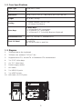
Sonata Elite
User’s Manual
Table of Contents
Introduction
1.1 Quiet Computing™ Features ……...……………......………….....… 1
1.2 Case Specifications ….…………………………....…......…….....… 2
1.3 Diagram ..……………………………………………..….…...........…. 2
Hardware Installation Guide
2.1 Setting Up ...........................................……….…......……..... 3
2.2 Power Supply Installation .......................……….…......…….. .. 3
2.3 Motherboard Installation ……………………………….......….....… 3
2.4 Internal 3.5” Device Installation ...........…………………..…....... 4
2.5 External 3.5” Device Installation .………………….…......…........ 4
2.6 External 5.25” Device Installation .......……………….…….....…. 5
2.7 Cable Organizer ..............................……………………….....…. 5
Connecting the Front I/O Ports
3.1 USB 2.0 Ports……………………………...……........……….....…… 5
3.2 eSATA Port………………………………...……......…..……….....… 6
3.3 AC’97 / HD Audio Ports......……………….................………...... 6
3.4 Power Switch / Reset Switch /
Hard Disk Drive LED Connectors ..………….…………..........…… 6
3.5 Rewiring Motherboard Header Connectors ...............………...... 7
Cooling System
4.1 TriCool™ Fan ........................................…….........……...…... 7
4.2 120mm Slot Blower ...........……….....……………..........…....... 8
4.3 Washable Air Filters .....................…….....……………….......... 8
At Antec, we continually refine and improve our products to ensure the highest quality. It’s
possible that your new case will differ slightly from the descriptions in this manual. This isn’t a
problem; it’s simply an improvement. As of the date of publication, all features, descriptions,
and illustrations in this manual are correct.
Disclaimer
This manual is intended only as a guide for Antec’s computer enclosures. For more
comprehensive instructions on installing the motherboard and peripherals, please
refer to the user’s manuals that come with those components.
Sonata Elite User’s Manual
The Sonata Elite comes without a power supply. Make sure you choose a power supply that
is compatible with your computer components and has a long enough power harness to
reach your motherboard and peripheral devices. We recommend our EarthWatts, TruePower,
or Signature Series power supplies for the latest ATX specification compliance, broad
compatibility, and power-saving capability.
Although care has been taken to prevent sharp edges in your Antec case, we strongly recommend
taking the appropriate time and care when working with it. Avoid hurried or careless motions.
Please use reasonable precaution.
This manual is not designed to cover CPU, RAM, or expansion card installation. Please
consult the motherboard manual for specific mounting instructions and troubleshooting.
Before proceeding, check the manual for your CPU cooler to find out if there are steps you
must take before installing the motherboard. While installing hardware, keep your case on a
flat, stable surface.
1.1 Quiet Computing™ Features
The Sonata Elite is designed with Quiet Computing™ in mind. Many unique design features
help make this case quiet and cool.
1.
Solid steel structure (0.8mm thick steel).
2.
Two layer (steel, polycarbonate) side and top panels to deaden noise.
3.
Multiple compartments dedicated for motherboard and hard disk drives.
4.
Unique hard drive mounting system for maximum noise reduction.
5.
Intake vents integrated with the dedicated HDD compartments to maximize cooling and
quiet computing.
6.
Quiet 120mm TriCool™ rear exhaust fan.
7.
Quiet 120mm exhaust blower with three-speed switch.
8.
Built-in cable management to tuck away extra cables behind the drive cage.
1
1.2 Case Specifications
Case Type
Quiet Mini Tower
Color
Black
Dimensions
18.9” x 8.1” x 17.3” / 48.1cm x 20.5 cm x 44 cm
Weight
21.6 lbs / 9.8 kg
Cooling
1 x Rear 120mm TriCool™ Fan
1 x 120mm Slot Blower
Drive Bays
7 Drive Bays:
- 3 x External 5.25” Drive Bays
- 4 x Internal 3.5” Drive Bays
- 1 x External 3.5” Drive Bay Bracket (Optional)
Motherboard Size
Mini-ITX, microATX, Standard ATX
2 x USB 2.0
1 x eSATA
AC’97/HD Audio In and Out
Front I/O Panel
1.3 Diagram
1.
120mm blower fan (optional)
2.
120mm rear exhaust TriCool™ fan
3.
Supports Mini-ITX, microATX or Standard ATX motherboard
4.
3 x 5.25” drive bays
5.
4 x 3.5” drive bays
6.
Power supply mount
7.
Air intake
8.
2 x USB 2.0 ports
9.
1 x eSATA ports
10. HD Audio / AC’97 ports
6
3
2
8
9
4
7
5
10
1
2
Hardware Installation Guide
2.1 Setting Up
1.
Place the case upright on a flat,
stable surface.
2.
Loosen the thumbscrews from the
left side panel. Remove by swinging
panel out.
3.
Loosen the thumbscrews from the
right side panel. Remove by swinging
panel out.
Note: Do not use your fingernail to
pry or lift the panels.
4.
Inside the case you should see some
wiring with marked connectors (USB, PWR etc.), an installed I/O panel, a plastic bag with
more hardware (screws, brass standoffs, specialty screws, etc.), a 5.25” to 3.5” adapter
for your external 3.5” device, six drive rails and the 120mm blower.
Note: Antec has made every effort to make the inside of your case as smooth as
possible. However it is still possible that there may be sharp edges, or other areas
where you can cut or scrape your hands or fingers. Please be careful as you assemble
your system or perform any upgrades.
2.2 Power Supply Installation
1.
With the case upright, place the power supply on
the support beam that runs from the 5.25” drive
bays to the back of the case.
Note: Typically you will have to pass the power
supply under the support beam to install or remove
the power supply. In an already built system this
will likely require removing your CPU heatsink.
2.
Push the power supply to the back of the case and
align the mounting holes.
3.
Attach the power supply to the case with the
included screws.
2.3 Motherboard Installation
This manual does not cover CPU, RAM, or expansion card installation. Please consult your
motherboard manual for specific mounting instructions and troubleshooting.
1.
Make sure you have the correct I/O panel for your motherboard. If the panel provided
with the case isn’t suitable, please contact
your motherboard manufacturer for the
correct I/O panel.
2.
To remove the I/O panel simply press the
panel from the outside pushing towards
the inside.
3.
Line up your motherboard with the standoff
holes, and remember which holes are lined
up. Not all motherboards will match with all
the provided holes; this is normal, and will
not affect functionality.
3
4.
Lift and remove motherboard.
5.
Screw the brass standoffs into the threaded holes that line up with your motherboard.
Do not over-tighten the standoffs. Some standoffs may be pre-installed for your convenience.
6.
Place your motherboard on the brass standoffs.
7.
Fasten your motherboard to the standoffs with the provided Phillips-head screws. Your
motherboard is now installed.
2.4 Internal 3.5” Device Installation
This case offers a unique hard disk mounting system. There
are two dedicated hard disk compartments right under the
external 5.25” drive cage. Each compartment can hold two
hard disk drives.
1.
Open the side panel as described in Setting Up. You
will find four metal mounting rails with soft silicone
grommets pre-installed inside each of the HDD
compartments. Each drive rail is fastened inside the
compartment with a thumb screw. You will need two
mounting rails to mount a HDD. One rail is fastened to
the upper wall of the compartment and the other rail is
fastened to the lower wall of the compartment.
2.
Remove both the upper and the lower mounting rails by
loosening the thumb screws.
3.
Fasten the rails to the sides of the HDD through the
silicone grommets with the special screws provided.
Note: Don’t over-tighten. Over-tightening
the screws will harm the vibration and noise
reduction qualities of the silicone grommets.
4.
Slide the HDD assembly into
the compartment.
5.
The connectors of the drive must face the
left side panel (away from the intake vent).
6.
Use the thumb screws to fasten the HDD
assembly into the case.
7.
Find the appropriate power connector on the
PSU and connect to the device.
8.
Find the appropriate data cable and connect
the hard drive to the motherboard.
2.5 External 3.5” Device Installation
To install a floppy or other external 3.5” device to the
5.25” to 3.5” adapter:
1.
Find the 5.25” to 3.5” adapter from the tool box.
2.
Place the device in the adapter and fasten with the
screws provided.
3.
Install the drive rails to the adapter as described in
the External 5.25” Device Installation section.
4.
Slide the drive into the drive bay until you hear
a click.
4
5.
Connect the appropriate connector(s) from the power supply to the hard drive(s) and
the motherboard.
2.6 External 5.25” Device Installation
There are three external 5.25” drive bays.
1.
Carefully remove the metal plate covering the drive bay.
2.
Make sure the clip on the end of the drive rail is angled away from the device and facing
forward. Mount a plastic drive rail on
each side of the 5.25”device.
3.
Slide the device into the drive bay until
you hear a click.
4.
Connect the appropriate data and
power cables from the device to the
motherboard.
2.7 Cable Organizer
Instead of running all the power cables into the motherboard compartment, the cables can be
organized between the motherboard and right side panel.
1.
Remove both side panels.
2.
Choose the cables you would like to hide or pass through the organizer behind the
motherboard tray.
3.
Run the cables to the organizer and use the cable ties to hold them in place.
Connecting the Front I/O Ports
3.1 USB 2.0 Ports
Connect the front I/O panel USB cable to the USB header pin on your motherboard. Check the
motherboard manual to ensure that it matches the table below:
Motherboard USB Pin Layout
1
2
9 10
Pin
Signal Names
Pin
Signal Names
1
USB Power 1
2
USB Power 2
3
Negative Signal 1
4
Negative Signal 2
5
Positive Signal 1
6
Positive Signal 2
7
Ground 1
8
Ground 2
9
Key (No Connection)
10
Empty Pin
5
3.2 eSATA Ports
You will find a SATA connector on a cable attached to the front ports. This internal SATA
connector is designed to connect to a SATA connector on your motherboard. This will allow
high-speed external hard disk enclosures such as the Antec MX-1 to run at the same speeds
as internally installed hard disks.
3.3 AC’97 / HD Audio Ports
There is an Intel® standard 10-pin AC’97 connector and an Intel® 10-pin HDA (High Definition
Audio) connector linked to the front panel of the case.
Pin
Signal Names
(HDA)
Pin
Signal Names
(AC’97)
1
MIC2 L
1
MIC In
2
AGND
2
GND
3
MIC2 R
3
MIC Power
4
AVCC
4
NC
5
FRO-R
5
Line Out (R)
6
MIC2_JD
6
Line Out (R)
7
F_IO_SEN
7
NC
8
Key (no pin)
8
Key (no pin)
9
FRO-L
9
Line Out (L)
10
LINE2_JD
10
Line Out (L)
10 6 4 2
97531
You can connect either the AC’97 or the HDA connector, depending on the model of the
motherboard. Locate the internal audio connectors from your motherboard or sound card and
connect the corresponding audio cable. Consult your motherboard or sound card manual for
the pin-out positions. Even if your system supports both audio standards, you may only use
one connector.
3.4 Power Switch / Reset Switch / Hard Disk Drive /
Power LED Connectors
Connected to your front panel are LED and switch leads for power, reset, HDD and Power
LED activity. Attach these to the corresponding connectors on your motherboard. Consult
your motherboard manual for
specific pin header locations.
For LEDs, colored wires are
positive ( + ). White or black
wires are negative ( – ). If the
LED does not light up when
the system is powered on,
try reversing the connection.
For more information on
connecting LEDs to your
motherboard, see your
motherboard manual.
Note: Polarity (positive and
negative) does not matter
for switches.
6
3.5 Rewiring Motherboard Header Connectors
If a case connector does not have the same pin-out as
the corresponding motherboard header, it may need to be
reconfigured. Examples could be for your USB header, audio
input header, or some other front panel connector such as
the Power Button connector.
Before performing any work, please refer to your motherboard
manual or your motherboard manufacturer’s website to be
sure of the pin-out needed for your connector. We strongly
recommend making a notated drawing before beginning work
so that you can recover if your work is disturbed.
1.
Determine which wires you need to remove in order
to rewire your plug to match the USB pin-outs on
your motherboard (refer to your motherboard manual).
Working on one connector at a time, use a very small
flathead screwdriver or similar tool to lift up on the black
tab located beside the gold posts (squares). This will
allow you to easily slide out the pins from the USB plug.
2.
Working carefully so as not to damage the wires,
connectors, or pins, slowly remove the pin from the
connector. Repeat these steps for each wire you need
to change.
3.
Slowly reinsert the pin into the correct slot of the connector, then snap closed the black
tab that was lifted in step 1. Repeat these steps for each wire you need to change.
Cooling System
4.1 TriCool™ Fan
There is one 120 x 25mm TriCool™ fan pre-installed at the rear of the case. This fan is
installed so the air will be blown out of the case. It has a three-speed switch that lets you
choose between quiet, performance, or maximum cooling. This switch is located at the rear
of the case. The default fan speed setting is Low.
Size:
120 x 25mm TriCool™ fan
Rated Voltage:
DC 12V
Operating Voltage:
10.2V - 13.8V
Speed
(RPM)
Input
Current
Airflow
Static Pressure
Noise
Input
Power
High
2000
0.24A
(max.)
2.24 m³ / min
(79 CFM)
2.54 mm-H2O
(0.10 inch-H2O)
30 dBA
2.9 W
Medium
1600
0.2A
1.59 m³ / min
(56 CFM)
1.53 mm-H2O
(0.06 inch-H2O)
28 dBA
2.4 W
Low
1200
0.13A
1.1 m³ / min
(39 CFM)
0.92 mm-H2O
(0.04 inch-H2O)
25 dBA
1.6 W
Note: The minimum voltage to start a 120mm TriCool™ fan is 5V. We recommend that
you set the fan speed switch to High if you choose to connect the fan(s) to a fan control
device or to the Fan-Only connector found on some Antec power supplies. A fan control
7
device regulates the fan speed by varying the voltage, which may start as low as 4.5V
to 5V. Connecting a TriCool™ fan set on Medium or Low to a fan-control device may
result in the fan not being able to start because the already lowered voltage from the
fan control device will be further reduced by the TriCool™ circuitry below 5V.
4.2 120mm Slot Blower
This case comes with a 120mm slot blower pre-installed inside
the case. The blower is installed so that the air is blown out to
the rear of the case. The blower has a three-speed switch that lets
you choose between Low (quiet) Medium (performance), and High
(maximum cooling).
Specifications
Size:
120 x 25 mm
Rated Voltage:
DC 12V
Operating Voltage:
10.8V ~ 13.2V
Speed
(RPM)
Input
Current
Airflow
Static Pressure
Acoustical
Noise
Input
Power
High
2500
0.22A
(max.)
0.33 m³ / min
(11.8 CFM)
6.89 mm-H2O
(0.27 inch- H2O)
39 dBA
2.6 W
Medium
2000
0.15A
0.26 m³ / min
(9.3 CFM)
4.30 mm- H2O
(0.17 inch- H2O)
34 dBA
1.8 W
Low
1500
0.12A
0.19 m³ / min
(6.8 CFM)
2.22 mm- H2O
(0.09 inch- H2O)
27 dBA
1.4 W
4.3 Washable Air Filters
From time to time it will be necessary to clean the installed filter. Not washing the air filter
will result in higher system temperatures and possible stability problems. We recommend
checking the air filter at least once a month initially. The frequency will change depending on
system usage (users whose systems run 24/7 will likely have to check/wash more often than
those who don’t use their systems every day) and on environmental conditions.
To clean the filters:
1.
Grip the center grill and pull away from the case to remove it from the intake vents.
2.
Wash the filter as needed.
3.
Latch the filter back into place.
8
Antec, Inc.
47900 Fremont Blvd.
Fremont, CA 94538
USA
tel: 510-770-1200
fax: 510-770-1288
Antec Europe B.V.
Stuttgartstraat 12
3047 AS Rotterdam
The Netherlands
tel: +31 (0) 10 462-2060
fax: +31 (0) 10 437-1752
Customer Support:
US & Canada
1-800-22ANTEC
[email protected]
Europe
+31 (0) 10 462-2060
[email protected]
www.antec.com
© Copyright 2008 Antec, Inc. All rights reserved.
All trademarks are the property of their respective owners.
Reproduction in whole or in part without written permission is prohibited.