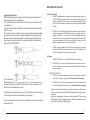
1
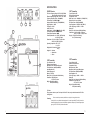
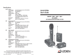
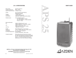
User’s Guide
500UDR • 51BT • 51HT • 51XT
ENHANCED PERFORMANCE
UHF WIRELESS RECEIVER and TRANSMITTERS
Azden Corporation, P.O. Box 10, 147 New Hyde Park Road, Franklin Square, NY 11010
vox - 516.328.7500 • fax - 516.328.7506 • email - [email protected]
© 2001 Azden Corporation
Printed in USA
P1011-04
SPECIFICATIONS
2
11
1
8
12
3
13
5
500UDR Receiver:
51BT Transmitter:
RF Carrier Frequency Range: 793.750 - 805.875 MHz
MicroComputer Controlled PLL Synth.
Effective Operating Range: 200 ~ 300 ft - 60 ~ 100m
± 3dB)
Frequency Response: 50Hz - 15kHz (±
μV
RF Sensitivity: (12dB SINAD)1.5μ
± 250kHz)
Adjacent Channel Selectivity: >70dB (±
Image Rejection: > 90dB
IF Rejection: > 90dB
Audio THD: <0.8%
Audio Output: -18dBm (600 Ω, ± 5kHz Dev., MIC)
XLR Output Impedance: 900 Ω Balanced
Phone Output Impedance: 30 Ω
Power Requirements: 6 x 1.5VDC (“AA” Batteries)
9 ~ 12VDC @ 170mA
Dimensions: 4.13 (H) x 4.13 (W) x 1.38 (D) inches
105 (H) x 105 (W) x 35 (D) mm
Operating Temperature: 32°° ~ 113°° F
0°° ~ 45°° C
Weight(w/6-“AA” batteries): 17.64 oz
500 g
Supplied: 2 – Antenna
1 - Screwdriver
1 - Velcro
Type of Emission: FM
Antenna: External Antenna
Pre-emphasis: 50 ms
MAX Input Level: -10dBm(Mic) +7dBm(MP-1H)
Microphone Unit: Lav or Headset
RF Output Power: 15mW (50mW MAX)
Input Impedance: 2.2K (Mic) 680K (MP-1H)
Audio Adj Range: -65dBm ~ -37dBm
Battery: 9V
Battery Life: 6 to 8 hours with Alkaline Battery
Dimensions: 100(H) x 64(W) x 27(D) mm
3.9 (H) x 2.5 (W) x 1.06 (D) inches
Weight: 127.5g (without battery)
4.5 oz (without battery)
51HT Transmitter:
51XT Transmitter:
Type of Emission: FM
Antenna: Internal Antenna
Microphone Unit: Unidirectional Dynamic
RF Output Power: 10m W (50mW MAX)
Input Impedance: 8K
Audio adj Range: m/2
Battery:2 1.5V (AA)
Battery Life: 6 to 8 Hours with Alkaline Battery
Dimensions: 56(D) 242(L) mm
2.2 (D) 9.5 (L) inches
Weight: 250g (without battery)
8.8 oz (without battery)
Type of Emission: FM
Antenna: Internal Antenna
Pre-emphasis: 50 ms
MAX Input Level: -7dBm
Microphone Unit: Dynamic Microphones
RF Output Power: 15mW (50mW MAX)
Input Impedance: 6K
Audio Adj Range: -63dBm ~ -18dBm
Battery: 9V
Battery Life: 6 to 8 hours with Alkaline Battery
Dimensions: 40 (ø) x 99(L) mm
1.57 (ø) x 3.9 (L) inches
Weight: 152g (without battery)
5.36 oz (without battery)
6
10A
7
10
4
4A
9
FCC Note:
These systems conform to part 74 and part 15 of the FCC rules, and you should contact the FCC office
for filing forms.
Licensing
i
Due to constant improvements specifiations are subject to change without notice.
Licensing of this, or any Azden wireless equipment is the user’s responsibility. The ability to receive a
license depends largely on the user’s classification, application and frequency. Contact the appropriate
agency (the FCC in the USA) for further information.
11
51BT with Lavaliere or Headset:
With someone talking into the microphone, turn the volume on the mixer or amplifier
to the desired level. If there is too much, or not enough gain, lower or raise the
volume on the receiver. If the sound is distorted, lower the input gain on the transmitter.
51BT with Instrument cable for electric guitars or basses (MP-1H):
Plug the cable into the guitar or bass. Set the instrument volume to the midway point.
While playing the instrument, turn the volume on the mixer or amplifier to the desired
level. If there is too much, or not enough gain, lower or raise the volume on the
receiver. If the sound is distorted, lower the input gain (6) on the transmitter.
51XT: With someone talking into the microphone, turn the volume on the mixer or
amplifier to the desired level. If there is too much, or not enough gain, lower or raise
the volume on the receiver. If the sound is distorted, lower the input gain on the
transmitter.
51HT:
With someone talking/singing into the microphone, turn the volume on the mixer/
amplifier to the desired level. If there is too much, or too little gain, adjust the volume
on the receiver. If the sound is distorted, move the microphone further away from the
sound source. Make sure that the LED is green when the mic/transmitter is turned
On. When the battery is low, the LED turns red indicating that the battery needs to be
changed.
INTRODUCTION
Thank you for selecting the Azden 500UDR as your portable/on-camera UHF receiver. We
are confident that it will perform beyond your expectations. For over 40 years Azden Corporation has been creating technologically advanced products. By taking advantage of the
latest in CAD design and SMT production techniques, Azden’s engineers are able to produce products that exceed the published specifications and perform well beyond the warranty period.
The 500UDR represents a breakthrough in on-camera, frequency-selectable UHF receivers. Its ‘Enhanced Performance’ assures you of the highest image rejection combined with
the finest in audio clarity. The crystal-controlled, PLL-synthesized mixer/local oscillator provides for extremely accurate frequency selection while the twin-antenna true diversity dual
front-end reduces multipath distortion caused dropouts to near zero.
In the real world of ENG the ability to be able to select a ‘clear’ frequency on the spot is vitally
important. Going out into the field with a single-frequency unit invites disaster since there is
no way of knowing what frequencies will be used by the other crews that are covering the
same story. Think of your 500UDR as your insurance policy - your assurance of getting the
story.
Designed by professionals - for professionals, the 500UDR will provide you with years of
worry-free, high-quality performance and will work flawlessly with the Azden 51BT, 51HT
and 51XT frequency-agile UHF transmitters.
NOTES:
- Remove the batties if the transmitter or receiver will not be used for an
extended period of time.
- Do not use or store the system in areas of high temperatures or humidity.
- Do not use this system near a broadcast station, airport, or airplanes, as it
may cause interference. If you are interfering with other transmissions you
must turn off the system.
- These systems contain no user serviceable parts. If unauthorized service is
performed it will void the warranty.
10
ii
TABLE OF CONTENTS
EXPLODED VIEW of 500UDR ................................................................................................ i
INTRODUCTION ...................................................................................................................... ii
RECEIVER SETUP .................................................................................................................. 1
Powering the receiver with batteries ........................................................................................... 1
Powering the receiver from the camera ...................................................................................... 1
Attaching the receiver to the camera with Velcro ......................................................................... 1
Attaching the Antennas ............................................................................................................... 1
Connecting the Output Cable ..................................................................................................... 1
INDICATORS AND CONTROLS ........................................................................................... 3-4
Multiple Frequency Example ..................................................................................................... 4
UHF FREQUENCY CHART ..................................................................................................... 4
500UDR TROUBLESHOOTING ............................................................................................... 5
51HT ......................................................................................................................................... 6
51BT ......................................................................................................................................... 7
51XT ...................................................................................................................................... 8-9
OPERATING THE SYSTEM ................................................................................................ 9-10
SPECIFICATIONS ................................................................................................................. 11
LICENSING ........................................................................................................................... 11
(6) LED INDICATORS
The POWER LED turns green when power is turned “On” or red if battery level is low. If this LED
lights up red replace the battery.
The AF PEAK LED lights up if the input level is set to high, indicating the onset of distortion. Lower
the input level so that the AF PEAK LED lights only occasionally.
To plug the 51XT onto a microphone (low impedance with XRL connector) first make certain the
locking-ring is turned fully up (rotate counterclockwise). Then plug the 51XT fully into the
microphones XLR connector and tighten by rotating the ring fully down (clockwise).
OPERATING THE SYSTEM:
Because this a frequency agile system, meaning that you choose the frequency of
both the transmitter and receiver via the group and channel controls, we cannot
stress enough that any transmitter/receiver pair that you want to transmit and receive
on MUST BE SET TO THE SAME FREQUENCY!
Additionally, multiple systems used in the same proximity must ALL BE ON THE
SAME GROUP SELECTION! To change the frequency that a transmitter/receiver
pair is already on YOU MUST TURN OFF BOTH TRANSMITTER AND RECEIVER
FIRST!
Do not place the receiver on a metal surface, and avoid obstructions between the
receiver and transmitter, since this could degrade the performance of the equipment.
First, make sure that the power to all your components is turned off. Connect an
audio cable from the output of the receiver (1/4 or XLR) to a mic/line input on your
audio mixer or amplifier. Plug the receiver’s AC adapter into the 12V input jack on
the receiver and then plug it into the AC electrical outlet. With the volume of your
mixer or amplifier set to minimum level, turn your system’s power on. Turn on the
transmitter(s). Make sure all LEDs on the receiver(s) and transmitter(s) are operating
as described in the preceding pages. Now set the receivers volume to the midway
point and adjust the volume level on your mixer or amplifier.
iii
9
RECEIVER SETUP
A. Powering the Receiver:
The 500UDR can be powered either by using internal batteries (#9) or from
the “DC IN” connector (#2).
To use internal batteries:
1. Remove the battery door (#10) by pressing in and down on the clip
(#10A) until the door is completely free of the unit.
2. Install 6 fresh/new Alkaline “AA” batteries following the polarity markings on the holder. DO NOT USE RECHARGEABLE BATTERIES!
3. Replace the battery door (#10).
New, fresh “AA” Alkaline batteries will last approximately 6 hours.
If the power-on LED starts to flash it is time to replace the batteries.
51XT plug-in XLR transmitter with 63 on-board user selectable UHF frequencies. Ideal for use with dynamic
microphones with XLR output.
(1) Open the battery compartment lid by sliding it down and raising it
(2) Insert one fresh alkaline 9-volt battery into the compartment. Make sure battery polarity is correct.
4
3
4
5
6
(3) Frequency select
The group knob allows you to select any of seven frequency groups (numbered from 0-6). The channel
knob allows you to select any of nine frequency channels (numbered from 0-8) within the selected group.
(4) Power and Audio switches
The power “On/Off” switch enables and disables all transmitter functions while the Audio “On/Off” switch turns
just the transmitter’s Audio signal on and off. Switching the Audio to “Off” will cause the receiver to mute using
the tone squelch circuitry in the receiver. This allows the microphone to be handled with no noise. The
“Phantom” switch allows the 51XT to provide 5V to power electret condenser microphones.
(5) Audio input LEVEL control
This enables you to adjust the input level of the microphone. Turn clockwise to increase, or counterclockwise to decrease the input level. A small screwdriver is supplied to make adjustments.
8
To use the camera’s DC Output
By using the dc input (#2) the 500UDR can accept between 9 and 12VDC @
1700mA directly from the camera or other power supply. The 4-pin connector uses pin 4 for positive (+) and pin 1 for negative (-). Pins 2 and 3 are not
used.
B. Mounting the Receiver:
To attach the 500UDR directly to the camera use the included Velcro.After
choosing an appropriate location on the camera, peel and attach the smooth
surface portion of the Velcro directly to the 500UDR (not the side with the
battery door), then attach the rough surface portion of the Velcro to the camera. For best reception try to mount the 500UDR in a location that keeps the
antennas above and away from the camera body. Be sure the surfaces on
the camera and 500UDR are clean and oil free before attaching the
Velcro.
C. Attaching the Antennas:
1. To attach the antenna, fit the BNC connector on the antenna on to the
receiver (#8), press down and rotate clockwise.
2. To remove antennas, rotate the antenna’s BNC connector counterclockwise and pull up.
D. Connecting the Output Cable:
1. It is necessary to connect the output (#1) of the 500UDR to the ‘MIC’ or
‘LINE’ input on the camera by means of a properly wired cable (not supplied). The connector on the 500UDR is wired with pin 1 as ground, pin 2
as plus (+) and pin 3 as negative (-).
1
3
4
5
6
1
2
The 51BT body-pack transmitter has 63 user selectable UHF frequencies and is ideal for lavaliere
and headset microphones. The optional MP-1H instrument cable allows the 51BT to work with
electric guitars and basses.
(1) Open the battery compartment lid by sliding it down and raising it.
(2) Insert one fresh alkaline 9-volt battery into the compartment. Make sure battery polarity is
correct.
(3) Frequency select:
The group knob (left) allows you to select any of seven frequency groups (numbered from 0-6).
The channel knob (right) allows you to select nine frequency channels (numbered 0-8) within the
selected group. Use the flat end of the provided tool to adjust these settings.
(4) Audio input Level Control:
Enables you to adjust the input level of the microphone or musical instrument. Turn clockwise to
increase, or counterclockwise to decrease the input level. Use the + end of the provided tool to
adjust this setting. The level control is factory-preset in the center position.
(5) Power and standby switches:
The power “On” and “Off” switch enables and disables all transmitter functions while the audio
switch “On” and “Standby” turn the audio off and on. Switching the transmitter to “Standby” will
cause the receiver to mute using the tone squelch circuitry in the receiver. This allows the
microphone to be handled with no noise.
(6) LED Indicator:
Turns green when the transmitter is turned on. This LED will also turn red to indicate that battery
2
level is low and the battery must be changed.
7
INDICATORS AND CONTROLS
Transmitter Descriptions:
51HT Handheld microphone transmitter with 63 on-board user selectable UHF
frequencies. Ideal for all vocal applications.
(1) To install batteries, turn the bottom half of the mic case counter-clockwise until it
is completely off.
(2) Insert two fresh alkaline “AA” batteries into the compartment. Make sure battery
polarity is correct.
(3) Frequency selection is achieved using the group and channel knobs which allows
you to select any of seven frequency groups (numbered from 0-6) and any of nine
frequency channels (numbered 0-8) within the selected group. After selecting the
desire frequency, replace bottom half of microphone case and turn clockwise until
snug. DO NOT OVER TIGHTEN.
A. LED Indicators (#3):
1. A/B ANT - depending upon which antenna is receiving the stronger signal, the A
or B ANT LED will glow green when both the transmitter and receiver are turned
ON and adjusted to the same frequency. Occasional rapid changing of the two
LEDs is a normal indication of the diversity front-end working to reduce multipath
distortion.
2.
AF PEAK - this indicator (#12) lights only when the receiver’s input level from the
transmitter exceeds unity. If the LED lights and there is no audible distortion no
adjustment is needed. If, on the other hand, the LED illuminates and there is
audible distortion, reduce the output from the microphone/transmitter by either
moving the microphone further from the sound source or in some other way reduce the output signal from the microphone/transmitter.
3.
POWER - with fresh batteries, this LED (#4A) lights red when the power switch
(#4)is turned ON. When the battery level drops to 4 volts this LED will flash on and
off. When this happens it is time to replace the batteries.
B. Controls:
1. POWER SWITCH (#4) - turns the 500UDR ON and OFF as indicated.
2.
(4) 2-Position switch
The bottom position is “Off” and the top position is “On”. Turning the transmitter Off
will cause the receiver to mute due to the tone squelch circuitry at the receiver. This
allows the mic to be handled with no noise.
(5) LED Indicator turns green when turned on. This LED will also turn red to indicate
that the battery level is low and the batteries must be changed.
(6) The antenna attaches to the bottom of the microphone. It is screwed on clockwise
and should be snug.
6
MONITOR (#5) - this level control adjusts the receiver’s earphone monitor volume. As indicated, turn clockwise to increase and counterclockwise to decrease
the earphone volume.
FREQUENCY SELECTION
3. GROUP (#6) - using the supplied screwdriver tool, rotate this switch to select one
of the seven (7) frequency groups (0-6). Note: positions 7-9 do not apply.
4.
CHANNEL (#7) - using the supplied screwdriver tool, rotate this switch to select
one of the NINE (9) frequency channels (0-8). Note: position 9 does not apply.
This method of group/channel selection provides 63 possible choices. ANY transmitter that is to be used with this 500UDR MUST be adjusted to the same group/channel
combination.
When using multiple systems, all receivers and transmitters MUST use the same
GROUP number to avoid intermodulation distortion. Additionally, all receivers and transmitters MUST use different CHANNEL numbers.
3
500UDR TROUBLESHOOTING
The single most important thing to ALWAYS check when trouble arrises are the batteries.
Make sure they are fresh and the POWER LED is glowing brightly.
Example: Operating 3 systems at the same time
Receiver
Transmitter
System #1
Group Channel
2
4
2
4
System #2
Group Channel
2
5
2
5
System #3
Group Channel
2
6
2
6
NOTE: To change the group/channel combination frequency of a receiver
and transmitter that are already ON, BOTH THE TRANSMITTER AND RECEIVER MUST BE TURNED OFF.
SYMPTOM
No POWER LED
CAUSE
a. Receiver switch is set to “OFF”
b. External 12VDC power source is not connected or is malfunctioning
c. Dead or very weak batteries
No ANT LED
a. Transmitter battery dead
b. Transmitter not turned “ON”
c. Transmitter and receiver not both adjusted to the same
GROUP and CHANNEL
d. Receiver’s antenna’s are not installed
UHF FREQUENCY CHART
CHANNEL
4
GRP
0
1
2
3
4
5
6
7
8
0
794.500
795.750
797.750
798.000
799.500
800.500
802.375
804.750
805.875
1
794.375
795.625
797.625
797.875
799.375
800.375
802.250
804.625
805.750
2
793.750
795.000
797.000
797.250
798.750
799.750
801.625
804.000
805.125
3
794.250
795.500
797.500
797.750
799.250
800.250
802.125
804.500
805.625
4
794.125
795.375
797.375
797.625
799.250
800.125
802.000
804.375
805.500
5
794.000
795.250
797.250
797.500
799.000
800.000
801.975
804.250
805.375
6
793.875
795.125
797.125
797.375
798.875
799.875
801.750
804.125
805.250
5.
OUTPUT (#8) - switch to the appropriate position depending on whether the 500UDR
is plugged into the ‘LINE’ or ‘MIC’ input on the camera.
6.
PHONE JACK (#11) - nominal 30 Ω headphone/earphone jack. Use either 3.5mm
mono or stereo (mono to both ears) connector. Earphones with an impedance
between 30 Ω and 300 Ω should provide adequate volume while headphones
with an 8 Ω impedance will most likely provide volume that is too low.
ANT LED is lit but NO audio a. Check that microphone is attached to transmitter, turned ON
and operating properly
b. OUTPUT switch is in the wrong position
c. OUTPUT connector cable is not installed or is defective
AF PEAK LED is always lit
a. 500UDR is receiving a signal that is too strong. Move the
transmitter further away or reduce the transmitter’s output
5