1
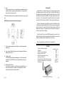
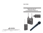
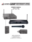
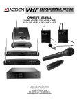
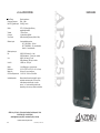
20 watts continuous
65Hz – 18kHz
101dB @ 1 m eter
W oofer
5.25" (133.35m m ) high efficiency
m agnetically shielded
1" (25m m ) dom e
1 st order passive @ 8kHz
-6dB/octave sliding lowpass (3kH z to 8kHz)
Tweeter
Crossover
Tone Control
W ireless inputs
2 user-installable receivers
VHF (169-213M Hz) – 30 fixed
UHF (794-806M Hz) – 63 user-selectable
Infrared – 2 user-selectable
W ired inputs/output
M ic
Line-O ut
-81dBV (0.089m V R M S ) for 1 watt
100K Ω unbalanced, ¼ " phone jack, variable
-40dBV (10m V R M S ) for 1 watt
10K Ω unbalanced, RC A jack, variable
+15dBV m ax - R CA jack
W eight
Dim ensions
Battery Life
AC Power Requirem ents
11lb (4.99kg) approx. w/out receivers
12.4"H x 7.09"W x 5.6"D (315 x 180 x 142m m )
6-8 hours / 8 hours to recharge
110-125 VAC - 60H z for Power Pack
Included w/speaker
Rem ovable wall-m ount bracket with 2 screws
and rubber anti-rotate pads, AC Power Pack,
4 self-adhesive anti-skid pads, 4 m odule
screws, 1 or 2 noise-canceling circuit boards
(depending on how m any m odules are installed)
Line
AZDEN Corp., P.O. Box 10, 147 New Hyde Park Road, Franklin Square, NY 11010
516.328.7500 [vox] • 516.328.7506 [fax]
[email protected] [email] • www.azdencorp.com [on the web]
- Specifications subject to change without notice 25b-1001
© 2006 Azden Corp. • Printed in USA
APS 25b
Rated Power
Frequency Response
M ax SPL @ rated output
MULTI-PURPOSE / MULTI-FUNCTION BATTERY POWERED SPEAKER SYSTEM
APS 25b SPECIFICATIONS
USER’S GUIDE
(5) 3-Position Switch
left position:OFF - Middle position:STANDBY - Right position:ON
In the “STANDBY” position, the audio is muted.
(6) LED Indicator
Red when the switch is in “STANDBY” position - Green in “ON” position.
(7) Audio Output Connector
This 3.5mm mono connector is where the mic is plugged in. This connector was designed to be used with a special “screw-down” connecting jack
that eliminates the possibility of the jack being accidentally pulled out. A
standard 3.5mm mono jack can also be used but will not afford the extra
protection.
(the lighting flash with arrowhead symbol within an
equilateral triangle) is intended to alert the user to the
presence of uninsulated "dangerous voltage" within
the product's enclosure that may be of sufficient
magnitude to constitute a risk of electric shock to
persons: and
(the explanation point within an
equilateral triangle) is intended to alert the user to the
presence of important operating and maintenance
(servicing) instructions in the literature accompanying
the product.
(8) Metal Belt Clip
Used to attach the 32BT securely to a belt.
NOTE: Remove the battery if the transmitter is not used for a long period of time.
Installing an APS-H Carry Handle:
AAPS 25b using wall-mount bracket
There is an optional handle for the APS 25b that is easy to attach to the top
of the speaker. The handle screws into the threaded hole on the top of the speaker
by turning it clockwise. Tighten the handle until it is "square" with the speaker but
do not overtighten. Instead, once the desired position is achieved, stop turning
the handle and tighten the nut clockwise at the bottom of the handle using a
wrench or pliers.
page 13
(7) Level:
Turn clockwise to increase, or counterclockwise to decrease the input level.
A small screwdriver is supplied to make adjustments. The level control is
factory-preset in the center position.
NOTE: Remove the battery if the transmitter will not be used for a long period of
time.
32BT Body-pack transmitter with lavalier microphone:
Introduction
Congratulations. You have chosen one of the most versatile powered
loudspeaker systems on the market today. The Azden® APS 25b is a
sophisticated 4-channel mixable speaker system that allows you to utilize
two different wireless inputs in addition to a wired microphone and a linelevel input - all at the same time if needed. The master, front mounted,
volume knob controls the overall level of all four inputs simultaneously.
Housed in a high-impact polycarbonate cabinet, the APS 25b can be
wall mounted using the included bracket, stand-mounted or simply placed
wherever needed. The Auto On/Off circuitry makes using the APS 25b
simple and convenient. The internal battery will operate the speaker for
6-8 hours and is easily recharged.
To get the most from your new APS 25b Speaker System be sure to
carefully read this user’s guide, paying particular attention to the receiver
module(s) installed and the transmitter(s) you’ve chosen.
Again, congratulations, and thanks for choosing Azden®.
(1) Open the battery compartment lid by sliding it in the direction indicated
and raising it.
(2) Insert one fresh Alkaline 9-volt battery into the compartment. Make sure
battery polarity is correct.
(3) Frequency Label
The Frequency label indicates what frequency (in MHz) the transmitter
broadcasts on. The AZDEN receiver in use must also be on the same
frequency.
Contents
Cautions and Safety Information
Introduction
APS 25b rear panel diagrams
Installing an APS module
APS 25b inputs/output and controls
Mounting the APS 25b
Using APS UR module and UHF transmitters
Using APS VR module and VHF transmitters
Specifications
inside front cover
page 1
page 2
page 3
page 3-4
page 4
page 5-8
page 9-13
back cover
(4) Audio Input Level Control
Turn clockwise to increase, or counterclockwise to decrease the input
level. A small screwdriver is supplied to make adjustments. The level
control is factory-preset in the center position.
page 12
AAPS VR VHF receiver module
page 1
31XT Plug-in transmitter adaptor:
Note:The 31XT is designed to turn any wired dynamic metal-body microphone
that has an XLR output into a wireless microphone.
1
Connecting the 31XT:
Disconnect the microphone cable from the microphone by pushing down on the
release button where the microphone and cable connect. Connect the 31XT by
lining up the pins on the microphone with the holes on the transmitter, and insert.
Push the 31XT into the microphone until it locks into place.
Removing the 31XT:
Push down on the release button and pull out.
3
2
5
6
7
4
8
9
12
(1) Turn the bottom half of the case counterclockwise until it is completely off.
(2) Insert one fresh alkaline “AA” battery into the compartment. Make sure
battery polarity is correct. Replace the bottom half of the case and turn
clockwise until snug. DO NOT OVERTIGHTEN.
(3) Frequency Label:
The frequency label indicates what frequency (in MHz) the transmitter broadcasts on. The AZDEN receiver in use must also be on the same frequency.
(4) Power Off/On:Switches the transmitter off or on.
A
B
13
11 10
C
(5) Audio Off/On:
Slide the switch to “On” for normal operation. Slide it to “Off” to mute the
audio.
NOTE: When turning the transmitter on, slide the Power “On” first, and then slide
the Audio to “On”. When turning the transmitter off, first slide the Audio to “Off”.
(6) LED:
RED when Power is “On” and Audio is “Off”. GREEN when Power and Audio
are both “On”.
page 2
page 11
(6) 3-Position Switch
Left position:OFF - Middle position:STANDBY - Right position:ON
In the “STANDBY” position, the audio is muted.
(7) LED Indicator
RED when switch is in “STANDBY” position - GREEN in “ON” position.
NOTE: Remove the battery if the transmitter will not be used for a long period of
time.
31HT Handheld Microphone Transmitter:
(1) Turn the bottom half of the microphone case counterclockwise until it is
completely off.
(2) Insert one fresh Alkaline “AA” battery into the compartment. Make sure battery polarity is correct. Then replace bottom half of microphone case and
turn clockwise until snug. DO NOT OVERTIGHTEN.
(3) The frequency label indicates what frequency (in MHz) the transmitter broadcasts on. The AZDEN receiver in use must be on the same frequency.
(4) 3-Position Switch
Bottom position:OFF - Middle position:STANDBY - Top position:ON
In the “STANDBY” position, the audio is muted.
(5) LED indicator
RED when the switch is in “STANDBY” position - GREEN in “ON” position.
NOTE: Remove the battery if the transmitter is not used for a long period of time.
page 10
Installing an APS module... (see photo - page 1)
All APS modules install into the APS 25b in the same manner. To
install, first remove the blank panel by loosening the two retaining thumb
screws. Next remove the “shorting board” by pulling it straight out. Now,
simply slide the module into the slot and lightly press until the connector
in the rear engages and the front panel is flush. Last, replace the two
thumb screws and tighten snugly. Any APS module can be inserted into
either slot. Save the “shorting board(s)” for possible later use.
NOTE: If you purchased your APS 25b with one or two modules, they
have already been installed.
The APS 25b Inputs/Outputs and Controls...
A. MASTER VOLUME CONTROL - controls the overall volume of the
APS 25b as well as the LINE OUT (8) connector.
B. TONE - this is a variable frequency high-cut tone control that is primarily used to reduce high-frequency feedback. The control is
essentially flat when turned fully clockwise and reduces more high
frequencies as it is rotated counterclockwise.
C. POWER LED - displays power state of speaker. See (4) for details.
1. CHAN A slot - any module can be installed here.
2. CHAN B slot - any module can be installed here.
3. MIC INPUT - plug a wired dynamic microphone in here. This 1/4 inch
jack is designed to accept a low impedance microphone. The input
volume is controlled by the MICROPHONE LEVEL knob (5).
4. OFF/AUTO/ON switch - this controls the power for the speaker after
the MASTER POWER SWITCH (12) is placed in the ON position.
• The speaker is essentially OFF with this switch in the OFF position.
The front panel LED (C) will glow Red.
• The speaker will come ON from its standby mode automatically when
any signal is sensed when the switch is in the AUTO position. The
POWER LED (C) will turn from Red to Green. 10 minutes after all
audio stops the speaker will return to its standby mode and the
POWER LED (C) will return to Red.
• The speaker is ON at all times when the switch is in the ON position.
The POWER LED (C) will glow Green.
5. MIC LEVEL - this knob controls the input volume of the microphone
plugged into the MIC INPUT (3). It is always good practice to leave
the control turned all the way down (full counterclockwise) when no
microphone is being used.
6. LINE LEVEL - this knob controls the input volume of anything plugged
into the LINE IN (7) jack.
page 3
7.
8.
9.
10.
11.
13.
LINE IN - this mono RCA jack is designed to accept audio from
devices such as CD players, video tape players or anything else with
a line-level audio output. The input volume is controlled by the LINE
LEVEL knob (6).
LINE OUT - this mono RCA jack provides line-level audio to drive
additional speakers or other audio devices with a line-level input.
The level is controlled by the MASTER VOLUME CONTROL (A) on
the front panel. If this output is used to drive the LINE IN (7) of a
second APS 25b, the MASTER VOLUME CONTROL (A) will control the overall volume of both speakers.
DC JACK - this is where the removable DC plug is attached to the
speaker. With the Charge Pack plugged into the speaker and a
110VAC wall plug, the speaker can be recharged. The speaker can
be used while charging. Be sure to use ONLY the Charge Pack that
is supplied with the speaker.
CHARGE LED - Indicates that the speaker is charging.
LOW LED - Indicates that the battery is low and needs recharging.
FULL LED - Indicates that the battery has been fully charged.
Mounting the APS 25b
• Wall Mounting (see photo - inside cover)
The APS 25b is supplied with a wall mounting bracket. It can be attached to the speaker via the built-in 1/4" X 20 threaded holes on the top
and bottom of the speaker using the included large screws. Supplied rubber pads can be applied to the inside surface of the bracket to protect the
speaker surface from scratching and reduce the possibility of the speaker
rotating in the bracket. The bracket can be attached to the desired surface using a number of different fasteners. Be sure to use fasteners that
are appropriate for the surface you are mounting to and that can support
the speaker’s weight. Once the desired position is achieved, tighten the
screws securely.
• Stand Mounting
The APS 25b has two industry-standard 5/8" x 27 threaded inserts
moulded into the cabinet - one on the bottom and one on the side. These
allow the speaker to be securely mounted to a stand (such as a microphone stand). Be sure to tighten the speaker securely to the stand. Also,
be sure that the stand can support the weight of the speaker and that it
will be stable with that weight attached.
• Flat surface
Four self-adhesive anti-skid pads can be applied to the bottom or side
of the speaker to help stop it from moving when placed on a flat surface.
page 4
Using an APS VR module and VHF Transmitter(s)...
The APS VR receiver module comes pre-adjusted to one of 30 different VHF frequencies between 169MHz and 213MHz. The particular
frequency(s) you have were chosen to not interact/interfere with TV stations in your area. After installing the module (page 2) you will have to
attach the antenna and position it as close to vertical as possible. The
volume control on the module adjusts the input volume of that particular
module. Try to keep it set near its mid point for best performance.
Transmitters...
Model 31LT: Lavalier microphone with body-pack transmitter. Ideal for speaking
applications such as Lecturers, Actors, Actresses, etc.
(1) Open the battery compartment lid by sliding it down and raising it.
(2) Insert one fresh Alkaline 9-volt battery into the compartment. Make sure the
battery polarity is correct.
(3) Frequency Label
The Frequency label indicates what frequency (in MHz) the transmitter broad
casts on. The AZDEN receiver in use must also be on the same frequency.
(4) 31LT lavalier mic:
Clips onto a tie, lapel, etc. The transmitter’s cable doubles as an antenna.
Extend the cable as much as possible for the best performance.
(5) Audio Input Level Control
Turn clockwise to increase, or counter-clockwise to decrease the input level.
A small screwdriver is supplied to make adjustments. The level control is
factory-preset in the center position.
page 9
(4) Power and Audio switches
The power “On/Off” switch enables
and disables all transmitter functions
while the Audio “On/Off” switch turns
just the transmitter’s Audio signal on
and off. Switching the Audio to “Off”
will cause the receiver to mute using
the tone squelch circuitry in the
receiver. This allows the microphone
to be handled with no noise. The “Phantom” switch allows the 51XT to
provide 5V to power electret condenser microphones.
(5) Audio input LEVEL control
This enables you to adjust the input level of the microphone. Turn
clockwise to increase, or counterclockwise to decrease the input level.
A small screwdriver is supplied to make adjustments.
4
3
6
5
4
(6) LED INDICATORS
The POWER LED turns green when power is turned “On” or red if
battery level is low. If this LED lights up red replace the battery.
The AF PEAK LED lights up if the input level is set to high, indicating
the onset of distortion. Lower the input level so that the AF PEAK LED
lights only occasionally.
Using an APS UR module and UHF Transmitter(s)...
The APS UR receiver module features 63 user-selectable frequecies
within the 793-806MHz range. After installing the module (page 2) you
will have to attach the antenna and position it as close to vertical as possible. You will then select the frequency you wish to use following the
procedure below. The volume control on the module adjusts the input
volume of that particular module. Try to keep it set near its mid point for
best performance.
Frequency Selection
The group knob (GR) allows you to select any of seven frequency
groups (numbered from 0-6). The channel knob (CH) allows you to
select any of nine frequency channels (numbered 0-8) within the
selected group. Any receiver/transmitter pair must be on the same
group and frequency to operate properly. Be sure that both the transmitter and the receiver are OFF before selecting/changing the frequency.
When using more than one system, all receivers and transmitters
must be set to the same group to avoid intermodulation distortion
while all transmitter/receiver pair must be on different frequencies.
System #1
System #2
System #3
System #4
Group Channel
Group Channel
Group Channel
Group Channel
Receivers
2
4
2
5
2
6
2
7
Transmitters
2
4
2
5
2
6
2
7
To change the frequency that a transmitter/receiver pair is already set
on YOU MUST FIRST TURN OFF BOTH THE TRANSMITTER AND
RECEIVER (SPEAKER)!
UHF Transmitters ...
The 51HT is a handheld microphone transmitter with 63 on-board user
selectable UHF frequencies. Ideal for all vocal applications.
To plug the 51XT onto a microphone (low impedance with XRL connector) first make certain the locking-ring is turned fully up (rotate counterclockwise). Then plug the 51XT fully into the microphones XLR connector and tighten by rotating the ring fully down (clockwise).
page 8
(1) To install batteries, turn the bottom half of the mic case counterclockwise until it is completely off. Insert two fresh alkaline “AA”
batteries (2) into the compartment. Make sure battery polarity is correct.
(3) Frequency select
The group knob allows you to select any of seven frequency groups
page 5
(numbered from 0-6). The channel knob allows you to select any of
nine frequency channels (numbered 0-8) within the selected group.
3
4
Replace bottom half of microphone case and turn clockwise until snug.
DO NOT OVER TIGHTEN.
5
6
1
(4) 2-Position switch
The bottom position is “Off” and the top position is “On”. Turning the
transmitter Off will cause the receiver to mute due to the tone squelch
circuitry at the receiver. This allows the mic to be handled with no noise.
(5) LED Indicator turns green when turned on. This LED will also turn
red to indicate that the battery level is low and the batteries must be
changed.
(6) The antenna attaches to the bottom of the microphone. It is screwed
on clockwise and should be snug.
The 51BT body-pack transmitter has 63 user selectable UHF frequencies and is ideal for lavaliere and headset microphones. The optional
MP-1H instrument cable allows the 51BT to work with electric guitars
and basses.
(1) Open the battery compartment lid by sliding it down and raising it.
Then, insert one fresh alkaline 9-volt battery (2) into the compartment.
Make sure battery polarity is correct.Make sure battery polarity is
correct.
(3) Frequency select
The group knob allows you to select any of seven frequency groups
(numbered from 0-6). The channel knob allows you to select any of
nine frequency channels (numbered from 0-8) within the selected
group.
page 6
6
2
(3) Frequency select:
The group knob (left) allows you to select any of seven frequency
groups (numbered from 0-6). The channel knob (right) allows you to
select nine frequency channels (numbered 0-8) within the selected
group. Use the flat end of the provided tool to adjust these settings.
(4) Audio input Level Control:
Enables you to adjust the input level of the microphone or musical
instrument. Turn clockwise to increase, or counterclockwise to decrease the input level. Use the + end of the provided tool to adjust this
setting. The level control is factory-preset in the center position.
(5) Power and standby switches:
The power “On” and “Off” switch enables and disables all transmitter
functions while the audio switch “On” and “Standby” turn the audio off
and on. Switching the transmitter to “Standby” will cause the receiver to
mute using the tone squelch circuitry in the receiver. This allows the
microphone to be handled with no noise.
(6) LED Indicator:
Turns green when the transmitter is turned on. This LED will also turn
red to indicate that battery level is low and the battery must be
changed.
The 51XT plug-in XLR transmitter with 63 on-board user selectable
UHF frequencies is ideal for use with dynamic microphones with XLR
output.
(1) Open the battery compartment lid by sliding it down and raising it.
Then insert one fresh alkaline 9-volt battery (2) into the compartment.
page 7