1
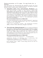
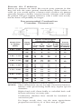
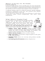
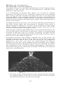
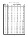
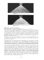
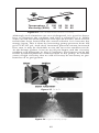
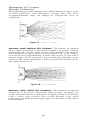
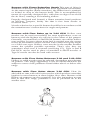
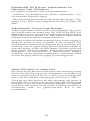
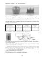
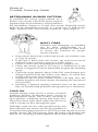
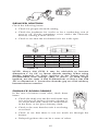
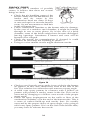
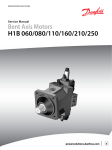
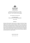
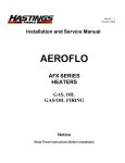
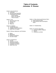
A TOTAL LOOK AT
OIL BURNER NOZZLES
ISO 9001 CERTIFIED
A Reference Guide for the
Burner Service Technician
The complete oil heating system begins at the tank and
ends at the chimney. At the heart of the system is a tiny,
yet important piece of hardware — the nozzle. It
performs the vital functions that keep the flame
generating warm, comfortable heat. In fact, it plays
such a significant role in the entire system that we feel
the technician should know all about the nozzle.
In this reference guide, we’ll explore how the nozzle
works with other components of the system and give
you some oil nozzle facts that can help you maintain a
clean, reliable and economical heating system.
Contents
Page
Why Use Nozzles? . . . . . . . . . . . . . . . . . . . . . . . . . . . . . . . . 1
What the Nozzle Does . . . . . . . . . . . . . . . . . . . . . . . . . . . . . 2
How A Nozzle Works . . . . . . . . . . . . . . . . . . . . . . . . . . . . . . 3
Nozzle Selection; Delavan Nozzles. . . . . . . . . . . . . . . . . . . 4
Nozzle Types . . . . . . . . . . . . . . . . . . . . . . . . . . . . . . . . . . . . . 4
Burner Manufacturers’ Nozzle Recommendations;
Nozzle Interchange . . . . . . . . . . . . . . . . . . . . . . . . . . . . . 6
Flow Rate; Proper Flow Rates . . . . . . . . . . . . . . . . . . . . . . . 7
Determination of Proper Firing Rate for a House . . . . . . . 8
Spray Angle; Spray Pattern . . . . . . . . . . . . . . . . . . . . . . . . . 9
Burner Air Patterns; Recommended Combustion
Chamber Dimensions . . . . . . . . . . . . . . . . . . . . . . . . . . 10
Effects of Excess Air on Nozzle Performance;
What Affects Droplet Size? . . . . . . . . . . . . . . . . . . . . . 11
Effects of Pressure on Nozzle Performance . . . . . . . . . . 12
Effects of Pressure on Nozzle Flow Rate . . . . . . . . . . . . . 13
Effects of Viscosity on Nozzle Performance . . . . . . . . . . 14
Examples of Proper Nozzle Selection. . . . . . . . . . . . . . . . 15
Fuel Saving Devices for the Consumer . . . . . . . . . . . . . . 18
Preheaters and Chemical Additives . . . . . . . . . . . . . . . . . 18
Residential Oil Burner Adjustments for
Optimum Fuel Utilization . . . . . . . . . . . . . . . . . . . . . . . 19
Good Filtration Is Important. . . . . . . . . . . . . . . . . . . . . . . . 19
Clean Air Technology; ProTek™ Nozzle System . . . . . . . 20
Delavan Filtration Products; Nozzle Filters
and Strainers; Line Filter . . . . . . . . . . . . . . . . . . . . . . . 21
Other Accessories . . . . . . . . . . . . . . . . . . . . . . . . . . . . . . . 22
Nozzle Care and Service Tips . . . . . . . . . . . . . . . . . . . . . . 23
General Trouble Shooting Guide . . . . . . . . . . . . . . . . . . . 26
Questions Asked by Oil Heating Service Technicians . . 30
Other Delavan Nozzles Available . . . . . . . . . . . . . . . . . . . 33
NOTE
The information in this pamphlet is based on
experience and is to be used as a general guide only.
WARNING
Improper modification to combustion units may create
a fire hazard resulting in possible injury. Contact the
original equipment manufacturer before modifying the
combustion unit.
Why Use Nozzles?
For a better understanding of how a nozzle fits into the
performance of an oil burner, let us first review the steps in the
process of efficient combustion.
Like all combustible matter, the oil must first be vaporized—
converted to a vapor or gas—before combustion can take
place. This is usually accomplished by the application of
heat.
The oil vapor must be mixed with air in order to have oxygen
present for combustion.
The temperature of this mixture must be increased above the
ignition point.
A continuous supply of air and fuel must be provided for
continuous combustion.
The products of combustion must be removed from the
combustion chamber.
The simplest way to burn fuel oil is the old vaporizing pot type
burner in which heat is applied to a puddle of oil, thus vaporizing
the fuel. These vapors are then burned after mixing with the
proper amount of air.
In most applications, this method of vaporizing is too slow for
high rates of combustion and cannot be controlled in the low rates,
which leads back to the original question of why nozzles are used.
One of the functions of a nozzle is to atomize the fuel, or break it
up into tiny droplets which can be vaporized in a much shorter
period of time when exposed to high temperatures. This booklet
will be concerned primarily with the high-pressure atomizing
nozzle since it is the most common in the Oil Heat Industry.
1
What the Nozzle Does
The atomizing nozzle performs three
vital functions for an oil burner:
1. Atomizing As just discussed, it
speeds up the vaporization process
by breaking up the oil into tiny
droplets…something like 55-billion
per gallon of oil at a pressure of 100psi (standard in the industry). The
exposed surface of a gallon of oil is
thereby expanded to approximately 690,000 square inches of
burning surface. Individual droplet sizes range from .0002
inch to .010 inch. The smaller droplets are necessary for fast
quiet ignition and to establish a flame front close to the
burner head. The larger droplets take longer to burn and
help fill the combustion chamber.
2. Metering A nozzle is so designed and dimensioned that it
will deliver a fixed amount of atomized fuel to the
combustion chamber…within approximately plus or minus
5% of rated capacity. This means that functional dimensions
must be controlled very closely. It also means that nozzles
must be available in many flow rates to satisfy a wide range
of industry needs. Under 5.00 GPH, for example, over 20
different flow rates and 6 different spray angles are
considered standard.
3. Patterning A nozzle is also expected to deliver the
atomized fuel to the combustion chamber in a uniform spray
pattern and spray angle best suited to the requirements of a
specific burner. More details on patterns and angles later.
2
How A Nozzle Works
Now that we know what a nozzle is supposed to do, let’s see how
it does it.
But before we do, let’s take a look at the cutaway showing the
functional parts of a typical Delavan nozzle (Fig. 1). The flow rate,
spray angle and pattern are directly related to the design of the
tangential slots, swirl chamber and orifice.
FIGURE 1 Cutaway view of a Delavan nozzle.
First, a source of energy is needed to break up the oil into small
droplets. Therefore pressure is supplied to the nozzle, usually
from a motor-driven pump at 100-150 psi (Fig. 2). But pressure
energy alone doesn’t do the job. It must first be converted to
velocity energy and this is accomplished by directing the
pressurized fuel through a set of slots which are cut in the
distributor at an angle, or tangentially, to create a high velocity
rotation within the swirl chamber. At this point, about half of the
pressure energy is converted to velocity energy.
As the oil swirls, centrifugal force is exerted against the sides of the
chamber, driving the oil against the orifice walls, leaving a void or
core of air in the center. The oil then moves forward out of the orifice
in the form of a hollow tube. The “tube” becomes a cone shaped
film of oil as it emerges from the orifice, ultimately stretching to a
point where it ruptures and throws off droplets of liquid.
How a Nozzle Works
FIGURE 2 How a nozzle works.
3
Nozzle Selection
To match a nozzle to a burner takes field-service experience, trialand-error, or a good foundation of understanding angles, rates
and patterns.
Nozzle Ratings and Testing
To insure consistent quality, every Delavan
nozzle is tested for flow rate and spray angle on
modern, high instrumented test stands. Spray
quality is observed during testing for
uniformity, balance and flutter.
Delavan Nozzles
Nozzle
Vial
Test oil is mixed to nominal no. 2 oil
Type
Color
specifications. The viscosity is
A
Red
maintained within:1±.04 centistokes
Black
(.03 SSU), gravity to a total spread of Del-O-Flo A
B
Royal Blue
11/2° APl and temperature at 80°F Del-O-Flo B
Gold
±2° F. Test pressure is set at 100 psi.
W
Green
These conditions are continuously
monitored and instrument accuracy is maintained within ±.5% or
better. Nozzle testing is conducted in an air-conditioned, controlled
environment, with a temperature variation of 4° F maximum.
Nozzle Types
Type A
Hollow Cone
(Creates stable flame
at low flows)
Figure 3
Hollow Cone Nozzle (Type A)
Hollow cone nozzles can be used in burners with a hollow air
pattern and also for use in small burners (those firing 1.00 GPH
and under), regardless of air pattern. Hollow cone nozzles
generally have more stable spray angles and patterns under
adverse conditions than solid cone nozzles of the same flow rate.
This is an important advantage in fractional gallonage nozzles
where high viscosity fuel may cause a reduction in spray angle
and an increase in droplet size.
Type A nozzles produce a spray which delivers fine droplets
outside the periphery of the main spray cone. These fine droplets
greatly enhance ignition and create a stable flame for use with
flame retention burners.
For Type A Del-O-Flo® low flow nozzles (see page 5).
4
Type B
Solid Cone
(For larger burners & where
air pattern is heavy in the
center or for long fires)
Figure 4
Solid Cone Nozzle (Type B)
Type B nozzles produce a spray which distributes
droplets fairly uniformly throughout the complete pattern.
This spray pattern becomes progressively more hollow at high
flow rates, particularly above 8.00 GPH. These nozzles may be
used in larger burners (those firing above 2.00 or 3.00 GPH) to
provide smoother ignition. They can also be used where the air
pattern of the burner is heavy in the center or where long fires are
required.
For Type B Del-O-Flo low flow nozzles see below.
Type W
(Can be used in place of
A or B types in reducing
specific problems)
Figure 5
Type W Nozzle
Type W nozzles produce a spray which is neither
truly hollow nor solid. These nozzles frequently can be
used in place of either solid or hollow cone nozzles between .40
GPH and 8.00 GPH, regardless of the burner’s air pattern. The
lower flow rates tend to be hollower. Higher flow rates tend to be
more solid.
Del-O-Flo® Nozzle
U.S. Patent #4,360,156; Belgian Patent #889,019; U.K. Patent #2,076,696
Del-O-Flo® nozzles are low-capacity nozzles
designed to minimize the usual Nozzle
plugging problems associated with low flow
rates. Del-O-Flo® nozzles are available in A
and B types.
Figure 6
Standard
hollow-cone
Figure 7
Delavan Del-O-Flo
Delavan performed a test in which a .50 gph
Del-O-Flo® nozzle and a .50 gph standard
hollow cone nozzle were run continuously for
23 hours from a double adapter using the
same oil supply. Engineers contaminated
clean oil with a controlled amount of iron
oxide, rust and sand. The pictures to the left
show the nozzles after the test (these views are
looking inside the nozzle body from the filter
end). You can see the iron oxide contamination
build up in the standard nozzle (Fig. 6).
Fig. 7 shows the same view of the Del-O-Flo® nozzle. Although the
dark streaks show a discoloration from sand, there is no
contamination build up.
5
Burner Manufacturer’s Recommendations*
Manufacturer
Aero
Burner
R.W.
Beckett
The
Carlin
Co.
Riello
Burners
Intertherm
Wayne
Home
Equipment
Weil-Mclain
Model
Delavan Nozzle
F-AFC
HF-US
HF-AFC
SV-SSV
AF/FG (F)
AF/AFG (M)
AFII (FB)
AF II (HLX)
99 FRD (Std.)
80° W, A or B
80° W, A or B
80° W, A or B
70° or 80° B
60°, 70° or 80° A or B (100-150 PSI)
60° or 70° A or B (100-150 PSI)
45°, 60° or 70° A, W or B (140-200 PSI)
45°, 60° or 70° A, W or B (140-200 PSI)
.50-.75 GPH
60°A
.85-3.00 GPH
45°A, 60°A or B
.50-.75 GPH
60°A
.85-2.25 GPH
45°A, 60°A or B
.75-1.10 GPH
60°
.50-1.00 GPH
70°A
.50-.85 GPH
60° SS
1.00-1.65 GPH
60° or 70°
All Flow Rates
60° A, B or SS
600 W, B, or Del-O-Flo A
(Up to to .85 GPH)
.40-1.25 GPH
60° or 80° W or A
1.25-2.50 GPH
60° or W or B
2.00-5.00 GPH
45° or 60° W or B
.50-1.25 GPH
60° or 80° W or B
2.00-12.00 GPH
60° or 45° B or W
100 CRD (Std.)
Elite EZ-1
Elite (EZ-2,3)
Mectron 3M
5M
F3, F.5
F10
F15, F20
R35.3, R35.5
Press
Series
MAC 1265
P/N 6601-181 or .55 GPH 90° W
or .579 MH
MSH 066
.50 - 80°A
MSH 086
.65 - 80° A
P100
.50-1.00 GPH
60°, 70°, 80° A or B
EHASR
.75-3.00 GPH
80°, 70°, 60° **
MSR
.75-2.75 GPH
80°, 70°, 60° **
HS
.50-2.50 GPH
80°, 70°, 60° **
HS
.50-3.00 GPH
80°, 70°, 60° B
EG-1
.50-3.00 GPH
88°, 70°, 60° **
**Under 1.00 GPH use A; above 1.00 use B.
QB180 (150 PSI) .55-1.80 GPH
45°, 60°, 70°, 80° A or B
QB300 (140 PSI) 1.75-3.00 GPH
45°, 60°, 70°, 80° B
*Effective February 1997. Subject to updating by burner manufacturers. For models not listed, contact burner
manufacturer. Always follow the appliance manufacturer’s instructions for the correct nozzle specification.
Nozzle Interchange
Replacing a nozzle of one make with
sometimes
presents
problems. This is partly due to
unique design differences among
the various makes, plus the fact that
the nozzle manufacturers use
different methods for evaluating
spray angles, patterns and spray
quality.
Delavan Recommended another
Interchange
Nozzle Interchange Chart
Spray Angles 30° through 90°
HAGO/SID HARVEY DELAVAN
H
A
SS (up to 2.0)
SS
SS (over 2.0)
A or W
ES/P
B*
B
B*
MONARCH
DELAVAN
NS/PL
A
R/AR (up to 2.0)
R-D/AR-D
R/AR (over 2.0)
A/A or W
PLP
B*
DANFOSS
DELAVAN
AS
W or B
AH
A
*When interchanging a Delavan A,
B or W with a Hago, it may be
necessary to try the next wider
spray angle.
**Del-O-Flo A and B nozzles will
interchange whenever standard A
or B nozzles are called for.
6
Flow Rate
Atomizing nozzles are available in a wide range of flow rates, all
but eliminating the need for specially calibrated nozzles. Between
1.00 GPH and 2.00 GPH, for example, seven different flow rates
are available. Generally, with hot water and warm air heat, the
smallest firing rate that will adequately heat the house on the
coldest day is the proper size to use and the most economical.
Short on-cycles result in low efficiency. Another guideline is to
select the flow rate that provides a reasonable stack temperature
regardless of the connected load. (According to the New England
Fuel Institute, aim for a stack temperature of 400°F or lower on
matched packaged units or 500°F or lower on conversion burners.)
If the boiler or furnace is undersized for the load, it may be
necessary to fire for the load and ignore the efficiency.
Proper Flow Rates
The proper size nozzle for a given burner unit is sometimes
stamped on the nameplate of the unit.
The following guidelines may be used for determining the proper
flow rates:
If the unit rating is given in BTU per hour input, the nozzle size
may be determined by…
BTU Input
140,000
GPH =
If the unit rating is given in BTU output…
GPH =
BTU Output
(Efficiency %) x 140,000
On a steam job, if the total square feet of steam radiation,
including piping, is known…
GPH =
Total Sq. Ft. of Steam x 240
(Efficiency %) x 140,000
If the system is hot water operating at 180° and the total square
feet of radiation, including piping, is known…
GPH =
Total Sq. Ft. of Hot Water x 165
(Efficiency %) x 140,000
7
Determination of Proper Firing Rate for a
House
Two procedures for determining the optimum nozzle size have
been developed. One is the standard heat loss calculation method
and the other is the K-factor sizing formula.
1. Standard Heat Loss Calculations Method If the
amount of heat loss is known, the amount of replacement
heat (heat load) needed is also known. From this
information, the proper size of a boiler or furnace can be
determined, thus the correct nozzle size. This method can be
used for determining the proper nozzle size in new
construction, a new heating system in an existing house, or a
new oil burner installation. This method requires extensive
measurements of the house and other construction details.
For more information, refer to recommended resource
material listed below.
Recommended Resource Material:
“Cooling and Heating Load Calculation Manual,” American
Society of Heating, Refrigeration and Air Conditioning
Engineers, Inc. (ASHRAE).
“Heat Loss Calculation Guide,” The Hydronics Institute
(IBR), 35 Russo Place, Berkeley Heights, NJ 07922.
2. The K-Factor Sizing Formula This is a sizing calculation
that meets oil dealer and heating contractor needs for a quick
procedure to determine the proper nozzle size for existing
heating systems. The K-factor calculation uses oil dealer
records of degree days (a measure of “coldness”) and oil
used, plus other information, but does not require any
measurements of the house. For more information, refer to
recommended resource material listed below.
Recommended Resource Material:
“Handbook and Product Directory — Fundamentals,”
American Society of Heating, Air Conditioning and
Refrigeration Engineers, Inc. (ASHRAE).
“The Professional Serviceman’s Guide to Oil Heat Savings,”
R.W. Beckett Corp., 38251 Center Ridge Road, PO. Box D,
Elyria, OH 44035.
8
Spray Angle
Spray angles are available from 30° through 90° in most nozzle
sizes to meet the requirements of a wide variety of burner air
patterns and combustion chambers.
Usually it is desirable to fit the spray angle to the air pattern of the
burner. In today’s flame retention burner, it is possible to fire more
than one spray angle with good results. Generally, round or square
combustion chambers should be fired with 70° to 90° nozzles.
Long, narrow chambers usually require 30° to 60° spray angles.
Figure 8
Spray angles
available
90° 80° 70° 60°
45°
30°
70° to 90° spray angles for round or square chambers
30° to 60° spray angles for long, narrow chambers
Figure 9
Spray Pattern
Spray pattern is another consideration in determining which
nozzle to use. There’s a great difference between the solid pattern
on the left and the hollow pattern on the right. (See Fig. 10) These
patterns were photographed as a laser light beam passed through
the spray. Lasers are used at the Delavan test laboratory to study
patterns and spray characteristics.
Figure 10 (Left) Solid cone pattern, (Right) Hollow cone pattern
9
Burner Air Patterns
Burner air patterns are much like nozzle spray patterns in that
they fall into the same general classifications, either hollow or
solid. As you would expect, a burner with a hollow air pattern
generally requires a hollow cone fuel nozzle. A burner with a solid
air pattern will give highest efficiency with a solid cone nozzle,
but the flame will probably be longer.
Recommended Combustion
Chamber Dimensions
Nozzle Size
or Rating
(GPH)
0.50 – 0.65
0.75 – 0.85
1.00 – 1.10
1.25 – 1.35
1.50 – 1.65
1.75 – 2.00
2.25 – 2.50
3.0
Square or Rectangular
Combustion Chamber
Spray
C
Round
Angle
L
W
H
Nozzle Chamber
Length Width Height Height (Diameter
(In.) (In.) (In.) (In.) in Inches)
80°
8
8
11
4
9
60°
10
8
12
4
*
80°
9
9
13
5
10
45°
14
7
12
4
*
60°
11
9
13
5
*
80°
10
10
14
6
11
45°
15
8
11
5
*
60°
12
10
14
6
*
80°
11
11
15
7
12
45°
16
10
12
6
*
60°
13
11
14
7
*
80°
12
12
15
7
13
45°
18
11
14
6
*
60°
15
12
15
7
*
80°
14
13
16
8
15
45°
18
12
14
7
*
60°
17
13
15
8
*
80°
15
14
16
8
16
45°
20
13
15
7
*
60°
19
14
17
8
*
80°
18
16
18
9
17
*Recommend oblong chamber for narrow sprays.
NOTES: These dimensions are for average conversion burners.
Burners with special firing heads may require special
chambers.
Higher back wall, flame baffle or corbelled back wall
increase efficiency on many jobs.
Combustion chamber floor should be insulated on
conversion jobs.
For larger nozzle sizes, use the same approximate
proportions and 90-sq. in. of floor area per 1 gph.
10
Effects of Excess Air On Nozzle
Performance
Excess air in the system can be a trouble spot. Of course the burner
must have sufficient air to provide good mixing of air and fuel oil,
or you get incomplete combustion and smoke. Unfortunately, as
the amount of air is increased, the transfer of heat is reduced.
A delicate balance must be achieved between smoke problems
(caused by insufficient excess air) and reduced heat transfer
(caused by unnecessary excess air).
An air leak in the system also causes lost efficiency. It cools down
combustion gases, lowers temperature, and raises stack
temperature.
What Affects Droplet Size?
It is sometimes assumed that the smallest possible
droplet size is the most desirable for all
applications. While this may be true in some cases,
it doesn’t apply across the board. The safest
generalization that can be made is to find the
droplet size and distribution that produces the
quietest, most efficient combustion. Here are some
of the major factors affecting the droplet size.
• Higher Flow Rate Nozzles usually produce larger
droplets, assuming pressure, fuel properties and spray angle
remain the same. A 10.00 GPH nozzle, for instance, will
produce larger droplets than a 5.00 GPH nozzle.
• Wider Spray Angles produce smaller droplets
• High Viscosity fuel produces larger droplets in the spray
at the same pressure.
• Heating Fuel reduces its viscosity and produces smaller
droplets.
• Increasing Fuel Pressure reduces droplet size.
11
Effects of Pressure
On Nozzle Performance
Normally, 100 psi is considered satisfactory for the fixed pressure
supplied to the nozzle, and all manufacturers calibrate their
nozzles at that pressure.
It is interesting to observe the sprays of a nozzle at various
pressures. See Figures 11-13. At the low pressure, the cone-shaped
film is long and the droplets breaking off from it are large and
irregular. Then, as the pressure increases, the spray angle becomes
better defined. Once a stable pattern is formed, any increase in
pressure does not affect the basic spray angle, measured directly in
front of the orifice.
At higher pressure, however, you will note that beyond the area of
the basic spray angle, the movement of droplets does make a
slight change in direction—inward. That’s because at this point
the air pressure outside the spray cone is higher than that on the
inside, which deforms the spray inward.
Pressure has another predictable effect on nozzle performance. As
you would expect, an increase in pressure causes a corresponding
increase in the flow rate of a nozzle, assuming all other factors
remain equal. This relationship between pressure and flow rate is
best shown in the table on page 13.
Increasing pressure also reduces droplet size in the spray. For
example, an increase from 100 to 300 psi reduces the average
droplet diameter about 28%. One last word on the subject: if
pressure is too low, you may be under-firing the burner.
Efficiencies may also drop sharply because droplet size is larger
and the spray pattern changed. If pressure isn’t carefully checked,*
the marking on the nozzle becomes meaningless. Pressures of
more than 100 psi are sometime desirable, but rarely do burners
operate at anything less.
Figure 11 Spray at 10 psi pressure
* Pressure can be reduced between the pump and the chamber
by clogged filters in the line or the nozzle. Check pressure
whenever reduced, not just at the pump.
12
Effects of Pressure
On Nozzle Flow Rate
Nozzle
Rating
at
100 PSI
120
PSI
0.40
0.50
0.60
0.65
0.75
0.85
0.90
1.00
1.10
1.20
1.25
1.35
1.50
1.65
1.75
2.00
2.25
2.50
2.75
3.00
3.25
3.50
4.00
4.50
5.00
5.50
6.00
6.50
7.00
7.50
8.00
8.50
9.00
9.50
10.00
11.00
12.00
13.00
14.00
15.00
16.00
18.00
20.00
22.00
24.00
26.00
28.00
30.00
32.00
35.00
40.00
45.00
50.00
0.44
0.55
0.66
0.71
0.82
0.93
0.99
1.10
1.20
1.31
1.37
1.48
1.64
1.81
1.92
2.19
2.46
2.74
3.01
3.29
3.56
3.83
4.38
4.93
5.48
6.02
6.57
7.12
7.67
8.22
8.76
9.31
9.86
10.41
10.95
12.05
13.15
14.24
15.34
16.43
17.53
19.72
21.91
24.10
26.29
28.48
30.67
32.86
35.05
38.34
43.82
49.30
54.77
Nozzle Flow Rates In
Gallons Per Hour (Approx.)
145
160
175
200
PSI
PSI
PSI
PSI
0.48
0.60
0.72
0.78
0.90
1.02
1.08
1.20
1.32
1.44
1.51
1.63
1.81
1.99
2.11
2.41
2.71
3.01
3.31
3.61
3.91
4.21
4.82
5.42
6.02
6.62
7.22
7.83
8.43
9.03
9.63
10.24
10.84
11.44
12.04
13.25
14.45
15.65
16.86
18.06
19.27
21.67
24.08
26.49
28.90
31.31
33.72
36.12
38.53
42.15
48.17
54.19
60.21
0.51
0.63
0.76
0.82
0.95
1.08
1.14
1.26
1.39
1.52
1.58
1.71
1.90
2.09
2.21
2.53
2.85
3.16
3.48
3.79
4.11
4.43
5.06
5.69
6.32
6.96
7.59
8.22
8.85
9.49
10.12
10.75
11.38
12.02
12.65
13.91
15.18
16.44
17.71
18.97
20.24
22.77
25.30
27.83
30.36
32.89
35.42
37.95
40.48
44.27
50.60
56.92
63.25
13
0.53
0.66
0.79
0.86
0.99
1.12
1.19
1.32
1.46
1.59
1.65
1.79
1.98
2.18
2.32
2.65
2.98
3.31
3.64
3.97
4.30
4.63
5.29
5.95
6.61
7.28
7.94
8.60
9.26
9.92
10.58
11.24
11.91
12.57
13.23
14.55
15.87
17.20
18.52
19.84
21.17
23.81
26.46
29.10
31.75
34.39
37.04
39.69
42.33
46.30
52.92
59.53
66.14
0.57
0.71
0.85
0.92
1.06
1.20
1.27
1.41
1.56
1.70
1.77
1.91
2.12
2.33
2.47
2.83
3.18
3.54
3.89
4.24
4.60
4.95
5.66
6.36
7.07
7.78
8.49
9.19
9.90
10.61
11.31
12.02
12.73
13.44
14.14
15.56
16.97
18.38
19.80
21.21
22.63
25.46
28.28
31.11
33.94
36.77
39.60
42.43
45.25
49.50
56.57
63.64
70.71
300
PSI
0.69
0.87
1.04
1.13
1.30
1.47
1.56
1.73
1.91
2.08
2.17
2.34
2.60
2.86
3.03
3.46
3.90
4.33
4.76
5.20
5.63
6.06
6.93
7.79
8.66
9.53
10.39
11.26
12.12
12.99
13.86
14.72
15.59
16.45
17.32
19.05
20.78
22.52
24.25
25.98
27.71
31.18
34.64
38.11
41.57
45.03
48.50
51.96
55.43
60.62
69.28
77.94
86.60
Figure 12 Spray at 100-psi pressure
Figure 13 Spray at 300-psi pressure
Effects of Viscosity
On Nozzle Performance (Also see page 26)
One of the most important factors affecting nozzle performance is
viscosity, technically defined as a measure of resistance to flow
within a liquid. More commonly, viscosity is thought of in terms
of “thickness.” For example, a gallon of gasoline can be poured
through the spout of a can much faster than a gallon of tar. That’s
because the tar has a much higher viscosity than gasoline, or
greater resistance to flow.
Strangely enough, the opposite is true to nozzle applications. As
we will see in a minute, with an increase in viscosity, nozzle flow
rate also increases.
Temperature is the main factor in changing oil viscosities. It works
something like a scale (Fig. 14). As the temperature goes down, the
viscosity goes up. Take No. 2 fuel oil for example: at a temperature of
100°F, it has a viscosity of 35 SSU (Seconds Saybolt Universal). But
when the temperature drops to 20°F, the viscosity increases to 65 SSU.
An outside storage tank may contain cold oil, and cold oil can
cause problems. Here’s what happens: the thick oil passes into the
nozzle, through the slots, and into the swirl chamber. Since it is
more viscous, the rotational velocity is slowed down. This causes
a thickening of the walls in the cone of oil as it emerges from the
orifice, so the nozzle actually delivers more fuel and larger
droplets (see Figures 15 and 16). And as a result, the flame front
moves away from the burner head. In severe cases, atomization
may be so poor that the fuel cannot be ignited. Or if it is ignited, it
often produces a long, narrow and noisy fire that burns off the
back wall of the combustion burner.
14
ity
s
Visco
rature
e
Temp
Temperature F 100 80 30 20
Viscosity (SSU) 35 37 52 65
Figure 14 How temperature affects viscosity.
Although such situations are not widespread, it is good to know
how to diagnose the problem and find a solution for it. While
some success has been reported with special nozzles, most service
technicians have found that the surest solution is to increase the
energy input. This is done by increasing pump pressure from 100
psi to 120-125 psi. And since increased pressure means increased
flow rate, it may be desirable to use the next size smaller nozzle.
As the burner ignites, it acts as an oil pre-heater and the viscosity
problem will disappear in 10 to 15 minutes. The burner can be left
at this increased pressure without harm to the pump. In extreme
cases of high viscosity due to cold oil it may be necessary to preheat the oil to get ignition.
Figure 15 Cold Oil
Figure 16 High viscosity spray
15
Examples of Proper
Nozzle Selection
The following recommendations are solidly based on many years
of field experience and laboratory testing. But, like most
recommendations, they are subject to exceptional cases or
conditions.
Figure 17 Hollow Air Pattern
Burners with Hollow Air Pattern The burner air pattern
shown above produces a very definite hollow “air spray,” with no
measurable air velocity at the center of the pattern. The angle of
this particular air spray shows it will require a 70° to 80° hollow
cone nozzle for good matching. A solid cone nozzle, or one with a
narrow angle, would produce a poor match and probably create
smoke in the center of the flame, which couldn’t be cleaned up by
any adjustment of air.
Figure 18 Solid Air Pattern
Burners with Solid Air Patterns The burner air pattern
shown above produces a moderate form of solid “air spray.” In
actual tests this burner would show a slightly better CO2 reading
with a solid cone nozzle. This would become even more
pronounced in burners showing higher air velocities at the center
of the pattern.
16
Burners with Flame Retention Heads This type of firing is
standard on all new equipment and most upgraded conversions.
As the name implies (flame retention), the flame front is retained,
or locked in close to the burner head. This is accomplished by
means of a specially designed disc, with slots or edges over which
the air flows, creating a recirculating airflow.
Properly designed and located, a flame retention head produces
an efficient, compact, bushy fire that is free from smoke or
excessive noise.
Nozzle selection for a specific burner should be in accordance with
the manufacturer’s instructions for angle and pattern.
Burners with Flow Rates up to 2.00 GPH Hollow cone
nozzles can be used successfully for most applications, even on
burners with the highest air velocity in the center of the pattern.
Generally, conventional or Shell Head burners can utilize hollow
cone nozzles. In cases where more fuel is needed near the center,
it may be advisable to select a nozzle with a narrower spray angle,
or a solid cone type. Hollow cone nozzles in the smaller burners
assure the quietest possible operation. That’s why they are
sometimes used even if it means sacrificing CO2. Type A and B
Del-O-Flo can be used in place of standard A and B nozzles. A
Type W nozzle can also be used with success.
Burners with Flow Rates Between 2.00 and 3.00 GPH
Hollow or solid nozzles may be selected, depending upon burner
air pattern. This range apparently is not as critical, therefore not
subject to some of the problems found either above or below this
range.
Burners with Flow Rates above 3.00 GPH Here it’s
advisable to start with solid cone nozzles which produce smoother
ignition in most burners at these higher flow rates. Burners with
hollow air patterns are the exception. It is also interesting to note
that in this flow range, pulsation is not as prevalent as in the
smaller sizes.
17
Fuel Savings Devices
For the Consumer
Fuel-saving devices and systems available to the consumer are
numerous and vary in cost, benefit and function. Since each
homeowner’s circumstances differ, the service technician can
determine what option will benefit the homeowner the most.
Several of these options have been tested by the Brookhaven
National Laboratory, Upton, NY. They report that:
1. Irreparable, old and inefficient heating plants should be
replaced with new high efficiency packaged equipment,
including a correct firing rate and proper tuning. More or
less than 25 percent yearly fuel savings can be achieved.
2. Heating plants in good condition and reasonably efficient
can be refitted with a flame retention head burner and
produce more or less than 18 percent savings depending on
whether the heating unit is a boiler or furnace, and
additional improvements where applicable to improve heat
transfer. These improvements include a reduced firing rate,
use of fire tube baffles, clean combustion chamber and heat
exchanger, repair or replace combustion chamber, improve
jacket insulation, and efficiency adjustments by qualified
technicians.
3. Dual setback thermostats can produce more or less than nine
percent savings depending on occupancy patterns, amount
of setback and consistency in their use.
4. Flue dampers can produce more or less than nine percent
savings depending on what type of damper is used, the type
of burner in place, whether the heating unit is a boiler or
furnace and the proximity of the heating unit to heated
spaces. Note: fuel savings are not additive.
Preheaters
Preheaters can overcome the effects of cold oil but at the same time
they can also affect nozzle performance. According to Delavan
tests, flow rate, pattern and angle can be affected so it’s best to test
the nozzle performance installed in a burner when a pre-heater is
used.
Chemical Additives
Chemical additives play a significant role in the industry. Oil
additives serve good purposes, such as making oil cleaner, easier
flowing and easier to ignite, but they can sometimes have a
negative effect on nozzle performance. Use care in selecting and
using chemical additives.
18
Residential Oil Burner Adjustments for
Optimum Fuel Utilization
For complete instructions refer to these publications:
“Guidelines for Residential Oil Burner Adjustments,” U.S.
Environmental Protection Agency
“The Professional Serviceman’s Guide to Oil Heat Savings,” R.W.
Beckett Corp., 38251 Center Ridge Road, P.O. Box D, Elyria, OH
44035
Adjustments Concerning Nozzles
Annual replacement of the nozzle is recommended. The nozzle
size should match the design load. DO NOT OVER SIZE. (For
determination of over sizing refer to publications listed on page 8.)
Short cycles and low percent “on” time result in higher overall
pollutant emissions and lower thermal efficiency.
An in-line oil filter will reduce problems due to nozzle clogging. It
should be located as close as possible to the oil burner. Care
should be taken to prevent air leakage into the oil suction line. Use
continuous runs of copper tubing and use minimum number of
joints and fittings. Always use flare fittings. Select the nozzle and
spray pattern, whenever possible, using burner manufacturer’s
instructions. On burner-boiler or burner-furnace matched
assemblies, use the appliance manufacturer’s instructions. Bleed
air from the pump and nozzle piping to avoid trapped air.
Good Filtration Is Important
We’ve been saying the nozzle is the heart of the oil heating system
and it is critical to prevent nozzle contamination. Good filters will
remove extraneous dirt in the oil, as well as rust and sludge that
form in the fuel tank and could plug the nozzle slots or orifice.
Check the line filter between the tank and pump, and replace it
frequently. After working on the system, flush a pint of oil through
the oil line to get rid of any stirred-up sediment. Use properly
sized filters and strainers on the nozzle. A Delavan line filter on
installations under two gallons-per-hour flow is also
recommended.
19
Oil Burner Nozzles
Delavan ProTek™ Nozzle System
The Delavan ProTek™ Nozzle System combines a Delavan nozzle
and the unique Delavan ProTek™ Valve Component, a patented
nozzle filter with a built-in control valve. This unique System has
been designed to improve nozzle performance at start up and
prevent poor shut off and after drip. It provides the following
distinct benefits:
☛
☛
Reduction of combustion pollutants for cleaner air
☛
☛
☛
Elimination of costly fuel afterburn and drizzling
☛
Plus, there’s no need to increase pump supply pressure
Reduction of soot and carbon build-up for cleaner furnace
operation and faster, easier service clean-ups
Immediate and efficient firing at start-up
Dramatic reduction of hydrocarbons at start-up and shut
down
Delavan Filtration Products
ProTek™ Nozzle System/ProTek™ Valve
Available as a complete system (nozzle and valve assembly) or the
valve can be purchased separately to replace the standard filters
on Delavan nozzles 2.00 GPH or less. Two versions of the valve are
available (see chart below).
Reduces soot and carbon formation with
cleaner starts, and prevents poor shut
down and after drip.
Operating Pressures
Minimum Operating Pressures
Valve
Part #
Supply Pump
PSI
(BAR)
Valve Open
PSI (BAR)
Valve Close
PSI (BAR)
60030-1
60030-2
135.0
100.0
125.0 (8,6)
85.0 (5,9)
65.0
45.0
(9,3)
(7,0)
Delavan ProTek™ Nozzle System
20
(4,5)
(3,1)
Nozzle Filters & strainers
Sintered Filter
Mesh Strainer
Sintered filters (for lower gph nozzles) are made of thousands of
tiny bronze pellets fused together into a most effective filtering
medium of uniform thickness and density. Delavan mesh strainers
are constructed of brass bodies and monel screens.
Nozzle filters and strainers cannot be expected to handle the
complete filtering job. A line filter between the tank and burner is
strongly recommended.
Furnished
as Standard
on these sizes
.40
.50 - 2.00
2.25 - 15.00
16.00 & Up
Part
Number
Filter or
Strainer
Description
Sintered
Sintered
Mesh
None
45560-4
45560-1
46046-2
---
Media
or Mesh
Size
Super Fine
Fine
120M
---
Line Filter with replaceable element.
Use Delavan’s line filter for extra filtration in burner applications
of 2.00 GPH or less.
These offer four times the filtering area of a standard nozzle
strainer and twice the protection.
A plugged line filter can cause a pressure drop. Check the pressure
on the outlet side of the filter while the unit is flowing to see that
it is the same as the pump pressure. If less, replace filter.
• 1/8” NPT inlet and outlet threads
• Easy installation (see drawing)
NOTE: Replace the line filter during the annual service check for
an economical way to maintain clear lines.
21
Other Helpful Delavan Residential Oil Heat
Accessories
Adaptrap / Nozzle Adapters
Part Number
1 5/8”
1 3/8”
Length
Length
37231-3
37231-4
37231-1
37231-2
Pipe
Size
1/8
1/4
Available in brass only.
Long
(Female)
Standard
Female
Male
Pipe
Size
1/8
28738-1
1/8
28737-1
3/8
Part
Number
1/4
28738-3
1/4
28737-3
28741-1
Brass is standard (all but male adapter available in stainless steel also)
2 in I Nozzle Changer
Delavan’s versatile PN 34478 nozzle
changer will now pass through the new
smaller openings on flame-retention air
swirlers. Just snap off outer socket and use
inner socket alone to remove or install the
nozzle.
For normal openings, snap on outer socket
and use like standard nozzle changer. Fits
both 3/4” and 11/16” adapters.
Service Technician’s Kit
This kit is designed to hold 41 nozzles and is constructed of heavy-gauge
steel with carrying handle, snap latch and removable steel tray. It is also
designed to hold the following accessories:
#32781-4
#29168
#34478
# 2838
# 2839
# 2840
# 2843
1/4” MPT test gauge (0 to 300 psi)
Plastic container for filters & strainers
Nozzle changer
Female coupling (1/4” FPTx1/4’’ flare)
Half union (1/8”x1/4’’ flare)
Half union (1/4“x1/4” flare)
Tubing section and two flare nuts
Telescoping Inspection Mirrors
Three types of flame inspection mirrors are available... the round (3-3/4”
dia.), the rectangular (1-15/16” x 3-3/4’’) and the small rectangular or mini
(1-1/8” x 3”). They are furnished with handles, which telescope down to
fit into a service technician’s kit. A cloth bag is provided to protect the
mirror finish.
Mirror Parts:
#12269 Rectangular Mirror Head Assembly
#12672 Round Mirror Head Assembly
#33174 Mini Mirror Head Assembly
#13148 Swivel Bracket Assembly
Other Accessories Available: Gauges, Nozzle Boxes.
22
Nozzle Care and Service Tips
An oil burner nozzle is an intricate piece of hardware, designed to
do an accurate job of atomizing and metering fuel oil in the spray
pattern best suited to a given burner. You can help assure top
performance of this vital component by following the important
guidelines in this section.
Until installation, keep nozzles
in their original containers and
preferably in a suitable box or rack.
They should not be permitted to roll
around in a drawer or toolbox, or
carried loose in pockets. On service
calls, they should be kept in a clean
nozzle box.
Handle the nozzle carefully
after removing from its individual
container. Pick it up by the hex flats
and by all means avoid touching the
filter or strainer with greasy hands.
This can force foreign material into
the nozzle where it can finally work
its way into the slots. The possibility
for problems is even greater with
nozzles of lower flow rates since they
have smaller slots…easier to clog.
Nozzles should always be
handled with clean tools…
again to reduce the possibility of
contamination. To properly service a
nozzle and check its performance,
it’s recommended that you use a
pressure gauge, vacuum gauge,
nozzle changer and flame inspection
mirror.
Be sure the strainer or filter is
in place on the nozzle before
installation. Do not disassemble the
nozzle before installing it because
great care has been taken to make
sure the nozzle is absolutely clean on
delivery.
23
VERY IMPORTANT
Before installing a new nozzle, it
is very important to flush the
nozzle line and adapter with at
least a pint of oil pumped through it to
remove sludge and dirt. Or you can
blow out the line with compressed air if
it’s available. Failure to do this has been
the reason for numerous callbacks for
plugged nozzles.
The nozzle orifice is polished to
a glasslike finish. Don’t ruin it with
a wire or pin, or by bumping it with a
wrench. This can cause streaks in the
spray.
Don’t blow into the nozzle. While
this may seem to be the handiest and
quickest way to “clean” a nozzle, you
run the risk of contaminating it instead.
A nozzle can become overheated
due to back pressure in the
combustion chamber. This results
in coke and sludge formation both
inside and outside of the nozzle. To
correct this problem, set the over fire
draft for at least .02 inches of water
column or follow furnace or boiler
manufacturer’s specifications.
On a conventional installation,
be sure the end of the burner
tube is flush or slightly set back
with the inside wall of the combustion
chamber to prevent the nozzle from
becoming
overheated.
Follow
manufacturer’s specifications when
available.
24
Make sure the fuel tank is clean.
Water and sludge in the tank can clog
lines, filter or nozzles.
Be sure the supply line filter
(between tank and burner) is
adequate for the size of nozzle
used. It will remove many of the small
particles which may be present in the
fuel oil or formed in the tank. Filtration
is particularly recommended for
burners using small nozzles. The
filtering element should be replaced at
each summer cleanup and the line
flushed out with oil. The Delavan line
filter should also be replaced annually.
Nozzle Cleaning — A quality nozzle
should last through a normal heating
season if reasonably clean oil is supplied
to it. And there have been cases where a
nozzle has worked several heating
seasons if it is not overheated. However,
experience has shown most service
organizations that best results can be
obtained, and more economically, by
replacing nozzles annually. To clean a
nozzle properly is a painstaking, timeconsuming job. And in the lower flow
rates, it’s practically impossible to see
whether the distributor slots are
thoroughly clean without the aid of a
microscope. In the long run, you will
save your time and the customer’s
money by a program of nozzle
replacement, rather than clean up.
25
General
Trouble Shooting Guide
DETERMINING BURNER PATTERN
To establish the correct spray pattern, try a
hollow cone nozzle with an 80° spray angle (a
popular angle in the industry). If the pattern is
not satisfactory change to a solid cone nozzle. Reducing nozzle
angle in 10° increments from 80° is a good way to find proper
angle. (Mobile home units usually require 90° spray angles.)
NOISY FIRES
Pulsation and thumping or rumbling
can be most objectionable to a
homeowner. It’s possible in some cases
to correct the situation by proper
nozzle selection.
• If the unit is fired with a solid cone nozzle, try a hollow cone
or Type W nozzle.
• If the unit is fired with a 60° nozzle, the noise level can be
reduced in most cases by going to a wider angle.
• Check to make sure the pump pressure is properly set.
• Check the nozzle spray to be sure it is satisfactory. If the
nozzle is clogged, it may be impossible to ignite the resulting
spray.
• Check the spray pattern. Above 2.00 GPH, some burners give
delayed ignition with the hollow cone sprays, in which case
a solid cone nozzle may be the answer.
• Sometimes the next size smaller nozzle will help. Also, the
smaller droplets will burn cleaner decreasing the amount of
soot and dirt.
• Installing a delayed opening solenoid valve on the nozzle
line can usually help pulsation during start up or shutdown.
COLD OIL
Outside storage tanks can be a source of burner
problems because oil becomes more viscous as
the temperature drops. This, in turn, can result in
slow ignition, collapsing sprays and noisy fires.
There have been some cases where the oil was so
cold it would not flow through the pipe.
Although some success with special nozzles has
been reported, the surest cure for this problem is
to increase the pump pressure to 120-125 psi and use the next size
smaller nozzle. The extra energy from the pump will atomize the
heavier oil, resulting in better ignition and a more stable flame.
26
DELAYED IGNITION
Check the following items:
• Check for proper electrode setting.
• Check the insulators for cracks or for a conducting coat of
soot or oil. Cracks sometimes occur under the electrode
bracket, causing a short circuit.
• Check to see that the air shutter isn’t too wide open.
Nozzle
45°
60°
70°
80°
90°
GPH
(.75-4.00)
(.75-4.00)
(.75-4.00)
(.75-4.00)
(.75-4.00)
A
1/8” to 3/16”
1/8” to 3/16”
1/8” to 3/16”
1/8” to 3/16”
1/8” to 3/16”
B
1/2” to 9/16”
9/16” to 5/8”
9/16” to 5/8”
9/16” to 5/8”
9/16” to 5/8”
C
1/4”
1/4”
1/8”
1/8”
0
Figure 19 Recommended Electrode Settings.
NOTE: Above 4.00 GPH, it may be advisable to increase
dimension C by 1/8” to insure smooth starting. When using
double adapters: (1) Twin ignition is the safest and is
recommended with settings same as above. (2) With single
ignition, use the same A and B dimensions as above, but add
1/4” to dimension C. Locate the electrode gap on a line midway
between the two nozzles.
FURNACE ROOM ODORS
In the case of furnace room odor, check these
items:
• Check the draft over the fire and make sure
it is at least .02 inches of water column. If
it’s lower than that, check for obstructions
in the flues, or for poor chimney draft.
• Check to be sure that the unit is not being
over fired.
• Check to see that there is not too much air through the
burner.
• Delayed ignition also can be a cause of odors.
27
SMOKY FIRES
Since there are a number of possible
causes, it follows that there are several
things to check:
• Check the air handling parts of the
burner. Make sure the fan blades, air
intake and air vanes in the
combustion head are clean. If dogs
or cats are kept in or near the furnace
room, it’s not uncommon to find hair
in the oil burner fan.
• Check combustion chamber or the burner tube for damage.
In the case of a stainless steel chamber, it might be burned
through in one or more places. Or in the case of a brick
chamber, some of the bricks might have become dislodged,
leaving openings. Sometimes a burner end cone will be
burned off or warped.
• Check the nozzle for contamination. If clogged, it could
produce an off-center fire resulting in smoke.
• Going to a size smaller nozzle might eliminate smoke.
Spray Impingement
Spray Impingement corrected by using a narrower spray angle
Figure 20
• Check to see if nozzle spray angle is too wide for the burner
air pattern. In this case, smoke may form at the side of the
fire. The solution is to select the next narrower spray angle.
• A solid cone spray pattern in a burner with a hollow air
pattern will produce a smoky center in the fire. This can be
corrected by changing to a hollow cone nozzle of the proper
spray angle.
• Check for spray impingement on the walls or floor of the
combustion chamber, or at the end of the burner tube. This is
a cause of carbon build-up and smoky fires. It’s usually
corrected by the proper choice of spray angle, or by going to
solid cone spray pattern. If it’s at the end of the burner tube,
you may have to relocate the nozzle.
28
OFF-CENTER FIRES
• May be caused by off center
location of the nozzle in the burner
tube. The nozzle tube or bracket may be bent or improperly
located
• If the heavy flame always appears on the same side in a
particular burner, this is due to a peculiarity of the air pattern
in that burner and it can’t be corrected by changing nozzles.
• A nozzle contaminated by sludge or other foreign matter will
usually produce an off center fire.
• A hollow air pattern will sometimes pull a solid cone spray
over to one side, causing an off center fire. This can be
corrected by changing to a hollow cone nozzle.
LONG FIRES
A narrow spray angle always
produces a long fire. High viscosity
oil also can be a cause since the
spray angle tends to collapse. As
mentioned before, this can
sometimes be solved by increasing
pump pressure and going to the
next size smaller nozzle. Solid cone
nozzles also produce a longer fire.
29
Questions Asked by
Oil Heating Service Technicians
I have a job on which it is difficult to clean up
the fire. What should I do?
1. Check the fire to see whether it is off center (see discussion of
off center fires next column).
2. Check the fan blades and if they are covered with lint and
dirt, clean them.
3. If this is a conventional oil burner, check for a burned-off end
cone.
4. Check the oil pressure to be sure that it is at least 100 psi.
5. Check for a plugged line filter or pump strainer.
6. If the smoke is at the outside edges of the fire, try a narrow
angle nozzle.
7. If the smoke occurs at the end of the fire, it might be well to
try a wider spray angle.
8. The burner may have insufficient air capacity for this firing
rate.
9. The burner may have too high air capacity for this firing rate.
This would mean that the burner head couldn’t handle a low
firing rate.
10. It might just be a very inefficient burner, which cannot be
made to burn clean.
11. The nozzle may be partially plugged, resulting in poor
atomization.
12. The oil may have a high viscosity or it might be cold,
resulting in a collapsing spray.
13. Get sufficient air into the boiler room. If necessary, put in an
air intake pipe with a screen and storm cover.
30
The fire in a burner is always off center and
heavy on the right side. I can’t find a nozzle
that will straighten up the fire.
1. If the flame is always heavy on one side, the nozzle does not
cause it. It would be impossible to make a nozzle spray that
is heavy on one side and always have it come up on the same
side of the burner.
2. Check the position of the nozzle in the burner head. The
chances are it is off to one side or the other.
3. With a short burner tube, the air stream may be stronger on
one side than the other. That will give the appearance of an
off center fire.
4. If the burner is installed to one side of the combustion
chamber, the flame may also give the appearance of being
heavy on one side.
5. If the nozzle spray pattern is off center due to contamination
or any other reason, it may make a flame, which is heavy on
one side, but it could be in any direction.
How do you cure pulsation?
1. A hollow cone nozzle generally gives greater freedom from
pulsation that a solid cone nozzle.
2. A wider spray angle sometimes helps a pulsating condition.
It may even be necessary to use a 90° nozzle. In this case
watch for smoke at the outer edges of the fire.
3. Reduce the firing rate to the next smaller nozzle if it will
carry the heating load.
4. The combustion chamber may be too large, allowing the fire
to leave the burner.
5. Higher oil pressure sometimes helps because it gives a more
stable spray pattern and smaller droplets, which burn closer
to the burner.
6. Be sure there is air intake into the boiler room.
7. Sometimes a flame retention burner will cure or improve a
pulsating or rumbling condition.
I have a customer who complains of having
soot particles on the floor around the boiler and
other places in the basement. The fire is clean.
What is the reason for this?
1. Make sure that you have adequate chimney draft so that
there is not a back-pressure in the smoke pipe when the
burner starts. This type of complaint occurs with a long
smoke pipe between the boiler and the chimney. If the smoke
pipe does not have enough pitch, there may be a backpressure at the boiler connection even with sufficient
chimney draft.
2. Check for an obstruction at the point where the smoke pipe
enters the chimney.
3. Cement up all leaks in the boiler setting where soot might
come out on the start.
4. Install a delayed opening solenoid valve or ProTek valve in
the nozzle line to make smoother starts.
31
If the burner sometimes fails to ignite smoothly
and starts with a puff, what can be done to
improve it?
1. Check the electrode points for proper spacing. The points
should be 1/8” to 3/16” apart, 9/16” above the centerline of
the nozzle and then spaced correctly forward from the face of
the nozzle for each different spray angle.
2. Clean carbon and dirt from the points and from the
insulators.
3. The transformer may be weak and not delivering full voltage
or current. If you don’t have another transformer
immediately available, file the electrodes to a sharp point.
This will give a better spark.
4. Check for cracked insulators. Sometimes an insulator may be
cracked under the electrode bracket and it is difficult to find.
This could cause a high voltage leak, thus reducing the
voltage at the points.
5. A partially plugged nozzle causing off-center spray can
cause delayed ignition.
6. Above about 2.50 gph a hollow cone spray sometimes may
cause delayed ignition. Changing to a solid cone sometimes
helps that situation.
7. The air setting on the burner may be wide open, thus tending
to blow the fire out before it is established. Adjust the air
correctly.
I have tried firing fractional gallonage nozzles
and they only work two or three weeks and
plug up. Does everyone have that same
problem?
1. Fractional gallonage nozzles have become a very popular
nozzle and are giving good satisfaction if properly used. First
of all, do not remove a nozzle from its vial before you are
ready to install it in the burner. That may contaminate it.
2. Be sure an adequate supply line filter is installed. This size of
nozzle should have a filter capable of removing particles
over 50 microns. The problem is to know which filter will do
that. Generally speaking, the paper filters are finer than the
felt or woven filters that are generally available.
3. Install a Delavan line filter for extra nozzle protection. Make
sure all trapped air is removed and follow installation
instructions.
4. The Delavan Del-O-Flo nozzle may help. It was designed
especially to minimize the usual plugging problems
associated with low flow rates.
5. Flush or blow out the nozzle line and adapter before
installing the nozzle.
6. If the nozzle runs exceptionally hot, find out why and
remove the cause.
32
Other Delavan Nozzles Available
(See Oil Burner Nozzle Catalog #1709E for
ordering and technical information.)
Oil Burner Nozzles
for Industrial Applications
VarifloTM
Pressure Atomizing Nozzles
for good atomization
over a wider flow range.
AiroTM
Pressure Atomizing Nozzles
for good atomization
over a wider flow range.
Siphon Type SNATM
Air Atomizing Nozzle
for extremely fine
spray particle
over a wider flow range.
Swirl Air
Air Atomizing Nozzle for
maximum use of input
hydraulic and pneumatic
energy to atomize fuels
at low pressure.
Humidification Nozzles
for Oil Burner Applications
WDA
Hollow Cone
Pressure Atomizing nozzles for humidifying
33
WDB
Solid Cone
The Delavan Promise:
QUALITY
Delavan has been designing and manufacturing
nozzles for the oil heating industry for over 55 years.
Quality assurance was important to us in 1945 and still
is. Since those early days, Delavan has grown and
expanded into other product lines as well, such as gas
turbine engine nozzles and accessories; nozzles,
pumps and accessories for agricultural and industrial
spraying, and controls for process instrumentation.
Delavan is unique in the oil heating industry because
we have developed training materials and programs to
educate the oil heating service technician. Our nozzles
are the most widely distributed in the U.S. and Canada
and also are exported to many other countries.
Delavan is the leader in designing and manufacturing
nozzles for special industrial combustion applications.
We specialize in working with original equipment
manufacturers in designing the best nozzles to fit their
burners.
S P R AY
T E C H N O L O G I E S
Fuel Metering Products Operation
P.O. Box 969 • Bamberg, South Carolina 29003
PHONE: (803) 245-4347 • FAX: (803) 245-4146 • (800) 982-6943
www.delavaninc.com
884T-0008-15M
©Delavan, Inc. 2000
Printed in the U.S.A.