1
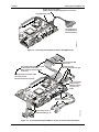
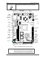
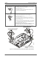
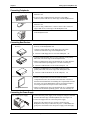
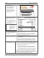
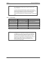
ReadyBoard 700 Single Board Computer QuickStart Guide P/N 5001723A Revision C Notice Page NOTICE No part of this document may be reproduced, transmitted, transcribed, stored in a retrieval system, or translated into any language or computer language, in any form or by any means, electronic, mechanical, magnetic, optical, chemical, manual, or otherwise, without the prior written permission of Ampro Computers, Incorporated. DISCLAIMER Ampro Computers, Incorporated makes no representations or warranties with respect to the contents of this manual or of the associated Ampro products, and specifically disclaims any implied warranties of merchantability or fitness for any particular purpose. Ampro shall under no circumstances be liable for incidental or consequential damages or related expenses resulting from the use of this product, even if it has been notified of the possibility of such damages. Ampro reserves the right to revise this publication from time to time without obligation to notify any person of such revisions. If errors are found, please contact Ampro at the address listed below on the Notice page of this document. TRADEMARKS Ampro and the Ampro logo are registered trademarks, and CoreModule, EnCore, Little Board, LittleBoard, MiniModule, ReadyBoard, ReadyBox, and ReadySystem are trademarks of Ampro Computers, Inc. All other marks are the property of their respective companies. REVISION HISTORY Revision Reason for Change Date A Initial Release Jul/04 B Updates/Changes Oct/04 C Updates/Changes Nov/04 Ampro Computers, Incorporated 5215 Hellyer Avenue San Jose, CA 95138-1007 Tel. 408 360-0200 Fax 408 360-0222 www.ampro.com © Copyright 2004, Ampro Computers, Incorporated Audience Assumptions This guide is for the person who designs computer related equipment, including but not limited to hardware and software design and implementation of the same. Ampro Computers, Inc. assumes you are qualified in designing and implementing your hardware designs and its related software into your prototype computer equipment. ii QuickStart Guide ReadyBoard 700 Contents Chapter 1 Setting Up the ReadyBoard 700....................................................................................1 Using this Guide .................................................................................................................................1 Requirements .................................................................................................................................1 What’s in the Box ...........................................................................................................................1 Setup Steps ........................................................................................................................................2 Preparations ...................................................................................................................................2 Setting Up the Workspace..............................................................................................................2 Connecting Cable Assemblies .......................................................................................................3 Connecting Peripherals ..................................................................................................................8 Connecting Boot Devices ...............................................................................................................8 Connecting the Power Supply ........................................................................................................8 Applying Power to the ReadyBoard 700 ........................................................................................9 Chapter 2 Installing ReadyBoard 700 Options ...........................................................................13 Memory Installation...........................................................................................................................13 Tools Required .............................................................................................................................13 Installation Guidelines ..................................................................................................................13 Removing the SODIMM ...............................................................................................................13 Installing the SODIMM .................................................................................................................15 CompactFlash Installation ................................................................................................................17 Tools Required .............................................................................................................................17 Installation Guidelines ..................................................................................................................17 Installing the CompactFlash Card ................................................................................................17 Removing the CompactFlash Card ..............................................................................................20 Installing Software, Drivers, and Utilities ..........................................................................................22 Appendix A Technical Support ........................................................................................................25 Contacting Support ...........................................................................................................................25 The graphic illustrations found in this manual are intended as aids in identifying the connector locations and components on the board. You may find slight variations between your board and the boards shown in this manual due to board revisions. Refer to Figure 1-4 and the ReadyBoard 700 Reference Manual for the most current board revision and the connector pin/signal tables for specific information. NOTE List of Figures Figure 1-1. Figure 1-2. Figure 1-3. Figure 1-4. Figure 1-5. Figure 1-6. Figure 2-1. Figure 2-2. Figure 2-3. Figure 2-4. Figure 2-5. ReadyBoard 700 Connector Locations ...........................................................................3 Connecting the Floppy Only Cable to ReadyBoard 700 .................................................4 Connecting IDE, Keyboard/Mouse, Parallel, and Serial Cable Assemblies ...................4 ReadyBoard 700 Connector and Pin-Locations .............................................................5 Connecting Audio In/Out and ATX Power Adapter Cable Assemblies...........................6 Connecting the Utility and USB Cable Assemblies.........................................................7 ReadyBoard 700 SODIMM Location (Bottom view) .....................................................14 Removing SODIMM from Socket..................................................................................15 Installing SODIMM into Socket .....................................................................................16 Installing the CompactFlash Card.................................................................................19 CompactFlash Card Installed........................................................................................20 ReadyBoard 700 QuickStart Guide iii Contents Figure 2-6. Removing the CompactFlash Card .............................................................................. 21 List of Tables Table 1-1. Jumper Settings ............................................................................................................. 11 Table 2-1. CompactFlash Jumper Setting ...................................................................................... 19 Table A-1. Technical Support Contact Information ......................................................................... 25 iv QuickStart Guide ReadyBoard 700 Chapter 1 Setting Up the ReadyBoard 700 Using this Guide This guide provides the most efficient way to set up your ReadyBoard 700 single board computer (SBC). The instructions provided in this guide include: • Removing the ReadyBoard 700 from the shipping container and inventorying the accessories • Connecting cables to the ReadyBoard 700 • Connecting the peripherals, boot devices, and power supply to the ReadyBoard 700 • Powering up the ReadyBoard 700 Information not provided in this QuickStart Guide includes: • ReadyBoard 700 specifications • Environmental requirements • ReadyBoard 700 connector/pin numbers and definitions • Supplied software use and programming considerations Requirements The following peripherals and devices are needed to make full use of the ReadyBoard 700. • Peripherals: (Customer Provided) ♦ PS/2 Keyboard ♦ PS/2 Mouse ♦ CRT Monitor • Power Supply: (Customer Provided) ♦ ATX or AT or Lab power supply – This type of power supply is required to provide power to the ReadyBoard 700 and the peripheral devices connected to it. An AT or Lab power supply will not have the soft-off feature of an ATX power supply • Choice of Boot Device: (Customer Provided) ♦ Floppy Disk drive ♦ IDE hard disk drive (See preinstalled OS Note in Step 16) ♦ CompactFlash card (See preinstalled OS Note in Step 16) ♦ CD-ROM • Optional Devices/Connections: (Customer Provided) ♦ Flat Panel Display (LVDS, TFT, or (D or S) STN) ♦ Ethernet ♦ USB ♦ Audio components, such as a CD-ROM or MP3 player, stereo amplifier, or a microphone What’s in the Box Refer to the QuickStart Kit Contents Sheet for a list of the cables, documents, and other items in the shipping container. ReadyBoard 700 QuickStart Guide 1 Chapter 1 Setting Up the ReadyBoard 700 Setup Steps It is important to follow the setup steps in this section in the exact order listed here, but skip any steps that do not apply to your situation. If necessary, refer to other chapters within this guide or other Ampro manuals to locate more information concerning ReadyBoard 700 installation and operation. Preparations • Locate the QuickStart Kit Contents Sheet 1) Open shipping box • Unpack the contents of the shipping box • Verify the contents of the shipping box against the QuickStart Contents Sheet included with your ReadyBoard 700 shipping box. 2) Verify contents • If anything is missing or damaged, call your sales representative or Ampro Technical Support. 3) Support documentation (ReadyBoard 700 Documentation & Support Software CD-ROM) ReadyBoard 700 QuickStart Guide This document, provided as a hardcopy, describes how to setup, install, and power up the ReadyBoard 700 found in the QuickStart Kit and is also on the ReadyBoard 700 Documentation & Software (Doc & SW) CD-ROM as a PDF file. ReadyBoard 700 Reference Manual This document describes the ReadyBoard 700 and provides detailed reference information for your ReadyBoard 700 and is located on the ReadyBoard 700 Documentation & Software (Doc & SW) CD-ROM as a PDF file. Setting Up the Workspace CAUTION To prevent damage to the electronic components on the ReadyBoard 700, do not handle the board until you have followed Electrostatic Discharge precautions. Always touch a grounded, unpainted metal surface before touching the ReadyBoard 700 or any of the components on the board. Always use an anti-static wrist strap connected to a grounding mat having staticdissipating characteristics and is attached to earth ground. 4) Select workbench location • The workbench location should be flat, clear of debris, and have a static-free mat (or the equivalent) to place the ReadyBoard 700 assembly onto for setup and operation (including the power supply and any peripherals). 5) Connect an ESD strap to your body • Connect an ESD strap between your body (wrist or ankle) and ground or the static-free mat. 6) Unpack the ReadyBoard 700 and its accessories. 2 If you do not have your own ESD strap, an ESD Kit is provided in the QuickStart Kit with an anti-static wrist strap. • Remove the ReadyBoard 700 from its protective plastic case and place it on static-free work surface. The cables provided in the QuickStart Kit are used to make external connections to the ReadyBoard 700 such as keyboard, mouse, floppy drive, IDE drives, printer, USB devices, and power. QuickStart Guide ReadyBoard 700 Chapter 1 Setting Up the ReadyBoard 700 Connecting Cable Assemblies Connect the cables provided with the ReadyBoard 700 QuickStart Kit to the respective connectors on the ReadyBoard 700. Skip any steps or cable(s) that do not apply to your situation. Infrared (J17) PC/104 (J13/14) Primary IDE (J22) Floppy/Parallel (J20) Audio In/Out (J19) (hidden) Utility (J18) (hidden) PC/104-Plus (J12) ATX Power On (J6) USB 2 & 3 (J21) ATX Power In (J4) PS/2 Keyboard/ Mouse (J16) USB 0 & 1 (J15) (USB 0 Lower) Ethernet 2 (J11) Fan (J1) GPIO (J2) CRT (J8) Serial 3 & 4 (J3) (COM 3 & 4) Serial 1 & Serial 2 (COM 1 & 2) (J5A/B) (Serial 1 Lower) RB700_03a Ethernet 1 (J10) Figure 1-1. ReadyBoard 700 Connector Locations 1) Connect the Floppy only • Connect the Floppy only cable to J20 on the edge of the ReadyBoard 700 Cable as shown in Figure 1-2. Refer also to Figures 1-1, 1-4. 2) If you want Printer only perform this step 3) Connect the Primary IDE cable The Floppy interface and Parallel Port share interface connector J20. You must choose which cable to connect to the J20, depending on the desired function; floppy only cable, or printer only cable. • If you only want a Printer (parallel only) and do not need a floppy drive, then remove the Floppy only cable and connect the Parallel (printer) only cable to J20 on the edge of the ReadyBoard 700 as shown in Figure 1-3. Refer also to Figures 1-1, 1-4. • Connect the Primary IDE cable to J22 on the edge of the ReadyBoard 700 as shown in Figure 1-3. Refer also to Figures 1-1, 1-4. This 44-pin IDE cable provides two 40-pin connectors for two IDE devices, such as an IDE hard disk drive (HDD) and a CD-ROM, etc. NOTE 4) Connect the Keyboard/ Mouse Y-cable The 44-pin to 40-pin IDE cable provided is used for a 3 ½” IDE devices (external power required). An alternate 44-pin-to-44-pin IDE cable is used for a 2 ½” HDD (no external power required). • Connect the Keyboard/Mouse Y-cable assembly to the Keyboard/Mouse port (J16) on the edge of the ReadyBoard 700 as shown in Figure 1-3. Refer also to Figures 1-1, 1-4. This cable assembly provides two connectors for the PS/2 KeyboardPS/2 Mouse shared port and each connector can be used for either device. ReadyBoard 700 QuickStart Guide 3 Chapter 1 Setting Up the ReadyBoard 700 Floppy Drive Only Cable (26-pin (J20) to 34-pin Floppy Drive Connector) Floppy/Parallel (J20) RB700_10a To Floppy Drive (34-pin Requires External Power) Figure 1-2. Connecting the Floppy Only Cable to ReadyBoard 700 Connect Primary IDE Cable to J22 One 44-pin cable/connector (J22) to two 40-pin connectors (Each requires external power to drives) Connect Parallel (Printer) only Cable to J20 Alternate 44-pin to 44-pin cable/ connector to (J6) (No external power required) 26-pin connector (J20) to 25-pin cable/connector (Printer) only Cable Connect Keyboard/ Mouse Y-Cable to J16 RB700_07aa Connect Serial 3 & 4 Cable Assembly to J3 Figure 1-3. Connecting IDE, Keyboard/Mouse, Parallel, and Serial Cable Assemblies 4 QuickStart Guide ReadyBoard 700 Chapter 1 Setting Up the ReadyBoard 700 5) Connect the Serial 3 & 4 • Connect the Serial 3 & 4 cable assembly to J3 on the edge of the Cable assembly ReadyBoard 700 as shown in Figure 1-3. Refer also to Figures 1-1, 1-4. Serial B (J3A/B) TFT/LCD RS485 Termination Serial B (J3) (COM3 & 4) GPIO (J2) (JP6, COM3 & 4) CPU Fan (J1) Clock (JP1) J1 Serial A (J5A/B) (COM1 & 2) J3 3 4 U2 U12 U1 J2 Q11 J4 1 JP6 2 Power In (J4) JP1 U32 LCD Voltage Setting (JP2) J5 U3 U4 LVDS (J7) Power-On Header (J6) J6 J26 D1 JP2 RB700QkS_01eb Y1 J7 CRT (J8) (VGA) U5 U6 J8 U33 LCD (J9) J13 J9 U7 U8 J12 Ethernet 1 (J10) J10 J14 PC/104 (J13A/B J14A/B) Lithium Battery (B1) Y2 J11 Ethernet 2 (J11) USB 0 & 1 (J15A/B) U9 CMOS Normal/ Clear (JP3) J15 Y3 U10 J16 J19 J18 U15 U13 X2 U14 D4 J20 J21 U12 JP3 JP5 J22 IR (Infrared) (J17) BT1 J17 SW1 Utility (J18) Battery Header (BT1) X1 U11 D2 PS/2 Keyboard/ Mouse (J16) PC/104-Plus (J12) JP4 CF Master/ Slave (JP4) Flash BIOS (JP5) Audio In/ Out (J19) USB 2 & 3 (J21A/B) Floppy/Parallel (J20) IDE (J22) Figure 1-4. ReadyBoard 700 Connector and Pin-Locations NOTE ReadyBoard 700 Pin-1 is shown as a black pin (square or round) in all connectors and jumpers in this illustration. In most cases, use the white dot on the cable assembly connectors to match to pin-1 on the ReadyBoard connectors as shown in Figure 1-4. In all other cases, match the red strip on the cable assemblies to pin-1 on the ReadyBoard connector. QuickStart Guide 5 Chapter 1 Setting Up the ReadyBoard 700 Skip any of the following steps that do not apply to your situation. 6) Connect the Audio In/Out Cable Assembly • Connect the Audio In/Out cable assembly to J19 near the edge of the ReadyBoard 700 as shown in Figure 1-5. Refer also to Figures 1-1, 1-4. The Earphone connector on the Audio cable assembly is not connected on the ReadyBoard 700. 7) Connect the ATX Adapter Cable Assembly • Connect the ATX Power Adapter cable assembly to J4 and J6 on the edge of the ReadyBoard 700 as shown in Figure 1-5. Refer also to Figures 1-1, 1-4. The ATX power adapter is separated into two connectors to provide support for non-ATX power supplies (Power Input (J4) and Power Control (J6)). Connector (J4) only provides the input voltages (+5V & optional +12V) and ground, while connector (J6) provides the power on signal and the standby voltage (+5V). • If you do not use an ATX power supply, you will have to provide the standby voltage (+5V) to J6 for the soft off function. Typically, this means shorting the +5V (pin-1, J4) to J6, pin-1. Connect the Audio In/Out Cable Assembly to J19 Connect the ATX Power Adapter Cable Assembly to J4 and J6 J19 J6 RB700_08a J4 Note: The PS/2 Keyboard/Mouse connector is shown removed for clarity. Figure 1-5. Connecting Audio In/Out and ATX Power Adapter Cable Assemblies 6 QuickStart Guide ReadyBoard 700 Chapter 1 Setting Up the ReadyBoard 700 8) Connect USB 2 & 3 Cable Assembly • Connect the USB 2 & 3 cable assembly to J21 on the edge of the ReadyBoard 700 as shown in Figure 1-6. Refer also to Figures 1-1, 1-4. 9) Connect Utility Cable Assembly • Connect the Utility cable assembly to J18 near the edge of the ReadyBoard 700 as shown in Figure 1-6. Refer also to Figures 1-1 and 1-4. NOTE ♦ The Green Power-On switch uses Pins-1 & -2 of the Utility Connector. ♦ The Red Reset switch uses Pins-2 and -3 of the Utility Connector. The Power-On switch turns the ReadyBoard 700 to an On condition, if your are using an ATX power supply. Normally, the operating system (OS) will turn Off the ReadyBoard during the OS shut down process. However, if you need to turn off the ReadyBoard, pressing and holding the Power-On button for more than 4-6 seconds will turn the ReadyBoard 700 to an Off state. Connect USB 2 & 3 Cable Assembly to J21 Note: Keyboard/Mouse connector shown removed for clarity. RB700_09a Connect Utility Cable Assembly to J18 Figure 1-6. Connecting the Utility and USB Cable Assemblies ReadyBoard 700 QuickStart Guide 7 Chapter 1 Setting Up the ReadyBoard 700 Connecting Peripherals 10) Connecting the peripherals • Connect the keyboard to one of the free PS/2 connectors on the Y-cable attached to J16. • If your are using a USB keyboard, connect it to the USB 0 connector (lower USB on J15) on the edge of the ReadyBoard 700. • Connect the mouse cable to the other PS/2 connector on the Y-cable attached to J16. • If your are using a USB mouse, connect it to the USB 1 connector (upper USB on J15) on the edge of the ReadyBoard 700. • Connect the CRT monitor to the video connector at J8 on the edge of the ReadyBoard 700. Connecting Boot Devices 11) Connect the OS boot device(s) • Use one of the four options listed here to connect a (OS) boot device(s) to the ReadyBoard 700: a. Connect a floppy disk drive to the floppy drive only cable connected to J20 on the edge of the ReadyBoard 700. Or Connect a USB floppy drive to one of the USB ports, Or b. Connect an IDE hard disk drive to a free connector on the primary IDE cable (J22) on the edge of the ReadyBoard 700. • Ampro recommends not using a preinstalled OS on a hard disk drive to boot and load the operating system. See Note with Step 16. Or Connect a USB hard drive to one of the USB ports, Or c. Connect a CD-ROM drive to an available connector on the primary IDE cable (J22) on the edge of the ReadyBoard 700. Or Connect a USB CD-ROM to one of the USB ports, Or d. Install a CompactFlash card with a bootable OS into the CompactFlash socket (J23) located on the underside of the board. CompactFlash Card Instructions and limitations for installing the CompactFlash card into the socket (J23) on the ReadyBoard 700 are provided in Chapter 2, Installing ReadyBoard 700 Options later in this manual. • Ampro recommends not using a preinstalled OS on a CompactFlash card to boot and load the operating system. See Note with Step 16. Connecting the Power Supply 12) Connect power supply • Connect the ATX power supply to the ATX power adapter connectors at J4 and J6 on the edge of the ReadyBoard 700. See Figure 1-4. • Connect all support devices to the ATX power supply. Ensure all of the support devices you have connected to the ReadyBoard 700 (except a CRT and a 44-pin, 2 ½” IDE HDD) have good power connections to the ATX power supply or the lab supply. 8 QuickStart Guide ReadyBoard 700 Chapter 1 Setting Up the ReadyBoard 700 Applying Power to the ReadyBoard 700 13) Check/Set the Power Supply Input Voltage • If the ATX power supply or lab supply uses auto-ranging operation at 50/60Hz, skip this step. • Check the input voltage switch on the ATX power supply located on the rear of the ATX power supply just below the power connector. 14) Verify the Jumper Settings The input voltage switch typically has two positions: 115 or 230 volts – 115 volts is default position. • Check the jumper settings just in case a jumper has shifted during shipping. • Refer to Figure 1-4 for the jumper locations and the Table 1-1, located at the end of this chapter for the default jumper settings. • Plug the CRT monitor’s power cord into an AC outlet and turn on the monitor. 15) Power up the ReadyBoard 700 • Plug the ATX power supply’s power cord into the AC outlet. • Turn the ATX power supply’s power switch to On. • Press the Green Power-On switch connected to the Utility connector (J18) before continuing. 16) Verify the ReadyBoard 700 powers-up satisfactorily • Verify the ReadyBoard 700 passes POST successfully. • If a bootable device, or the desired operating system is not loaded on one of the boot devices (floppy drive or CD-ROM) prior to power up, you will see an error message, “No bootable device available,” near the end of the boot process. The boot process stops until you intervene by selecting from the following options: ♦ Press R (or the Reset switch) to Reboot the system ♦ Press S (to enter BIOS Setup) for Setup, or skip to Step 17. ♦ Turn off the power switch on the ATX power supply, and/or… ♦ Connect a bootable device to the ReadyBoard 700, Reboot the system, and then skip to Step 17. NOTE NOTE Ampro does not recommend using a hard disk drive or CF card with a preinstalled OS from another model computer to boot the ReadyBoard 700. This has proven to cause problems or provide unreliable operation. Use a bootable device (floppy or CD-ROM) to install the desired OS and drivers onto the hard drive (or CF), while still attached to the ReadyBoard 700. Refer to Step 19. For the most current BIOS Information, refer to the Hardware Release Notes provided as hard copy in the shipping container. 17) Enter BIOS Setup. • Press the <Del> key during POST, or S to enter BIOS Setup. • Use BIOS Setup during the initial boot to set the desired options (time and date, alter the boot order of the floppy drive, CD-ROM, or hard disk drive, etc.). • Refer to the next step to alter the boot sequence, while in Setup. 18) Alter Boot Order, only if needed ReadyBoard 700 • If you need to alter the boot sequence to select a bootable device, perform the items listed in this step. QuickStart Guide 9 Chapter 1 Setting Up the ReadyBoard 700 a) Select the BIOS and Hardware Settings menu as shown in the figure to the right and press Enter. Ampro Setup Util The sub-steps listed here show you how to change the Boot Sequence while in the BIOS Setup Utility. > BIOS and Hardware Settings < ETX700enterBIOS Reload Initial Settings Load Factory Default Settings Exit, Saving Changes Exit, Discarding Changes b) Select the first drive in the Boot Order as highlighted to the right. Ampro Setup Utility for ReadyBo NOTE The CD-ROM or CompactFlash (CF) must be listed in Drive Assignment and the Boot Order to be recognized by the BIOS. 1.44 MB, 3.5” (none) HDD on Pri Master CDROM on Pri Slave (none) (none) (none) Drive A: < Drive C: CDROM (none) (none) RB550BtSeqa [Drive Assignment] Drive A Drive B Drive C Drive D Drive E Drive F Drive G [Boot Order] > Boot 1st Boot 2nd Boot 3rd Boot 4th Boot 5th This example assumes Drive A is a 3 ½” floppy drive, Drive C is an IDE HDD, and Drive D is an IDE CD-ROM. c) Use the Arrow keys and PU/PD keys to change the CD-ROM into the First Boot Device in the boot order. • Use the PU/PD keys to change from Drive A: (Floppy) to [CDROM] in the boot order. d) • Check the other BIOS settings related to the floppy drive before exiting BIOS setup. • You will need to change Drive A: (Floppy) to the Third Boot Device or another boot device, to keep it in the boot sequence without a break in the boot device order. Exit and Save changes. 19) Install the desired Operating System (OS) The other settings in BIOS Setup that also affect the floppy drive during the boot sequence or normal operation are: Floppy over Parallel, Floppy Seek, Floppy Swap, and Floppy (On Board Controllers). These fields may need to be checked or changed too. • Locate the desired Operating System (OS) diskette(s) or CD-ROM and follow the manufacturer’s instructions for installing the OS and the necessary drivers onto your boot and operating storage device (Hard Disk Drive, CompactFlash, etc.). ♦ For Windows Operating Systems, some of the necessary drivers may be found on the manufacturer’s installation CD-ROM. For other Operating Systems, some or all of the necessary drivers may be found on the manufacturer’s diskette(s) or CD-ROM. • If you require drivers that are not available on the OS manufacturer’s diskette(s) or CD-ROM, refer to Installing Software, Drivers, and Utilities in Chapter 2 and the ReadyBoard 700 software directory on the ReadyBoard 700 Doc & SW CD-ROM for instructions. ♦ 10 QuickStart Guide ReadyBoard 700 Chapter 1 NOTE Setting Up the ReadyBoard 700 The ReadyBoard 700 ships from the factory configured for CRT support only. Ampro provides LVDS/LCD/TFT support for flat panels with specific resolutions. If you have questions about the flat panels, contact Technical Support through Virtual Technician (http://ampro.custhelp.com) for help in setting up the flat panel configurations. Refer also to the ReadyBoard 700 Reference Manual and the Software Release Notes for additional instructions and information when customizing the BIOS to a particular flat panel. Table 1-1. Jumper Settings Jumper # Installed Removed/Installed JP1 – TFT/LCD Clock Clock Invert (pins 1-2) Clock (pins 2-3) Default JP2 – LCD Voltage Type Enable +3.3V (pins 1-2) Default Enable +5V (pins 2-3) JP3 – CMOS Normal/Clear Normal (pins 1-2) Default Clears Time & Date only (pins 2-3) JP4 – CF Master/Slave Master (pins 1-2) Default Slave (removed) JP5 – Flash BIOS Internal (pins 1-2) Default External (removed) JP6 – COM3 RS485 Termination (pins 1-2) No Termination (removed) Default JP6 – COM4 RS485 Termination (pins 3-4) No Termination (removed) Default NOTE ReadyBoard 700 The CMOS Normal/Clear jumper (JP3) only resets the Time and Date of the BIOS to Jan 1, 1980; 00:00. If you need to reset the BIOS to the defaults because you can’t boot the system, use the Oops! Jumper referenced in the ReadyBoard 700 Reference Manual. The Oops! Jumper prevents the current BIOS settings in Flash memory from being loaded, forcing the BIOS to use the default settings, but does not change the Time & Date in the BIOS. The ReadyBoard 700 Reference Manual provides a more detailed discussion of how to create and use the Oops! Jumper. QuickStart Guide 11 Chapter 1 12 Setting Up the ReadyBoard 700 QuickStart Guide ReadyBoard 700 Chapter 2 Installing ReadyBoard 700 Options The procedures in the first part of this chapter describe how to install or remove the ReadyBoard 700 SBC (Single Board Computer) options onto or from the board, including the SODIMM and the CompactFlash card. Brief instructions for accessing and using the ReadyBoard 700 Doc & SW (Documentation and Software) CD-ROM and a brief description for loading supported Operating Systems is also provided at the end of this chapter. Memory Installation The ReadyBoard 700 uses a single SODIMM socket available on the underside of the board. The ReadyBoard 700 supports PC 133 (133MHz, 7.5ns) or PC 100 (100MHz, 10ns), 3.3V, 144-pin, SDRAM SODIMM. NOTE Ampro recommends using only PC 133 (133MHz), 3.3V, 7.5ns, 144-pin, SDRAM SODIMM, but PC 100 (100MHz, 10ns) will function. PC 133 provides the best performance for the 650MHz Celeron and 933MHz Pentium processors. Tools Required Use an anti-static service kit (or the equivalent) to remove or install the SODIMM. An anti-static service kit should include a static-dissipating work surface, a chassis clip lead, and a wrist or ankle strap. Installation Guidelines • When handling a SODIMM, observe anti-static discharge precautions to avoid damage. • The ReadyBoard 700 uses PC 133 (133MHz) or PC 100 (100MHz), SDRAM SODIMMs, which are electrically different from EDO SODIMMs. • The following SODIMMs sizes are available from Ampro: 32MB, 64MB, 128MB, 256MB, or 512MB. • The ReadyBoard 700 supports up to 512MB of memory in the SODIMM socket. Removing the SODIMM Use this procedure to remove the SODIMM from the SODIMM socket on the ReadyBoard 700. 1. If the ReadyBoard 700 is already connected to power and operating, power down the system. CAUTION To prevent damage to the ReadyBoard 700 and the SODIMM, ensure the power switch on the ATX power supply is turned off and the power cord has been removed from the power source. The typical ATX power supply will continue to provide standby current to the board until the power cord is disconnected. 2. Disconnect the ATX power supply’s power cord from the power source. 3. Disconnect any cables that would prevent you from turning the ReadyBoard 700 over exposing the bottom of the board. 4. Turn the ReadyBoard 700 over to access the bottom of the board and lay it on a flat anti-static surface. See Figures 2-1 and 2-2. ReadyBoard 700 QuickStart Guide 13 Chapter 2 Installing ReadyBoard 700 Options To prevent damage to the SODIMM, do not touch the SODIMM until you have discharged yourself and followed good Electrostatic Discharge principals. The SODIMMs are sensitive to static electricity and can be easily damaged by improper handling. Do the following when handling a SODIMM: CAUTION Leave the SODIMM in the anti-static bag until you are ready to install it. Always use an anti-static wrist/ankle strap and a grounding mat connected to ground. Before you remove a SODIMM from the anti-static bag, touch a grounded, unpainted metal surface to discharge any static electricity. U27 L1 U28 U29 5. Locate the SODIMM socket (DIMM1) on the bottom of the ReadyBoard 700. See Figure 2-1. D12 U26 Q10 Q8 U25 D11 Q9 Q6 D10 U24 U23 Q7 Q5 D9 SODIMM Socket (DIMM1) U22 SODIMM DIMM1 U21 F4 F3 U20 Retaining Latches (2) J23 D8 F2 Q4 RB700_02c Q3 D7 U19 F1 U16 U17 D5 Q2 D6 Figure 2-1. ReadyBoard 700 SODIMM Location (Bottom view) 6. Open both retaining latches to release the SODIMM from the socket. See Figure 2-2. The SODIMM will spring up to a 45° angle to the board once you open both retaining latches. If the SODIMM does not spring up to a 45° angle, then the retaining latches have not released the SODIMM remove from the socket. 7. Using the card edges, lift the SODIMM completely away from the socket. See Figure 2-2. 8. Place the SODIMM on an anti-static surface or in an anti-static bag. NOTE 14 If you remove the SODIMM and restore power without a SODIMM installed, your system will not work properly and you will not see a display. QuickStart Guide ReadyBoard 700 Chapter 2 Installing ReadyBoard 700 Options SODIMM Socket (DIMM1) SODIMM RB700_05a 45° Angle Retaining Latches Figure 2-2. Removing SODIMM from Socket Installing the SODIMM If you want to install a larger size SODIMM or replace the existing SODIMM, refer to the following procedure. 1. Prepare the ReadyBoard 700 for installation: ♦ If the ReadyBoard 700 is already prepared for SODIMM installation, with the power turned off, the power cord disconnected, and an empty SODIMM socket, skip to Step 4. ♦ If the ReadyBoard 700 is operating, power down the system and continue with next step. CAUTION To prevent damage to the ReadyBoard 700 and the SODIMM, ensure the power switch on the power supply is turned off and the power cord has been removed from the power source. The typical AT power supply will continue to provide standby current to the board until the power cord is disconnected. 2. Disconnect the ATX power supply’s power cord from the power source. CAUTION To prevent damage to the SODIMM, do not touch the SODIMM until you have discharged yourself and followed good Electrostatic Discharge principals. The SODIMMs are sensitive to static electricity and can be easily damaged by improper handling. Do the following when handling a SODIMM: Leave the SODIMM in the anti-static bag until you are ready to install it. Use an anti-static wrist/ankle strap and a grounding mat connected to ground. Before you remove a SODIMM from the anti-static bag, touch a grounded, unpainted metal surface to discharge any static electricity. 3. Disconnect any cables that would prevent you from turning the ReadyBoard 700 over exposing the bottom of the board. 4. Turn the ReadyBoard 700 over to access the bottom of the board and lay it on a flat anti-static surface. See Figures 2-1 and 2-3. ReadyBoard 700 QuickStart Guide 15 Chapter 2 Installing ReadyBoard 700 Options 5. Remove the existing SODIMM from the SODIMM socket before continuing. Refer to the Step 4 in the proceeding procedure, Removing the SODIMM, and follow the remaining steps in that procedure before continuing with the next step in this procedure. 6. Remove the SODIMM from its protective bag, handling the SODIMM by its edges. NOTE Ampro recommends using only PC 133 (133MHz), 3.3V, 7.5ns, 144-pin, SDRAM SODIMM, but PC 100 (100MHz) will function. PC 133 provides the best performance for the 650MHz Celeron or 933MHz Pentium processors. 7. Ensure there is nothing in the SODIMM socket that would prevent its installation. 8. Insert the SODIMM into the socket at 45° angle to the bottom of the ReadyBoard 700 with the components facing up. See Figure 2-3. The SODIMM card edge and socket are keyed to install the SODIMM into the socket in only one direction. SODIMM Socket (DIMM1) SODIMM RB700_05b 45° Angle Retaining Latches Alignment Notch Figure 2-3. Installing SODIMM into Socket 9. Press the edges of the SODIMM down between the latches until the latches snap into place. See Figure 2-3. The latches should open to accept the SODIMM without any resistance. If you encounter any resistance, you may not have inserted the SODIMM far enough into the socket. 10. If the retaining latches do not close completely on the SODIMM, remove it and repeat Steps 6 to 7. 11. Turn the ReadyBoard 700 back over onto the bottom of the board, placing it on the work surface. 12. Reconnect any cables you disconnected earlier and verify all other connections to the ReadyBoard 700 are still connected. 13. Reconnect the ATX power supply’s power cord to the power source. 14. Restore power to the ReadyBoard 700 and observe the boot screen for new memory recognition. If the system does not boot or there is a problem recognizing the new memory, the new SODIMM could be defective or the SODIMM was not properly installed or recognized. 16 QuickStart Guide ReadyBoard 700 Chapter 2 Installing ReadyBoard 700 Options CompactFlash Installation The CompactFlash interface allows you to substitute solid-state flash memory cards for a conventional hard disk drive. Any of the supported operating system, utilities, drivers, and application programs can easily be run from the CompactFlash card without modification. NOTE You may use Type I or Type II CompactFlash cards from commercially available suppliers, but check for compatibility with UDMA 100 IDE hard disk drives. Older CompactFlash cards that are not compatible with UDMA 100 IDE hard disk drives will cause system hangs. Tools Required The following tools are needed to remove and install the CompactFlash card onto or off of the ReadyBoard 700 SBC. • Anti-static service kit - Use a complete anti-static service kit (or the equivalent) to remove or install the CompactFlash card. A complete anti-static service kit should include a staticdissipating work surface, a chassis clip lead, and a wrist or ankle strap. Installation Guidelines The ReadyBoard 700 only supports the CompactFlash card on the Secondary IDE channel of the EIDE disk controller. • Configure the CompactFlash card as [HDD/CF on Sec Master/Slave] in the “Drive Assignment Order” and “Boot Order” as a hard disk drive in the BIOS Setup Utility. • Use the Master/Slave jumper (JP4) to determine the Master/Slave status of the CompactFlash Card. • The ReadyBoard 700 only supports +5V tolerant CompactFlash cards. Newer CompactFlash cards will typically work with either 5V or +3.3V systems. These newer CompactFlash cards sense the input voltage and adjust accordingly. NOTE Ampro recommends not using a CompactFlash card with a preinstalled OS from another model computer to boot the ReadyBoard 700. This has proven to cause problems or provide unreliable operation. Use a bootable device (floppy or CD-ROM) to load the desired OS onto CompactFlash card and then the drivers, while attached to the ReadyBoard 700. Once the OS has been installed correctly on the CompactFlash card, it can be used to boot the ReadyBoard 700 without difficulty. Installing the CompactFlash Card This procedure describes disconnecting all of the cables to turn the ReadyBoard 700 over, exposing the bottom of the board to install or remove the CompactFlash card. However, depending on how you have the ReadyBoard 700 mounted and the location of the socket near the edge of the board, this may not be necessary. It is possible to install or remove the CompactFlash card without disconnecting all of the cables and turning the board over, but doing so provides the safest method of checking the condition of the CompactFlash socket before installing the CompactFlash card. You may have to remove the two Ethernet cables and the USB cables to have full access to the CompactFlash socket and card, but you must power down the system before installing or removing the CompactFlash card. ReadyBoard 700 QuickStart Guide 17 Chapter 2 Installing ReadyBoard 700 Options To simplify this procedure, power down the system and disconnect the two Ethernet cables and the USB cables, which will allow full access to the CompactFlash socket and card. If you have the ReadyBoard securely mounted, with enough clearance, it is not necessary to turn the board over to access the CompactFlash card. NOTE However, the procedures described here and on the following pages provide the safest method of checking the condition of the CompactFlash socket before installing the CompactFlash card. 1. ReadyBoard 700 preparation: ♦ If the ReadyBoard 700 is already prepared for CompactFlash installation, with power disconnected, skip to Step 5. ♦ If the ReadyBoard 700 is connected to power and operating, power down the system and continue with next step. CAUTION To prevent damage to the ReadyBoard 700, ensure the power supply is turned off and the power cord has been removed from the power source. The typical ATX power supply will continue to provide standby current to the board until the power cord is disconnected. 2. Disconnect the ATX power supply’s power cord from the power source. CAUTION To prevent damage to the ReadyBoard 700 or the CompactFlash card, do not touch either one until you have discharged yourself and have followed good Electrostatic Discharge principals. The ReadyBoard 700 and the CompactFlash card are sensitive to static electricity and can be easily damaged by improper handling. Do the following when handling either one: Leave the CompactFlash in the anti-static bag until you are ready to install it. Always use an anti-static wrist/ankle strap and a grounding mat connected to ground. Before you remove a CompactFlash from the anti-static bag, touch a grounded, unpainted metal surface to discharge any static electricity. 3. Disconnect any cables that would prevent you from turning the ReadyBoard 700 over exposing the bottom of the board. 4. Turn the ReadyBoard 700 over to access the bottom of the board and lay it on a flat anti-static surface. See Figure 2-4. 5. Check for bent pins or debris on the pins of the CompactFlash socket (J23). 6. Remove the CompactFlash card from its protective bag, handling the CompactFlash by its edges. CAUTION To prevent damage to your CompactFlash card, do not insert a +3.3V only CompactFlash card. The ReadyBoard 700 only supports +5V or Universal (+5V tolerant) CompactFlash cards. If you are using a newer CompactFlash card, it will typically work with either 5V or +3.3V. The newer CompactFlash cards sense the input voltage and adjust accordingly. 18 QuickStart Guide ReadyBoard 700 Chapter 2 Installing ReadyBoard 700 Options 7. Insert the CompactFlash card into the socket provided by the tabs on the protective cover as shown in Figure 2-1. The CompactFlash card edges and the socket are keyed to install in only one orientation. Insert CompactFlash Card Pin-1 Marker Lip or Catch Edge CompactFlash Socket (J23) ReadyBoard 700 (Bottom view) RB700_06a Keyed Slot (2) Figure 2-4. Installing the CompactFlash Card 8. Push the CompactFlash card into the socket until it is firmly into the socket and mates with the pins. See Figures 2-4 and 2-5. 9. Turn the ReadyBoard 700 back over onto the bottom of the board, placing it on the work surface. 10. Reconnect any cables you disconnected earlier and verify all other connections to the ReadyBoard 700 are still connected. 11. Set the Master/Slave jumper (JP4) to the master/salve status before continuing. See Table 2-1 and Figure 1-4. Table 2-1. CompactFlash Jumper Setting Jumper # Installed Removed/Replaced JP4 – CF Master/Slave Master (pins 1-2) Default Slave (removed) 12. Plug the ATX power supply’s power cord into the AC power source and restore power. 13. Go into the BIOS Setup Utility and change the settings for the CompactFlash Card placing it in the Drive Assignment and the Boot Order. NOTE The CompactFlash must be listed in Drive Assignment and the Boot Order to be recognized by the BIOS. The CompactFlash can be listed in any of the drive positions. However, the BIOS does not support a break in the drive order, that is, Drive C can not be listed as [none] when the boot device is Drive D. ReadyBoard 700 QuickStart Guide 19 D12 U26 Q10 Q8 U25 D11 Q9 RB700_02da U28 L1 U27 Installing ReadyBoard 700 Options U29 Chapter 2 Q6 D10 U24 U23 Q7 Q5 D9 CompactFlash Socket (J23) U22 CompactFlash Card Installed DIMM1 U21 F4 F3 U20 J23 D8 F2 Q4 ReadyBoard 700 (Bottom view) Q3 D7 U19 F1 U16 U17 D5 Q2 D6 Figure 2-5. CompactFlash Card Installed Removing the CompactFlash Card 1. ReadyBoard 700 preparation: ♦ If the ReadyBoard 700 is already prepared for CompactFlash card removal, with power disconnected, skip to Step 5. ♦ If the ReadyBoard 700 SBC is already connected and operating, power down the system and continue with the next step. CAUTION To prevent damage to the ReadyBoard 700 or the CompactFlash, ensure the power supply is turned off and the power cord has been removed from the power source. The typical ATX power supply will continue to provide standby current to the board until the power cord is disconnected. 2. Disconnect the ATX power supply’s power cord from the power source. 20 QuickStart Guide ReadyBoard 700 Chapter 2 Installing ReadyBoard 700 Options CAUTION To prevent damage to the ReadyBoard 700 or the CompactFlash card, do not touch either one until you have discharged yourself and have followed good Electrostatic Discharge principals. The ReadyBoard 700 and CompactFlash cards are sensitive to static electricity and can be easily damaged by improper handling. Do the following when handling the CompactFlash cards: Leave the CompactFlash in the anti-static bag until you are ready to install it. Always use an anti-static wrist/ankle strap and a grounding mat connected to ground. Before you remove a CompactFlash card from the anti-static bag, touch a grounded, unpainted metal surface to discharge any static electricity. 3. Disconnect any cables that would prevent you from turning the ReadyBoard 700 over exposing the bottom of the board. 4. Turn the ReadyBoard 700 over to access the bottom of the board and lay it on a flat anti-static surface. See Figure 2-6. 5. Grasp the two sides of the CompactFlash card or the lip (catch edge) and gently pull it from the CompactFlash socket and place on anti-static surface or in anti-static bag. Remove CompactFlash Card Lip or Catch Edge Pin-1 Marker CompactFlash Socket (J23) ReadyBoard 700 (Bottom view) RB700_06b Keyed Slot (2) Figure 2-6. Removing the CompactFlash Card 6. Turn the ReadyBoard 700 back over onto the bottom of the board, placing it on the work surface. 7. Reconnect any cables you disconnected earlier and verify all other connections to the ReadyBoard 700 are still connected. 8. If you are not replacing the CompactFlash card with another CompactFlash card, ensure you have set JP4 to the correct setting (Master/Slave) before continuing. See Table 2-1 and Figure 1-4. 9. Plug the ATX power supply’s power cord into the AC power source and restore power. ReadyBoard 700 QuickStart Guide 21 Chapter 2 Installing ReadyBoard 700 Options Installing Software, Drivers, and Utilities To install the operating system and respective software drivers, refer to the following procedure. 1. Install the desired Operating System (OS) and related drivers from the manufacturer’s diskette(s) or CD-ROM. Follow the manufacturer’s instructions to install the desired OS and respective drivers. ♦ For Windows Operating Systems, some of the necessary drivers may be found on the manufacturer’s installation diskette or CD-ROM. If more software drivers are needed, refer to the ReadyBoard 700 Doc & SW CD-ROM. ♦ For other Operating Systems, some or all of the necessary drivers may be found on the manufacturer’s installation diskette(s) or CD-ROM. If not, refer to the ReadyBoard 700 Doc & SW CD-ROM. 2. Run the ReadyBoard 700 Doc & SW CD-ROM to access the ReadyBoard documentation, various utilities, and OS drivers not on the manufacturer’s diskette(s) or CD-ROM. The ReadyBoard 700 Doc & SW CD-ROM will operate on any Windows PC, allowing you to view, download, or print the contents of the CD-ROM. This includes the ReadyBoard 700 QuickStart Guide, ReadyBoard 700 Reference Manual, Release Notes, software drivers and various utilities. NOTE You must have an Internet browser to view the main menu and make selections (examples: Microsoft Internet Explorer 4.x, or greater, Netscape Navigator version 4.x, or greater, or the equivalent on a PC). Software download links are provided for Adobe Acrobat Reader version 4.x or greater to view the manuals and documents. An Internet connection is required for the Adobe Acrobat link or access to the Ampro web site. The ReadyBoard 700 Doc & SW CD-ROM should auto-start, but if it does not, go to the root level of the CD-ROM and locate the index.htm by: a. Selecting Run from the Start menu in any Windows PC. b. Browsing the contents of the CD-ROM until you find the index.htm at the root level. c. Select this file and press OK to start the CD-ROM. The CD-ROM starts and opens the main menu of the CD-ROM. 3. Select from the directories as shown below: ♦ ReadyBoard 700 Documentation (Release Notes, ReadyBoard 700 Reference Manual and QuickStart Guide) ♦ ReadyBoard 700 Software (Board Support Packages for supported operating systems, BIOS file, drivers, and miscellaneous source code examples) ♦ Need Adobe Acrobat? (Link to Adobe Acrobat Reader; requires Internet connection) There are directories and subdirectories under these topics that should provide you with the needed manuals, utilities, and tools not explained earlier. 22 QuickStart Guide ReadyBoard 700 Chapter 2 Installing ReadyBoard 700 Options 4. Install any special OS drivers not found on the manufacturer’s diskette(s) or CD-ROM. Refer to the directories on the ReadyBoard 700 Doc & SW CD-ROM for instructions on installing the special drivers for the desired OS. If the desired drivers can not be found, contact Ampro through the Virtual Technician on the web site with a request for the driver(s). Use the Link to Ampro’s web site on the ReadyBoard 700 Doc & SW CD-ROM. Refer also to the Appendix A, Technical Support for more information. 5. Install any utilities or other development tools you may need from the ReadyBoard 700 Doc & SW CD-ROM. Refer to the directories on the ReadyBoard 700 Doc & SW CD-ROM for instructions on installing and using the utilities or development tools for the desired OS. ReadyBoard 700 QuickStart Guide 23 Chapter 2 24 Installing ReadyBoard 700 Options QuickStart Guide ReadyBoard 700 Appendix A Technical Support Contacting Support Ampro Computers, Inc. provides a number of methods for contacting Technical Support as listed below in Table A-1. Requests for support through the Virtual Technician are given the highest priority and usually will be addressed within one working day. • Ampro Virtual Technician – This is a comprehensive support center designed to meet all your technical needs. This service is free and available 24 hours a day through the Ampro web site at http://ampro.custhelp.com. This includes a searchable database of Frequently Asked Questions, which will help you with the common information requested by most customers. This is a good source of information to look at first for your technical solutions. However, you must register online before you can log in to access this service. • Personal Assistance – You may also request personal assistance by going to the "Ask a Question" area in the Virtual Technician. Requests can be submitted 24 hours a day, 7 days a week. You will receive immediate confirmation that your request has been entered. Once you have submitted your request you can go to the "My Stuff" area and log in to check status, update your request, and access other features. • Embedded Design Resource Center – This service is also free and available 24 hours a day at the Ampro web site at http://www.ampro.com. However, you must be registered online before you can login to access this service. The Embedded Design Resource Center was created as a resource for embedded system developers to share Ampro's knowledge, insight, and expertise gained from years of experience. This page contains links to White Papers, Specifications, and additional technical information. Table A-1. Technical Support Contact Information Method Contact Information Virtual Technician http://ampro.custhelp.com Web Site http://www.ampro.com Standard Mail Attn: Technical Support Ampro Computers, Incorporated 5215 Hellyer Avenue San Jose, CA 95138-1007, USA ReadyBoard 700 QuickStart Guide 25 Appendix A 26 Technical Support QuickStart Guide ReadyBoard 700