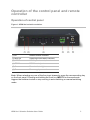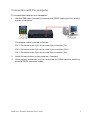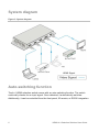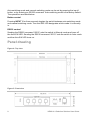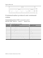
1
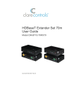
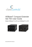
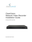
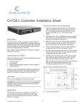
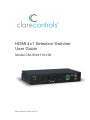
HDMI 4x1 Selection Switcher
User Guide
Model CM-SW4110-HD
Doc ID 2013-12-356 • Rev 01
Copyright
© 18DEC13 Clare Controls, Inc. All rights reserved.
This document may not be copied in whole or in part or otherwise
reproduced without prior written consent from Clare Controls, Inc.,
except where specifically permitted under US and international
copyright law.
Trademarks and
patents
The HDMI 4x1 Selection Switcher User Guide,
Model CM-SW4110-HD name is a trademark of Clare Controls, Inc.
Other trade names used in this document may be trademarks or
registered trademarks of the manufacturers or vendors of the
respective products.
Manufacturer
Version
Contact information
Clare Controls, Inc.
7519 Pennsylvania Ave., Suite 104, Sarasota, FL 34243, USA
This document applies to HDMI 4x1 Selection Switcher User Guide,
Model CM-SW4110-HD version 1.
For contact information, see www.clarecontrols.com.
Content
Important information...ii Limitation of liability...ii Introduction...1 Features...1 Package contents...1 Specifications...2 Operation of the control panel and remote controller...3 Operation of control panel...3 Operation of the remote controller...4 Interface connections...4 Connection with the control system...4 Connection with the computer...5 System diagram...6 Auto-switching function...6 Panel drawing...8 Communication protocol and command codes...9 Troubleshooting and maintenance...10 Safety operation...11 After-sales service...12 HDMI 4x1 Selection Switcher User Guide
i
Important information
Limitation of liability
To the maximum extent permitted by applicable law, in no event will Clare
Controls, Inc. be liable for any lost profits or business opportunities, loss of use,
business interruption, loss of data, or any other indirect, special, incidental, or
consequential damages under any theory of liability, whether based in contract,
tort, negligence, product liability, or otherwise. Because some jurisdictions do not
allow the exclusion or limitation of liability for consequential or incidental damages
the preceding limitation may not apply to you. In any event the total liability of
Clare Controls, Inc. shall not exceed the purchase price of the product. The
foregoing limitation will apply to the maximum extent permitted by applicable law,
regardless of whether Clare Controls, Inc. has been advised of the possibility of
such damages and regardless of whether any remedy fails of its essential
purpose.
Installation in accordance with this manual, applicable codes, and the instructions
of the authority having jurisdiction is mandatory.
While every precaution has been taken during the preparation of this manual to
ensure the accuracy of its contents, Clare Controls, Inc. assumes no responsibility
for errors or omissions.
ii
HDMI 4x1 Selection Switcher User Guide
Introduction
Use the HDMI 4x1 selection switcher to allow multiple HDMI source devices to be
routed to a single, available HDMI input on a display. This can reduce the number of
HDMI cables required to run to the display. The switch can be controlled using the
front panel buttons, IR remote (included), or RS232 control.
The switch is a high performance HDMI device supporting resolutions up to 1920 x
1200 at 60 Hz, and 1080p. It supports EDID and DDC, and is HDCP and HDTV
compliant. It can be used in both residential and commercial applications to allow a
single available HDMI to view a variety of sources.
Features
•
Supports Extended Display Identification Data (EDID) and Display Data Channel
(DDC)
•
HDTV compatible with high definition transmission resolution up to 1920 x 1200 at
60 Hz (maximum), and 1080p.
•
HDCP compliant, supporting DVI/HDMI 1.4a
•
Built-in gain compensation technology
•
Switching control from the front panel, RS232, and the IR remote
Package contents
•
1 x CM-SW4110-HD 4x1 HDMI selection switch
•
2 x removable mounting brackets
•
4 x screws
•
1 x IR remote control
•
1 x power adapter (5 VDC)
•
1 x RS232 cable
•
1 x user manual
Notes: Please verify that the product and all the accessories are included. If not,
contact your dealer.
HDMI 4x1 Selection Switcher User Guide
1
Specifications
Video Input
Video Output
Input
HDMI type
Output type
HDMI
Input connector
Female HDMI
Output connector
Female HDMI
Input level
T.M.D.S. 2.9 V / 3.3 V
Output level
T.M.D.S. 2.9 V / 3.3 V
Input impedance
50Ω
Output impedance
50Ω
Resolution range
Up to 1920 × 1200 or
1080P at 60 Hz
Bandwidth
6.75 Gb/s
Switching speed
200 ns (maximum)
Input / Output level
T.M.D.S. 2.9V / 3.3 V
Gain
0 dB
Video impedance
50Ω
EDID / DDC
Supports Extended Display Identification Data (EDID) and Display
Data Channel (DDC) data using DVI and HDMI standards, EDID and
DDC signals are actively buffered. The built-in EDID/DDC database
can analyze these two signals, mix them, and realize the handshake
of them internally.
HDCP
Compliant with High-bandwidth Digital Content Protection (HDCP)
using DVI and HDMI 1.4a standards. The built-in HDCP management
technology can analyze HDCP key, and realize the handshake
internally.
General
Control parts
Control/Remote
Buttons; RS-232 (9-pin
female D connector),
IR remote
Pin configurations
2 = TX
3 = RX
5 = GND
Temperature
-4 to 158°F
(-20 to 70°C)
Humidity
10% to 90%
Power supply
5 VDC adapter
Product Weight
.66 lb. (0.3 Kg)
Power consumption
10 W
Case dimension
(W × H × D)
6.10 × 1.18 × 3.15 in.
(15.5 × 3.0 × 8.0 cm)
General
2
HDMI 4x1 Selection Switcher User Guide
Operation of the control panel and remote
controller
Operation of control panel
Figure 1: HDMI 4x1 selection switcher
(1) IR
Infrared remote controller
(2) Auto-sw
Switching modes status indicator
(3) INPUT
HDMI input channels, from 1 to 4
(4) RS232
RS232 control port
(5) Gear
Power indicator light
(6) Power
Power supply connection
Note: When selecting any one of the four input channels, press the corresponding key
on the front panel. Pressing and holding the front key INPUT1 for three seconds
triggers the switcher to start or stop running in auto-switching or manual-switching
mode.
HDMI 4x1 Selection Switcher User Guide
3
Operation of the remote controller
Figure 2: Remote controller
When select any one of the four input channels, press the corresponding key on the
remote controller. Pressing and holding the key 1 for 3 seconds triggers the switcher to
start or stop running in auto-switching or manual-switching mode.
Interface connections
Connection with the control system
You can perform control functions via a control system (Clare Controls, Crestron, or
other system.) using its RS232 communication port. The RS232 communication port is
a female 9-pin D connector (DB9). As shown in the table below, only pins 2, 3, and 5
are used. The standard functions of Tx, Rx, and Gnd apply.
Table 1: RS232 connection definitions
No.
Pin
Function
1
N/u
Unused
2
Tx
Transmit
3
Rx
Receive
4
N/u
Unused
5
Gnd
Ground
6
N/u
Unused
7
N/u
Unused
8
N/u
Unused
9
N/u
Unused
4
HDMI 4x1 Selection Switcher User Guide
Connection with the computer
To connect the switcher to a computer:
1.
Use the DB9 cable (included) to connect the RS232 control port to a control
system or computer.
The adapter cable is pinned as follows:
Pin 1: Connects to the 2 pin of the male 9-pin connector (Tx).
Pin 2: Connects to the 5 pin of the male 9-pin connector (Gnd).
Pin 3: Connects to the 3 pin of the male 9-pin connector (Rx).
2.
Install the serial driver on the computer, if needed.
3.
Once properly connected, you can control the 4x1 HDMI selection switch by
sending RS232 command codes.
HDMI 4x1 Selection Switcher User Guide
5
System diagram
Figure 3: System diagram
HDMI Signal
Auto-switching function
The 4x1 HDMI selection switch comes with an auto-switching function. The switch
continually checks for an input signal. Once detected, it automatically switches.
Additionally, it can be controlled from the front panel, IR remote, or RS232 integration.
6
HDMI 4x1 Selection Switcher User Guide
The auto-switching mode follows the principles listed below.
General switching principle
When there is no new source device connected to the input port, the 4x1 HDMI
selection switcher detects the input ports one by one and from input 1 to input 4. Input
1 has the highest priority, and the input 4 has the lowest. This means that if input 1 is
available, the 4x1 HDMI selection switcher will choose input 1. If not, it will choose the
next input available for output.
New input principle
When detecting a new input signal, the 4x1 HDMI selection switch switches to the new
signal automatically. For example, if the 4x1 HDMI selection switch is displaying a
signal from input 3, it will switch to input 4 when you connect a new source to this
input.
Power rebooting principle
When rebooting, the 4x1 HDMI selection switcher remembers its last display and
switching mode by using its power fail memory function. However, the 4x1 HDMI
selection switch will detect the HDMI input signal again with priority from input 1 to
input 4 once it can no longer detect the last input. This can occur if you remove the last
displaying signal while the switch is powered off.
Signal removing principle
When the current display signal is removed, the 4x1 HDMI selection switch selects the
HDMI input signal with the highest priority (Input 1 to input 4).
Examples
•
Connect input 2 and input 4 to source devices. Press and hold the front key
INPUT 1 for three seconds. The LED indicator Auto-SW illuminates. The 4x1
HDMI selection switch starts running in auto-switching mode.
•
The 4x1 HDMI selection switch detects the signal from input 1 to input 4 one by
one. When it detects that input 1 is no longer available, it then looks to detect
input 2. If it detects that input 2 has a higher priority and is available, it will select
input 2 for output. The LED indicator of INPUT 2 on the front panel will illuminate.
•
Connect input 3 with a source device. The 4x1 HDMI selection switch chooses
input 3 for output, since this is a new source.
•
Remove the source device from input 3. The 4x1 HDMI selection switch again
detects from input 1 to input 4. When it detects that input 2 has the highest priority
and is available, it again chooses input 2 for output.
•
Remove power from the 4x1 HDMI selection switch, and then reboot. As the 4x1
HDMI selection switcher goes into auto-switching mode, it chooses input 2 for
output.
HDMI 4x1 Selection Switcher User Guide
7
Auto-switching mode and manual-switching mode can be set by pressing the input 1
button, or by entering an RS232 command. Auto-switching mode is the factory default.
The operations are listed below.
Button control
Pressing INPUT 1 for three seconds toggles the switch between auto-switching mode
and manual-switching mode. The Auto-SW LED designates which mode it is currently
in.
RS232 control
Sending the RS232 command “602%” sets the switch to Manual mode and turns off
the Auto-SW LED. Sending the RS232 command “601%” sets the switch to Auto mode
and the Auto-SW LED turns on.
Panel drawing
Figure 4: Top view
Figure 5: Front view
8
HDMI 4x1 Selection Switcher User Guide
Figure 6: Rear view
Communication protocol and command
codes
Communication protocol: RS232 communication protocol
Baud rate: 9600 Data bit: 8
Stop bit: 1
Parity bit: none
Table 2: RS232 command types and codes
Command
Function Description
Feedback Code
1B1.
Switches HDMI from input 1 to the output
AV: 1 -> 1
2B1.
Switching HDMI from input 2 to the output
AV: 2 -> 1
3B1.
Switching HDMI from input 3 to the output
AV: 3 -> 1
4B1.
Switching HDMI from input 4 to the output
AV: 4 -> 1
0B0.
Turns off the output
MUTE
0B1.
Turns on the output
UNMUTE
600%
Returns the current state of the switch
AV:1 -> 1
601%
Puts the switch into Auto Switching mode
Auto Switch
602%
Puts the switch into Manual Switching mode
Manual Switch
HDMI 4x1 Selection Switcher User Guide
9
Troubleshooting and maintenance
•
If the POWER indicator does not work, ensure the power supply is connected
properly. Check to be sure that a circuit breaker has not tripped and that power is
available. If power is available and the splitter will not power on, contact Customer
Service for assistance.
•
No image on display.
•
10
•
Ensure that the display device has been set to the correct input.
•
Ensure that the HDMI cables used for both the input source and the output
displays are properly connected and are working. Test the HDMI cables
directly from a source to display and ensure their operation.
•
Ensure proper grounding of the power supply.
If the switch fails to respond to commands from the RS232, IR, or the front panel,
contact Customer Service.
HDMI 4x1 Selection Switcher User Guide
Safety operation
To guarantee the reliable operation of the equipment and safety of the staff, please
follow the procedures listed below.
•
The system must be grounded properly. Do not use two blades plugs. Ensure the
alternating power supply ranges from 100 V to 240 V and from 50 Hz to 60 Hz.
•
Do not locate the device in a place that is abnormally hot or cold or does not have
proper temperature control and ventilation.
•
The device generates heat when running. Its environment should be well
ventilated to prevent damage caused by overheating.
•
Disconnect power in humid weather, or when left unused for long periods.
•
Before making or removing any connections to the device, ensure that the power
supply has been disconnected.
•
Do not attempt to open the equipment enclosure. Do not attempt any repairs. There
are no user-serviceable parts inside. Any attempt to open the equipment will result
in a complete void of any warranty and may result in serious injury or death.
•
Do not splash any chemical substances or liquids on or around the equipment.
HDMI 4x1 Selection Switcher User Guide
11
After-sales service
•
If there appears to be problems when running the device, refer to the
“Troubleshooting and maintenance” section in this manual. Return shipping costs
are not covered by this warranty.
•
You can contact Customer Support at [email protected]. Please be
ready to provide the following information.
•
Product model number, version and serial number.
•
Detailed description of the trouble issues.
•
Description of all connections and 3rd party equipment being used.
•
We offer this product with a three-year warranty, which starts from the first day
you purchase this product.
•
If, during the warranty period, the unit cannot be repaired, a suitable replacement
will be issued. Replacement units will be comparable to the original. However, due
to potential design changes over time, replacement units may not be identical to
the unit replaced.
•
Items not covered by this warranty.
12
•
Damage caused due to incorrect usage and/or connections.
•
Damage caused due to installation by person(s) not adequately trained in the
installation of this equipment.
•
Any attempt to open this unit and access internal components shall
immediately void this warranty.
•
Damage caused by any physical force (dropping the unit or dropping an
object upon the unit, etc.).
•
Damage caused by voltage/cycle fluctuations outside acceptable range.
•
Damage caused by over-current, voltage spikes or lightning damage due to
inadequate surge protection.
•
A valid invoice of purchase via an authorized dealer shall be required for any
warranty coverage.
HDMI 4x1 Selection Switcher User Guide