1
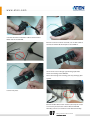
Installation Guide
GN0116 Guardian Over the NET™
www.aten.com
etc.
Ì Installation Process
7.
Ethernet: Used for browser connections to the
GN0116 from remote systems.
8.
Hardware Installation
Ports101, 102; 103,104; 105,106; and 107,108 are
digital output ports. The output voltage is 12VDC;
50mA. They can operate buzzers, warning lights
IP Setting
and other similar devices. They can also be
connected to an extension unit and used as
programmable power outlets.
Guardian Monitor Center Server
Installation
9.
Ports 1, 2 and 3, 4 are resistance type analog
input ports. The input resistance ranges from
2~205KΩ. The ports have 1024 levels of
Sensor Installation
resolution. With appropriate drivers, they can be
connected to thermistor or other
Configuration/Operation
resistance-output sensors (such as CDS sensors).
10. Ports 201,202 are digital input ports (dry contact).
They can be connected to On/Off-type output
Ì Product Front View
sensors (such as intrusion, access control, smoke,
and leakage sensors).
11. Ports 31, 32 are voltage-type analog input ports.
The input voltage ranges from 0~5VDC. The ports
have 1024 levels of resolution. With appropriate
drivers, they can be connected to sensors with
(Front View)
1.
Programmable AC Power Outlets
Ì Product Rear View
0~5 VDC output voltage, such as AC/DC voltage
sensors, current sensors and humidity sensors.
12. Reset Switch
13. Power Input
1.
AC Power Source Inlet
2.
Power Switch
3.
Circuit Breaker Switches
4.
485 Output: In a daisy chained installation this is
the chain out port of the parent station.
5.
485 Input: In a daisy chained installation this is
the chain in port of the child station.
6.
232C: Used for a serial connection (either from a
modem or a direct terminal connection from a
local console) for monitoring, software updating,
01
GN0116 Guardian Over the NET™
Installation Guide
Ì Hardware - Basic Installation
network cable into the RJ-45 port to connect the
GN0116 to the network.
> Power Connection
1.
Connect one end of the bundled Power Adapter to
the AC power source and the other end to the AC
power source inlet on the rear panel.
> RS-232 Connection
2.
Turn on the GN0116's power switch.
If you choose to use the RS-232 connection, connect
the RJ-45 connector on the bundled RS-232-to-RJ-45
cable to the port marked as 232C on the panel and the
RS-232 to the corresponding device (Computer COM
port or the MODEM port); as the demonstrator is using
a notebook computer, an additional ATEN UC232A was
used to convert the RS-232 signal to USB so it can be
passed to the notebook computer through the USB
interface.
Note: You may choose between an Ethernet or RS-232
connection. If you choose the Ethernet connection
then there is no need to connect the RS-232 port.
The GN0116 supports two types of network
connections – over the Ethernet or through RS-232.
RS-232 can be connected to a modem to support a
Dial-up connection. It can also be connected directly
to the computer COM Port so commands can be issued
through the RS-232 Port or for setting the Logic
Configuration and Proxy function.
> Ethernet Connection
If the Ethernet connection is used, connect the
02
GN0116 Guardian Over the NET™
Installation Guide
Ì IP Setting
Once the basic hardware installation is complete, an IP
address must be acquired/set for the GN0116 to allow
access.
Insert the bundled software CD and install the GN0116
software on the computer.
Ì Software Installation
The ATEN GN0116 offers three types of interface.
Choose the type suitable for your environment to use
for configuration and administration.
Once installation is complete, find the
Altusen\GN0116V1.6\FIrmwares\Monitor directory and
run the Monitor program.
y
Embedded Browser – Log in directly using the IP
address found by the Monitor program.
y
ssConsole – Bundled software that offers a
specially designed user interface.
y
External Guardian Monitor Center Server –
Installed on a server in the same network segment.
The administrator can manage the device through
a browser.
*Please see the User Manual for a description of each
user interface
> Guardian Monitor Center (GMC)
The demonstrator chose the Guardian Monitor Center
(GMC) software for this demonstration as it has more
features and a more user-friendly interface (available
as free download from the ATEN website).
The program will automatically scan all devices on the
Local Area Network (LAN) and list their IP addresses.
As the GMC uses a client-based structure, you need a
computer to act as the server for this software and the
computer must be on the same LAN segment as the
GN0116.
03
GN0116 Guardian Over the NET™
Installation Guide
After logging in and completing the device
configuration process (the GMC software will find all
GN0116 devices on the same network segment), the
notebook client can be used to view the status of all
GN0116 ports.
Guardian Monitor Center network diagram:
Ì Sensors Installation
After downloading and installing the Guardian
Monitor Center on the computer*, use the IP address
of the "installation computer" to open the browser
interface for GMC.
Once the demonstrator installs the software, s/he can
use the monitor connected to the server computer
(with GMC installed) and the client on the notebook to
open the browser as shown below.
*Please see the User Manual for the actual software
installation procedures
As mentioned in the Front View/ Rear View
introduction, the GN0116 mainly uses the four RJ-45
ports on the rear panel to connect to sensors or other
devices. Up to eight Digital Output (ports 101 ~ 108),
two Digital Inputs (ports 201 & 202) and six Analog
Inputs (including 4 resistor-types (ports 1 - 4) and two
voltage-types (31 & 32)) can be connected.
Note: The resistor-type and voltage-type ports must be
connected correctly or it will damage your system.
Guardian Monitor
Center Server
Client
04
GN0116 Guardian Over the NET™
Installation Guide
>Temperature Sensors
The GN0116 includes two sets of temperature sensors.
Each set contains two sensors.
Smoke Detector
Beeper
Reed Switch
As the sensors are connected to the GN01167 via a
RJ-45 port, a UTP cable with the RJ-45 connector is
needed to connect the sensors.
The included temperature sensors are of the Analog
Input type so they can be connected to ports 1 & 2 and
3 & 4.
To make the connection, strip the UTP wiring then
connect each wire to their respective sensor. Please
see the attached wire/PIN reference table for details.
>Smoke Detector / Beeper / Reed Switch
Apart from the bundled sensors, with the appropriate
cabling the GN0116 can also support a wide variety of
sensors available on the market.
For this demonstration, three sensor/alert devices
were chosen: Smoke Detector, Beeper and Reed
Switch.
Once the three sensor/alarm devices have been
connected to the UTP cable, insert the RJ-45 connector
to the 201/202 Digital Input ports.
05
GN0116 Guardian Over the NET™
Installation Guide
EA2110 - Current Detector
The EA2110 package includes one set of AC Current
Sensor + Cable. You can connect the clip-on sensor
device on one end of the cable to the power wire in
the power distribution box, or strip the AC power
cable and then clip it to any wire other than the
grounding one.
> Voltage Detector / Current Detector / Humidity
Sensor
Apart from the bundled sensors and devices sold on
the market, ATEN also offers three types of
easy-to-install sensors as options.
Here the demonstrator will demonstrate how to install
the EA2110 current detector and voltage detection
using the EA2310.
Stripping the clip-on sensor device.
EA2110/EA2210/EA2310 Sensor Boxes
Sensors are provided with a standard GN0116 package,
otherwise, ATEN offers the following models:
EA2110
1 x AC Current Sensor
Place the power wire on the clip-on sensor device.
and 1 x Humidity Sensor
EA2210
2 x AC Current Sensors
EA2310
1 x AC Current Sensor
and 1 x AC Voltage Sensor
Close the clip-on device to grip the wire.
06
GN0116 Guardian Over the NET™
Installation Guide
Connect the other end of the cable to the Terminal
Block slot on the EA2110.
Once the sensor has been secured, use an UTP cab le to
connect the EA2210's RJ-45 port to the GN0116.
Use the Port 31/32 voltage-type Analog Input Port
when connecting to the GN0116.
Note: Connecting to the wrong port may damage your
system.
Lock it into place.
Once the EA2110 has been installed, the clip-on sensor
can not only measure the current but the EA2110
humidity sensor can also be used to detect humidity.
07
GN0116 Guardian Over the NET™
Installation Guide
Use the Port 31/32 voltage-type Analog Input Port
when connecting to the GN0116.
Note: Connecting to the wrong port may damage your
system.
Humidity Sensor
EA2310 – Voltage Detector
The ATEN EA2310 Sensor Box is mainly used for
voltage detection. It provides one inlet and one outlet
port so installation is very simple.
Connect the power cable of the device to the monitor
(e.g. Server) to the power outlet on the EA2310.
Ì Configuration & Operation
Once the Sensors have been installed, the
pre-configured Guardian Monitor Server can be
connected through any client computer to make
changes.
Use the bundled power cable to connect the Inlet Port
to the AC power source.
Once the power source and device are both connected,
use a UTP cable to connec t the RJ-45 port on the
EA2310 to the GN0116.
08
GN0116 Guardian Over the NET™
Installation Guide
w w w. a t e n . c o m
Corporate Headquarters
ATEN International Co., Ltd.
3F, No.125, Sec. 2, Datung Rd. Sijhih City, Taipei 221, Taiwan
Phone: +886-2-8692-6789
Fax: +886-2-8692-6767
www.aten.com E-mail: [email protected]
.......................................................................................................................................
U.S.A. Subsidiaries:
Japan Subsidiary:
ATEN Technology Inc.
ATEN Japan Co., Ltd.
23 Hubble Drive, Irvine, CA 92618, U.S.A
Phone: +1-949-428-1111 Fax: +1-949-428-1100
www.aten-usa.com
E-mail: [email protected]
ATEN New Jersey Inc.
155 Pierce Street, Somerset, NJ 08873, U.S.A
Phone: +1-732-356-1703 Fax: +1-732-356-1639
www.aten-usa.com
E-mail: [email protected]
Belgium Subsidiary:
ATEN Infotech N.V.
Mijnwerkerslaan 34, 3550 Heusden-Zolder, Belgium
Phone: +32-11-531543
Fax: +32-11-531544
www.aten.be
E-mail: [email protected]
U.K. Subsidiary:
ATEN U.K. Limited
229 Berwick Avenue, Slough, SL1 4QT, U.K.
Phone: +44-1753-539-121 Fax: +44-1753-215-253
www.aten.co.uk
E-mail: [email protected]
© Copyright 2009 ATEN® International Co., Ltd.
8F Tatsumi Bldg. 16-6, Nishi-shinjuku 6-chome, Shinjuku-ku,
Tokyo 160-0023 Japan
Phone: +81-3-5323-7170
Fax: +81-3-5323-2181
www.atenjapan.jp
E-mail: [email protected]
Korea Subsidiary:
ATEN Advance Co., Ltd.
Eagle Town 3F #303, 278-20, Seongsu-dong 2-ga 3-Dong ,
Seongdong-gu, Seoul, Korea, 133-120
Phone: +82-2-467-6789
Fax: +82-2-467-9876
www.aten.co.kr
E-mail: [email protected]
China Subsidiary:
ATEN China Co., Ltd.
18/F,Tower A,Horizon International Tower,No.6,Zhichun
Road,Haidian District,Beijing,China 100088
Phone: +86-010-51294848 Fax: +86-86-010-82961318
www.aten.com.cn
E-mail: [email protected]
ATEN and the ATEN logo are trademarks of ATEN International Co., Ltd. All rights reserved.
All other trademarks are the property of their respective owners.