1
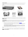
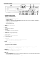
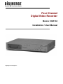
Four Channel
Digital Video Recorder
Models: DGR104
Installation / User Manual
Digimerge Technologies Inc.
Under the copyright laws, this documentation may not be copied, photocopied, reproduced, translated, or reduced to
any electronic medium or machine-readable form, in whole or part without the prior written consent of Digimerge
Technologies Inc., except in the manner described in the documentation.
© Copyright 2003
Digimerge Technologies Inc.
300 Alden Road
Markham, Ontario
L3R 4C1 CANADA
All rights reserved. Printed in Taiwan.
THIS DEVICE COMPLIES WITH PART 15 OF THE FCC RULES.
OPERATION IS SUBJECT TO THE FOLLOWING TWO CONDITIONS:
1. THIS DEVICE MAY NOT CAUSE HARMFULL INTERFERENCE, AND
2. THIS DEVICE MUST ACCEPT ANY INTERFERENCE RECEIVED,
INCLUDING INTERFERENCE THAT MAY CAUSE UNDESIRED
OPERATION.
NOTE: This equipment has been tested and found to comply with the limits for a Class B digital device, pursuant to part 15 of
the FCC Rules. These limits are designed to provide reasonable protection against harmful interference when the equipment
is operated in a commercial environment. This equipment generates, uses, and can radiate radio frequency energy and, if not
installed and used in accordance with the instruction manual, may cause harmful interference to radio communications.
However, there is no guarantee that interference will not occur in a particular installation.
Operation of this equipment in a residential area is likely to cause harmful interference in which case the user will be required
to correct the interference at one’s own expense.
CAUTION: CHANGES OR MODIFICATIONS NOT EXPRESSLY APPROVED BY THE PARTY RESPONSIBLE FOR
COMPLIANCE COULD VOID THE USER’S AUTHORITY TO OPERATE THE EQUIPMENT.
1
Table of Contents
Important Safety Instructions........................................................................................................................................................3
Introduction ..................................................................................................................................................................................4
Features .......................................................................................................................................................................................4
System Contents ..........................................................................................................................................................................5
Getting Started .............................................................................................................................................................................5
Front Panel Controls ....................................................................................................................................................................6
Back Panel ...................................................................................................................................................................................8
Accessing the Main Menu ............................................................................................................................................................9
Main Menu...............................................................................................................................................................................9
System Set Up.......................................................................................................................................................................10
Setting the Audio Input Channel..........................................................................................................................................10
Setting the Internal Audible Alarm Buzzer...........................................................................................................................10
Setting the External Audible Alarm device ..........................................................................................................................10
Setting the Alarm Duration ..................................................................................................................................................11
Setting the Dwell Time ........................................................................................................................................................11
Setting the Message Latch..................................................................................................................................................11
System Time/Date Set up......................................................................................................................................................11
Selecting the Date Display Format......................................................................................................................................11
Setting System Time & Date ...............................................................................................................................................11
Changing the System Password .........................................................................................................................................12
Clearing the Hard Drive Data ..............................................................................................................................................12
Resetting System to Factory Defaults .................................................................................................................................12
Remote Protocol Setup .......................................................................................................................................................12
Timer Recording Setup .......................................................................................................................................................13
Timer...................................................................................................................................................................................13
Record Settings...................................................................................................................................................................15
HDD Overwrite Setup:.........................................................................................................................................................15
Record IPS Setup: ..............................................................................................................................................................15
Record Quality Setup ..........................................................................................................................................................15
Alarm REC IPS setup..........................................................................................................................................................15
Alarm REC Quality setup ....................................................................................................................................................15
Motion Trigger Record ........................................................................................................................................................15
Camera Channel Setup.......................................................................................................................................................16
Motion Detection....................................................................................................................................................................18
Event Log Viewing ..............................................................................................................................................................20
Operation ...................................................................................................................................................................................21
On Screen Display (OSD) ...................................................................................................................................................21
Recording Methods .............................................................................................................................................................21
Viewing Options: .................................................................................................................................................................21
Individual Camera Select (1 - 4):.........................................................................................................................................21
Quad View Select:...............................................................................................................................................................21
Picture in Picture (PIP):.......................................................................................................................................................22
Zoom:..................................................................................................................................................................................22
Video Search ......................................................................................................................................................................22
Playing Back Video .............................................................................................................................................................22
Key Lock .............................................................................................................................................................................23
Troubleshooting .........................................................................................................................................................................24
Technical Specifications.............................................................................................................................................................25
Appendix 1: Installing the HDD ..................................................................................................................................................26
Appendix 2: Connection Diagram to Cameras and Monitor .......................................................................................................28
Appendix 3: Pin Configurations ..................................................................................................................................................29
Pin References for RS-232 / Alarm Block ...........................................................................................................................30
Appendix 4: Rack Mount Installation ..........................................................................................................................................31
Appendix 5: Recording Times (in Hours)....................................................................................................................................32
Appendix 6: RS232 Remote Protocol.........................................................................................................................................33
Appendix 7: Compatible HDD Brands ........................................................................................................................................34
Limited Warranty ........................................................................................................................................................................35
2
Important Safety Instructions
All the safety and operating instructions should be read before operating this equipment. The improper operation may cause
irreparable damage to the appliance.
Lift and place this equipment gently.
Do not expose this equipment to direct sunlight.
Do not use this equipment near water or in contact with water.
Do not spill liquid of any kind on the equipment.
Do not unplug the power connector before turning the power off correctly.
This equipment should be operated using only the power source from standard package.
Unauthorized repair or parts substitutions may result in fire, electric shock or other hazards.
Do not switch the Power On & Off within short period (within 3 seconds).
Do not attempt to service this equipment by yourself. Refer all servicing to qualified service personnel.
This installation should conform to all local codes.
CAUTION
RISK OF ELECTRIC SHOCK. DO NOT OPEN.
CAUTION:
!
TO REDUCE THE RISK OF ELECTRIC SHOCK, DO NOT REMOVE COVER (OR BACK). NO USERSERVICEABLE PARTS INSIDE. REFER SERVICING TO QUALIFIED SERVICE PERSONNEL.
3
Introduction
The DGR104 combines a 4 channel multiplexer with a Digital Video Recorder (DVR).
The DVR offers many advantages over traditional time lapse VCR’s, allowing you to quickly access and search for a specific
time segment or event which has been recorded. This high quality recorded video can be viewed at various playback speeds
as well as frame-by-frame with the Jog Button feature
To learn more about Digimerge products, please visit our website at www.digimerge.com.
Features
•
Wavelet Compression Format
•
4 Audio inputs and 2 outputs
•
Resolution: 704X564 - full screen, 352X282 - 4 channels, 224X188 9 - channels and 176X141- 16 channels
•
Independent main and call monitor outputs allow simultaneous or full screen viewing
•
Multi screen display mode
•
4 channel alarm input, alarm display and 1 alarm output
•
Video loss detection able to record 160 events on each channel
•
Power-loss memory feature (In case of power failure, set-up parameter will remain)
•
Supports 1 removable HDD, IDE type (up to a maximum of 120GB)
•
Display refresh rate up to 72 IPS (NTSC) and 50 IPS(PAL)
•
Record refresh rate up to 15 IPS (NTSC) and 12 IPS (PAL)
•
Quick multiple search by date/time, alarm or full list
•
Multiple speed playback
•
Security password protection
•
RS-232, RS-485 communication protocol
4
System Contents
The DGR104 box should include the items listed below. Please take a moment to verify that no items are missing from the
package.
DGR104 Digital Video Recorder
Installation / User Manual
Hard Disk Drive in Cartridge
(not included in all models)
2 Keys for
Hard Drive Cartridge
Power Adapter and Cord
NOTE: KEEP THE KEYS IN A SAFE PLACE. THEY ARE NECESSARY FOR INSTALLATION / REMOVAL OF THE HARD
DISK DRIVE.
Getting Started
If the purchased DVR model did not contain a hard disk drive, please refer to Appendix #1 for HDD installation
instructions.
1.
Connect video sources and monitor(s) following the configuration example shown in Appendix # 2.
2.
Connect the AC Power Cord to the Power Adapter and plug into an electrical outlet. A Red LED indicator light will be
ON to indicate that the DVR is in Standby mode.
3.
Press the Power button. The POWER LED will turn from red to orange, and other red LED indicators will turn ON.
Note: the system takes approximately 5 to 15 seconds to power up. During the power-up, you will see the following
messages: “HDD Detecting”, followed by “Master HDD Connected”.
Once connected, the POWER LED will change to green, and the red indicator lights will be ON next to the Alarm and Timer
buttons.
NOTE: IF YOU GET THE MESSAGE “HDD NOT FOUND”, PLEASE SEE APPENDIX #1 AS THE HDD IS LIKELY NOT
INSTALLED CORRECTLY.
5
Front Panel Controls
1
17
3
4
5
2
6
7
8
17
15
13
10 14
9
12
11
1.
REMOVABLE HDD CARTRIDGE
Please refer to page.19 Appendix #1.
2.
LED LIGHT
The LED Light is ON under following condition.
•
HDD Full: HDD is full
•
ALARM: If you want to turn off the ALARM LED light, please refer to page 13 and set the Camera / ALARM item as
OFF (all of the cameras should be set as OFF.)
•
TIMER: When Timer is set as Enabled
•
PLAY: On Play mode
•
REC: On Recording mode
3.
MENU
Press MENU to enter main menu.
4.
ENTER
Press ENTER for confirmation.
5.
SEARCH
Press SEARCH for searching recording video.
6.
ZOOM
Press ZOOM to enlarge the picture display.
7.
Picture in Picture
Press PIP button for Picture in Picture screen.
8.
4 channels display mode
9.
STOP / Down
•
STOP: Under DMR Record / Play mode, it can stop the moment action.
•
DOWN: Under setup mode, it works as Down button.
10. PLAY
Press PLAY to playback recorded video.
11. POWER
Press Power to turn ON / OFF the DMR.
12. FF / Right
•
FF: It can play video forward at high speed, and press FF again to adjust speed from 1, 2, 4, 8, 16, 32 times.
•
Right: Under setup mode, it can work as Right button.
13. PAUSE / Up
•
Pause: Under DMR play mode, it can pause the action.
•
UP: Under setup mode, it works as Up button.
14. REW / Left
•
REW: Under DMR play mode, it can play video backward at different speeds. (Press REW again to adjust speed as
1, 2, 4, 8, 16, 32 times)
•
Left: Under setup mode, it works as Left button.
6
15. REC
•
Press REC to start recording.
16. SLOW
•
To slow down speed of play mode.
17. CAMERA SELECT (1-4)
•
Press the Camera Select (1-4) to select specified camera
7
Back Panel
1.
POWER INPUT
Connects to the Power cord.
2.
EXTERNAL I/O
Connects to a PC for Remote Control via RS-232 or to an Alarm Block. (see appendix 6 for more info)
3.
75/HI
When using the LOOP function, allows for HI impedance or 75ohms.
4.
VIDEO INPUT (1-4)
Connects to a video source i.e (camera).
5.
LOOP
Allows connection to other video devices
6.
AUDIO INPUTS (1-4)
Connects to an audio source for recording purposes (i.e. microphone)
7.
AUDIO OUTPUTS (R/L)
Connects to a speaker (or a monitor with audio speaker)
8.
MONITOR
Connects to main monitor
9.
CALL
Connects to the CALL monitor for real time sequencing.
8
Accessing the Main Menu
The Menu allows you to configure your DVR settings and program various recording options.
Follow these steps in order to access the Menu:
Press the MENU button. The password screen will appear:
Password: 0000
The default Password is 0000.
To change the number of the Password, use the ◄ / ► buttons to scroll left and right between numbers, and use the ▲ / ▼
buttons to change the value of the number that is flashing.
Press the ENTER button once the correct Password is entered. The menu options screen will appear.
NOTE: If you get a message “Password Error”, you have entered an incorrect password.
Main Menu
When the correct password is entered, the main menu options will be displayed.
There are 5 options available in the Main Menu:
Timer:
Record:
Camera:
System:
Event:
Scheduling Recording
Record mode set-up
Camera channel set-up
System Setup (Sets the date, chooses an HDD overwrite setting, changes
password, resets system settings, or clears the HDD)
Event List - Allows you to view video from a list of recorded events
►
(Menu)
Timer
Record
Camera
System
Event
Navigating the Menu:
▲ / ▼:
◄ / ►:
Scroll up and down through menu options; change values when an option is selected and is blinking
Scroll sideways within a menu option that has been selected
ENTER:
MENU:
Selects a submenu / an option in a submenu for browsing / modification
Completes modification of a menu option; exits a menu
NOTE: The Menu setup will timeout after 1 minute of no key presses.
9
System Set Up
The system menu is used to configure the system level options of the DGR104…
To access the System features, press MENU followed by the 4-digit password. Use the ▲ / ▼ to scroll to the ‘System’ option
and press ENTER.
(SYSTEM)
Audio Input:
Int Audible Alarm:
Ext Audible Alarm:
Alarm Duration:
Dwell Time:
Message Latch:
Title Display:
Time Display:
2003-JAN-02 (THU)
New Password:
Clear HDD:
System Reset:
Remote Mode:
Baud Rate:
Remote ID:
1
ON
ON
10 SEC
02 SEC
NO
ON
Y/M/D
17:37:09
XXXX
NO
NO
RS-232
9600
000
Using the ▲ / ▼ buttons, scroll to the desired option and press ENTER to select it.
Setting the Audio Input Channel
This Feature is used to select the audio channel to record. To set this Audio Input Channel:
1.
2.
3.
4.
On the System screen, press ▲ / ▼ to select Audio Input, then press ENTER.
Press ▲ / ▼ to select the desired time audio channel (1-4)
Press MENU to confirm your change.
Press ▲ / ▼ to move to another field on the System screen or press MENU to exit.
Setting the Internal Audible Alarm Buzzer
To enable or disable the internal audible alarm buzzer:
1.
2.
3.
4.
On the System screen, press ▲ / ▼ to select Internal audible alarm buzzer, then press ENTER.
Press ▲ / ▼ to enable or disable the internal audible alarm buzzer. Options are:
ON = Buzzer is on. When the DVR detects an alarm, the system sounds the internal buzzer to alert the user.
OFF = Buzzer is off.
Press MENU to confirm your change.
Press ▲ / ▼ to move to another field on the System screen or press MENU to exit.
Setting the External Audible Alarm device
To enable or disable the External Audible Alarm Device:
1.
2.
3.
4.
On the System screen, press ▲ / ▼ to select External Audible Alarm Device, then press ENTER.
Press ▲ / ▼ to enable or disable the External Audible Alarm Device. Options are:
ON = External Device is on. When the DVR detects an alarm, the system triggers the external audible alarm.
OFF = External Device is Off
Press MENU to confirm your change.
Press ▲ / ▼ to move to another field on the System screen or press MENU to exit.
10
Setting the Alarm Duration
To set the duration of the Alarm:
1.
2.
3.
4.
On the System screen, press ▲ / ▼ to select Alarm Duration, then press ENTER.
Press ▲ / ▼ to select the desired time (10s, 15s, 20, 30, 1min, 2min, 3min, 5min, 10min, 15min, 30min, always)
Press MENU to confirm your change.
Press ▲ / ▼ to move to another field on the System screen or press MENU to exit.
Setting the Dwell Time
This timer is used to select the amount of time (between 1-10s) a channel appears on the call monitor before sequencing to
the next channel. To Set the Dwell Time:
1.
2.
3.
4.
On the System screen, press ▲ / ▼ to select Dwell Time, then press ENTER.
Press ▲ / ▼ to select the desired time (1-10s)
Press MENU to confirm your change.
Press ▲ / ▼ to move to another field on the System screen or press MENU to exit.
Setting the Message Latch
This feature determines if the On Screen messages will remain on the screen or disappear after 10s. To set the Message
Latch:
1.
2.
3.
4.
On the System screen, press ▲ / ▼ to select Message Latch, then press ENTER.
Press ▲ / ▼ to enable or disable the Message Latch feature. Options are:
NO = Screen messages will disappear after a 10 sec. (this is the default setting)
YES = On Screen messages will remain on the screen for the duration of the event.
Press MENU to confirm your change.
Press ▲ / ▼ to move to another field on the System screen or press MENU to exit.
System Time/Date Set up
Selecting the Date Display Format
1.
2.
3.
4.
On the System screen, press ▲ / ▼ to select Date Display, then press ENTER.
Press ▲ / ▼ to choose a display format. Options are:
Y-M-D = Year - Month - Day
M-D-Y = Month - Day - Year
D-M-Y = Day – Month - Year
Off = The date and time will not show on the screen.
Press MENU to confirm your change.
Press ▲ / ▼ to move to another field on the System screen or press MENU to exit this screen and confirm the
current operation.
Setting System Time & Date
1.
2.
3.
4.
On the System screen, press ▲ / ▼ to select System Time & Date, then press ENTER.
Press ▲ / ▼ to choose a number, then press ◄ / ►to move to the next digit:
2003-Jan-01 (Mon) 22:38:29
Press MENU to confirm your change.
Press ▲ / ▼ to move to another field on the System screen or press MENU to exit this screen and confirm the
current operation.
11
Changing the System Password
1.
2.
3.
4.
5.
On the System screen, press ▲ / ▼ to select New Password, then press ENTER.
Press ▲ / ▼ to choose a number, then press ◄ / ► to move to the next digit:
Press MENU to confirm your change.
Press ▲ / ▼ move to another field on the System screen or press MENU to exit this screen and confirm the current
operation.
If you have completed all your system configuration changes, press MENU again to exit and close menu setup.
Clearing the Hard Drive Data
This option will erase all data from the hard drive.
Ensure that there are no important recordings on the disk before using this option.
1.
2.
3.
4.
5.
6.
On the System screen, press ▲ / ▼ to select Clear HDD, and then press ENTER.
Press ▲ / ▼ to choose YES to clear the HDD or NO to leave as is.
When you choose “Yes” on this option and press ENTER, the DVR will prompt:
Press ►to confirm clearing, or ◄ to cancel.
Press MENU to confirm your change.
Press ▲ / ▼ to move to another field on the System screen or press MENU to exit this
screen and confirm the current operation.
All Data in HDD
Will Be Cleared
Are you sure?
(◄ : No ► : Yes )
NOTE: Clearing the data from the Hard Drive results in permanent, irreversible loss of all video and related data currently
stored on the Hard Drive.
Resetting System to Factory Defaults
Using the System Reset option will set all options back to factory default settings. Use the steps below to perform this option.
1.
2.
3.
4.
On the System screen, press ▲ / ▼ to select System Reset, and then press ENTER.
Press ▲ / ▼ to choose:
Yes = Confirm the system reset and load the default settings.
No = Do not reset the system at this time.
Press MENU to exit this screen and confirm the current operation.
If you have completed all your system configuration changes, press MENU again to exit and close menu setup.
NOTE: This will not affect the time and date settings.
Remote Protocol Setup
This feature is used to set the basic RS-232/RS-485 protocols to control the DVR remotely from a PC.
Pressing ENTER after scrolling to the Remote option will bring up the following menu options:
Remote mode:
Selects whether to use an RS-232 or RS-485 interface.
Baud rate:
Selects the baud rate (bps) to be used for the connection.
The available settings are: 115200, 57600, 19200, 9600, 3600, 2400, 1200.
ID:
Selects a numerical number representing the DVR being controlled if multiple
units are being used.
The available setting are: 000 – 255
12
(Menu)
Timer
Record
Alarm
►Remote
System
Event
The remote connection on the DVR uses 8 data bits, 1 start bit, and 1 stop bit, no Parity.
Below is an example of the data stream with the control codes shown.
ACT – OxFF
OxCO
ID
FUNCTION
STOP – Ox7F
Please refer to Appendix 3 for information on the Pin connections and command protocols that would be used in this
application.
Timer Recording Setup
On the Main menu, selecting the Timer option will allow you to set daily schedules in which
you would like the DVR to automatically record.
Pressing ENTER after scrolling to the Timer option will bring up the following menu options:
Timer
(Timer)
Day
Start End
Daily
01:00 02:00
SUN
12:00 13:00
MON
08:00 09:00
MO~FR 00:00 01:00
SA~SU
20:00 21:00
JAN-01
15:00 16:00
Timer Enable:
No
IPS
Off
Off
Off
Off
Off
Off
1.
Press ▲ / ▼ to select the day(s) to record on, the available options are…
Daily:
Everyday
SUN:
Sunday
MON:
Monday
TUE:
Tuesday
WED:
Wednesday
THU:
Thursday
FRI:
Friday
SAT:
Saturday
MO-FR: Monday to Friday
SA-SU:
Saturday & Sunday
JAN-01: Special Date
OFF:
Not activated
2.
Use the ◄ / ► scroll keys to move to START record time 00:00 (HH:MM)
Press ▲ / ▼ to set the start time
3.
Press ◄ / ► move to END record time 00:00 (HH:MM)
Press ▲ / ▼ to change END record Time numerical digit
4.
Press ◄ / ► move to QUALITY
Press▲ / ▼ to choose options of
BEST, HIGH, NORMAL, BASIC
5.
Press ◄ / ► move to Record IPS (Images Per Second)
Press▲ / ▼ to choose one of the following options
NTSC: 15A, 15, 8, 4, 2, 1
PAL: 12A, 12, 6, 3, 2, 1
6.
Press MENU to confirm current operation, and enter to next Timer Record setup.
13
(Menu)
►Timer
Record
Alarm
Remote
System
Event
7.
Press ◄ / ► move location to Timer Enable Yes or No setup
YES : To confirm Timer Enable Scheduling Timer Record feature
NO : To confirm no Timer Enable No Scheduling Timer Record feature
8.
Press MENU to exit and confirm current operation.
9.
Press MENU again to exit and close TIMER setup mode.
NOTE: WHEN THE TIMER IS SET, THE REC LED INDICATOR WILL BE ON. ALTHOUGH THE LIGHT MAY BE ON, THE
SYSTEM IS NOT NECESSARILY RECORDING SINCE IT WILL ONLY RECORD DURING ITS SCHEDULED TIME.
14
Record Settings
On the Main menu, selecting the Record option will allow you to set the quality and speed of
recordings.
Pressing ENTER after scrolling to the Record option will bring up the following menu
options:
(RECORD)
HDD Overwrite: NO
Record IPS: 25A
Record Quality: Normal
Alarm Rec IPS: 25A
Alarm Rec Quality: Normal
Motion Trigger Record: ON
HDD Overwrite Setup:
1.
2.
3.
4.
Press ENTER to confirm HDD OVERWRITE setup.
Press ▲ / ▼ to choose HDD OVERWRITE.
NO: When HDD full will stop recording
YES: When HDD full will overwrite the HDD recording
Press MENU to exit and confirm current operation.
Press MENU again to exit and close HDD OVERWRITE setup mode.
Record IPS Setup:
1.
2.
3.
4.
Press ENTER to confirm RECORD IPS setup.
Press ▲ / ▼ to choose IPS record speed. Note that ‘15A’ indicates 15 ips with audio.
NTSC: 25A, 15, 8, 4, 2, 1
PAL: 18A, 12, 6, 3, 2, 1
Press MENU to exit and confirm current operation.
Press MENU again to exit and close RECORD IPS setup mode.
Record Quality Setup
1.
2.
Press ENTER to confirm Record Quality setup.
Press▲ / ▼ to choose Record Quality level.
BEST, HIGH, NORMAL, BASIC
3. Press MENU to exit and confirm current operation.
4. Press MENU again to exit and close RECORD QUALITY setup mode.
Alarm REC IPS setup
1.
2.
3.
4.
Press ENTER to confirm ALARM REC IPS setup.
Press ▲ / ▼ to choose ALARM REC IPS record speed.
NTSC: 15A, 15, 8, 4, 2, 1
PAL: 12A, 12, 6, 3, 2, 1
Press MENU to exit and confirm current operation.
Press MENU again to exit and close ALARM REC IPS setup mode.
Alarm REC Quality setup
1.
2.
3.
4.
Press ENTER to confirm ALARM REC QUALITY setup.
Press▲ / ▼ to choose ALARM REC QUALITY level.
BEST, HIGH, NORMAL, BASIC
Press MENU to exit and confirm current operation.
Press MENU again to exit and close ALARM REC QUALITY setup mode.
Motion Trigger Record
1.
2.
Press ENTER to confirm MOTION TRIGGER RECORD setup.
Press▲ / ▼ to toggle the option between ON and OFF.
15
►
(Menu)
Timer
Record
Alarm
Remote
System
Event
Camera Channel Setup
To access the Camera option, press MENU followed by the 4-digit password. Use the ▲ / ▼ to scroll to the Camera option
and press ENTER.
TITLE
DWELL
ALARM
RECORD
---01
ON
5
5
5
LOW
EVENT
---02
ON
5
5
5
LOW
EVENT
---03
ON
5
5
5
LOW
EVENT
---04
ON
5
5
5
LOW
EVENT
The options available in this section are as follows…
Title
This feature is used to assign a 6-character title to each camera input.
1. Press ▲ / ▼ to select the desired time camera channel (1-4), then press ENTER.
2. Press ▲ / ▼ to select the desired character and ◄ / ►to move to the next character
3. Press MENU to confirm and exit the Title setting.
4. Press MENU again to exit the Camera Setup Option
Dwell
This feature is used to enable or disable the dwell feature for each camera when viewing using the call monitor output.
1. Press ▲ / ▼ to select the desired time camera channel (1-4), then press ENTER.
2. Press ◄ / ► to select the Dwell feature on the screen.
3. Press MENU to confirm and exit the dwell setting.
4. Press MENU again to exit the Camera Setup Option
Brightness / Contrast / Color
This feature is used to adjust the video settings on each channel.
1.
2.
3.
4.
5.
Press ▲ / ▼ to select the desired time camera channel (1-4), then press ENTER.
Press ◄ / ► to select the Brightness, Contrast, or Color feature on the screen.
Press ▲ / ▼ to select 0~9 on the screen.
Press MENU to confirm and exit the Brightness, Contrast, or Color control feature
Press MENU again to exit the Camera Setup Option
Alarm Polarity
This feature is used to select the alarm polarity as LOW / OFF / HIGH.
1. Press ▲ / ▼ to select the desired time camera channel (1-4), then press ENTER.
2. Press ◄ / ► to select the Alarm Polarity feature on the screen.
3. Press ▲ / ▼ to select LOW / OFF / HIGH on the screen.
4. Press MENU to confirm and exit the Alarm Polarity feature
5. Press MENU again to exit the Camera Setup Option
16
Record Method
This feature is used to select the DVR record method as either EVENT / NORMAL / OFF.
1. Press ▲ / ▼ to select the desired time camera channel (1-4), then press ENTER.
2. Press ◄ / ► to select the Record Method feature on the screen.
3. Press ▲ / ▼ to select EVENT/ NORMAL/ OFF on the screen.
EVENT:
when the alarm input is triggered, the DVR will increase the recording time to that channel.
i.e. the normal record sequence for cameras is camera 1, camera 2, camera 3 etc… In Event mode, when an
alarm in triggered from channel 1, the DVR will record using the following sequence…., Camera 1, Camera 2,
Camera 1, Camera 3, Camera 1, Camera 4 etc….
NORMAL: When an External Audible Alarm is triggered, the DVR will record normally as set up.
OFF:
An Alarm Trigger will not cause the DVR to start recording
4. Press MENU to confirm and exit the Record Method feature
5. Press MENU again to exit the Camera Setup Option
17
Motion Detection
The Motion Detect feature provides a visual indication on the monitor when movement is detected in the picture. Note that this
does not trigger recording.
Press MENU to enter the menu set up, then ▼ to CAMERA setup.
Press ENTER twice to enter the Motion Detection Setup.
Each screen displays the current camera picture overlaid with the motion targets (as Figure 1). Pressing the ◄ / ►, ▲ / ▼
buttons will toggle the motion detection between ON or OFF.
The targets on each motion setup can be turned to ON or OFF individually by row. To set up targets, using the following front
panel buttons:
1. Press ENTER to confirm the channel
2. Press ENTER to enter motion mode
3. ▲ moves the target cursor up one row at a time.
4. ▼ moves the target cursor down one row at a time.
5. ◄ moves the target cursor left one column at a time.
6. ► moves the target cursor right one column at a time.
7. Press ENTER to turn the target cursor ON
Press ENTER again to turn the target cursor OFF
8. Camera Select (1-15) toggles the corresponding target on the cursor line ON or OFF. (see Figure 1.1) There are
only 15 targets in a row, therefore; only Camera Selected (1-15) can be operated.
9. Zoom: turns all targets in the current row ON or OFF. (Figure 1-2)
10. PIP: turns all targets on the screen ON or OFF. (Figure 1-3)
Press SLOW button to setup the Sensitivity list up to 255
1. Press REC button to setup the Sensitivity list down to 000
2. Sensitivity value is related to motion and brightness change.
3. Low value (as 001) means higher sensitivity on motion and brightness change.
4. High value (as 255) means lower sensitivity on motion and brightness change.
User can choose the suitable sensitivity value in different locations. The default value is set on 32.
Figure 1 MOTION DETECTION SETUP
1
2
3
4
5
6
7
8
9
10
11
12
13
14
15
032
--
--
--
--
--
--
--
--
--
18
--
--
--
--
--
--
Figure 1-1 MOTION DETECTION SETUP – 1~4
1
2
3
4
5
6
7
8
9
10
11
12
13
14
15
032
--
--
--
--
--
--
--
--
--
--
--
--
--
--
--
Figure 1-2 MOTION DETECTION SETUP – LINE
1
2
3
4
5
6
7
8
9
10
11
12
13
14
15
032
--
--
--
--
--
--
--
--
--
--
--
--
--
--
--
Figure 1-3 MOTION DETECTION SETUP – ALL
1
2
3
4
5
6
7
8
9
10
11
12
13
14
15
032
--
--
--
--
--
--
--
--
--
--
19
--
--
--
--
--
Event Log Viewing
To access the Event Log Viewing option, press MENU followed by the 4-digit password. Use the ▲ / ▼ to scroll to the Event
option and press ENTER to view the list of logged events.
Use the ▲ / ▼ to scroll through the events on the display and ◄ / ► to go to the next page. To view
the video associated with an event, scroll to the event and press ENTER.
The following is a list of events that can be displayed on the DGR104.
M-HDD WARNING:
M-HDD LOSS:
M-HDD ERROR:
S-HDD WARNING:
S-HDD LOSS:
S-HDD ERROR:
HDD FULL:
SYSTEM ERROR:
------02 VLOSS:
------03 ALARM:
POWER RESTORE:
Master HDD might be failed
Master HDD does not exist. User can use other HDD.
Master HDD may contain error.
Slave HDD may have failed.
Slave HDD does not exist. User can use other HDD
Slave HDD may contain error.
HDD is full.
System may have failed.
Channel: 2 Video Loss
Channel: 3 External I/O Alarm triggered.
Power restore.
20
(Menu)
Timer
Record
Alarm
Remote
System
► Event
Operation
On Screen Display (OSD)
The DGR100/101 will display all current status on the OSD.
2002 – JAN –01 01:02:03
Here is an example of the display.
E
32GB
The following status will be shown:
Time and Date – The current time and date will be shown on the first line.
Record Type – The current recording method will be shown:
M= Manual, T= Timer, A= Alarm, E= External Trigger
Record Status – An
icon will be displayed when the unit is currently recording
HDD Status – This will display either the remaining HDD capacity in GB or OW to indicate
that it is set to Overwrite.
Video Loss - Screen will display
if the video input is not connected properly.
Recording Methods
The DGR104 offers a variety of flexible recording modes. The unit can be set up to record continually, following a schedule, or
by record events. In addition, the recording speed and resolution is also configurable (these options are configurable through
the system menu). Under the recording status, if power is stopped accidentally, recorded video will still be stored in the HDD
and will be available when the power is restored, and the original recording setup will remain.
When recording, the top line of the display will show the date, time, and the amount of available HDD memory (in GB).
In the example below, the letter “A” represents the alarm trigger and the letters “OW” represents HDD over write.
2002 – JAN –01 01:02:03
A●OW
There are 3 record modes for DGR104: Alarm Record, Timer Record, and Manual Record.
1.
2.
3.
4.
Alarm Record
The display will indicate a recording triggered by an Alarm using the letter “A”.
Timer Record
The display will indicate a scheduled recording using the letter “T”.
Manual Record
The display will indicate a manual recording (by pressing the REC button) using the letter “M”.
Motion Trigger Record
Recording will be triggered by motion sensing and is indicated with the letter ‘D’.
Viewing Options:
Individual Camera Select (1 - 4):
Press Camera Select (1 - 4) button to select the desired camera to display in full screen mode.
Quad View Select:
This button is used to select the ideal viewing configuration.
1.
Press the
button to toggle from an individual camera to a quad display.
21
Picture in Picture (PIP):
This button is used to configure the monitor so a full screen is displayed in the background with a 1/16th size screen insert.
1.
2.
3.
Press the
button to display the PIP mode.
Press SELECT then ◄ / ► button to move the insert screen.
Press MENU to exit
Zoom:
Feature is used to enlarge the display (2X) the size of the main picture. The screen will now display the “zoomed” picture
as the main picture with a small window inserted containing a moveable 1/4 view size of the appointed camera.
1.
2.
3.
4.
Select the desired camera by pressing Camera Select (1-4).
Press the Zoom button to zoom the image on the display.
Press the Zoom button again to move the zoom pointer.
Press MENU to exit
Video Search
The DVR allows you to easily find sections of recorded video using the Search feature.
Press the SEARCH button and you will see the following options:
Last Record: Plays the last recorded piece of video.
Full List:
Shows a listing of all recorded video on the HDD, sorted by time.
Alarm List:
Shows a listing of all recorded video triggered by an Alarm.
►Last Record
Full List
Alarm List
Time Search
Time Search: Finds video recorded on a specific date that is entered.
An example of a Full List search is shown on the left.
►M 2002-JAN-01 01:02:03
M 2002-JAN-01 01:02:03
A 2002-JAN-01 01:02:03
T 2002-JAN-01 01:02:03
E 2002-JAN-01 01:02:03
M 2002-JAN-01 01:02:03
◄: Page Up ►: Page Down
Note that the date and time appear, along with the letter
representing the method of recording that took place.
Simply press ENTER to view a selected piece of video on
the list. The DVR will play that video, followed by the next
video in chronological order, until it hits the End of the list.
You can stop the video at any time by pressing the STOP
button.
Playing Back Video
Pressing PLAY while in Normal operation will play back the most recently recorded video clip. The controls below will allow
you further controls over the playback whether in this mode or when viewing video from the Search mode.
Fast forward -
Press PLAY on the front panel, then press FF/► to open the fast forward search screen.
Press FF/► once to increase the speed to 2X, twice to increase the speed to 4X, and so on. The maximum
fast forward speed is 32X.
Fast Reverse -
Press PLAY on the front panel, then press REW/◄ to open the fast reverse search screen.
Press REW/◄ once to increase the reverse speed to 2X, twice to increase the reverse speed to 4X, and so
on. The maximum fast rewind speed is 32X.
Slow forward -
Press PLAY on the front panel, then press SLOW for slow play. Press FF/► to play images at slow speed
(1/2X). Press FF/► again to slow the speed to 1/4X. Continue to press FF/► to slow down the speed. The
minimum slow speed is 1/32X.
22
Slow reverse
Press PLAY on the front panel, then press SLOW for slow forward. Press REW/◄ to play images slowly
forward (1/2X). Press REW/◄ again to slow the speed to 1/4X. Continue to press REW/◄ to slow down the
speed. The minimum slow forward speed is 1/32X.
Image Jog
Press PLAY on the front panel, then press PAUSE to lock the current image on the screen.
Press FF/► to select single image play. Each time you press FF/► the next image will display. Continuing
to press FF/► will result in forward image-by-image playback.
Pressing REW/◄ will result in reverse image by image playback.
Pause
Press PLAY on the front panel, and then press PAUSE/▲ to lock the current image on the screen.
Stop
Press STOP on the front panel whenever you want to return the DVR to live monitoring mode.
Key Lock
For added security, you can Lock the buttons on your DGR104. Locking disables the functionality of the buttons and
prevents accidental key presses from altering the operation of the DGR104.
To enable the Key Lock feature, press and hold the ENTER and MENU at the same time.
To disable the Key Lock feature when it is locked, press and the ENTER and MENU at the same time.
23
Troubleshooting
PROBLEM
SOLUTION
HDD not found
Need to insert HDD
Make sure that the HDD Cartridge is locked, then
press any key to continue
No Power
Check the power source cord connections
Check that there is power at the outlet
Buttons aren’t working when pressed
Check if the system is in Key Lock mode
Press MENU and ENTER at the same time to
escape the Key Lock mode
No recorded video
Check that the HDD has been installed correctly
Timer / Alarm recording isn’t working
Check that Timer / Alarm Enable is set to YES
No video
Check camera’s video cables and connections
Check monitor’s video cables and connections
Make sure that the camera is receiving power
24
Technical Specifications
Video format
NTSC/EIA or PAL/CCIR
HDD storage
IDE type, UTMA 66 above, 2 removable HDD’s supported
Record mode
Manual / Alarm / Timer
Camera input signal
Composite video signal 1 Vp-p 75Ω BNC, 4 Channels
Camera loop back
Composite video signal 1 Vp-p 75Ω BNC, 4 Channels
Main monitor output
Composite video signal 1 Vp-p 75Ω BNC
Call monitor output
Composite video signal 1 Vp-p 75Ω BNC
Audio input/ output
4 audio inputs, (RCA) and 2 audio outputs, (RCA)
Motion detect area
15 X 12 Targets per camera (NTSC)/ 15*14 targets per camera (PAL)
Motion detect sensitivity
256 Levels
Video loss detection
Yes
Refresh rate
72 IPS for NTSC / 100 IPS for PAL
Recording rate
15 IPS for NTSC / 12 IPS for PAL
Dwell time
Programmable (1 - 10 Sec)
Picture in picture
Yes (Moveable)
Key lock
Yes
Picture zoom
2X (Moveable)
Camera title
6 Characters
Video adjustable
Color / Contrast / Brightness Adjustable
Alarm input / output
Input: TTL input, Hi (5V), Low (GND)
Remote control
RS-232 or RS-485
Time display format
YY/NN/DD, DD/MM/YY, MM/DD/YY, OFF
Output: COM,/N.O/N.C
Power source
AC 100-240V +/- 10% switching adaptor
Power consumption
<45W
Operation temperature
10 - 40 degrees C
RS - 232c / RS-485
115200, 57600, 19200, 9600, 4800, 3600, 2400, 1200 bps
Dimension (mm)
432 (W) x 110 (H) x 325 (D)
Net weight
5.7 Kgs
25
Appendix 1: Installing the HDD
NOTE: The HDD has the same purpose in a DGR104 as a videocassette does in a VCR. However, installing the HDD is a bit
more complicated. Please follow the next steps carefully in order to ensure proper installation.
The compartment (with the handle) located on the front panel of the DGR104 is the removable Cartridge Casing where the
HDD is inserted. The various parts of the Cartridge Casing are labeled for your reference.
Cartridge Casing
1.
2.
3.
Keyhole
LED indicator lights (Power indicator & HDD Access indicator)
Handle
Step 1: Remove the Cartridge Casing from the DGR104
Lift the Handle and pull towards you. The Cartridge Casing will slide out of the DGR104.
NOTE: The Cartridge must be unlocked to remove it, (please see step 8 for more information on locking and unlocking the
removable HDD cartridge).
Step 2: Remove the Cover from the Cartridge Casing
Step 3: Unclip the release latch with the word “OPEN,” printed beside it by gently pushing on the latch.
Step 4: Slide the cover off the Cartridge Casing.
Step 5: Insert the HDD into the Cartridge Casing
Take the Hard Disk Drive and connect the two cables from the back of the Cartridge Casing to the HDD.
The cables should be pushed in firmly, but not forcibly.
Note:
When using more than 1 HDD, configure the jumpers on the HDD so one is selected ad the Master, and the other as
Slave, OR configure the jumpers on the HD for CS (Cable Select), and the DVR 104 will do this automatically.
The jumper settings for Master / Slave / Cable Select are usually labeled on the top side of the HDD and the location
of the jumpers can usually be found beside the cable connector on the HDD
26
Step 6: Secure the HDD in the cartridge casing.
Position the HDD into place and secure it using the six screws supplied.
Step 7: Slide the top Cover over the Cartridge Casing
Slide the Cover forward over the Cartridge Case. Ensure it is secured in place over the release latch.
Reinsert the Cartridge Casing into the DGR104
Step 8: Lock the Cartridge
To Lock the cabinet, turn the key clockwise to Position A.
A
(locked)
B
(unlocked)
To unlock the cabinet, turn the key counter-clockwise to Position B.
NOTE: The DGR104 will not function if the key is not in the locked position.
27
Appendix 2: Connection Diagram to Cameras and Monitor
28
Appendix 3: Pin Configurations
9 pin Comm Port
25 Pin Comm Port
29
Pin References for RS-232 / Alarm Block
PIN 1. GND
GROUND
PIN 18. ALARM INPUT 1
Used to connect an alarm sensor between ALARM INPUT 1 (PIN 18) and GND (PIN 1) to trigger an alarm on
Camera 1, which can activate the internal audible alarm and start recording.
PIN 5. ALARM INPUT 2
Used to connect an alarm sensor between ALARM INPUT 2 (PIN 5) and GND (PIN 1) to trigger an alarm on Camera
5 which can activate the internal audible alarm and start recording.
PIN 17. ALARM INPUT 3
Used to connect an alarm sensor between ALARM INPUT 3 (PIN 17) and GND (PIN 1) to trigger an alarm on
Camera 3 which can activate the internal audible alarm and start recording.
PIN 4. ALARM INPUT 4
Used to connect an alarm sensor between ALARM INPUT 4 (PIN 4) and GND (PIN 1) to trigger an alarm on Camera
4 which can activate the internal audible alarm and start recording.
PIN 11. RS232-TX
The DVR can be controlled remotely by an external device or control system, such as a control keyboard, using RS232 serial communications signals.
PIN 23. RS232-RX
The DVR can be controlled remotely by an external device or control system, such as a control keyboard, using RS232 serial communications signals.
PIN 12. RS485-A
The DVR can be controlled remotely by an external device or control system, such as a control keyboard, using
RS485 serial communications signals.
PIN 24. RS485-B
The DVR can be controlled remotely by an external device or control system, such as a control keyboard, using
RS485 serial communications signals.
PIN 13. EXTERNAL ALARM NO
Under normal operation COM disconnect with NO. But when Alarm triggered, COM connect with NO.
PIN 25. EXTERNAL ALARM COM
Under normal operation COM disconnect with NO. But when alarm triggered, COM connect with NO.
30
Appendix 4: Rack Mount Installation
Screws and brackets for rack mounting applications can be purchased as an optional accessory.
Front Angle with Rack Mount
Side View with Rack Mount
For more information about the rack mount & other accessories through Digimerge, please visit:
www.digimerge.com.
31
Appendix 5: Recording Times (in Hours)
NTSC SYSTEM
IPS
Record Quality
25A
15
8
4
2
1
Best
16hr
32hr
60hr
120hr
240hr
480hr
High
20hr
40hr
75hr
150hr
300hr
600hr
Normal
32hr
64hr
120hr
240hr
480hr
960hr
Basic
54hr
105hr
200hr
400hr
800hr
1600hr
HDD Type
80GB
IPS
Record Quality
25A
15
8
4
2
1
Best
24hr
48hr
90hr
180hr
360hr
720hr
High
30hr
60hr
1136hr
225hr
450hr
900hr
Normal
48hr
96hr
1600hr
360hr
720hr
1440hr
Basic
80hr
160hr
300hr
600hr
1200hr
2400hr
HDD Type
120GB
NOTE: The above data has been taken from actual test data obtained using recordings from a normal TV program and is to be
used for reference purposes only.
32
Appendix 6: RS232 Remote Protocol
The RS-232 protocol allows you to control the DGR104 from a PC or any other serial device.
Data: 8 bit data, 1 start bit, 1 stop bit
ACT
(0xFF)
0xCO
ID
FUNCTION
STOP
0X7F
FEATURE
CODE
ASCII
FEATURE
CODE
ASCII
MENU Key
0x4D
M
LEFT Key
0x4C
L
SELECT Key
0x73
s
RIGHT Key
0x52
R
ENTER Key
0x0D
ENTER
UP Key
0x55
U
4CUT Key
0x61
a
DOWN Key
0x4E
N
ZOOM Key
0x5A
Z
POWER Key
0x57
W
9CUT Key
0x62
b
LOCK Key
0x4B
K
PIP Key
0x70
p
CH1 Key
0x31
1
16CUT Key
0x63
c
CH2 Key
0x32
2
SLOW Key
0x53
S
CH3 Key
0x33
3
REC Key
0x72
r
CH4 Key
0x34
4
PLAY Key
0x50
P
33
Appendix 7: Compatible HDD Brands
Manufacturer
Model
Capacity
Rotation
120GB
160GB
250GB
7200 rpm
7200rpm
7200rpm
Deskstar 120GXP (80GB)
Deskstar 120GXP (120GB)
DiamondMax 536DX(60GB) 4W060H4
80GB
120GB
60GB
7200 rpm
7200 rpm
5400rpm
Maxtor
Maxtor
Maxtor
Seagate
Seagate
DiamondMax Plus 9
DiamondMax Plus 9, Model#6Y120L
DiamondMax Plus 9, Model#6Y160L0
Barracuda ATA IV, ST380021A
Barracuda ATA V, ST3120023A
80GB
120GB
160GB
80GB
120GB
7200 rpm
7200 rpm
7200rpm
7200rpm
7200 rpm
Seagate
Western Digital
Barracuda 7200.7 Plus, ST3160023A
Caviar WD1200BB-00CAA1
160GB
120GB
7200 rpm
7200rpm
Western Digital
Caviar WD2000BB-00DWA0
200GB
7200rpm
HITACHI
HITACHI
HITACHI
Deskstar 180 GXP (120 GB)
Deskstar 7K250, HDS722516VLAT20
Deskstar 7K250, HDS722525VLAT80
IBM
IBM
Maxtor
Note: The above brands and models of HDD have been tested and they are compatible with the DGR104.
34
Limited Warranty
Warranty: Subject to the exclusions and limitations below, Digimerge warrants to the initial end-user purchaser that the
product will be free from defects in material and workmanship for a period of one year from the date of purchase. For valid
warranty claims made during the warranty period, upon proof of purchase, defective products will, at the election of Digimerge,
be repaired or replaced without charge. Any products repaired or replaced within the warranty period, shall be warranted by
Digimerge to the initial end-user purchaser for 90 days from the return shipment date, or the remainder of the warranty term,
whichever is longer, and if outside of the warranty period then for 90 days from the return shipment date. Products and parts
may be replaced with refurbished items, and the products and parts replaced become the property of Digimerge. You are
responsible for all shipping costs associated with the return of the defective products for warranty service.
Exclusions and Limitations: Any of the following will void this warranty:
(i)
(ii)
(iii)
(iv)
(v)
(vi)
installation or use of the product other than strictly in accordance with the instructions contained in the product’s
instruction manual;
if the product is subjected to operating conditions (including atmospheric, moisture and humidity conditions) outside of the
acceptable conditions specified in the product's instruction manual;
if the product is subjected to misuse or abuse;
if the product is subjected to electrical short circuits or transients, accident, fire, flood or Acts of God;
adjustment, maintenance or repair of the product other than in accordance with Digimerge approved procedures; and
use of replacement parts other than those specified by Digimerge.
DIGIMERGE MAKES NO CLAIMS OR WARRANTIES OF ANY KIND WHATSOEVER REGARDING THE PRODUCT’S
ABILITY OR EFFECTIVENESS IN PREVENTING OR REDUCING THE RISK OF, OR DAMAGES RESULTING FROM,
LOSS OR THEFT OF PROPERTY OR PERSONAL INJURY.
THIS LIMITED WARRANTY IS IN LIEU OF ALL OTHER WARRANTIES, EXPRESS OR IMPLIED, INCLUDING, BUT NOT
LIMITED TO, ANY IMPLIED WARRANTY OF MERCHANTABILITY OR FITNESS FOR A PARTICULAR USE OR
PURPOSE.
REPAIR OR REPLACEMENT AS PROVIDED UNDER THIS LIMITED WARRANTY IS THE EXCLUSIVE REMEDY OF THE
PURCHASER. DIGIMERGE SHALL IN NO EVENT BE LIABLE FOR ANY SPECIAL, INDIRECT, INCIDENTAL, PUNITIVE,
OR CONSEQUENTIAL DAMAGES OF ANY KIND OR CHARACTER, INCLUDING, WITHOUT LIMITATION, PERSONAL
INJURY, LOSS OF REVENUE OR PROFITS, FAILURE TO REALIZE SAVINGS OR OTHER BENEFITS, OR CLAIMS
AGAINST THE PURCHASER BY ANY THIRD PERSON, EVEN IF DIGIMERGE HAS BEEN ADVISED OF THE
POSSIBILITY OF SUCH DAMAGES.
No claims or statements regarding the product, whether written or verbal, by salespeople, retailers, dealers or distributors, that
are not contained in this limited warranty or in the owner's manual are authorized by Digimerge and do not modify or expand
this warranty.
Some countries, states, or provinces do not allow the exclusion or limitation of implied warranties or the limitation of incidental
or consequential damages for certain products supplied to consumers or the limitation of liability for personal injury. To the
extent that such restrictions on limitations apply to the products, the above limitations and exclusions may be limited in their
application. In that case, when the implied warranties are not allowed to be excluded in their entirety, they will be limited to the
duration of the applicable written warranty, and if damages may not be limited then the above limitations on damages apply,
but only to the greatest extent permitted by local law.
Warranty and Non-Warranty Service: Contact the dealer that sold you this product, during the warranty period if
applicable, to obtain service. Non-warranty service is subject to Digimerge's then current service terms and prices. If the dealer
fails to respond, cannot be reached or fails to provide you with the required service, you may obtain service directly from
Digimerge by calling our service department at (866) 344-4674. You must provide Digimerge with the defective product's
model number, serial number, date of purchase, sales or invoice number, proof that you were the original end-user purchaser
for warranty work, and a brief description of the problem. You must obtain a return authorization number from the service
department and must mark the number clearly on the shipping box. You must ship the item prepaid in appropriate packaging
to the following address:
Digimerge Technologies Inc.,
Attention: Repair Department,
300 Alden Rd,
Markham, Ontario, Canada,
L3R 4C1
35
Digimerge Technologies Inc.
300 Alden Road
Markham Ontario
L3R 4C1
www.digimerge.com
rev04
36