1
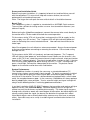
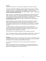
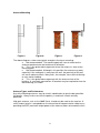
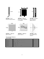
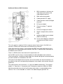
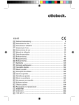
VideoWave 5.8GHz
Operation and Installation Instructions
Table of Contents
System Description
3
Survey and Installation Guide
4
Antenna Mounting
8
Antenna Types
9
Transmission Distance
9
Wireless Telemetry
10
External Weatherproof Enclosures
11
Audio and Alarms
12
Technical Notes
13
Fault Finding
15
VideoWave Specifications
16
The VideoWave system is a professional quality system designed for sending
composite NTSC or PAL video signals. All products comply with the R&TTE Directive
1999/5/EC. Models are available with various power outputs for license-free operation
in most European countries.
Due to the license-free operation of these products, there is no guarantee that
interference will not occur in a particular installation.
RDT does not assume any responsibility for the use of the products described. No
product patents are implied and RDT reserves the right to change the said products
without notice at any time.
2
System Description
The VideoWave Wireless Video Transmission is a professional system designed for
sending composite NTSC or PAL video signals using 5.8 GHz wireless technology.
Figure 1 - Transmitter connections
SMA Antenna Connector
Cable Gland for Audio/Digital
Channels
BNC Connector for Video Input
Cable Gland for DC Supply
Figure 2 - Receiver connections
SMA Antenna Connector
Cable Gland for Audio/Digital
Channels
BNC Connector for Video Output
Cable Gland for DC Supply
3
Survey and Installation Guide
Before carrying out installation, it is important to bench test and familiarize yourself
with the equipment. This manual will help with antenna choice, transmission
performance, achievable distance etc.
Note: The longer the radio path the more critical details of installation become.
Bench Test
The Videowave systems is supplied as standard with an ANT5805, Patch antenna.
These will be sufficient for testing and for use over short to medium distances (see
table on Page 9).
Before testing the VideoWave equipment, connect the camera to be used, directly to
the monitor with a 75 ohm cable and check for correct operation.
Fit the antenna to the VTX unit (transmitter) and connect the 12V dc supply (or the
mains supply in an SE version). The 7 segment LED will light indicating 'power on'
and also indicating the current selected channel. Now connect the camera to the
video input.
Note: Do not power the unit without an antenna connected. Always disconnect power
to the transmitter before connecting or removing the antenna. Failure to do so may
damage the unit.
Fit the antenna to the VRX unit (receiver) and connect the power. The 7 segment
LED will light to show 'power on' and indicate channel. Make sure the channel is the
same as the TX (if not, select the correct channel using the channel select push button
beneath the 7 segment display). The signal strength meter should also light. If the two
units are fairly close together for bench testing, all LEDs, 2 x red, 1 x orange and 3 x
green, should light. Connect the video output to the monitor. The picture should
appear on the monitor and be clear with no distortion.
System Performance
The VideoWave functions in exactly the same way as standard broadcast TV
transmissions, but on a much lower signal strength. TV aerials are normally installed
as high as possible to give the clearest signal path and achieve good reception. In
most cases if the external TV aerial is disconnected and replaced with a small indoor
aerial, the reception becomes poor. In the same way, VideoWave will always perform
best by adopting the same principle. Terrain, antenna height and signal strength will
always be the deciding factors in achieving good communications.
In an ideal installation 'LINE-OF-SIGHT' between the transmitter and receiver will give
optimum results (see Technical Notes). Obstacles blocking the line of sight will
reduce transmission distances and affect picture quality. The video signal may pass
through walls of brick or wood, with some degree of attenuation, but metal objects will
almost certainly block the signal; the denser the obstacles the greater their effect.
Note: Metal objects near or directly behind the antennas may also have an adverse
effect. If possible carry out a survey to establish good communications before final
installation.
4
Site Survey
It is advisable to carry out a survey to establish a good radio path prior to installation.
This will help with the positioning of the equipment and choice of antenna. Your
distributor should be able to assist with information and may be able to provide a
Survey Kit and antennas for this purpose.
Before commencing a survey, measure or estimate from a map, the straight-line
distance between the two sites. From the tables on page 9, check which type of
antenna would be needed to cover the required distance. Visit the sites to see if there
is a suitable location for equipment and the antennas, normally on the roof of the
building. It should also be possible to see if there is a reasonable line-of-sight
between the two locations or if there are any significant obstructions. (See Technical
Notes). A pair of field glasses may be useful if the sites are some distance apart.
Make a temporary installation of a camera and transmitter. Note: battery-operated
equipment is available for this purpose. Position the antenna and leave the equipment
running. At the receive site, set up the receiver and monitor. Position the antenna
and adjust its position to get the best signal strength indication on the receiver unit (up
to three GREEN LED's). If the picture quality is not good, or the signal strength is low,
try moving the antenna to other locations. Performance will be affected by
obstructions or metal objects nearby. Even the antenna mounting pole can cause a
problem if the antenna is not correctly mounted clear of the pole. For longer
distances, it may be necessary to use a high gain antenna on the receiver site.
Note: High gain antennas are directional and must be aimed at the transmission site
and then adjusted by rotating until maximum signal strength is achieved. The
POLARISATION of both antennas must match. For example, if the transmitting
antenna is vertical then the receiving antenna must also be vertical.
If the signal strength is too low it may be increased by raising the height of the transmit
antenna, receive antenna or both. Care must be taken, however, because there will
be a loss of signal in the cable and connectors. For the actual installation, a good
quality low-loss cable should be used between the antenna and the VideoWave units
(i.e.LMR400). Alternatively, the VideoWave unit, which is housed in a weatherproof
enclosure, can be mounted on the pole near the antenna to keep cable lengths to a
minimum.
If the picture quality is poor, even with reasonable signal strength, this may be due to
interference. Remember that this is a license free band and other users could be
transmitting in the area. If interference is suspected, try turning off the transmitter and
checking the LED signal strength meter on the receiver. Only the first red LED should
be on to indicate 'power on'. If the amber or any of the green LED's are on or
flickering, this indicates the presence of another signal. Try moving the antennas, or
changing to another channel.
5
Transmitter
Camera
Receiver
Monitor
230V Mains
Power
230V Mains
Power
Figure 3: The most common connection diagram for setting up a simple wireless
video link using the VideoWave system.
Installation
For this section, it is assumed that the equipment has been bench tested, is working
correctly and that a site survey has been completed. If not, carry out these tests
before beginning the installation.
Transmitter
Start by installing the transmitter in the required location. The transmitter can either
be located inside or outside. It is housed in a weatherproof IP67 enclosure. (See page
11)
Generally, the higher the antenna can be mounted, the better the radio performance.
There are therefore two choices; mount the transmitter high with the patch antenna
connected directly to the top of the transmitter or remotely mount the antenna using a
suitable cable.
The recommended cable, LMR400, has a loss of about 0.3dB/mtr at 5.8GHz, and you
should also allow about 0.2dB for each connector. Using these figures as a guide, the
recommended maximum cable length is about 5 metres (about 2dB loss, including
connectors). Longer cables may be used, in order to clear a building or obstruction,
but in this case it may be necessary to use a higher gain antenna to compensate for
the cable loss. (see table on page 9 for antennas and cables)
Install the camera in the required position and connect to the transmitter using a 75
ohm coax cable. Connect the power to both units.
Before leaving the transmitter site, if possible, check that the unit is working correctly
using the receiver unit connected to a monitor. It may be necessary to adjust the
camera view or lens iris to obtain the clearest picture.
6
Receiver
Installation of the receiver unit is basically a repeat of the transmitter installation.
The antenna selection will depend on the distance from the transmitter site and the
results of the site survey. The standard patch supplied is suitable for distances of up
to about 1Km maximum (depending on local conditions). Other antennas are
available for distances up to about 3Km. (see table on page 9). Note: The higher gain
antenna should be fitted to the receiver.
When the antenna is in position, before finally tightening the fixings and securing the
cable, connect the receiver unit and connect a monitor to the receiver. Check the
signal strength at the receiver using the LED indicators. All three green LED’s indicate
the strongest signal but one green LED should still give enough signal for a
reasonable picture. Try adjusting the position and direction of the antenna to give
maximum signal strength.
Check the picture on the monitor. Again adjust the antenna position if required to
obtain the best possible picture. Because of reflections and multi-path, small
movements of the antenna can have a significant effect. If interference is suspected,
try changing to another channel (this must be done on both the transmitter and the
receiver).
If a high gain antenna is being used, aim the antenna in the direction of the
transmitter. Make sure that the polarization of the two antennas match. Using the
signal strength indicator or the picture on the monitor, rotate the antenna in the
horizontal plane until the best picture is achieved.
Once the best results have been obtained fix all the equipment in position.
Note: As with the transmitter installation, cable lengths should be kept to a minimum to
reduce losses. Again, consider mounting the receiver unit close to the antenna.
General
It is important that antennas are mounted correctly and securely. Remember that on a
high pole, although the antennas are relatively small, there will still be a considerable
wind loading. If in any doubt, contact a qualified aerial rigger.
It is essential that the polarization of the transmitting and receiving antenna is
matched.
Make sure that all connections are weatherproof. This can best be achieved by
covering all connectors with a layer of self-amalgamating tape. Also make sure that
cable entries to buildings are well sealed with mastic.
7
Antenna Mounting
Figure a
Figure b
Figure c
Figure d
The above diagrams show some typical examples of antenna mounting.
a. Not recommended. The mounting pole will have an effect on the
antennas performance and could cause reflections.
b. This is the preferred arrangement where the antenna is clear of the
mounting pole.
c. Not recommended. Although in this position the antenna may work,
especially if the radio path is away from the wall, the proximity of the wall
can cause adverse effects. Many walls, for example, have steel reinforcing
or even metal cladding.
d. This is the preferred arrangement with the antenna clear of the
building. A small pole mounted on ‘A’ brackets may be required to clear the
roof overhang, as shown.
Antenna Types and Performance
Any of the following antennas may be used in combination to give the best possible
link quality. Always make sure that the polarity is matched i.e. both vertically
polarized.
High gain antenna, such as the 20dB Panel, should only be used on the receiver. A
small amount of gain is acceptable on the transmitter to compensate for cable losses
providing the ERP (maximum output power at the antenna) does not exceed the limit.
8
7.5cm
50cm
10cm
ANT5803 – Omnidirectional whip antenna.
ANT5805 – 5dB gain
patch antenna (supplied
as standard).
ANT5808 – 8dB gain
omni-directional
dipole antenna,
ANT5810 – 10dB gain
panel antenna
ANT5820 – 20dB gain
panel antenna
ANT5828 – 28dB
gain parabolic dish
antenna
Transmission Distances
(Line-of-Sight)
Antenna
Description
Distance
ANT5803
ANT5805
ANT5808
ANT5810
ANT5820
ANT5828
500mtrs
1Km
1Km
1.4Km
3Km
4Km
½ Wave Whip Omni-directional
5dB gain Patch
8dB gain Dipole Omni-directional
10dB gain Panel
20dB gain Panel
28dB gain Parabolic Dish
9
Wireless Telemetry
Telemetry for controlling PTZ cameras etc. cannot be transmitted directly over the
VideoWave but requires the addition of a Radio Modem to transmit the data. The
RM96XX series of modems is designed for use in the license free bands and is
approved for all European countries.
The modem is compatible with most commercially available video telemetry units.
Installation
The RM96XX modem can be supplied separately or mounted alongside the
VideoWave unit in an IP67 enclosure. (SED versions) Because the modem relies on
a good radio path, the installation procedure and test methods should be basically the
same as for VideoWave. It is always best to carry out a survey to ensure good signal
strength.
The 96XX modem will normally operate over a much greater distance than the
VideoWave system, therefore if a suitable site is found for the VideoWave, there
should be no problem with the modem link. Care must be taken in selecting the
correct antenna and the antenna installation. Follow the same principals as for
VideoWave.
If using remote antennas for higher gain or increased height, it is recommended to
mount the video and telemetry antennas a minimum of 3 metres apart, where
possible.
See the RM 96XX User Manual, supplied with the unit, for details on modem operation
and set-up. Application notes are available giving details of the modem settings for
most of the common telemetry systems.
RS485/
Baud
Data Stop
RS232
Rate
Bits Bits
Parity
Telemetry Manufacture/Protocol
American Dynamics (sensormatic)
RS485
4800
8
1
None
Baxall Baxnet
RS485
9600
8
1
None
BBV RS485
RS485
9600
8
1
None
BBV 20mA
RS232
1200
8
1
Even
Conway
RS485
9600
8
1
None
None
Dennard dome
RS485
9600
8
1
Dedicated Micros DS2 remote keyboard
RS232
19200
8
1
None
Honeywell Orbiter
RS485
9600
8
1
None
Honeywell KD6
RS485
9600
8
1
Even
Honeywell HRHD remote keyboard
RS485
9600
8
1
None
Mark Mercer
RS485
9600
8
1
None
Bewator/Molynx
Panasonic
RS485
RS485
9600
4800, 9600
8
8
1
1
Even
None
Pelco D
Pelco P
RS485
RS485
2400
4800
8
8
1
1
None
None
Pelco P (9600)
RS485
9600
8
1
None
Vicon
RS485
4800, 9600
8
1
None
Videoswitch Vi series DVR
RS485
9600
8
1
None
Vista DVR remote keyboard (Baxnet)
RS485
9600
8
1
None
10
Vista Powerdome
IP67 Weatherproof Enclosures
RS485
9600
8
1
None
Enclosure for VideoWave Transmitter
or Receiver
Model VTX/VRX5800S
Enclosure for VideoWave Transmitter
or Receiver
Model VTX/VRX5800SE
The enclosure has a SMA antenna
connector on the top and a BNC for
video on the bottom. Cable glands are
provided on the bottom for 12Vdc and
alarm /audio cables. (These options
are available on the 5801 versions)
The enclosure has a SMA antenna
connector on the top and a BNC for
video on the bottom. Cable glands are
provided on the bottom for mains and
alarm/audio cables. (These options are
available on the 5801 versions)
Enclosure for VideoWave Transmitter or Receiver and Radio Modem Model
VTX5800SED or VRX5800SED
The enclosure is supplied with top
antenna connectors
There is a SMA connector for the Video
antenna and a BNC for the data.
The bulkhead also has cable glands to
seal the video, data and power input
leads. There is a further gland for the
alarm and audio connections. (These
options are available on the 5801
versions)
11
Audio and Alarms (5801 Versions)
1)
BNC connector on the base for
video input (transmitter) and
video output (receiver).
2)
SMA antenna connector.
3)
Cable gland for DC supply
4)
Cable gland for audio and digital
channels.
5)
DC terminal block
6)
Channel number, 7 segment
display
7)
Channel change push button
8)
Signal strength meter (receiver
only)
9)
Audio and digital terminal block
(5801 version only)
10) Link to select digital or audio for
second channel (5801 version
only)
The units require a supply of 12V dc nominal (actual input range is 9 to 28V) at a
current of 75mA for the transmitter and 215mA for the receiver.
Video input from the camera is connected to the BNC connector on the base of the
transmitter unit. Video output to the monitor, DVR etc. is from the BNC connector on
the bottom of the receiver.
There is a SMA antenna connector on the top of each unit
On the 5801 versions there is also the option of audio and digital alarm channels.
These connections should be wired through the second cable gland and connected to
the terminal block as indicated on the PCB.
The inputs for the digital alarm channels on the transmitter are volt free contacts. On
the receiver there are corresponding changeover relay outputs with contact rating 1A
@ 30V dc
The audio input on the transmitter is 1 V p-p into 100KΩ unbalanced. The receiver
output is 1 V p-p (for a 1 V p-p input) with a frequency response of 50Hz to 15KHz.
Note that the audio channel can be linked out and used as a second digital alarm
channel. This is link selectable as shown in the above diagram, position 10.
12
Technical Notes
Propagation/Distance
For any radio link, the distance that can be achieved between sites depends on a
number of factors, the main ones being; the output power, the antenna height (above
ground), the type of terrain and ‘line-of-sight’. Line-of-sight means how clear the path
is between the two antennas, whether there are any obstructions and how dense
these obstructions are. The major effect on distance however, is the height of the
antennas above ground. The basic relationship between signal strength, antenna
height and distance is given in the following formula:Signal strength : (TX antenna height)² x (RX antenna height)²
(Distance)4
From this formula it can be seen that if the distance doubles, the signal strength
decreases to one sixteenth. In other words, to increase the distance from 1 Km to 2
Km, requires an increase in signal strength of sixteen times. It can be seen therefore
that increasing output power has a limited effect on distance.
Increasing the antenna height however, has more effect. If the antenna height (above
ground) is doubled, the effective signal strength increases four times. This is true for
either the transmitting or receiving antenna so by increasing the height of both a
significantly greater distance can be achieved.
Clear line-of-sight
When we refer to a clear line-of-sight for radio signals, this is different to a visual lineof-sight. You may be able to see the transmitting antenna from the receiver site, but
this does not necessarily mean a good radio path.
A radio signal transmitted between two antennas will spread out forming an elliptical
shape that is widest at the mid distance between the two antennas. The area within
this ellipse is known as the Fresnel Zone and any obstructions within this zone will
cause an obstruction and interference to the signal path.
TX
Fresnel Zone
Radius
RX
Note that this Fresnel Zone is three dimensional and has both height and width. The
maximum radius of the beam, at the centre, increases with the distance between the
two antennas. As a guide, at 2.4GHz the radius for a particular signal path is:
1Km signal path
4 - 5Mtr radius
2Km signal path
5 - 6Mtr radius
5Km signal path
8 - 9Mtr radius
This means for example, that if the link is 2Km long, the antennas must be at least 5 to
6 metres above the ground and above any building or obstruction. There must also be
the same 5 to 6 metres clearance to either side.
It should also be remembered that radio signals at 5.8GHz will not normally pass
through buildings and they will be severely attenuated by vegetation, such as trees.
13
Reflections
The best possible performance and therefore distance, will be achieved if there is
perfect unobstructed line-of-sight between the two sites ‘A’ and ‘B’. Even in this
situation however there is almost certain to be some degree of reflections from the
ground or nearby structures.
These reflections will have an effect on the signal strength and the final picture quality
obtained. It is useful therefore to understand the basic principals of a radio link and the
effect of reflections. The most common reflection is from the ground although other
structures, buildings etc. will have a similar effect. The reflections from these other
structures are less predictable because they depend on the shape of the structure,
construction material etc.
Consider a radio path between site ‘A’ and ‘B’ with each antenna 10 metres from the
ground. Assuming good line of sight, there will obviously be a path directly between
the two antennas, drawn as a straight line on the diagram. There may also be one or
more paths that are reflected from the ground and reach site ‘B’ indirectly via a point
on the ground, ‘X’. Obviously the distance A-X-B is longer than the direct route A-B.
The receiver at site B will receive a direct signal and a reflected signal via point X.
The effect of this reflected signal depends on its strength and the difference in length
between A-B and A-X-B. If the difference is a multiple of the wavelength
(approximately 12.5cm for 2400) the reflection is 180º out of phase and will reduce the
received signal strength. In fact if both signals were the same strength they would
cancel and no signal would be received.
Because at these frequencies the wavelength is quite short, even a small adjustment
in antenna height can affect the path length of the reflected signal and so change the
received signal strength. By raising the antenna gradually it will cycle through a
regular pattern of in phase and out of phase signals giving a corresponding pattern of
reduced and increased signal strength.
14
Interference
Because the 5.8 GHz frequency band is an unlicensed public access bands, there is
no control on other users. It is therefore possible that another user could be operating
on the same frequency in your area. If this is suspected, turn off the transmitter and
see if there is any activity on the LED’s of the receiver. If there is a transmission on
the same frequency the amber or green LED’s should light or flash indicating the
received signal.
If there are other users it may be possible to avoid interference by changing channels
or by repositioning the antenna. A directional antenna may also reduce the effect.
The reflected signal will show up as ghosting on the monitor. Occasionally this may
be seen in adverse weather conditions when a signal may be reflected from rain,
snow, dense cloud or fog.
Fault Finding
No LED's illuminated
Venetian blind effect
Low or no signal strength
Snowy or grainy picture
Picture rolling or tearing
Possible solution
Check power supply.
TX – 7 segment channel indicator should be on.
RX – 7 segment channel indicator should be on, plus
the first red LED of the signal strength meter
Incorrect voltage from power supply. Should be 12V on
–S versions
Check video input on transmitter. See pages 5 and 13
regarding antenna height and position.
Weak signal. Check number of GREEN LED's on VRX
units signal strength meter. See pages 5 and 13
regarding antenna height and position.
Reflections. See page 13
Check output voltage from camera. Should be 1V p-p
15
Specification
General
Video Input
1V p-p into 750ohm BNC
Video Output
1V p-p into 750ohm BNC
Operating Voltage
240V AC
Protection
Reverse Polarity
Power Consumption @ 240V AC
Transmitter
1W
Receiver
2.6W
Antenna Connector
50ohm SMA (Female)
Power Connector
Screw terminal
Indicators
Channel / ON
7 segment display
Signal Strength (RX)
LED bar graph
Radio Modem
Frequency Range
Channel Spacing
No. of Channels
Transmitter
RF Power Output
Adj. Channel Power
Freq. Tolerance
FM Deviation
Receiver
RF Sensitivity
Intermodulation
406-470MHz*
25KHz
32
50-500mW (4 steps)
-37dBm
+/- 1KHz
+/- 3.5KHz
-110dBm for 10BER
-70dB
Radio
Frequency range
RF Power Output
Local Oscillator
Modulation Type
Modulation Bandwidth
Adj. Channel Rejection
RSSI Threshold Level
Max Bit Rate
Modulation
Interface Baud Rate
Parity
Power Consumption at 240V
Transmitter at 500mW
Receiver
5725 – 5875MHz
25mW ERP
PLL Synthesised
FM
4.5MHz
-70dB
-105dBm 16k
-110dBm at 8k
16kbps
GMSK
150-19.2 Kbaud
Odd, Even, None
7.2W
4.2W
* UK Specification is 15 channels 458.525 to 458.925MHz
Mechanical
Dimensions
Height*
Width
Length
255mm
180mm
80mm
Weight
Enclosure
Mounting
1.8kg
Polycarbonate IP67
4x7mm diameter holes
Spacing 238.5x163.5
Operating Temperature
-10 to +55°C
*Excluding connectors and cable glands.
Equipment conforms to the R&TTE Directive 1999/5/EC
Radio Data Technology Ltd
10-11 Taber Place Crittall Road Witham Essex CM8 3YP England
Telephone: 0044 (0) 1376 501255 Telefax: 0044 (0) 1376 501312
Email: [email protected] URL: www.radiodata.co.uk
A member of the CML Microsystems Plc group
16