1
G T 6 0 0 / 6 0 1
Control Panel
Engineer’s
Reference Guide
IMPORTANT INFORMATION
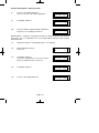
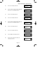
1)
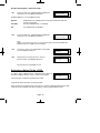
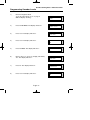
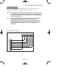
Twenty Minute Timer (Wireless Receiver version 1.29 or later required for this function)
When this option is switched on, any wireless zone that has not reported to
the panel within 20 minutes will be regarded as not ready (open).
[Programming][Zones][Wiring][Radio Functions][Receiver Functions] {20-Min Timer}
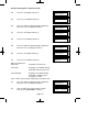
2)
Attenuation (Wireless Receiver version 1.29 or later required for this function)
When this option is switched on, allocating a wireless zone device (installing)
will have its RF reception dampened by the panel. This is to comply to
EN50131 standard when enrolling wireless devices.
[Programming][Zones][Wiring][Radio Functions][Receiver Functions] {Attenuation}
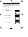
3)
Battery Disconnect
This feature is a warning feature that will occur upon exiting engineer mode in
order to check that a lead acid battery is infact connected.
This option is not programmable.
The option is always on.
In order to check the Battery Charge Voltage see page 121.
Note 1: Please ensure that all wireless transmitters are set to 15 minute
supervision.
Note 2: Wireless Receiver V1.29 will also function on older panel versions,
but will not have the ‘Twenty Minute Timer’ or ‘Attenuation’ ability.
GT 600 / 601 Engineer’s Reference Guide
CONTENTS
1 INTRODUCTION ............................................................2
2 Resetting Factory Defaults ...................................2
3 Programming .........................................................6
Moving Around ...............................................6
Headers & Options ........................................6
Common Options With Menu Numbers..........9
Programming Zones ......................................11
Programming Setting Modes .........................30
Programming Entry Times .............................37
Programming Bells / Sounders ......................39
Programming Keypad ....................................43
Programming Digicom / STU / Vo-Comm.......46
Programming Linefault Modes ......................57
Programming Panic / Duress ........................59
Programming PGM2 / PGM3 / Timers............61
Programming Reset Modes ...........................65
Programming Sounder Levels .......................67
Programming PGM 1 / XP / Custom .............69
Programming Engineer Code ........................72
Programming Service ....................................73
Programming Custom Screens .....................76
Programming Diagnostics / Log ....................77
Programming Alarm Confirm (Notes) .............81
Programming Alarm Confirm .........................84
NovActive Description & Programming ..........89
Programming Point ID Protocol ......................92
Engineer Reset...............................................95
Linefault Sounders Description ......................96
Clearing Test Fail Indication ...........................97
Programming ID Biscuits ................................98
Specifications .................................................102
Installing 4 Wire Keypad.................................105
Wiring Diagrams .............................................106
4
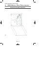
B26 Metal Box. Accessories Assembly Inst.......118
Checking Battery Charge Voltage ..................121
Gardtec 600 PCB fitting instructions ..............122
Page 1
GT 600 / 601 Engineer’s Reference Guide
1 INTRODUCTION
The GT 600 / 601 control panels use 32 character LCD Remote Keypads for control of
the system via User Code(s) and programming of the system via an Engineer Code.
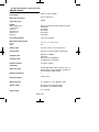
The Factory Default Codes are.
Note: GT 600 / 601 Control Panels can only be programmed using LCD KEYPAD.
Default Master User Code
Default Engineer Code
BS / EN2 5678
BS / EN2 1234
EN3 005678
EN3 001234
Note: For EN3 installations, User Codes and Engineer Codes MUST be six
digits in length.
The Engineer code may be ‘Locked’ into the system during engineer
programming. It should be noted that if the ‘Locked’ code is not known the only
way to have it returned to the factory default is to return the PCB to the factory.
Option Formats. When an option cannot be changed the display will show a : rather
than the usual = sign. Pressing the No key is disregarded and the panel will react as
though the Yes key has been pressed (i.e. it will move onto the next option).
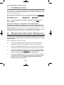
2 RESETTING FACTORY DEFAULTS
Several reset to factory default routines are available to the engineer at system powerup but it should be noted that none of these routines will ‘Un-Lock’ a ‘ Locked’
Engineer Code.
The following default routines are available.
a)
Pressing 1, 9, YES, NO during initial power up will revert the Master Code
and Engineer Code (not locked engineer code) back to factory defaults.
b)
Pressing 3, 7, YES, NO during initial power up will revert all system settings
back to defaults with the exception of the User Names and Zone Descriptors.
c)
Pressing 4, 6, YES, NO during initial power up will revert all system settings
back to factory defaults. It is ESSENTIAL that a 4 6 Yes No Reset is done
to all new systems before commencement of programming.
d)
Pressing 5, 5, YES, NO during initial power up will revert all system settings to
factory defaults and will also set the comms options up for GardTec Remote.
ie Modem On; No Return. For commissioning systems for use with
GardTec Remote, use this option.
Page 2
GT 600 / 601 Engineer’s Reference Guide
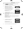
Reset of the factory defaults and entering Engineer Mode:Note:
It is ESSENTIAL that a 4 6 Yes No reset is done to all new systems
before commencement of programming.
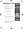
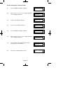
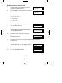
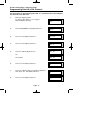
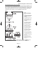
1)
Remove all power from the system for at least ten seconds
2)
Apply mains power to the control panel.
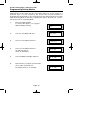
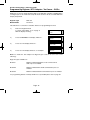
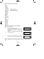
The display will show, for example:(Display will differ depending on panel version)
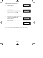
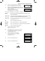
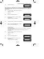
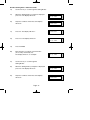
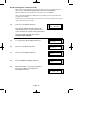
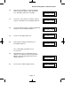
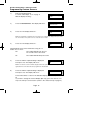
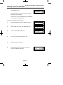
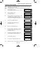
3)
Gardtec60x
Version
xx-xx
Whilst this display is showing (the first five
seconds) press the keys shown in a, b, c or d
for the reset required. (E.g. 4 6 Yes No).
The display will show:This may show for several minutes.
Please Wait
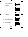
4)
The display will then show:The display may differ from the sample shown.
Select Standard
1:BS 2:EN2 3:EN3
Note:
Due to changes within the standards, the GT600 is only BS or EN2
(GRADE 2) compliant.
Selecting 1:BS - Panel may be programmed to comply with the old BS4737 Standards. DD243
requirements will still apply.
Selecting 2:EN2 - Panel may be programmed to comply with EN50131-1 for Grade 2 Systems.
DD243 requirements will still apply.
Selecting 3:EN3 - Panel may be programmed to comply with EN50131-1 for Grade 3 Systems.
DD243 requirements will still apply
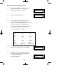
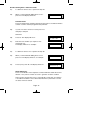
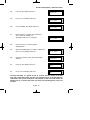
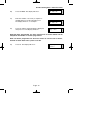
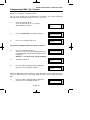
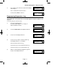
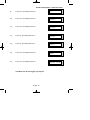
5)
Select 2:EN2.The display will then show:This may show for several minutes.
The display will then show:From Control Panel Version 2 ONLY.
6)
Please Wait
Select PD6662
1: 2004
2: 2010
Select either 1 or 2 depending on which standard you require.
Page 3
GT 600 / 601 Engineer’s Reference Guide
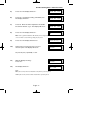
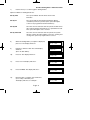
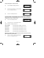
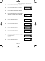
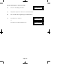
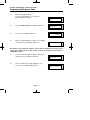
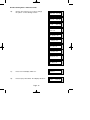
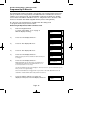
7)
The display will show:This may show for several minutes.
8)
Enter Engineer code.
(1234 default EN2). The display will show:-
Please Wait
Enter Authorisor
Code . . . . . .
Note: User Codes and Engineer Codes MUST be six digits in
length for EN3 installations. (See Page 2).
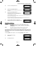
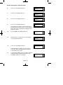
9)
Enter the Authorisor code. The Authorisor code is
the Master User, (default 5678 EN2).
The display will show:-
Do you want to . .
Use ENGNR. Mode ?
Note: It may be required that an engineer has to be authorised by a user before access to the
Engineer mode is granted.
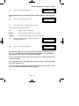
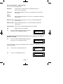
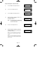
10)
Press Yes. The display will show:-
Program Zones . . . . - - Zones ?
From this point the panel is in Engineer Mode and all Tampers will be disabled.
Page 4
GT 600 / 601 Engineer’s Reference Guide
Note:
At any point when three underscores are shown on the display, you are
viewing a Header. You may move to the next Header by Pressing the NO
Key or access the functions under the Header by Pressing the YES Key.
Note:
You are able to jump to various common options when programming by
entering the relevant menu numbers. With a Header showing, key in the
appropriate menu number, then press Yes. (See page 9).
Page 5
GT 600 / 601 Engineer’s Reference Guide
3 PROGRAMMING
Moving Around
Enter Engineer mode as described on page 3.
The display will show:Program . . . .
Zones ?
___
Whenever three underscores are shown on the display the screen is a Header.
Pressing the NO key will move to the next Header.
Pressing the YES key whilst viewing a Header will enter into the options under that
Header.
Pressing 0 will escape back one step (except when a numeric entry is required).
You are able to jump to various common options when programming by entering the
relevant menu numbers. With a Header showing, key in the appropriate menu
number, then press Yes. (See Pages 9 & 10 for Common Options with Menu
Numbers).
Below is given a complete list of headers (Shown in Bold Underline) and options that
appear under each header.
Headers & Options
Headers & Options
Program Zones
Entry Times
Zone Types
Zone Descriptors
Zone Wiring
Zone Attributes
(Test/Part/Cleaner/Chime/Walk/Sec/Per)
Zone Double Knock/Arm/Log
Zone E/E Mode
Event Tags
Entry Time 1
Entry Time 2
Setting Modes
Bells / Sounders
Bell Type
Bell Delay/No Arms
Bell & Sounder Ring
Bell Tamper Mode
Bell For Part Set
Setting For Full Sets
Setting For Part 1 Sets
Setting For Part 2 Sets
Setting For Part 3 Sets
Setting Delay
Setting Sounders
Setting Conformation
Auto Part Set
Page 6
GT 600 / 601 Engineer’s Reference Guide
Headers & Options
Headers & Options
Keypad / Keyswitch
Reset / Mains
Keypad Alert 1 Keys
Keypad Alert 2 Keys
Function Keys
Keypad Alert 3 Keys
Number of Keypads
Keypad Backlight Mode
ACE / Prox
Area/s
Mains Fail Delay
Alarm 1 Reset (Area 1)
Alarm 2 Reset (Area 2)
Alarm 3 Reset (Area 3)
Alarm 4 - 7 Reset (Areas 4 - 7, 601 ONLY)
Tamper Reset
Alarm Restore On/Off
Abort Time
Digicom
Sounder Levels
Type or Test
Vo-Comm
STU Adaptor
Start Delay / Part
Channels
Digicom/Modem Functions
Chime Level
Entry/Exit Level
Keypad Beep Level
Line Fault Modes
PGM1 O/P
Expander 1 O/P 1 - 4
Expander 2 O/P 1 - 4
Expander 3 O/P 1 - 4
Expander 4 O/P 1 - 4
Custom Output 1
Custom Output 2
Custom Output 3
Custom Output 4
Custom Output 5
Custom Output 6
Custom Output 7
Custom Output 8
PGM1 / XP / Custom
Line Fault Sounders
Line Fault Mode in Exit
Line Fault Log Mode
Line Fault Detect Time
Panic / Duress
PA Mode / Bells Only / Bells Always
Silent Always / Bells if Line Fault
Testable / Non-Testable
Duress Off (To conform with EN standards, Duress
is defaulted to Off and cannot be changed)
Engineer Code
PGM2 / PGM3 / Timers
Engineer Code
Engineer Code Locked/Unlocked
PGM2/3 Operating Mode
Timer 1 On Time
Timer 1 Off Time
Timer 2 On Time
Timer 2 Off Time
Timer 3 On Time
Timer 3 Off Time
Page 7
GT 600 / 601 Engineer’s Reference Guide
Headers & Options
Service
Mains OK 50Hz
Save Panel NVM to PTM
Load Panel NVM to PTM
Service Timer On/Off
Time To Next Service
Service Tel No.
Lock-Out On/Off
Engineer Mode Constant/Timed
Custom Screens
LCD Status Display
Headers & Options
Alarm Confirm
Window Time
On Entry
Sounder Mode
Reset Mode
Secondary Time
ET Mode
Bell Mode
Strobe Mode
Start Delay
Comms Restore
Keypad Opening
ACE Battery Monitor
(To conform with EN standards, LCD Status is
defaulted to Off and cannot be changed)
LED Status Display
Custom Display On/Off
Program Text
Diagnostics / Log
List Event Log
Change List Diagnostics
PSU Diagnostics
NovActive Diagnostics
PSU Test Time
Change / List Test Limits
Aux Volts
Battery Volts On Charge
Battery Volts Off Charge
In conclusion, the Yes and No Keys are used to navigate. The No Key is also used to
change a value (may also require a numeric input) and the Zero Key is used to move
back a level (not when the display is expecting a numeric input).
If you are confident in programming the GT 600 / 601 Control Panels please use the
headers and options above to continue or alternatively use the appropriate menu
numbers. (See Pages 9 & 10).
Otherwise
Please continue with the next section for a Step by Step Guide to programming the GT
600 / 601 Control Panels.
Only the major options will be covered in this Step by Step Guide. After
completing the guide you should be confident to program the remaining options.
Page 8
GT 600 / 601 Engineer’s Reference Guide
Common Options With Menu Numbers
You are able to jump to various common options when programming by entering the
relevant menu numbers. With a Header showing, key in the appropriate menu
number, then press Yes.
Menu
1
6
8
9
10
11
12
13
14
15
20
21
22
23
24
26
27
28
29
30
34
35
37
38
40
41
42
44
46
47
48
50
51
52
53
54
55
58
64
65
66
67
68
Jumps to
Menu
PGM 2/3 Output
PA Mode
Chime Level
Entry Exit Level
Exit Sounder Mode
Final Set Delay
Full Set Setting Time / Setting Mode
Part 1 Set Setting Time / Setting Mode
Part 2 Set Setting Time / Setting Mode
Part 3 Set Setting Time / Setting Mode
Alert 1 Keys Mode / On Off
Alert 2 Keys Mode / On Off
No. of Keypads / Multi On Off / K/Switch
Bell Delay / No. of Bell Arms
Bell Ring Time / Sounder Mode
NovActive On Off
Bell Tamper Ring On Off
Entry Time 1
Entry Time 2 / Warning Bell
Digi Delay / Part Alarm Digi
Digicom Type
Key Beep Level
Zone Re-Arm / Double Knock Time
Engineer Code
Line Fault Sounders
Line Fault Mode
Line Fault Log
PGM 1 Output
Main Fail Delay
Tamper Reset Mode
Backlight Mode
Zone Response
Zone Types
Test Zone (Attributes)
Service Timer On Off
Service Due Weeks
Zone Log Limit
Digicom Channels
Alarm Restore / Abort Time
Test Digicom Channels
E/E Zones in Part Set
Engineer Code Locked / Unlocked
Strobe Confirm
69
70
71
72
73
75
76
77
78
79
83
84
86
88
90
93
94
97
101
102
107
109
110
111
112
113
114
115
116
117
118
129
131
139
153
155
156
157
158
159
160
161
162
Page 9
Jumps to
Auto Part Set
Part Set Bells
Zone Types ( Enter Zones)
On Board EOL
ID map (expansion type ZEX/ID first)
ZEX1 Wiring
ZEX2 Wiring
ZEX3 Wiring
ZEX4 Wiring
ZEX5 Wiring
Expander 1 O/P1 Mode
Timer 2 On Time
Timer 2 Off Time
Timer 3 On Time
Timer 3 Off Time
Custom Display
Custom Text
List Event Log
Alarm A2 Reset
Alarm A3 Reset
Bell Ring A2 / Bell Ring A3
Bell Delay A2
Bell Delay A3
F-Exit Time A2
P1-Exit Time A2
P2-Exit A2
P3-Exit A2
F-Exit A3
P1-Exit A3
P2-Exit A3
P3-Exit A3
Walk / Bypass
NovActive
PSU Test Time
Test Zones
Confirm Time Window (DD243 Section)
Secondary Time Window
Confirm on Entry On Off
Sounder Trigger
Unconfirm Reset Mode
E/T Mode
Bell Trigger
Confirm Start Delay
GT 600 / 601 Engineer’s Reference Guide
Menu
164
165
166
167
168
169
170
171
172
173
174
Jumps to
Strobe Timer
Strobe Trigger
Custom 1 OP Mode
Custom 2 OP Mode
Custom 3 OP Mode
Custom 4 OP Mode
Custom 5 OP Mode
Custom 6 OP Mode
Custom 7 OP Mode
Custom 8 OP Mode
Comms Restore On Off
Page 10
GT 600 / 601 Engineer’s Reference Guide
Programming Zones
1)
With the display showing:-
2)
Enter the Engineer code (1234 default EN2)
The display will show:-
Enter Au horisor
Code . . . . . .
3)
Enter the Authorisor code. The Authorisor code is
the Master User, (default 5678 EN2).
The display will show:-
Do you want to . .
Use ENGNR. Mode ?
01 Jan
00: 00: 01
4)
Press YES. The display will show:This is Engineer Mode
Program . . . .
Zones ?
5)
Press Yes. The display will show:-
Program Zone
Types ?
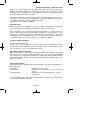
6)
Press Yes. The display will show:-
Enter Zone #
7)
Enter the zone number you wish to program
e.g 1 followed by Yes. The display will show,
for example:-
8)
Press No. The display will show:-
9)
Note the chevron has now appeared before
the Zone Type. Now press the No key until the
Zone Type you require is displayed.
Page 11
___
_ _ _
001 = Ent/Ex
A=
1
= Remove -
001 > Ent/Ex
A=
1
= Remove -
GT 600 / 601 Engineer’s Reference Guide
Zone Types available are:12 Hour
Full Alarm if Control Panel is Set.
Access
Will allow to pass through on exit.
Will allow to pass through on entry only if E/E is opened first.
24 Hour
Internal Sounder if Unset.
Full alarm if Set.
Remains active in Engineer Programming Mode.
Entry/Exit (or E/E)
Zone used as last exit point (will terminate exit time if setting mode is set to
E/E or Time+E/E).
Will start E/E time if opened when Control Panel is Set
Part E/E
As Access if Control Panel is Full Set
As Entry/Exit if Control Panel is Part Set
Panic
24Hour Personal Attack (or Panic Attack). Active if Control Panel is Set,
Unset or in Engineer Programming Mode . May only be tested via Engineer
code if programmed as testable.
Alert
Internal Sounder Only, Recorded to Log when Unset
Recorded to Log when SET
Fire
Will give Fire alarm when activated (pulsed sounders) with Control Panel Set
or Unset.
Remains active in Engineer Programming Mode.
ET
Exit terminator. Used for final setting of the system. Exit Mode must be
programmed for ET.
Monitor
Will write to the log once only in any one set or unset unless chime is
allocated then all activations are written to the log.
KSW Bat
When used, zone should be connected to the trouble/status output of third
party radio equipment that is capable of giving a low battery signal.
Line Fault
When used, acts as a Line Fault input to the control panel.
Fault
When used, will act as an Fault input to the control panel when an internal
fault has been detected within the PIR.
Mask
When used, will act as an input to the control panel if the detector has been
blocked or covered.
Note: Fault and Mask are treated as 24Hr but trigger a Fault Sound in Day (Unset) Mode. The Fault
sound is a three tone sounder.
Page 12
GT 600 / 601 Engineer’s Reference Guide
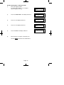
10)
When you are satisfied with your selection
press Yes. The display will show for example:-
11)
All Zones are Area 1 by default. Use the 1, 2 & 3
(keys 4 to 7, 601 ONLY) keys to add or remove the
zone to other Areas.
When you are satisfied press Yes.
The display will show, for example:-
001 = Ent/Ex
A>
1
= Remove -
001 = Ent/Ex
=A
123
> Remove -
We will now be changing the Zone Tag options, available are:Remove-
The zone may not be Removed (Omitted) by the end user. (Part
Sets are still allowed).
Remove+/DK
Zone may be Removed (Omitted) by the end user and is a Double
Knock Zone (2 activations required within time window).
Remove-/DK
Zone may not be Removed by end user (Part Sets are still allowed)
and is Double Knock Zone.
Off
Zone is turned Off (Use with caution).
Norm Key
Zone is a Keyswitch Zone for a normal type Keyswitch.
Bias Key
Zone is a Keyswitch Zone for a Bias (momentary) type Keyswitch.
Remove+
Zone may be Removed by end user.
12)
Press No until the setting you require is
displayed, then press Yes.
13)
The display will show the next zone to program.
You should repeat from Step 8 until you have
programmed all the zones.
14)
When all required Zones have been
programmed press 0 (zero) key twice.
The display will show:-
Program Zone
Types ?
15)
Press No. The display will show:-
Program Zone
Descriptors ?
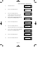
16)
Press Yes. The display will show:-
Page 13
Enter Zone #
_ _ _
GT 600 / 601 Engineer’s Reference Guide
17)
Enter the Zone number you wish to
program the Descriptor for, followed by Yes.
The display will show, for example:-
Zone 001 Name =
Zone 001
Zone 001 Name >
_
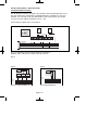
18)
Press No. The display will show:-
19)
You should now program the Descriptor you
require using the template below for the
key allocation, in a similar way that you you would
type a text message on a mobile telephone.
As the desired character is displayed press the
Yes key to move on to the next character.
Continue until the line is complete.
20)
21)
1
ABC
2
DEF
3
GHI
4
JKL
5
MNO
6
PQR
7
STU
8
VWX
9
YZ Space
No
Delete
0
1234567890
Yes
Enter Character
As you enter the last character the display
will move on to the next Zone. For example:-
Zone 002 Name =
Zone 002
Repeat from Step 18 until all the Descriptors
you require have been programmed. Then
press 0 (zero) key twice.
Program Zone
Descriptors ?
The display will show:-
Page 14
GT 600 / 601 Engineer’s Reference Guide
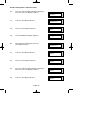
22)
Press No. The display will show:-
Program Zone
Wiring ?
23)
Press Yes. The display will show:-
Zone Response
:400 mS
Note: Zone Response time is defaulted to 400ms and may not
be changed.
24)
Press Yes. The display will show:Note: Fault /Mask response time may be programmed as a
global parameter and may be reprogrammed from 2 to 14
seconds. (increments of 2 seconds).
Fault / Mask Zones
Response=Norm
The time programmed for this option will apply to all zones, there is no option for individual response
times per zone. It is a global setting.
Once the Fault / Mask as been triggered the response time for the Fault / Mask will revert to the
default time of 400ms until the fault / mask problem has cleared.
25)
Press No until the settings you require are
displayed. Then press Yes. The display will show:-
On-Board Zones
=8 <EOL>
Wiring Modes available are:8 (2 Wire)
Two wires are used for the zone and a global tamper is used.
(Depending on Version / Grade - Cannot be used in Grade 3
installations).
(EOL)
Two wires are used in conjunction with two resistors to give
End Of Line wiring, this is the most secure wiring format.
For information on how to wire the various wiring modes, please refer to the
back of this manual, or refer to the Quick Start Guide that is supplied with the
control panel.
If selecting 8(EOL) follow steps 26 - 28. If selecting 8(2 Wire) jump to step 29.
26)
With the display showing:Press Yes.
On-Board Zones
=8 <EOL>
27)
The display will show:-
On-Board EOL
=Norm
Page 15
GT 600 / 601 Engineer’s Reference Guide
Three wiring options are available under 8 (EOL):
Norm:
Standard GardTec wiring configuration without Mask or Fault detection.
Note: Does not give any Fault or Masking detection and should only be used with Zone pairing.
ELF1:
ELF1 wiring is used for detectors that have a relay output (a pair of terminals)
for Fault or Mask.
ELF2:
ELF2 wiring is used for detectors that have a transistor output (a single
terminal) for Fault or Mask.
Note: We would recommend that either ELF1 Format or ELF2 Format (depending on detector output type,
Relay or Transistor) is used. ELF1 or ELF2 wiring modes will allow for Alarm, Tamper, Fault and Masking to be
monitored from a single zone without the need for zone pairing. Please see the back of this manual or refer to
the GT 600 / 601 Quick Start Instructions.
Note: The installer should check what output type the detector are, noting that all the detectors should be of the
same type with regards to the Fault / Mask output.
28)
Press No until the setting you require is displayed,
then press Yes. The display will show:(Jump to step 33).
Zone Expansion
= ZEX
If 8(2 Wire) wiring option is required. (Version dependant).
29)
With the display showing:Press No until 8(2 Wire) is displayed.
On-Board Zones
=8 <EOL>
30)
The display will show:-
On-Board Zones
>8 <2-Wire>
31)
Press Yes. The display will show:-
On-Board Pairing
= Off
Page 16
GT 600 / 601 Engineer’s Reference Guide
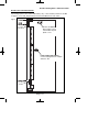
Zone Pairing.
If the 8(2 Wire) wiring mode is used then a zone must be used to monitor for Masking and Fault.
This is achieved by selecting Zone Pairing as on. Zone Pairing cannot be used in ELF1 or ELF2
wiring modes.
When using Zone Pairing each zone will have a corresponding paired zone that will be used for
Masking and Fault signals. This is done by using the Odd numbered zones for the normal alarm
detection and the Even numbered zones for Masking and Fault Detection. For example.
Alarm Zone
Zone 1
Zone 3
Zone 5
Zone 7
etc...
Pared Zone for Mask / Fault
Zone 2
Zone 4
Zone 6
Zone 8
Please note that half the zones on the system would be lost for processing the Mask and Fault
signals and it would be more prudent to use the ELF1 or ELF2 modes as described previously.
32)
Press No until the setting you require is displayed.
Then press Yes. The display will show:-
Zone Expansion
= ZEX
Options available are:ZEX
= Standard GardTec Zone EXpanders. (Are all defaulted to EOL with the same options
that are available for the on-board zones).
ID
Note:
= ID Expander card using ID Biscuits.
When using ID Expansion, Radio cannot be used.
Please refer to page 98 for programming ID Expanders.
33)
With the display showing:Press Yes.
34)
The display will show:-
Zone Expansion
= ZEX
Radio ZEX
> Off
Page 17
GT 600 / 601 Engineer’s Reference Guide
35)
If you are not using Radio Detectors press Yes
and jump to Step 37.
Otherwise
Press No until the display shows:-
Radio ZEX
= On
Comprehensive instructions on how to setup and program the Radio Expansion
are given in the document Hybrid Wireless Set-Up & Programming Guide
(document number PR5588) supplied with the Radio Receiver.
36)
Press Yes. The display will show:-
Program Radio
Functions ?
37)
Press No. The display will show:-
ZEX 1 Wiring
= Off
Options available are.
Off
Expander Card is turned Off
4 (4 Wire)
Expander will give 4 zones + 4 tamper zones
8 (EOL)
Two wires are used in conjunction with two resistors to give
End Of Line wiring. Expander will give 8 End Of Line zones. This is
the most secure wiring format.
8 (2 Wire)
Two wires are used for the zone and a global tamper is used.
(Depending on Grade - Cannot be used in Grade 3 installations).
Page 18
GT 600 / 601 Engineer’s Reference Guide
38)
Press No until the required setting is displayed
then press Yes. The display will show:-
39)
Press No until the required setting is displayed
then press Yes. The display will show:-
40)
Repeat from Step 39 until all the ZEX Expanders
you require have been programmed.
The display will show:-
ZEX 1 Pairing
= Off
ZEX 2 Wiring
= Off
Program Zone
Wiring ?
41)
Press No. The display will show:-
Program Zone
Attributes ?
42)
Press Yes. The display will show:-
Test None
Any 12Hr type zone(s) may be placed on Test. A Zone on Test will never trigger
an alarm or send a central station signal. If the Zone(s) fails the Test when the
system is Set, the display will show Test Fail when the user Un-Sets the system.
After 20 successful Sets and Un-Sets, the Zone(s) will be taken out of Test by the
system.
Page 19
GT 600 / 601 Engineer’s Reference Guide
43)
If you do not wish to put a Zone(s) on Test press
Yes and jump to Step 48.
Otherwise
44)
Press No. The display will show:-
45)
Enter the Zone number you wish to place on test
followed by Yes.
The display will show for example:-
46)
To add more Zone(s) to the test repeat from
Step 44.
47)
When you have finished adding Zones to Test
press Yes.
48)
The display will show:-
Enter Zone # _ _ _
then +YES or -NO
Test 003
Pt-1 None
Page 20
GT 600 / 601 Engineer’s Reference Guide
Three Part Sets are available on the GT 600 / 601 control panels. Zones added to
the PT-1 (Part 1) screen will be Removed (Omitted) when the system is Part 1
Set. Zones added to the PT-2 (Part 2) screen will be Removed (Omitted) when
Part Set 2 is used. When Part Set 3 is used Parts 1 & 2 are combined and
Removed (Omitted).
49)
If you do not wish to enter PT-1 Zone press Yes
and jump to Step 54.
Otherwise
50)
Press No. The display will show:-
51)
Enter the Zone number you require for PT-1
followed by Yes.
The display will show for example:-
52)
To add more Zones to PT-1 repeat from Step 50.
53)
When you have finished adding Zones to PT-1
press Yes.
54)
The display will show:-
Enter Zone # _ _ _
then +YES or -NO
Pt-1 004
Pt-2 None
Page 21
GT 600 / 601 Engineer’s Reference Guide
55)
If you do not wish to enter PT-2 Zones press Yes
and jump to Step 60.
Otherwise
56)
Press No. The display will show:-
57)
Enter the Zone number you require for PT-2
followed by Yes.
The display will show, for example:-
58)
To add more Zones to PT-2 repeat from Step 56.
59)
When you have finished adding Zones to PT-2
press Yes.
60)
The display will show:-
Enter Zone # _ _ _
then +YES or -NO
Pt-2 005
Clnr None
Zones entered as Cleaner will be removed (Omitted) when a Part Set 0 is
performed and will be included into the system (protected) when a Cleaner level
code is entered.
Or
When a system is Full Set and a Cleaner level code is entered the Cleaner zones
will be removed (Omitted).
61)
If you do not wish to enter Clnr Zones press Yes
and jump to Step 66.
Otherwise
62)
Press No. The display will show:-
Page 22
Enter Zone # _ _ _
then +YES or -NO
GT 600 / 601 Engineer’s Reference Guide
63)
Enter the Zone number you require for Clnr
followed by Yes.
The display will show, for example:-
64)
To add more Zones to Clnr repeat from Step 62.
65)
When you have finished adding Zones to Clnr
press Yes.
66)
The display will show:-
Clnr 007
Ch1 None
Two Chime suites are available on the GT 600 / 601 control panels. So, for
example, you would have the Front Door on Zone 1 programmed into Ch1 and
the Rear Door on Zone 6 programmed into Ch2. When the system is Unset,
opening the Front Door will produce a Chime. Opening the Rear Door will
produce a different Chime.
It should be noted that Chime must be programmed as On from the user mode.
Please refer to the User Manual for details.
67)
If you do not wish to enter Ch1 Zone press Yes
and jump to Step 72.
Otherwise
68)
Press No. The display will show:-
Page 23
Enter Zone # _ _ _
then +YES or -NO
GT 600 / 601 Engineer’s Reference Guide
69)
Enter the Zone number you require for Ch1
followed by Yes.
The display will show for example:-
70)
To add more Zones to Ch1 repeat from Step 68.
71)
When you have finished adding Zones to Ch-1
press Yes.
72)
The display will show:-
73)
If you do not wish to enter CH-2 Zones press Yes
and jump to Step 78.
Ch1 001
Ch2 None
Otherwise
74)
Press No. The display will show:-
75)
Enter the Zone number you require for Ch2
followed by Yes.
The display will show for example:-
76)
To add more Zones to Ch2 repeat from Step 74.
77)
When you have finished adding Zones to Ch2
press Yes
Page 24
Enter Zone # _ _ _
then +YES or -NO
Ch2 006
GT 600 / 601 Engineer’s Reference Guide
78)
The display will show:-
Walk None
Zone programmed as Walk will have to be Walk Tested before the system will
start to Set. The Option ‘Walk’ must also be programmed to On in the Zone E/E
Mode section.
79)
If you do not wish to enter Walk Zones press Yes
and jump to Step 84.
Otherwise
80)
Press No. The display will show:-
81)
Enter the Zone number you require for Walk
followed by Yes.
The display will show for example:-
82)
To add more Zones to Walk repeat from Step 80.
83)
When you have finished adding Zones to Walk
press Yes. The display will show:-
Enter Zone # _ _ _
then +YES or -NO
Walk 002
Sec. None
Secondary Zones:
Zones programmed as secondary will not active any sounders or comms until
a normal zone activates.
This will then trigger a confirmed signal and activate the sounders as
programmed.
84)
If you do not wish to enter Sec. Zones press Yes
and jump to Step 89.
Otherwise
85)
Press No. The display will show:-
86)
Enter the Zone number you require for Sec.
followed by Yes.
The display will show for example:-
Page 25
Enter Zone # _ _ _
then +YES or -NO
Sec. 002
GT 600 / 601 Engineer’s Reference Guide
87)
To add more Zones to Sec. repeat from Step 85.
88)
When you have finished adding Zones to Sec.
press Yes. The display will show:-
Per. None
Perimeter Zone:
Zones programmed as perimeter will activate the alarm as normal but will also
activate a comms channel programmed as perimeter.
89)
If you do not wish to enter Per. Zones press Yes
and jump to Step 94.
Otherwise
90)
Press No. The display will show:-
91)
Enter the Zone number you require for Per.
followed by Yes.
The display will show for example:-
Enter Zone # _ _ _
then +YES or -NO
Per. 002
92)
To add more Zones to Per. repeat from Step 90.
93)
When you have finished adding Zones to Per.
press Yes. The display will show, for example:-
Test None
94)
Press 0 (zero), then No. The display will show:-
Program Zone
DKnock / Arm / Log ?
DKnock/Arm/Log:
Zones on double knock are required to activate within the double knock time
window or stay active for fifteen seconds to generate an alarm condition.
Arm is used to program the zones to automatically re-arm after an activation.
It should be noted that a zone still violated when the system times out after
an alarm, will not re-armed.
Page 26
GT 600 / 601 Engineer’s Reference Guide
95)
Press Yes. The display will show:-
Zone Re-Arm =On
D/Knock time =01m
96)
Press No to change the setting, followed by Yes
The display will show:-
Zone Re-Arm =Off
D/Knock time >01m
97)
Press No. Enter the Time required for the double
knock time window, e.g. 5. The display will show:-
Zone Re-Arm =Off
D/Knock time >05m
98)
Press Yes. The display will show:-
Zone Log Limit
: On
Note: Zone Log Limit is defaulted to On and may not be changed. Only three activations from any
one zone will be recorded in the log during any set period.
99)
Press Yes. The display will return to:-
Program Zone
DKnock / Arm / Log ?
100)
At this point you may press No to move to
the next option. The display will show:-
Program Zone
E/E mode ?
Or press 0 (zero) repeatedly to exit.
101)
With the display showing:Press Yes.
Program Zone
E/E mode ?
102)
The display will show:-
E/E Zones
=E/E in Part
Note:
E/E in part set entry exit zones will start the entry timer if opened in part set.
12Hr in part set entry exit zones will be instant when opened in part set.
Page 27
GT 600 / 601 Engineer’s Reference Guide
103)
Press No until your required setting is displayed,
then press Yes. The display will show:-
Walk = Off
Bypass = 00 Mins
Available Options for Forced Walk Test are.
All Sets.
Full Only.
All Area/Part sets will require the zones allocated in the walk test
options to be tested.
In Part-Set Walk Test is not required.
Off.
Forced Walk Test is disabled.
104)
Press No until your required setting is displayed,
then press Yes. The display will show:-
Walk = Off
Bypass = >00 Mins
Note:
Bypass. Is programmed in ten minute increments. (If the system is Unset and Set within this
bypass time, the forced Walk Test is not required).
105)
Press No to enter your required time, followed by
Yes.The display will show:-
106)
At this point you may press No to move to
the next option. The display will show:-
Program Zone
E/E mode ?
Program Zone
Event Tags ?
Or press 0 (zero) repeatedly to exit.
Reporting a Mains Fail on a PSU.
In order to report a Mains Fail on a PSU the Fault output on
the PSU would be wired to a Zone on the Control Panel.
Program Zone
Event Tags ?
The Zone Type would be programmed as ‘Fault’.
Program the Zone Descriptor as External PSU.
At the end of the Program Zones menu we have a menu called Program Events Tags,
enter this option and select the Zone number you have programmed as Fault.
Page 28
GT 600 / 601 Engineer’s Reference Guide
Program the Tag as Mains Fail. Then program a Digi Channel as Mains Fail.
This will allow for full reporting of External PSUs.
This concludes the Step by Step instruction for the Zone Programming.
107)
When you have finished programming zones, press
0 (zero) until the display shows:-
Page 29
01 Jan
00: 00: 01
GT 600 / 601 Engineer’s Reference Guide
Programming Setting Modes
Setting Modes are the modes that the control panel will use to set the system for a
particular type of set. An example of this may be that the Full Set Modes is
programmed as Final Exit Door (door opening and closing during exit will set te panel)
whilst the Setting Mode for Part Set 1 is timed. Each type of Set (Full, Part 1, Part 2,
Part 3) may have its own Setting Mode.
1)
Enter into Engineer Mode
To do this follow Steps 1 to 4 on page 11
With the display showing:-
Program . . . .
Zones ?
___
___
2)
Press No. The display will show:-
Program . . . .
Setting Modes ?
3)
Press Yes. The display will show:-
Program Set ing
for FULL set ?
4)
Press Yes. The display will show:(A1 indicates Area 1).
(A4 to A7, 601 ONLY).
F-EXIT
A1
=Set by TIME
=30s
5)
Press No twice. The display will show:-
F-EXIT
A1
=Set by TIME
>_ _s
6)
Enter the time you require as the Exit Time
(in seconds), followed by Yes.
The display will show, for example:-
F-EXIT
A1
>Set by TIME
=20s
Page 30
GT 600 / 601 Engineer’s Reference Guide
7)
Use the No key to scroll through the Setting Modes.
Options available for Setting Modes are.
Set By Time
The system will Set after the Time shown in the
Exit Time.
Set By ET
The system will set when the Exit Terminator Button
outside the premises is pushed. (This option will require
a Zone to be programmed as Exit Terminator).
Set By E/E
Once the user has started to Set the system, the Exit Tones
will continue until the Final Exit Door is opened then closed.
This option will require a Door Contact.
Set By Time+E/E
Once the user has started to Set the system, the system
will Set on either the Time expiring or the door opening and
closing. This option may require a Door Contact.
8)
When the Setting Mode you require is displayed,
press Yes. The display will show:-
F-EXIT
A2
=Set by T ME
9)
Repeat for all Areas. After Area 3 the display
will show:(A4 to A7, 601 ONLY).
Program Setting
for FULL set ?
10)
Press No. The display will show:-
Program Setting
for PART 1 set ?
11)
Press Yes. The display will show:-
P1-EXIT
A1
=Set by TIME
=30s
12)
Press No twice. The display will show:-
P1-EXIT
A1
=Set by TIME
>_ _s
13)
Enter the time you require as the Exit Time
(in seconds), followed by Yes.
The display will show, for example:-
P1-EXIT
A1
>Set by TIME
=20s
Page 31
=30s
GT 600 / 601 Engineer’s Reference Guide
14)
Use the No key to scroll through the Setting Modes.
15)
When the Setting Mode you require is displayed
press Yes. The display will show:-
16)
Repeat for all Areas. After Area 3 the display
will show:-
Program Setting
for PART 1 set ?
17)
Press No. The display will show:-
Program Setting
for PART 2 set ?
18)
Press Yes. The display will show:-
P2-EXIT
A1
=Set by TIME
=30s
19)
Press No twice.
20)
Enter the time you require as the Exit Time
(in seconds), followed by Yes.
The display will show, for example:-
P2-EXIT
A1
>Set by TIME
= 20s
P2-EXIT
A2
=Set by TIME
= 30s
21)
Use the No key to scroll through the
Setting Modes.
22)
When the Setting Mode you Require is displayed
press Yes. The display will show:-
23)
Repeat for all Areas. After Area 3 the display
will show:-
Page 32
P1-EXIT
A2
=Set by TIME
Program Setting
for PART 2 set ?
=20s
GT 600 / 601 Engineer’s Reference Guide
24)
Press No. The display will show:-
25)
Press Yes. The display will show:-
P3-EXIT
A1
=Set by TIME
=30s
26)
Press No twice. The display will show:-
P3-EXIT
A1
=Set by TIME
>_ _s
27)
Enter the time you require as the Exit Time
(in seconds) followed by Yes.
The display will show, for example:-
Program Setting
for PART 3 set ?
P3-EXIT A1
>Set by TIME
=20s
P3-EXIT A2
>Set by TIME
=30s
28)
Use the No key to scroll through the
Setting Modes.
29)
When the Setting Mode you require is displayed
press Yes. The display will show:-
30)
Repeat for all Areas. After Area 3 the display
will show:-
Program Setting
for PART 3 set ?
31)
Press No. The display will show:-
Program Setting
Delay ?
32)
Press Yes. The display will show:-
Final Set Delay
= 03s
The Final Set Delay is a period of time in seconds after the expiry of the Exit
Time and is intended to allow any PIRs, for example that are on the Exit Route to
settle before the system finally Sets. The majority of PIRs will settle within the
Default Time of 3 seconds but some may need a Final Setting Delay of up to 10
seconds.
Page 33
GT 600 / 601 Engineer’s Reference Guide
33)
Press No twice. The display will show:-
34)
Enter the Time required (in seconds) followed
by Yes. The display will show:-
35)
Press No. The display will show:-
Final Set Delay
>__
Program Setting
Delay ?
Program Setting
Sounders ?
The Setting Sounders option determines if any, or all Part Sets are audible (Exit
Tones) or not. This is a useful feature when part of the family may already be
asleep when the system is being Part Set.
36)
Press Yes.The display will show:-
37)
Press the No key to scroll through the options
Exit Sounder . .
= Always Audible
Options available for Setting Sounders are.
Always Audible
Exit Sounder will be audible for all Part Sets
Silent If Part 1
Exit Sounder will be silent during a Part 1 Set
Silent If Part 2
Exit Sounder will be silent during a Part 2 Set
Silent If Part 3
Exit Sounder will be silent during a Part 3 Set
Always Silent
Exit Sounder will be silent during ANY Part Set
When using a silent Part Set a single beep will be heard at the end of the Exit
Time to confirm the system has Set.
38)
When you have the required setting displayed
press Yes. The display will show:-
Page 34
Program Setting
Sounders ?
GT 600 / 601 Engineer’s Reference Guide
39)
Press No. The display will show:-
Program Setting
Confirmation ?
Setting Confirmation uses the Strobe Light to confirm that the system has finally
set.
40)
Press Yes. The display will show:-
41)
Press the No key to scroll through the options.
Strobe Confirm
= Off
Available options for Strobe Confirm are.
Off
Strobe Confirm is turned Off
Full-Set
The Strobe will Confirm only on a Full Set
Any-Set
The Strobe will Confirm on Any Set (Full or Part)
42)
When the required setting is displayed press Yes.
The display will show:-
43)
Press No. The display will show:-
Program Setting
Confirmation ?
Program Setting
for Auto-Part ?
Auto Part Set allows the system to decide if the Setting should be Full Set or
Part 1 Set. In order to use this option the Setting Mode for Full Set MUST be
Time+E/E and a Door Contact must be fitted to the door.
If the system sees the door open and close during a setting procedure the
system will Full Set.
If the system does not see the door open and close during a setting procedure
the system will Part 1 Set.
It is not possible to use Silent Part Sets with this option as the decision to do a
Part 1 set is taken after the Entry Time has expired.
Page 35
GT 600 / 601 Engineer’s Reference Guide
Auto Part-Set
= Off
44)
Press Yes. The display will show:-
45)
To change this press No twice.
The display will show:-
46)
Press Yes. The display will show:-
Program Setting
for Auto-Part ?
47)
This concludes the programming for
Setting Modes. Press 0 (zero) to return to:-
Program . . . .
Setting Modes ?
Auto Part-Set
= On
___
Or
Press 0 (zero) until the display shows:-
Page 36
01 Jan
00: 00: 01
GT 600 / 601 Engineer’s Reference Guide
Programming Entry Times
Two Entry Times are available (Entry Time 1 & Entry Time 2). On entry to the premises
via the Entry Door Entry Time 1 will start. If deviation from Entry Route during Entry
Time 1 then Entry Time 2 starts. Entry Time 2 is 30 seconds and cannot be changed.
Note that comms cannot take place until the later of the theoretical expiry of Entry
Time 1, or the expiry of Entry Time 2.
Note: Entry Time 1 is defaulted to 30 seconds but maybe changed to a maximum
of 45 seconds. (EN2 / 3 Only).
Note:
Entry Time 2 is defaulted to 30 seconds and may not be changed.
1)
Enter into Engineer Mode
To do this follow Steps 1 to 4 on page 11
With the display showing:-
Program . . . .
Zones ?
___
___
2)
Press No twice. The display will show:-
Program . . . .
Entry Times ?
3)
Press Yes. The display will show:-
Program Entry
Time 1
4)
Press Yes. The display will show:-
Entry Time 1
= 30s
5)
Press No twice. The display will show:-
Entry Time 1
= _ _s
6)
Enter the Time required (in seconds) followed by
Yes. The display will show:-
Page 37
Program Entry
Time 1
GT 600 / 601 Engineer’s Reference Guide
7)
Press No. The display will show:-
Program Entry
Time 2 ?
8)
Press Yes. The display will show:-
Entry Time 2 : 30s
Warning Bell = On
Note: Entry Time 2 is defaulted to 30 seconds and may not
be changed.
Warning Bell. Default is set to On but may be changed to Off. If Warning Bell is On, then Bells will
operate during Entry Time 2, after the theoretical expiry of Entry Time 1 has been reached. If set to
Off, the bells will activate only when both Entry Time 1 and 2 have expired.
9)
Press No to change the setting followed by Yes
The display will show:-
10)
This concludes the programming for
Entry Times. Press 0 (zero) to return to:-
Program Entry
Time 2 ?
Program . . . .
Entry Times ?
___
Or
Press 0 (zero) until the display shows:01 Jan
Page 38
00: 00: 01
GT 600 / 601 Engineer’s Reference Guide
Programming Bells / Sounders
1)
Enter into Engineer Mode
To do this follow Steps 1 to 4 on page 11
With the display showing:-
Program . . . .
Zones ?
___
2)
Press No three times. The display will show:-
Program . . . .
___
Bells / Sounders ?
3)
Press Yes. The display will show:-
Program Bell
Type ?
4)
Press Yes. The display will show:-
NovActive = Off
5)
This option should remain Off unless you are
using a NovActive Bell Box
Press Yes. The display will show:-
Type = SAB
Normal
Two Types of Bell may be programmed.
SAB
Self Actuating Bell. The Bell + terminal stands at 12V and the Bell terminal switches negative on activation.
SCB
Self Contained Bell. The Bell + and Bell - stand at 12V and 0v. The
0V is removed on activation.
The majority of Bells sold in the UK are SAB. You should only change the Bell
Type if you are sure the Bell Type you have is SCB.
The other option on this screen may be programmed as
Normal
Normal UK trigger for the UK
Irish
A 4k7 resistor is required in the tamper return line at the bellbox this
option is only required for the Irish Republic.
Page 39
GT 600 / 601 Engineer’s Reference Guide
6)
Press Yes. The display will show:-
Program Bell
Type ?
7)
Press No. The display will show:-
Program Bell
Delay / No. Arms ?
8)
Press Yes. The display will show:(Delay 1 indicates Area 1).
(Delay 4 to Delay 7, 601 ONLY).
Bell Delay1 = 00 m
No. Arms = 99
9)
Press No twice. The display will show:-
10)
Enter the number of minutes you require for the
Bell Delay followed by Yes.
The display will show:-
Bell Delay1 = _ _ m
No. Arms = 99
Bell Delay = 00 m
No. Arms > 99
Note: Bell Delay is defaulted to 0 but maybe programmed to a maximum of 10 minutes.
Be careful when using Bell delay, the Bell will not sound for the period
programmed after the alarm has been activated. Bell Delay used to be a Police
requirement, but is now not often used in the UK.
11)
Press No.The display will show:-
Bell Delay = 00 m
No. Arms > _ _
Number of Arms is the number of times the bell is capable of sounding during a
Set period. It is normal to set this option to 3 or 4, If left at 99 the number of
Arms is infinite.
12)
Enter the required Number of Arms followed by
Yes.
13)
Repeat Delay programming for all 3 Areas.
The display will show:(Areas 4 to Areas 7, 601 ONLY).
Page 40
Program Bell
Delay / No. Arms ?
GT 600 / 601 Engineer’s Reference Guide
14)
Press No. The display will show:-
Program Bell
& Sounder Ring ?
15)
Press Yes. The display will show:(Ring 1 indicates Area 1).
(Ring 4 to Ring 7, 601 ONLY).
Bell Ring1 = 10 m
Sounder = Constant
16)
Press No twice. The display will show:-
Bell Ring1 = _ _ m
Sounder = Constant
17)
Enter the Bell Ring Time you require(in minutes)
followed by Yes. The display will show:-
Bell Ring1 = 15 m
Sounder > Constant
Note: Bell Ring is defaulted to 10 minutes and is programmable from a minimum of 1 minute to a
maximum of 15 minutes.
The term Sounder refers to the Internal Speakers fitted to the system and also
the speaker(s) fitted to the RKPs
Options available for Sounder are.
Constant
Will continue after the Bell Time has elapsed.
Timed
Will Time out with the Bell Time
18)
Press No until your required setting is displayed
then press Yes. The display will show:-
Strobe Timer
= 000 m
The Strobe light will normally continue after the Bell Time has elapsed. You may
Time the Strobe if required. To do so.
19)
Press No twice. The display will show:-
20)
Enter the time required (in minutes) followed by
Yes.
21)
Repeat Bell Ring for all 3 Areas.
The display will show:(Areas 4 to Areas 7, 601 ONLY).
Strobe Timer
=___ m
Program Bell
& Sounder Ring ?
Note: Strobe Timer is defaulted to 0 minutes but is programmable to a maximum of 120 minutes.
Page 41
GT 600 / 601 Engineer’s Reference Guide
22)
Press No. The display will show:-
23)
Press Yes. The display will show:-
Program Bell
Tamper Mode ?
Bell Tamper Ring
= On
With the Bell Tamper Ring On tampering the Bell Box will also trigger the Bell
Output from the control panel. With Bell Tamper Ring Off, the Bell Trigger from
the panel is not activated.
24)
Press No until your required setting is displayed,
then press Yes. The display will show:-
Program Bell
Tamper Mode ?
25)
Press No. The display will show:-
Program Bell
for Part-Set ?
26)
Press Yes. The display will show:-
Part-Set Bells
= On
27)
Press No until the required setting is displayed,
then press Yes. The display will show:-
28)
This concludes the programming for
Bells & Sounders. Press 0 (zero) to return to:-
Program Bell
for Part-Set ?
Program . . . .
___
Bells / Sounders ?
Or
Press 0 (zero) until the display shows:-
Page 42
01 Jan
00: 00: 01
GT 600 / 601 Engineer’s Reference Guide
Programming Keypad
Up to 7 RKPs (Remote Keypads) may be fitted to the GT 600 / 601 control panels on a
4 wire connection. For information on how to wire or install the keypad, please refer to
the back of this manual or refer to the installation instructions supplied with the keypad.
1)
Enter into Engineer Mode.
To do this follow Steps 1 to 4 on page 11
With the display showing:-
Program . . . .
Zones ?
___
___
2)
Press No four times. The display will show:-
Program . . . .
Keypad ?
3)
Press Yes. The display will show:-
Program Keypad
Alert 1 keys ?
Alert 1 Keys refers to Keys 1&3 pressed together.
4)
Press Yes. The display will show:-
5)
Press the No Key to scroll through the settings
for Alert 1 (Alert 1, 1& 3 Keys).
When the settings you require are displayed press
Yes. The display will show:-
Alert 1 =Off
1&3 Keys =Off
Program Keypad
Alert 1 keys ?
6)
Press No. The display will show:-
Program Keypad
Alert 2 keys ?
7)
Press Yes. The display will show:-
Alert 2 =Off
7&9 Keys =Off
8)
Press the No Key to scroll through the settings
for Alert 2 (Alert 2, 7& 9 Keys).
When the settings you require are displayed press
Yes. The display will show:-
Page 43
Program Keypad
Alert 2 keys ?
GT 600 / 601 Engineer’s Reference Guide
Program Keypad
Alert 2 keys ?
9)
With the display showing:Press No.
10)
The display will show:-
11)
Press Yes. The display will show:-
12)
Press the No Key to scroll through the settings
for Alert 3 (Alert 3, Recess Keys).
When the settings you require are displayed press
Yes. The display will show:Note: Alert Keys 3 should only be programmed
as Panic
13)
Program Keypad
Function Keys ?
Press No. The display will show:-
Alert 3 =Off
Recess Keys =Off
Program Keypad
Function Keys ?
Program Keypad
Number ?
If you are programming more than one keypad, follow the steps below, if not
press No and jump to step 19.
14)
Press Yes. The display will show:-
Install Keypad ?
15)
Press Yes. The display will show:-
Enter Keypad #
then +YES or -NO
16)
Enter the number of the keypad, then press Yes
The display will show:-
17)
Press the No and Yes buttons together on
the selected keypad. The display will show:-
18)
Then the display will show:Press 0.
Press NO+YES on
Selected Keypad
Keypad Installed
OK
Enter Keypad #
then +YES or -NO
Page 44
GT 600 / 601 Engineer’s Reference Guide
19)
Press No. The display will show:-
Program Keypad
Backlight Mode ?
20)
Press Yes. The display will show:-
Backlight . . .
= On if EE/Key
21)
Press No until the setting you require is displayed
then press Yes. The display will show:-
22)
Press No. The display will show:-
Program Keypad
ACE/Prox ?
23)
Press Yes. The display will show:-
ACE Installation
= Auto - Only
Program Keypad
Backlight Mode ?
Options available are.
Auto Only
ACE units will be auto recognised when
programming them onto the system.
Auto/Manual
The system will ask ‘Is this Code For
ACE’ when programming codes onto
the system.
24)
Press No until the required setting is displayed
then press Yes. The display will show:-
Prox Tamp. Detect
=Off
25)
Press No until the required setting is displayed
then press Yes. The display will show:-
Program Keypad
ACE/Prox ?
26)
This concludes the programming for
Keypad. Press 0 (zero) to return to:-
Program . . . .
Keypad ?
___
Or
Press 0 (zero) until the display show:-
Page 45
01 Jan
00: 00: 01
GT 600 / 601 Engineer’s Reference Guide
Programming Digicom / STU Adaptor / Vo-Comm - Off/On
Within this section we will program the Digicom and Modem. The Digi or DigiModem is
an integral part of the main PCB. Only the main functions will be covered within this
Step by Step Guide.
Digicom Type
Modem Mode
Mod+F/F
No Return
This will allow for connection to GardTec Remote for programming functions.
1)
Enter into Engineer Mode
To do this follow Steps 1 to 4 on page 11
With the display showing:-
Program . . . .
Zones ?
___
2)
Press No five times. The display will show:-
Program . . . .
Digicom ?
___
3)
Press Yes. The display will show:-
Program Digicom
Type or Test ?
4)
Press Yes. The display will show, for example:-
Digicom Type . . . .
=Mod+F/F
Note: To enable the STU adaptor the Digicom type needs to be set to one of the
following:Digicom Types available are.
Mod+F/F
Modem enabled and Ademco Fast Format Central
Station protocol enabled.
Mod+PID
Modem enabled and Point ID Central Station protocol
enabled.
Mod+SIA
Modem enabled and SIA Central Station protocol enabled.
For programming details on PID (Point ID Protocol) and SIA please refer to page 92.
Page 46
GT 600 / 601 Engineer’s Reference Guide
5)
Press No until the required option is displayed.
Then press Yes. The display will show:Note: If On is selected, the Vo-Comm menu will now appear in
the USER mode. Please refer to GT 600 / 601 User Guide
for further programming information.
VoComm
=Off
6)
Press No until the required option is displayed.
Then press Yes. The display will show:-
STU Adaptor
=Off
7)
Press No twice to turn the STU adaptor On.
The display will show:-
STU Adaptor
>On
8)
Press Yes. The display will show:Press No until the required option is displayed.
Then press Yes.
STU Adaptor O/P
=Pos
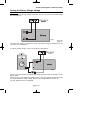
Note: Pos:- STU Adaptor Ch. O/Ps & Pin 11 (ATS) are + 5V active.
Neg:- STU Adaptor Ch. O/Ps & Pin 11 (ATS) are 0V active.
9)
The display will show:Press No until the required option is displayed.
Then press Yes.
STU Adaptor I/P
=Pos
Note: Pos:- RC Reset (Pin 6), FTC (Pin 7), LF (Pin 15) are +5V active.
Neg:- RC Reset (Pin 6), FTC (Pin 7), LF (Pin 15) are 0V active.
STU Adaptor Pin 7
=Power O/P
10)
The display will show:Leave as default when connecting to a STU.
11)
Press Yes. The display will show:Testing the channels should be conducted after the
STU has been configured and enabled.
12)
Press Yes. The display will show:-
Make a STU
Test Call ?
13)
Press Yes. The display will show:-
Test Chan.
Restore ?
Page 47
Test Digicom
Channels ?
is On
GT 600 / 601 Engineer’s Reference Guide
Note: An extra channel (channel 9) is available and will be shown when programming channels or
testing channels. This will only be displayed if the STU has been selected to ON.
Note: STU Adaptor will work in parallel with normal comms device. E.g. MOD+xxx.
When programming as MOD+PID or MOD+SIA then programming for both the Digi channels and
the triggers will be available.
Remote Reset from the STU input (pin 6) can reset the Control Panel provided that the STU Adaptor
option is ON and Remote Reset is ON.
14)
Press Yes. The display will show:-
Chan.
On/Off
123456789
000000000
Pressing the appropriate button will test the
relevant channel. E.g. 3. That channel is now
active showing that a signal is being transmitted.
Pressing 3 again will reset that channel.
Testing is now complete.
15)
To escape press 0. The display will show:-
Program Digicom
Type or Test ?
16)
Press No. The display will show:-
Program Digicom
Delay / Part ?
17)
Press Yes. The display will show:-
Fire Zone Delay
=90 Secs
18)
Press No twice. The display will show:-
Fire Zone Delay
> -- Secs
19)
Enter the number of seconds you require for
the Fire Zone Delay, followed by Yes.
The display will show:-
Page 48
Digi Delay = 00s
Part - Alarm = On
GT 600 / 601 Engineer’s Reference Guide
Digi Delay = _ _s
Part - Alarm = On
20)
Press No twice. The display will show:-
21)
Enter the number of seconds you require for
the Digi Delay in Part Set followed by Yes.
The display will show, for example:-
Digi Delay = 99s
Part - Alarm > On
Press No until the required setting is displayed,
then press Yes. The display will show:-
Program Digicom
Delay / Part ?
22)
With Digi Delay programmed, the alarm transmission to Central Station will be
delayed for the number of seconds programmed.
With Part Alarm programmed to Off there will be no transmission of Alarm,
Alarm B or Alarm Abort if the system is Part Set.
23)
Press No. The display will show:-
Page 49
Program Digicom
Channels ?
GT 600 / 601 Engineer’s Reference Guide
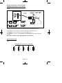
24)
Press Yes. The display will show:-
Ch1 = Off
Ch4 = Off
When programming Digicom Channels Channel 1 is normally Fire, Channel 2 is
normally PA, Channel 3 is normally Alarm (unconfirmed) and Channel 4 is
normally Open/Close.
Channels 5, 6, 7 & 8 will be advised by your Central Station.
Other signals you may require for DD243 are.
Alarm Abort
Zone Exclude
Alarm B (Confirmed)
Channel settings available are.
Off
Zone 24Hr
Gen. Tamper
Alert
Fire
Part-Set
Open/Close
Panic
Alarm
Alarm B
Alarm Abort
Power Fail
Watchdog
Mains Fail
Perimeter
Zone Exclude
Const. Lo-Bat
(Radio)
Radio Lost
(Radio)
Const. Jam.
(Radio)
Any Fault
Any Mask
Power Fail Latch
Global Fault - This ‘Global Fault’ is a fast format communication channel option. With a
channel programmed as ‘Global Fault’ the channel will trigger when one of the
following faults occur: Mains Fail, PSU Fail, Battery Fault, Line Fault, others...
Area 1 to 3 variations of the above will also be displayed.
(Areas 4 to 7, 601 ONLY)
Page 50
GT 600 / 601 Engineer’s Reference Guide
25)
Press No until the required setting is displayed.
26)
Press Yes. The display will show, for example:-
27)
Press No until the required setting is displayed.
28)
Press Yes and repeat as above for the remaining
channels 4 - 9 followed by Yes. The display will
show:-
Ch1 = Fire
Ch4 >Off
Program Digicom
Channels ?
29)
Press No. The display will show:-
Program Digicom
Functions ?
30)
Press Yes. The display will show:-
View Modem Log ?
31)
Press No. The display will show:-
Program Modem
Functions ?
32)
Press Yes. The display will show:-
Access Via
Local PC ?
33)
Press Yes if you require connection to a local PC.
The display will show:-
Remote Access
Otherwise
34)
Press No. The display will show:-
Page 51
Modem Mode
= Off
GT 600 / 601 Engineer’s Reference Guide
Choose from the following settings.
No Return
Communication to the panel is from GardTec Remote via
Patch Lead or PC Modem.
Return PC
The panel will ring the PC back on the number the PC has passed
to the panel.
Return
#1 or #2
The panel will ring back the PC on the #1 or #2 number programmed
into the panel.
Return #1 Only The panel will ring back the PC on the #1 number programmed
into the panel.
Return #2 Only The panel will ring back the PC on the #2number programmed
into the panel.
From Site Only Remote Access will be initialised by the user On-Site.
Off
35)
Modem Functions are disabled.
Press No until the required setting is displayed,
then press Yes. The display will show:-
Double Ring
= Off
This option may be used when when the panel is on a shared line and GardTec
Remote is also used.
36)
Press No until the required setting is displayed,
then press Yes. The display will show:-
Keypad Lock = Off
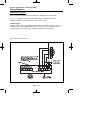
In-Use Text = Off
You may continue to program other Modem options if required. For the purpose of this
Step by Step Guide.
37)
Press 0 (zero). The display will show:-
38)
Press Yes. The display will show:-
Page 52
Program Comms
Functions ?
Comms = Off
GT 600 / 601 Engineer’s Reference Guide
39)
Press No twice. The display will show:-
Comms > On
40)
Press Yes. The display will show, for example:-
Site ID Code
Is Un-Programmed
In the UK the Site ID Code is normally a four digit number, your Central Station
may have supplied you with a six digit number. If this is so, please use the last
four digits.
41)
Press No. The display will show:-
42)
Enter your Site ID Code followed by Yes.
The display will show:-
Site ID Code
________
Phone Number 1
is Un-Programmed
We will be entering two Phone Numbers. If your Central Station has only
supplied you with one Phone Number, please use the same one twice.
43)
Press No. The display will show:-
44)
Enter Phone Number one followed by Yes.
The display will show:-
45)
Press Yes. The display will show:-
Phone Number 2
is Un-Programmed
46)
Press No. The display will show:-
Phone Number 2
_____________
Page 53
Phone Number 1
_____________
Inhibit Display
of New Number ?
GT 600 / 601 Engineer’s Reference Guide
47)
Enter Phone Number 2 followed by Yes.
The display will show:-
48)
Press Yes. The display will show:-
Inhibit Display
of New Number ?
Line Monitor
= Tone + Volts
Settings available for Line Monitor are.
Tone + Volts
The Line Monitor will check the Dial Tone and the Line Voltage
This setting should be used when the control panel is
connected to a dedicated telephone line.
Off
Line Monitor is turned Off
Dial Tone
The Line Monitor will only monitor the Dial Tone. This setting
should only be used on a dedicated telephone line.
Line Volts
The Line Monitor will monitor the Line Voltage. This setting
should be used when the control panel is connected to a
telephone line that has other telephone equipment on it
(shared line).
49)
Press No until the required setting is displayed
then press Yes. The display will show:-
Line Security
= High
Settings available for Line Security are:High
The Line Voltage is monitored at a High Level. This setting should
be used on dedicated lines only.
Low
The Line Voltage is monitored at a Low Level. This setting should
be used when the control panel is sharing the line with other
telephone equipment.
Page 54
GT 600 / 601 Engineer’s Reference Guide
50)
Press No until the required setting is displayed
then press Yes. The display will show:-
Channel 1 2 3 4 5 6 7 8
R/Rep = 0 0 0 1 0 0 0 0
This option determines what Digi Channels will send a Restore Signal to Central
Station when the system is Reset. Most Central Stations will require a Restore
Report for all channels.
51)
Press No. The display will show:-
Channel 1 2 3 4 5 6 7 8
R/Rep = _ _ _ _ _ _ _ _
52)
Enter eight ones so the display shows:-
Channel 1 2 3 4 5 6 7 8
R/Rep = 1 1 1 1 1 1 1 1
53)
Press Yes. The display will show:-
Open/Close
Channel/s = 4
Channel 4 normally needs an inversion of the signal that is sent to Central
Station. By having 4 as the setting for this option channel 4 will be inverted. If
you have reports from the Central Station that the Open/Close channels are the
wrong way around proceed as follows to remove the inversion on the control
panel.
54)
If you do not need to change this option, press
Yes and jump to Step 56.
Or
To change the setting. Press No.
The display will show:-
55)
Press 0 followed by Yes. The display will show:-
Open/Close
Channel/s > _ _
Program Advanced
Functions ?
Note: For EN requirements, a Test Call MUST be sent to the Central Station once
every 24 Hrs. This can be found under advanced function, under Test Call Time.
Page 55
GT 600 / 601 Engineer’s Reference Guide
You may continue to program other Advanced options if required. For the purpose of
this Step by Step Guide.
56)
Press 0 (zero) five times. The Display will show:-
Page 56
01 Jan
00: 00: 01
GT 600 / 601 Engineer’s Reference Guide
Programming Linefault Modes
1)
Enter into Engineer Mode
To do this follow Steps 1 to 4 on page 11
With the display showing:-
Program . . . .
Zones ?
___
2)
Press No six times. The display will show:-
Program . . . .
___
Linefault Modes ?
3)
Press Yes. The display will show:-
Program Linefault
Sounders ?
4)
Press Yes. The display will show:-
Linefault Sounders
= ON if Un-Set
5)
Press No until the required setting is displayed
then press Yes. The display will show:-
Program Linefault
Sounders ?
6)
Press No. The display will show:-
Program Lineflt
Mode in Exit ?
7)
Press Yes. The display will show:-
Lineflt Mode . . .
= Detect in Exit
8)
Press No until the display shows the required
setting then press Yes. The display will show:-
Page 57
Program Lineflt
Mode in Exit ?
GT 600 / 601 Engineer’s Reference Guide
9)
Press No. The display will show:-
Program Lineflt
Log Mode ?
10)
Press Yes. The display will show:-
Lineflt Log
: Limited
Note: Line Fault is defaulted to Limited and may not be changed.
This limit is set to 3 events.
11)
Press Yes. The display will show:-
Program Lineflt
Log Mode ?
12)
Press No. The display will show:-
Program Lineflt
Detect Time ?
13)
Press Yes. The display will show:-
Detect
= 30 Secs
With Detect programmed as 00 Linefault detection is instant or it may be delayed
if required.
14)
Press No twice. The display will show:-
15)
Enter the time you require (in seconds) followed
by Yes. The display will show:-
16)
This concludes the programming for
Linefault Sounders. Press 0 (zero) to return to:-
Detect
> _ _ Secs
Program Lineflt
Detect Time ?
Program . . . .
___
Linefault Modes ?
Or
Press 0 (zero) until the display shows:-
Page 58
01 Jan
00: 00: 01
GT 600 / 601 Engineer’s Reference Guide
Programming Panic / Duress
Note: Duress is defaulted to Off and cannot be changed. Duress 7 is now no
longer available.
You should also check current legislation if Panic & Duress signals are allowed for the
grade of system that you are fitting.
1)
Enter into Engineer Mode
To do this follow Steps 1 to 4 on page 11
With the display showing:-
Program . . . .
Zones ?
___
___
2)
Press No seven times. The display will show:-
Program . . . .
Panic / Duress ?
3)
Press Yes. The display will show:-
PA = Bells Only
= Non-Testable
It should be noted that with PA = Bells Only no PA signals will be sent to Central
Station.
Available setting for PA are
Bells Only
Activating a Panic will only sound the Bells.
Bells Always
Activating a Panic will Sound the Bells and send a signal
to Central Station provided that a Digi Channel is
programmed as Panic.
Silent Always
Activating a Panic will only send a signal to Central Station
providing that a Digi Channel has been programmed as
Panic.
Bells if LFlt
As Silent Always but will revert to Bells if a Linefault is
present.
Page 59
GT 600 / 601 Engineer’s Reference Guide
4)
Press No until the required setting is displayed
then press Yes. The display will show:-
5)
Press No until the required setting is displayed
then press Yes. The display will show:-
PA = Bells Only
> Non-Testable
Duress : Off
Note: Duress is defaulted to Off and may not be changed.
6)
Press Yes. The display will show:-
7)
Press 0 (zero) until the display shows:-
Page 60
Program . . . .
Panic / Duress
01 Jan
___
00: 00: 01
GT 600 / 601 Engineer’s Reference Guide
Programming PGM2 / 3 / Timers
PGM2 refers to the PGM2 terminal on the control panel PCB situated near to the
speaker terminals.
PGM3 Refers to the Strobe terminal, if this is not used for the Strobe (for example if a
NovActive Bell Box is used) it may be re-programmed for other uses.
One Timer is also available. It should be noted that the times programmed will operate
seven days per week, you are not able to program separate time for weekends etc.
1)
Enter into Engineer Mode
To do this follow Steps 1 to 4 on page 11
With the display showing:-
Program . . . .
Zones ?
2)
Press No eight times. The display will show:-
3)
Press Yes. The display will show:-
Program PGM2 / 3
Operating Modes ?
4)
Press Yes. The display will show:-
PGM2 O/P
=Bell
Options available for PGM2 / 3 are.
Bell
Alert
Any-Fire
Any-Panic
Alarm
AlarmB
Alm Abort
O/C Cleaner
Cleaner Set
Gen.Tamper
Zone-24Hr
Part-Set
(Unconfirmed)
(Confirmed)
(Alarm Abort)
Page 61
___
Program . . . .
___
PGM2 / 3 / Timers ?
=+V
GT 600 / 601 Engineer’s Reference Guide
contStrobe
Latch Any
Any Set
Power-Fail
Power OK
Const. LoBat
(Radio Low Battery)
Radio Lost
(Lost Radio Detector etc)
Const. Jamm.
(Radio Signal Jamming)
Any Fault
Any Mask
Watchdog
Mains-Fail
Any-Digi
Status
Perimeter
Zon Exclude
Custom 1- 8
Off
Timed 1 - 3
Any-Closed
Pulse Off
Pulse On
After Alarm
Walktest
Pulse Set
Int. Sounder
E/E
Area variants of the above will also be displayed.
(Areas 4 to 7, 601 ONLY)
5)
Press No. The display will show:Choose from one of the options displayed. E.g. If 5
is selected PGM2 will operate when ANY detector
is triggered.
(Choose 1 - 7 for Areas, 8 All, 9 Any, 601 ONLY)
6)
The display will show:-
7)
Press No until the required setting is displayed,
then press Yes. The display will show, for example:-
Choose 1=A1 2=A2
3=A3 4=All 5=Any
PGM2 O/P
>Bell
=+V
PGM2 O/P
=Bell
>+V
With the PGM2 programmed as Bell the output will operate with the Bell when this is
set as +V. With this set as -V the output will be inverted e.g On, turning Off with the
Bell.
Page 62
GT 600 / 601 Engineer’s Reference Guide
8)
Press No until the required setting is displayed.
Then press Yes. The display will show:-
PGM3 O/P
=Strobe
=+V
9)
Repeat steps 5 - 8 for PGM3 O/P.
The display will show:-
10)
Press No. The display will show:-
Program PGM2 / 3
Timer 1 ON Time ?
11)
Press Yes. The display will show:-
Timer 1 ON Time
= 00:00 Hrs
12)
Press No twice. The display will will show:-
Timer 1 ON Time
> _ _ : 00 Hrs
13)
Enter the On Time hours, followed by Yes.
The display will show:-
14)
Press No. The display will show:-
Timer 1 ON Time
= 10:>_ _ Hrs
15)
Enter the On Time minutes, followed by Yes.
The display will show:-
Program PGM2 / 3
Timer 1 ON Time ?
16)
Press No. The display will show:Repeat for Timer 1 OFF Time.
Program PGM2 / 3
Timer 1 OFF Time ?
17)
Press Yes. The display will show:-
Program PGM2/3
Timer 1 OFF Time?
Page 63
Program PGM2 / 3
Operating Modes ?
Timer 1 ON
= 10:>00 Hrs
Time
GT 600 / 601 Engineer’s Reference Guide
18)
Press No. The display will show:-
19)
Repeat the sequence for Timers 2 & 3 On & Off Times.
20)
This concludes the programming for PGM2/3/Timers.
21)
Press 0 (zero) to return to:-
Program PGM2/3
Timer 2 ON Time ?
Program . . . .
___
PGM2 / 3 / Timers ?
or
Press 0 (zero) until the display shows:-
Page 64
01 Jan
00: 00: 01
GT 600 / 601 Engineer’s Reference Guide
Programming Reset Modes
1)
Enter into Engineer Mode
To do this follow Steps 1 to 4 on page 11
With the display showing:-
2)
Press No nine times. The display will show:-
3)
Press Yes. The display will show:-
4)
Press No twice, then enter the Mains Fail Delay
time you require.Then press Yes.
The display will show:This is Area 1 Reset Mode. Repeat for all
Areas used.
Program . . . .
Zones ?
___
Program . . . .
Reset / Mains ?
___
Mains Fail Delay
=20m
Alarm1 Reset
= Master
Note: Default is set at 20 minutes. Will delay the communication of Mains Fail.
5)
Press No until the required setting is displayed,
then press Yes. The display will show:-
Tamper Reset
= Eng. +Anti
6)
Press No until the required setting is displayed,
then press Yes. The display will show:-
Alrm Restore = Off
Abort Time = 60s
When Alarm Restore is turned On, the Digi channels programmed with Restore On will
be Restored when the system is unset, rather than when the system is Reset.
7)
Press No until the required setting is displayed,
then press Yes. The display will show, for example:-
Alrm Restore = On
Abort Time > 60s
8)
Press No until the required abort time is set followed
by Yes. (0-180 seconds in increments of 20
seconds). The display will show:-
Program . . . .
Reset / Mains ?
Page 65
___
GT 600 / 601 Engineer’s Reference Guide
9)
This concludes the programming for Reset Modes.
10)
Press 0 (zero) until the display shows:01 Jan
Page 66
00: 00: 01
GT 600 / 601 Engineer’s Reference Guide
Programming Sounder Levels
1)
Enter into Engineer Mode
To do this follow Steps 1 to 4 on page 11
With the display showing:-
Program . . . .
Zones ?
___
2)
Press No ten times. The display will show:-
Program . . . .
___
Sounder Levels ?
3)
Press Yes. The display will show:-
Program Sounder
Chime Level ?
4)
Press Yes. The display will show:-
Chime Level . . . . .
= 05
5)
Press No twice. The display will show:-
Chime Level . . . . .
=__
6)
Enter a value 1 to 9 (1=Low 9=High) followed by
Yes. The display will show:-
7)
Press No. The display will show:-
Program Sounder
Ent / Exit Level ?
8)
Press Yes. The display will show:-
Ent / Exit Level
= 05
Page 67
Program Sounder
Chime Level ?
GT 600 / 601 Engineer’s Reference Guide
9)
Press No twice. The display will show:-
10)
Enter a value 1 to 9 (1= Low 9 = High) followed by
Yes. The display will show:-
11)
Press No. The display will show:-
Program Sounder
Key Beep Level ?
12)
Press Yes. The display will show:-
Key Beep Level . .
= 05
13)
Press No twice. The display will show:-
Key Beep Level . .
=__
14)
Enter a value 1 to 9 (1 = Low 9 = High) followed by
Yes. The display will show:-
Program Sounder
Key Beep Level ?
15)
This concludes the program Sounder Levels
press 0 (zero) to move back to:-
Program . . . .
Sounder Levels ?
16)
Then Press 0 until the display shows:-
Page 68
Ent / Exit Level
=__
Program Sounder
Ent / Exit Level ?
01 Jan
___
00: 00: 01
GT 600 / 601 Engineer’s Reference Guide
Programming PGM1 / Xp / Custom
PGM1 is located on the control panel PCB.
Up to 8 custom outputs may be programmed on to PGM 1 to 3. A custom output may
be used so that the output can follow a zone or a user code.
1)
Enter into Engineer Mode
To do this follow Steps 1 to 4 on page 11
With the display showing:-
2)
Press No eleven times. The display will show:-
3)
Press Yes. The display will show:-
Program . . . .
Zones ?
___
Program . . . .
___
PGM1 / Xp / Custom ?
PGM1 O/P
= Pulse Off
=+V
The options available for PGM1 are shown on page 61.
4)
Press No. the display will show:Choose from one of the options displayed. E.g. If 5
is selected PGM1 will operate when ANY detector
is triggered.
(Choose 1 - 7 for Areas, 8 All, 9 Any, 601 ONLY)
Choose 1=A1 2=A2
3=A3 4=All 5=Any
5)
The display will show:-
PGM1 O/P
>Pulse Off
=+V
6)
Press No until the required setting is displayed
then press Yes. The display will show:-
PGM1 O/P
=Pulse Off
>+V
With the PGM1 programmed as Bell, the output will operate with the Bell when this is
set as +V. With this set as -V the output will be inverted, e.g On, turning Off with the
Bell.
7)
Press No until the required setting is displayed
then press Yes. The display will show:-
Page 69
Expander 1
=Off
O/P 1
=+V
GT 600 / 601 Engineer’s Reference Guide
8)
Press No. the display will show:Choose from one of the options displayed.
9)
The display will show:-
10)
Press No until the required setting is displayed
then press Yes. The display will show:-
Choose 1=A1 2=A2
3=A3 4=All 5=Any
Expander 1 O/P 1
>Off
=+V
Expander 1
=Off
O/P 1
>+V
With Expander 1 / Output 1 programmed as Bell, the output will operate with the Bell
when this is set as +V. With this set as -V the output will be inverted, e.g On, turning
Off with the Bell.
11)
Repeat the sequence for Expanders O/P 2 - 4 if required.
12)
With the display showing:Press Yes.
Expander 4
=Off
13)
The display will show:Press No to change the Cus 1 to Zone, Code or
Group as required to follow. Press Yes.
Cus 1 = Zone
=Day = Fol+
#=000
t=00
14)
The display will show:-
Cus 1 = Zone
=Day = Fol+
#>000
t=00
15)
Press No. The display will show:-
Cus 1 = Zone
=Day = Fol+
#>_ _ _
t=00
Page 70
O/P 4
=+V
GT 600 / 601 Engineer’s Reference Guide
16)
Enter the Zone Number or Customer Number
that you wish the output to follow. Then press
Yes. The display will show for example:-
Cus 1 = Zone
>Day = Fol+
#=009
t=00
Cus 1 = Zone
=Day > Fol+
#=009
t=00
Cus 1 = Zone
+Day = Fol+
#>009
t>00
17)
Press No to select when you want the output to
operate, followed by Yes. The display will show:-
18)
Press No until the mode you require is displayed,
then press Yes. The display will show:-
19)
Press No. The display will show:-
Cus 1 = Zone
+Day = Fol+
#>009
t> _ _
20)
Enter the time required, followed by Yes.
The display will show:-
Cus 2 = Zone
=Day = Fol+
#=000
t=00
The t = 00 setting only applies to Fol+
Fol- Pul+ Pul21)
22)
Repeat Steps 13 to 21 until all the Custom
Outputs you require have been programmed.
When you have programmed Custom 8 the
display will show:-
Press 0 (zero) until the display shows:-
Page 71
Program . . . .
___
PGM1 / Xp /Custom ?
01 Jan
00: 00: 01
GT 600 / 601 Engineer’s Reference Guide
Programming Engineer Code
1)
Enter into Engineer Mode
To do this follow Steps 1 to 4 on page 11
With the display showing:-
Program . . . .
Zones ?
___
___
2)
Press No twelve times. The display will show:-
Program . . . .
Engineer Code ?
3)
Press Yes. The display will show:-
Now Enter Code . .
_ _ _ _ _ _ Then YES
4)
Enter your New Engineer Code (4, 5 or six digits)
followed by Yes. The display will show:-
Code = Unlocked
Be careful if you lock your code in. If the code is forgotten you may have to
return the control panel to the factory to have it unlocked, this will be a
chargeable service.
5)
6)
Press No until the required setting is displayed,
then press Yes. The display will show:-
Program . . . .
Engineer Code ?
___
This concludes the Program Engineer Code.
Press 0 (zero) until the display shows:01 Jan
Page 72
00: 00: 01
GT 600 / 601 Engineer’s Reference Guide
Programming Service
Within this section you will program the Service Timer. The Service Timer has the
ability to Lock a user out of the system when the Service Time expires. Trading
Standards may take action if a Lockout occurs and no Service Contract exists. Please
use with care.
1)
Enter into Engineer Mode
To do this follow Steps 1 to 4 on page 11
With the display showing:-
Program . . . .
Zones ?
___
Press No thirteen times. The display will show:-
Program . . . .
Service / PTM ?
___
3)
Press Yes. The display will show:-
Gardtec60x
ENx 50Hz
4)
Press Yes. The display will show:-
Save Panel NVM
to PTM ?
5)
Press Yes if you require to save to PTM.
2)
Version
xx-xx
Ok?
Otherwise
6)
Press No. The display will show:-
7)
Press Yes if you require to load from the PTM.
Load Panel NVM
from PTM ?
Otherwise
Service Timer
= Off
8)
Press No. The display will show:-
Note:
To transfer data to and from the PTM connect the cable to CON4.
(Part no 1CB 6049)
Note:
When data transfer is in progress, the LED on the PTM will flash rapidly.
Page 73
GT 600 / 601 Engineer’s Reference Guide
9)
Press No twice. The display will show:-
Service Timer
> On
10)
Press Yes. The display will show:-
Next Service due
in 00 Weeks
11)
Press No twice. The display will show:-
Next Service due
in _ _ Weeks
12)
Enter the number of weeks you require to the
next service, then press Yes.
The display will show:Note:
Service Tel. No.
is Un-Programmed
The system will start to warn the end
user that the Service is due two weeks
before the time expires.
13)
Press No. The display will show:-
14)
Enter the Telephone Number you wish your
customer to dial for service, followed by Yes.
The display will show:With Lock - Out turned On the system will
Lock the users out when the Service Time
expires.
With Lock - Out turned Off the system will
continue to warn of Service until the Service
Timer is reset.
Page 74
Service Tel. No.
_____________
! ! ! LOCK - OUT ! ! !
= On
GT 600 / 601 Engineer’s Reference Guide
15)
Press No until the required setting is displayed
then press Yes. The display will show:-
Engineer Mode
= Constant
With Engineer Mode programmed as Constant
the panel will remain in Engineer Mode until
the Engineer exits.
With Engineer Mode programmed as timed the
panel will jump out of Engineer Mode after 1 hour
if all the Tampers are clear. This prevents the
Engineer accidentally leaving the panel in
Engineer Mode.
16)
Press No until the required setting is displayed,
then press Yes. The display will show:-
17)
This concludes the Program Service.
Press 0 (zero) until the display shows:-
Page 75
Program . . . .
Service / PTM ?
01 Jan
___
00: 00: 01
GT 600 / 601 Engineer’s Reference Guide
Programming Custom Screens
1)
Enter into Engineer Mode
To do this follow Steps 1 to 4 on page 11
With the display showing:-
Program . . . .
Zones ?
___
2)
Press No fourteen times. The display will show:-
Program . . . .
___
Custom Screens ?
3)
Press Yes. The display will show:-
LCD Status
: None
Note: The LCD Status is defaulted to None and may not be changed. The display will only show the
Set / Unset status of the system for ten seconds after a Set or Unset.
4)
Press Yes. The display will show:-
LED Status
= Off
The LED Status refers to the LED in the G-Tag ‘E’ or ‘I’
reader. Choose from:Off
The reader LED will only show for
ten seconds after a Set / Unset
On
5)
The reader LED will always be active.
Press No until the required setting is displayed.
Then press Yes. The display will show:-
Custom Display
=Off
Note: If set to On, the custom text will be displayed when the system is Un-Set. This is only
applicable if the Control Panel has been programmed to BS standard.
6)
Press No until the required setting is displayed.
Then press Yes. The display will show:-
Program Text ?
Press 0 three times to return to the date/time display (EN standard)
Or
If you wish to change the Custom Display (BS only), press Yes then No. You
may now enter up to 32 characters. (Refer to the character map on page 14).
Page 76
GT 600 / 601 Engineer’s Reference Guide
7)
As you press Yes for the last character the display
will change to:-
Program . . . .
___
Custom Screens ?
This concludes the Custom Screens.
Press 0 (zero) twice to return to:-
01 Jan
00: 00: 01
Programming Diagnostics / Log
The GT 600 / 601 control panels have some limited diagnostic features available to the
engineer.
To access these proceed as follows.
1)
Enter into Engineer Mode
To do this follow Steps 1 to 4 on page 11
With the display showing:-
Program . . . .
Zones ?
___
2)
Press No fifteen times. The display will show:-
Program . . . .
___
Diagnostics / Log ?
3)
Press Yes. The display will show:-
List
Event Log ?
4)
Press Yes if you wish to view the Event Log
The display will show, for example:-
Eng. Code
01 Jan 01:18:12
This is the last event in the Log
Use the No key to move backward in the Log
Use the Yes key to move forward in the Log
5)
When you have finished viewing the Log press
0 (zero). The display will show:-
Page 77
Program . . . .
___
Diagnostics / Log ?
GT 600 / 601 Engineer’s Reference Guide
6)
Press Yes. The display will show:-
List
Event Log ?
7)
Press No. The display will show:-
Change / List
Diagnostics ?
8)
Press Yes. The display will show:-
PSU . . .
Diagnostics ?
9)
Press Yes. The display will show:-
PSU Test Time
= 01 Hrs
A PSU/Battery test will be carried out at the time
interval set here and each time you leave Engineer
Mode. This may be turned Off by setting the Time
interval to 0 (zero).
10)
Press No twice. The display will show:-
11)
Enter the time you require (in hours) followed by
Yes. The display will show:-
12)
Press Yes. The display will show:-
PSU Test Time
= _ _ Hrs
Change / List
Test Limits ?
Aux. Vmax = 14.0
Aux. Vmin = 11.8.
In this example any voltage over 14V or below
11.8V will create a warning when the PSU test
is performed by the system.
13)
To change these limits. Press No until the required
setting for V.Max is displayed, then press Yes.
The display will show, for example:-
Page 78
Aux. VMax = 14.0V
Aux. VMin > 11.8V
GT 600 / 601 Engineer’s Reference Guide
14)
15)
16)
17)
18)
Press No until the setting required for V.Min is
displayed, then press Yes.
The display will show:-
Press No until the required setting for On-Charge
Volts max (Battery) is displayed, then press Yes.
The display will show:-
Press No until the required setting for On-Charge
Volts min (Battery) is displayed then press Yes.
The display will show:-
Press No until the required setting for Off-Charge
Volts max (Battery) is displayed, then press Yes.
The display will show:-
Press No until the required setting for Off-Charge
Volts min (Battery) is displayed, then press Yes.
The display will show:-
On - Chg. max = 14.0
On - Chg. min = 11.8
On - Chg. max = 14.0
On - Chg. min > 11.8
Off - Chg. max = 14.0
Off - Chg. min = 11.8
Off - Chg. max = 14.0
Off - Chg. min > 11.8
PSU . . .
Diagnostics ?
19)
Press Yes. The display will show:-
PSU Test Time
= 01 Hrs
20)
Press Yes. The display will show:-
Change / List
Test Limits ?
Page 79
GT 600 / 601 Engineer’s Reference Guide
The readings given from this point on are intended as Indicator Only and should
be confirmed with a calibrated Test Meter.
21)
Press No. The display will show, for example:-
Aux. Volts
13.6V
22)
Press Yes. The display will show, for example:-
Battery Volts
On Charge 13.6V
23)
Press Yes. The display will show, for example:The backlight will dim at this point.
Battery Volts
Off Charge 12.9V
24)
Press Yes. The display will show, for example:-
Aux. Volts
13.6V
25)
This concludes the Program Diagnostics.
Press 0 (zero) until the display shows:-
Page 80
01 Jan
00: 00: 01
GT 600 / 601 Engineer’s Reference Guide
Programming Alarm Confirm
This section is used to program options that are relevant to DD243. Before
programming these options please take time to read the following notes that will help in
your understanding of DD243 - BS8243
All communications systems that require a Police URN will need to conform to DD243.
These notes intended as a guide only and should be read in conjunction with the
relevant standards relating to the alarm system giving particular attention to
EN50131-1and DD243. These may be obtained from the British Standards Institute.
DD243 options available are.
Confirm Time Window (default = 60)
This time window may be programmed between 1 and 120 minutes. To comply the
required time should be between 30 and 60 minutes.
Confirm on Entry (default = On)
This option may be programmed to On or Off. If Confirm on Entry = Off then confirmed
alarms to central station are disabled if the entry timer is started. If ACE or G-Tag is
used then it is permissible to set this option to On.
Sounder Mode (default = Unconfirmed)
This option controls the system speakers fitted, options are confirmed or un-confirmed.
If Sounder Trigger = Confirmed then internal sounder will only trigger with a confirmed
alarm.
If Sounder Trigger = Unconfirmed then internal sounders will trigger with un-confirmed
alarms.
This feature is not mandatory for DD243
Reset Mode (default = Any)
Choose from Any or Normal.
If Unconfirm = Any then any code can be used to reset an un-confirmed alarm.
If Unconfirm = Normal then the programmed reset mode for alarm will still be required
i.e. if alarm reset has been programmed as engineer and Unconfirm reset is Normal
then an engineer reset will be required for Un-confirmed alarms.
Confirm Secondary Time Window (default = 60 minutes)
This time window may be programmed between 1 and 120 minutes we would suggest
a time between 30 and 60 minutes but should typically be the same time as the
confirm time window. This option affects zones that have been allocated as secondary
zones only. For functionality please refer to Secondary Zones Below.
Page 81
GT 600 / 601 Engineer’s Reference Guide
ET (Exit Terminator) Mode (default = Set)
If ET Mode = Set then the exit terminator zone will terminate the exit procedure.
If ET Mode = Door Lock and the ET zone (door lock) is operated on entry then all
confirmed alarms will be disabled.
Bell Mode (default = Unconfirmed)
This option controls the bells fitted to the system, options are confirmed or unconfirmed.
If Bell Trigger = Confirmed then Bell will only trigger with a confirmed alarm.
If Bell Trigger = Unconfirmed then Bell will trigger with un-confirmed alarms.
This feature is not mandatory for DD243
Strobe Mode (default = Unconfirmed)
This option controls the Strobe(s) fitted to the system, options are confirmed or unconfirmed.
If Strobe Trigger = Confirmed then Strobe will only trigger with a confirmed alarm.
If Strobe Trigger = Unconfirmed then Strobe will trigger with un-confirmed alarms.
This gives the ability to show to the keyholder from outside the premises that a
previously unconfirmed alarm has is now confirmed.
This feature is not mandatory for DD243
Confirmed Start Delay (default = 000m)
May be programmed between 0 & 120 minutes (default 0).
If programmed to anything other than 0 the panel cannot send confirmed signals until
the time programmed has expired. This time starts when the system has set and will
prevent confirmed alarms being generated in situations when a person has been
accidentally locked in the building.
This feature is not mandatory for DD243
Ace Low Battery (default = On)
Options are On or Off. This option allows for the use of new control panel boards with
V5.1 or later software to be used with earlier keypads. If older non DD243 compliant
type keypads are used with V5.1 or later this option should programmed to Off. It is a
requirement of DD243 2002 that when using ACE Low Battery is reported to the end
user if the system is set using ACE.
See A.1 DD243 Portable ACE used for setting and unsetting.
Secondary Zones
The Program Part / Test /Chime option has now been renamed to Program Zone
Attributes. Within this section you are able to allocate zones as Secondary Zones.
Secondary type zones would be used for detectors that may be deemed as having an
over sensitive nature, this will stop unwanted user call-outs. Zones that are entered as
Secondary will follow the chain of events below.
Comms Restore
With Comms Restore turned on any outstanding alarm channels will be restored at the
end of the Confirm Time Window.
This feature is mandatory for DD243
Page 82
GT 600 / 601 Engineer’s Reference Guide
During a set period triggering a Secondary Zone will start the Secondary Time
Window. This will be logged but no further action is taken. If the second zone to alarm
during the same set period is also a Secondary Zone then it will be logged and the
Secondary Time Window will be restarted.
If the time set within the Secondary Time Window is still running and a zone that is not
allocated as a Secondary Zone is triggered the event will be logged an Alarm A (unconfirmed) and Alarm B (confirmed) will be transmitted.
This feature is not mandatory for DD243
Perimeter Zones
Within the Program Zone Attribute section you are able to allocate zones as Perimeter.
Zones that are entered as Perimeter will follow the chain of events below.
When activated an unconfirmed alarm will be transmitted to the central station. An
output or digi channel may be programmed as perimeter (or if using Point ID a new
signal type of perimeter will be sent). This will allow central station to inform the
keyholder that an unconfirmed alarm has been received and is a perimeter type device
i.e window backdoor etc. etc. This feature is not mandatory for DD243.
Scenarios Relating to DD234.
Sounder / Bell Considerations
Please note careful consideration should be given when programming Confirm
Sounder and Confirm Bell Modes. If both are programmed for confirmed and any of the
above scenarios occur no local sounders will activate.
Other DD243 Notes to Consider
When a system auto re-arms with a zone in fault condition The GardTec control panel
will omit the zone concerned. A signal should be sent to the central station indicating
that a detector(s) has (have) been isolated. To achieve this a Digi channel should be
programmed as Zone Exclude, this will automatically send the required signal as the
detector is omitted.
Output Option (Status)
This option has three operating modes and is intended to provide a visual indication of
the system status.
System Set
Output On for 10 seconds
System Unset
Output On for 1s Output Off for 1s for a 10 second
period
Confirmed Alarm
Output On for 3 seconds Output Off for 1s until
system reset.
It is envisaged that this status output would be fitted to an indicator (i.e. LED) that can
be seen from outside the premises.
Page 83
GT 600 / 601 Engineer’s Reference Guide
1)
Enter into Engineer Mode
To do this follow Steps 1 to 4 on page 11
With the display showing:-
Program . . . .
Zones ?
___
___
2)
Press No sixteen times. The display will show:-
Program . . . .
Alarm Confirm ?
3)
Press Yes. The display will show:-
Program Confirm
Window Time ?
4)
Press Yes. The display will show:-
Confirm Window
= 060m
5)
Press No twice. The display will show:-
Confirm Window
> _ _ _m
6)
Enter the time you require, followed by Yes.
The time MUST be between 30 & 60 minutes.
Page 84
GT 600 / 601 Engineer’s Reference Guide
7)
The display will show:-
Program Confirm
Time Window ?
8)
Press No. The display will show:-
Program Confirm
On Entry ?
9)
Press Yes. The display will show:-
Confirm on Entry
= On
Confirm on Entry may be On only if you are
using an ACE device to Unset the system.
10)
Press No until the required setting is displayed,
then press Yes. The display will show:-
Program Confirm
On Entry ?
11)
Press No. The display will show:-
Program Confirm
Sounder Mode ?
12)
Press Yes. The display will show:-
Sounder Trigger
= Unconfirmed
The term Sounder relates to the system speaker(s)
13)
Press No until the required setting is displayed,
then press Yes. The display will show:-
Program Confirm
Sounder Mode ?
14)
Press No. The display will show:-
Program Confirm
Reset Mode ?
15)
Press Yes. The display will show:-
Unconfirm Reset
= Any
Page 85
GT 600 / 601 Engineer’s Reference Guide
16)
Press No until the required setting is displayed,
then press Yes. The display will show:-
Program Confirm
Reset Mode ?
17)
Press No. The display will show:-
Program Confirm
Secondary Time ?
18)
Press Yes. The display will show:-
Secondary Window
= 060m
19)
Press No twice. The display will show:-
Secondary Window
= _ _ _m
20)
Enter the time required then press Yes.
The display will show:-
21)
Press No. The display will show:-
Program Confirm
ET Mode ?
22)
Press Yes. The display will show:-
ET Mode
= Set Only
23)
Press No until the required setting is displayed,
then press Yes. The display will show:-
24)
Press No. The display will show:-
Page 86
Program Confirm
Secondary Time ?
Program Confirm
ET Mode ?
Program Confirm
Bell Mode ?
GT 600 / 601 Engineer’s Reference Guide
25)
Press Yes. The display will show:-
26)
Press No until the required setting is displayed,
then press Yes. The display will show:-
27)
Press No. The display will show:-
28)
Press Yes. The display will show:-
29)
Press No until the required setting is displayed,
then press Yes. The display will show:-
Bell Trigger
= Unconfirmed
Program Confirm
Bell Mode ?
Program Confirm
Strobe Mode ?
Strobe Trigger
= Unconfirmed
Program Confirm
Strobe Mode ?
30)
Press No. The display will show:-
Program Confirm
Start Delay ?
31)
Press Yes. The display will show:-
Start Delay
= 000m
32)
Press No twice. The display will show:-
Start Delay
> _ _ _m
33)
Enter the time required, followed by Yes.
The display will show:-
Page 87
Program Confirm
Start Delay ?
GT 600 / 601 Engineer’s Reference Guide
34)
Press No. The display will show:-
Program Confirm ?
ACE Bat. Monitor
35)
Press Yes. The display will show:-
ACE Bat. Monitor
=On
36)
Press No until the required setting is displayed,
then press Yes. The display will show:-
Program Confirm ?
ACE Bat. Monitor
37)
Press No. The display will show:-
Program Confirm
Comms. Restore ?
38)
Press Yes. The display will show:-
Comms. Restore
= On
39)
Press No until the required setting is displayed,
then press Yes. The display will show:-
Program Confirm
Comms. Restore ?
40)
Press No. The display will show:-
Program Confirm
Keypad Opening ?
41)
Press Yes. The display will show:-
Options available are:
Always On
*Off in E/E
Keypad Opening
= Always On
Keypad(s) are always On
Keypad(s) not available during
Entry/Exit. ACE must be used.
*Off in E/E/Alm
Keypads not available during
Entry/Exit or if E/E has gone
through to an alarm
*One of these options will be required by your inspectorate.
42)
Press No until the required setting is displayed,
then press Yes. The display will show:-
43)
This concludes the Program Alarm Confirm
Press 0 (zero) three times to return to:-
Page 88
Program Confirm
Keypad Opening ?
01 Jan
00: 00: 01
GT 600 / 601 Engineer’s Reference Guide
NovActive Description & Programming
NovActive utilises a four core bus to the NovActive sounders that are fitted to the
system. This allows each individual Bell to to programmed and also gives access to
unique Diagnostic Features that allow the individual NovActive sounders to be
diagnosed from either the control panel or via GardTec Remote PC Software. GardTec
Remote may be used from either a remote location via a Modem or on-site via a
GardTec Modem Patch Lead.
To program the NovActive sounder(s) please follow the instructions below.
Wiring of the NovActive should be carried out in conjunction with the instructions
supplied with the unit.
1)
Enter into Engineer Mode
To do this follow Steps 1 to 4 on page 11
With the display showing:-
Program . . . .
Zones ?
2)
Press No three times. The display will show:-
3)
Press Yes. The display will show:-
4)
Press Yes. The display will show:-
NovActive = Off
5)
Press No twice. The display will show:-
NovActive > On
6)
Press Yes. The display will show:-
Page 89
___
Program . . . .
___
Bells / Sounders ?
Program Bell
Type ?
Select NovActive
1-8
GT 600 / 601 Engineer’s Reference Guide
7)
Press the number of the NovActive you wish to
program. The display will show:-
8)
Press No twice to turn NovActive 1 On. Then press
Yes. The display will show:-
NovA1 = Off LEDS = 0
Confirm = Off
NovA1 = On LEDS > 0
Confirm = Off
To program the LED pattern press No until the
setting required is displayed.
Choose from.
0 = Alternating LEDs
1 = 1 Static LED
2 = 2 Pulsing LEDs
3 = No LEDs
9)
When you are happy with your selection press
Yes. The display will show:-
NovA1 = On LEDS > 0
Confirm > Off
To program the Setting Confirmation press No
until the required setting is displayed, then press
Yes. The display will show:10)
NovA1 A=1
PA=0 Alm=0
Tmp=0
NovA1 A=1
PA>3 Alm=0
Tmp=0
Press the No key to select which Area(s) the
NovaActive will respond to. Then press Yes
The display will show:-
11)
To program the sound, press No until the required setting is displayed,
then press Yes.
12)
Repeat for Alm, Tmp until the required settings are
displayed.Then press Yes. The display will show:-
13)
Press No. The display will show:-
Page 90
NovA1 Text =
NovActive1
NovA1 Text
-
=>
GT 600 / 601 Engineer’s Reference Guide
14)
Enter the text required. E.g. Front Wall Bell. Then
press Yes. The display will show:-
Select NovActive
1-8
Note: See Page 14 for entering text instructions.
You should now repeat until all the NovaActives on the system have been
programmed.
15)
When you have finished programming all the
NovaActives press 0 until the display shows:-
Page 91
01 Jan
00: 00: 01
GT 600 / 601 Engineer’s Reference Guide
Programming Point ID & SIA Protocol
For the purpose of programming PID / SIA, it is assumed that the STU Adaptor
has been left in the OFF state.
1)
Enter into Engineer Mode
To do this follow Steps 1 to 4 on page 11
With the display showing:-
Program . . . .
Zones ?
___
___
2)
Press No five times. The display will show:-
Program . . . .
Digicom ?
3)
Press Yes. The display will show:-
Program Digicom
Type or Test
4)
Press Yes. The display will show:-
Digicom Type . . . .
= Mod + FF
5)
Press No until the display shows:-
Digicom Type . . . .
> Mod + SIA
Or:Digicom Type . . . .
> Mod + PID
As required.
6)
Press Yes. The display will show:-
7)
Press No until the setting you require is displayed.
Then press Yes. The display will show:-
8)
Press Yes. The display will show:-
Page 92
VoComm
=Off
STU Adaptor
=Off
STU Adaptor O/P
=Pos
GT 600 / 601 Engineer’s Reference Guide
9)
Press Yes. The display will show:-
STU Adaptor I/P
=Pos
10)
Press Yes. The display will show:-
STU Adaptor Pin 7
=Power O/P
11)
Press Yes. The display will show:-
Program Digicom
Type or Test
12)
Press No. The display will show:-
Program Digicom
Delay / Part
13)
Press No. The display will show:
Program Digicom
Channels ?
14)
Press Yes. The display will show:-
Program
Triggers ?
15)
Press Yes. The display will show:-
You MUST turn On the Triggers you require.
Page 93
Set = Off
Alrm = Off
UnSet = Off
PA = Off
GT 600 / 601 Engineer’s Reference Guide
16)
Use the Yes & No keys to accept or change
the options on the following screens:-
Set = Off
Alrm = Off
UnSet = Off
PA = Off
24Hr = Off
12Hr = Off
E/E = Off
Bat = Off
Tamp = Off
LF = Off
AC = Off
Alert = Off
Fire = Off
W/D = Off
Duress = Off
Zone Remove = Off
Alrm - Restore = Off
AC - Restore = Off
LF - Restore = Off
After - Alarm = Off
Abort - Call = Off
Perimeter = Off
PA - Restore = Off
Radio Lost = Off
Radio Jamm = Off
Zone Fault = Off
Zone Mask = Off
17)
Press Yes. The display will show:-
18)
Press 0 (zero) three times. The display will show:-
Page 94
Program Digicom
Channels ?
01 Jan
00: 00: 01
GT 600 / 601 Engineer’s Reference Guide
Engineer Reset
If the system is programmed as Engineer Reset the system will need to be Reset by
the Engineer Code. Please follow the procedure below to effect the Reset.
1)
If the system is still set, unset it via a valid User Code.
2)
Enter the Engineer Code. The display will show:-
Enter Au horisor
Code . . . . . .
3)
Enter a valid User Code. The display will show:-
Do you want to . .
Use ENGNR. Mode ?
4)
Press No. The display will show:-
Do you want to . .
SET the System ?
5)
Press Yes. The system will start to Set.
6)
Enter the Engineer Code again.
This will Abort the Setting.
7)
The System is now Reset.
The display will show for example:-
Details of User Code Reset and Anti-Code Reset are
Given in the User Manual.
Page 95
01 Jan
00: 00: 01
GT 600 / 601 Engineer’s Reference Guide
Linefault Sounders Description
The Linefault Sounder option determines how the system sounders (speakers) will
react when a Linefault is detected. Below are the options available and a description of
each option.
On if Set
Linefault Sounders will operate when the system is Set and a
Linefault is detected (may be silenced by User Code).
On if Unset
Linefault Sounders will operate when the system is Unset and a
Linefault is detected. (may be silenced by User Code)
FLT if Off
A fault tone will be generated when the system is Unset and a
Linefault is detected (may not be silenced by User Code).
Beep if Off
A periodic beep will be generated when the system is Unset and a
Linefault is detected (may not be silenced by User Code).
Always On
Linefault Sounders are always On (Set or Unset) (may not be
silenced by User Code).
Page 96
GT 600 / 601 Engineer’s Reference Guide
Clearing ‘Test Fail’ Indication
If the display shows:-
Unset Test Fail
01 Jan 00: 00: 01
The system has a zone On Test that has failed
when the system was Set.
Please note: we recommend that the Test Attribute
is only used on 12Hr type zones.
To clear the display proceed as follows.
1)
Enter the Engineer Code. The display will show:-
Enter Authorisor
Code . . . . . .
2)
Enter a valid User Code. The display will show:-
Do you want to . .
Use ENGNR. Mode ?
3)
Press No. The display will show:-
Do you want to . .
SET the System ?
4)
Press Yes. The system will start to Set.
5)
Allow the system to fully Set.
6)
Enter the Engineer Code again to Unset the
system. The display will show:-
Page 97
01 Jan
00: 00: 01
GT 600 / 601 Engineer’s Reference Guide
Programming ID Biscuits
One ID Expander Card may be fitted to the GT 600 control panel giving 8 panel zones
plus up to 30 ID zones using industry standard ID Biscuits or ID Detectors. ID zones
numbers are 21 through to 50. Two ID Expander Cards may be fitted to the GT 601
Control Panel. The 2nd ID card will be zones 51 - 80. (please refer to the back of this
manual or the Quick Start Guide supplied with the panel for wiring details).
No other form of Zone Expansion is possible when ID is being used.
To program the biscuits proceed as follows.
When using ID Expansion, Radio cannot be used.
1)
Enter into Engineer Mode
To do this follow Steps 1 to 4 on page 11
With the display showing:-
Program . . . .
Zones ?
2)
Press Yes. The display will show:-
Program Zone
Types ?
3)
Press No. The display will show:-
Program Zone
Descriptors ?
4)
Press No. The display will show:-
Program Zone
Wiring ?
5)
Press Yes. The display will show:Note: Zone Response time is defaulted to 400ms and may not
___
Zone Response
:400 mS
be changed.
6)
Press Yes. The display will show:Note: Fault /Mask response time may be programmed as a
global parameter and may be reprogrammed from 2 to 14
seconds. (increments of 2 seconds).
Fault / Mask Zones
Response=Norm
The time programmed for this option will apply to all zones, there is no option for individual response
times per zone. It is a global setting.
Once the Fault / Mask as been triggered the response time for the Fault / Mask will revert to the
default time of 400ms until the fault / mask problem has cleared.
7)
Press No until the settings you require are
displayed. Then press Yes. The display will show:-
Page 98
On-Board Zones
=8 <EOL>
GT 600 / 601 Engineer’s Reference Guide
Wiring Modes available are:8 (2 Wire)
Two wires are used for the zone and a global tamper is used.
(Depending on panel version).
(EOL)
Two wires are used in conjunction with two resistors to give
End Of Line wiring, this is the most secure wiring format.
For information on how to wire the various wiring modes please refer to the back
of this manual or refer to the Quick Start Guide that is supplied with the control
panel.
If selecting 8(EOL) follow steps 8 - 10. If selecting 8(2 Wire) jump to step 11.
8)
With the display showing:Press Yes.
On-Board Zones
=8 <EOL>
9)
The display will show:-
On-Board EOL
=Norm
Three wiring options are available under 8 (EOL):
Norm:
Standard GardTec wiring configuration without Mask or Fault detection.
Note: Does not give any Fault or Masking detection and should only be used with Zone pairing.
ELF1:
ELF1 wiring is used for detectors that have a relay output (a pair of terminals)
for Fault or Mask..
ELF2:
ELF2 wiring is used for detectors that have a transistor output (a single
terminal) for Fault or Mask.
Note: We would recommend that either ELF1 Format or ELF2 Format (depending on detector output type,
Relay or Transistor) is used. ELF1 or ELF2 wiring modes will allow for Alarm, Tamper, Fault and Masking to be
monitored from a single zone without the need for zone pairing. Please see the back of this manual or refer to
the GT 600 / 601 Quick Start Instructions.
Note: The installer should check what output type the detector are, noting that all the detectors should be of the
same type with regards to the Fault / Mask output.
10)
Press No until the setting you require is displayed
then press Yes. The display will show:(Jump to step 15).
Page 99
Zone Expansion
= ZEX
GT 600 / 601 Engineer’s Reference Guide
If 8(2 Wire) wiring option is required. (Depending on Version).
11)
With the display showing:Press No until 8(2 Wire) is displayed.
On-Board Zones
=8 <EOL>
12)
The display will show:-
On-Board Zones
>8 <2-Wire>
13)
Press Yes. The display will show:-
On-Board Pairing
= Off
Zone Pairing.
If the 8(2 Wire) wiring mode is used then a zone must be used to monitor for Masking and Fault.
This is achieved by selecting Zone Pairing as on. Zone Pairing cannot be used in ELF1 or ELF2
wiring modes.
When using Zone Pairing each zone will have a corresponding paired zone that will be used for
Masking and Fault signals. This is done by using the Odd numbered zones for the normal alarm
detection and the Even numbered zones for Masking and Fault Detection. For example.
Alarm Zone
Zone 1
Zone 3
Zone 5
Zone 7
etc...
Pared Zone for Mask / Fault
Zone 2
Zone 4
Zone 6
Zone 8
Please note that half the zones on the system would be lost for processing the Mask and Fault
signals and it would be more prudent to use the ELF1 or ELF2 modes as described previously.
14)
Press No until the setting you require is displayed.
Then press Yes. The display will show:-
15)
Press No twice. The display will show:-
Zone Expansion
> ID
16)
Press Yes. The display will show:-
ID Pairing
= Off
Page 100
Zone Expansion
= ZEX
GT 600 / 601 Engineer’s Reference Guide
17)
Press No until the setting you require is displayed.
Then press Yes. The display will show:-
Press No if programming for ID 2 (601 ONLY)
The display will show:-
Map ID Module
On SAD 1 ?
Map ID Module
On SAD 2 ?
At this stage the ID should be wired up and all
ID Biscuits connected. The Tamper on the Module
should also be closed.
18)
Press Yes.
19)
The system will now detect all connected Biscuits.
The display will show for example:-
20)
Press Yes for Auto
21)
All detected Biscuits are now active.
30 Devices Found
Y: Auto
N:Manual
Press 0 and repeat from step 4 for ID 2.
22)
Press 0 (zero) until the display shows:-
01
Jan 00: 00: 01
Note: If the number of devices found does not correspond to the number fitted, check
the wiring and re-map. If after checking, devices found still does not correspond, press
No.
Enter ID #
23)
The display will show:-
24)
Enter 1 then press Yes. The display will show:-
ID # 01 on SAD 1
= Off
If the zone has not been found, the display will show Off. If the zone has
been found, the display will show the zone number.
Press Yes to continue to the next device number.
Page 101
GT 600 / 601 Engineer’s Reference Guide
Specifications
Power Input
230V a/c ±10% @ 50Hz
Max Loop Resistance
2K (not with E.O.L.)
Loop Delay Time
400mS
FUSES
Mains Supply Fuse
Comms Fuse
Aux Fuse
Keypad Fuse
Battery Fuse
Bell Fuse
20mm 125mA Anti-Surge (315mA, 2A PSU)
Resettable
Resettable
Resettable
Resettable
Resettable
Low Voltage Output
13.8V dc Regulated
Maximum Output Current
Plastic
Metal
1A*
2A*
Battery Sizes
12V 1A2, 2A, 3A, 7A (17A metal box)
Construction
3mm Polycarbonate (600) or Metal (601)
Complies with
EN50131-1 PD6662
CE tested
EMC Directive 89/336/EEC
& LVD Directive 73/23/EEC
Conforms with
(See Power Supply Rating)
Number of Zones
(Standard)
8 (2 Wire), 8 (EOL)
Expansion Type
Number of Keypads
2 Radio Expanders may be fitted or 1 ID or 2
ID 601 ONLY. 4 Zone Expander, GT600. 16
Zone Expander GT601 ONLY.
7
Zone Descriptors
32 Characters
Max No of Users
31 + Engineer or (99 + Engineer, 601)
Default Codes
Eng 1234, User 5678 (BS / EN2)
Eng 001234, User 005678 (EN3)
Code Length
4, 5 or 6 digits
Page 102
GT 600 / 601 Engineer’s Reference Guide
User Names
9 Characters
Custom Screen
32 Characters
Non-Volatile Memory
Yes
Quiescent Currents
Control Panel plus Keypad
150mA@12V d.c
Log Size
GT600, 500 Event Log
GT600, 63 Modem Log
GT601, 752 Event Log
GT601, 128 Modem Log
Time & Date
Log & Display
*Power Supply Rating
It should be noted that the Plastic GT 600 Control Panel has 1 Amp available for the
full system. However, for the purpose of compliance to EN and PD6662 standard, the
capacities of the power supply have to be specified differently.
For a Grade 2 system you have 72 hours to charge the battery. With the Plastic GT
600 Control Panel, 90mA is available for battery charging. This defines a theoretical
maximum standby battery capacity of 8.0Ah and a maximum of 666mA available for
system power.
If a smaller capacity battery is used then the rating has to be reduced accordingly.
For example: If a 7Ah battery is used it will recharge in 72 Hrs and will theoretically
provide 910mA (1000-90mA) for the system. However, the supply rating for that
system under PD6662 is still 7.0Ah/12hrs = 583mA. Sounders, detectors and other
auxiliary items should be included when calculating current drawn by the system.
Any damage caused through overloading the Control Panel Supply will not be covered
by the warranty.
We recommend that additional power supplies are used to supply detectors on long
cable runs.
Note: A GT 600 Plastic Control Panel can be configured as a Grade 2 system. In this
case the maximum standby battery capacity is 2.7Ah which determines a PD6662
rated supply of 225mA. Therefore an external supply would have to be used to power
the non CIE parts of the system.
Note: For a Grade 3 system where the standby battery current is sufficient for 12Hr
standby, the system must be capable of reporting mains fail to the ARC.
Page 103
GT 600 / 601 Engineer’s Reference Guide
AUX 12V Terminals
This pair of terminals supply the + and - supply for the detectors.
Strobe Terminals
This pair of terminals are the output for the Strobe. The negative terminal is switched
during an alarm
period.
Bell Terminals
This pair of terminals are the output for the Bell or external sounder. The negative
terminal is switched during an alarm period.
Page 104
GT 600 / 601 Engineer’s Reference Guide
Installing 4 Wire Keypads
Note:
Note:
All keypads on the same system MUST be of the same type. 4 wire and 6
wire keypads cannot be mixed.
All Keypads MUST be connected before powering up the Control Panel.
1)
With the display showing:Note: This instruction assumes that 2:EN2 has been selected.
2)
Enter the Engineer code.
The display will show:-
3)
Enter the Authorisor code. The Authorisor code
is the Master User. The display will show:-
01 Jan
00.01.50
Enter Authorisor .
Code . . . . .. . .
Do you want to . .
Use ENGNR. Mode ?
Note: It may required that an engineer has to be authorised by a
User before access to the Engineer mode is granted.
4)
Press Yes. The display will show:-
Program Zones . . . . - - Zones ?
5)
Enter short code 22, then press Yes.
The display will show:-
Install Keypad ?
6)
Press Yes. The display will show:-
Enter Keypad #
then +YES or -NO
7)
Enter the number of the keypad you wish to
program onto the system, then press Yes.
The display will show:-
8)
Press the No & Yes buttons together on the
selected keypad. The display will show:-
Press NO+YES on
Selected Keypad
Keypad Installed
OK
Then the display will show:-
Enter Keypad #
then +YES or -NO
9)
To escape press 0 until the display shows:-
01 Jan
10)
Repeat from step 1 on each keypad to be installed on the system.
Page 105
00.01.50
GT 600 / 601 Engineer’s Reference Guide
Wiring Diagrams
4 Wire Remote Keypads
Up to seven remote keypads may be fitted to the GT 600 / 601 control panels.
A four core connection will be required between the control panel and remote
keypad(s), keypads may be in a 'daisy chain' or ‘star’ format.
6 Wire Keypads
6 Wire Keypads can be used with the GT 600 / 601 Control Panel. Please refer to the
installation instructions supplied with the 6 wire keypads. Please note that only one
type of keypad can be used. 4 wire and 6 wire keypads cannot be mixed.
Fig 1. 4 Wire RKP Connection
Page 106
GT 600 / 601 Engineer’s Reference Guide
6 Wire Remote Keypads
A six core connection will be required between the control panel and remote
keypad(s), keypads may be in a 'daisy chain' or ‘star’ format.
Note:
Each keypad has address jumpers labled A1 to A4. Please select the
correct address for each keypad before the system is powered up. If
more than four keypads are to be used, then ‘Mult’ (Program Keypad)
has to be selected to ON.
Note:
Contour keypads may be fitted with ACE or Prox and an additional
jumper labled NVM 31 keyfobs or G-Tag Prox Tags may be
programmed on to individual user codes. With the NVM jumper in
place the ACE/Prox memory will be cleared when power is applied
therefore this jumper should be removed on completion of the
installation.
Fig 2. 6 Wire RKP Connection
GT 600 / 601 Control Panel
SPKR
-
DATA DATA
B
A
CLK
RKP
DATAB DATAA CLK
OV
12V
SPKR
Page 107
0V
12V
AUX+
GT 600 / 601 Engineer’s Reference Guide
Telephone Connections
Fig 3.
B2
A5
Standard
Telephone
Connection
B2
IN
C3
A5
IN
Terminal 5
(on existing BT socket)
OR
Terminal A
(on BT Terminal Block)
Terminal 2
(on existing BT socket)
OR
Terminal B
(on BT Terminal Block)
Terminal 5
(on existing BT Master socket)
A5
B2
IN
B2
A5
IN
Terminal 5
(on other extension sockets)
Terminal 2
(on other extension sockets)
C3
Fig 4.
Terminal 3
(on other extension sockets)
Serial
Telephone
Connection
(depending on model)
Terminal 3
(on exist ng BT Master socket)
Terminal 2
(on existing BT Master socket)
Control Panel Output Connections
Speaker
16 Ohm
Min
SAB TAMP
-
BELL HOLD-
+
BELL
-
+
STROBE
-
+
AUX 12V
-
SPKR
+
Supply for Detectors
RKPs Etc
Programmable terminal for
latching detectors etc.
PGM1
Fig 5.
12V Trig
Strobe
Light
0V
Tamp
Ret
Sounder/SAB Unit
Terminal positions may differ.
Page 108
GT 600 / 601 Engineer’s Reference Guide
Typical Novagard 2G/4G Connections
Fig 6.
R TMP
SAB TMP
F TMP
BELL+
+12V
0V
BELLHOLD-
S-
BELLSTROBE-
ST-
GT 600 / 601 Control Panel
Novagard 2G/4G
(Strobe terminals omitted)
Control Panel Input (Zone) Connections
Fig 7.
Fig 8.
AZ1
AZ1
6k8
+
4k7
+
N/C Devices
N/C Devices
-
+
4k7
6k8
N/C Devices
-
AZ2
AZ2
+
N/C Devices
AZ3
+
6k8
+
4k7
N/C Devices
-
AZ3
N/C Devices
AZ4
6k8
+
4k7
N/C Devices
+
-
AZ4
N/C Devices
-
N/C Devices
-
+
AZ5
N/C Devices
AZ5
6k8
+
4k7
AZ6
6k8
+
-
4k7
N/C Devices
-
+
AZ6
AZ7
-
6k8
4k7
+
N/C Devices
N C Devices
-
+
-
6k8
6k8
AZ8
6k8
4k7
+
AZ7
N/C Devices
multiple devices are in series
N/C Devices
-
+
+
TZ
AZ8
N/O Devices (PA etc)
connect across Tamper & Zone
-
+
TZ
End Of Line Zone Wiring
-
Standard (2 Wire) Zone Wiring
Multiple units can only be used with BS
Standard. If using EN2/3, one unit per zone.
Page 109
GT 600 / 601 Engineer’s Reference Guide
Typical Wiring Modes
Where Anti-Mask detectors are used, one of the wiring modes below may be utilised.
Fig 9.
Alarm
6K8
Tamper
4K7
Fault/Mask
12K
ELF1 wiring is used for detectors that have a
relay output (a pair of terminals) for Fault or
Mask.
The installer should check what output type the
detectors are, noting that all detectors should
be of the same type wi h regards to the Fault /
Mask output.
AZx
Typical ELF1 (End of Line Format 1) Wiring.
Fig 10.
Alarm
6K8
Tamper
4K7
Fault/Mask
12K
ELF2 wiring is used for detectors that have a
transistor output (a single terminal) for Fault or
Mask.
Note: For ELF2 wiring format the 12K resistor must be linked to the positive side of
the zone terminals.
AZx
Typical ELF2 (End of Line Format 2) Wiring.
Page 110
GT 600 / 601 Engineer’s Reference Guide
Zone/Output/ID Expander Card Connections
Upto 4 zone expander cards (or 1 ID Expander card) can be fitted to the 600. Up to 16
zone expander cards (or 2 ID Expander card) can be fitted to the 601. These are all fitted to a common expander bus via a serial connection lead (part No. 1CB 6046). This
lead is fitted to the plug on the front of the control panel PCB and the cards wired as
shown below. Refer to page 112 for ID compatibility and output cards.
Fig 11.
600 / 601 PCB
Notes:
Remove power from panel
before connecting Expander
Cards.
Zone Expansion Types (ZEX
or ID) are programmed via
option 72
Zone Expander Cards are programmed via options 75 & 76.
Ensure ident jumper on Zone
Expander is in position 1 to 4
as required.
Zones numbers on Expander
No.1 start at 21(e.g AZ1 on
expander 1 = zone 21).
Zones numbers on Expander
No.2 start at 31(e.g AZ1 on
expander 2 = zone 31).
Zones numbers on Expander
No.3 start at 41(e.g AZ1 on
expander 3 = zone 41).
Zones numbers on Expander
No.4 start at 51(e.g AZ1 on
expander 4 = zone 51).
If ID zones are used the first
zone on the ID card is Zone 21
For Output Expanders ensure
ident jumper is in required position (1 - 4).
Output Expanders are programmed via option 83 and
may be programmed only via a
LCD RKP.
To Other Expanders
For ZEX 9, jumper should be on Address 1 and
ZEX 16, jumper should be on Address 8
Page 111
GT 600 / 601 Engineer’s Reference Guide
ID Expander Detector Wiring
One ID Expander Card may be fitted to the GT 600 control panel giving 8 panel zones
plus up to 30 ID zones using industry standard ID Biscuits or ID Detectors. ID zones
numbers are 21 through to 50. Two ID Expander Cards may be fitted to the GT 601
Control Panel. The 2nd ID card will be zones 51 - 80.
Typical wiring for ID Biscuits is shown below.
Key Y = Yellow
B = Blue
W = White
Y B W
B
+
-
Tamper
Alarm
W
Y
Fault/Mask
Red +12V
Black 0V
Yellow > ID +
Blue > ID-
Note: For ID pairing, biscuit numbers MUST be in sequence...
Example: PIR1 = Biscuits 1& 2, PIR2 = Biscuits 3 & 4 etc...
Fig 12.
Fig 13.
Fig 14.
Blue
Yellow
ID Biscuit
White
Blue
Yellow
White
+
-
TAMPER
ALARM
Reed Switch
(PA / Contact)
Supply+
Supply+
SupplyL+
L-
Detector Using Wired Biscuit
SupplyLL+
PA Using Wired Biscuit
Page 112
GT 600 / 601 Engineer’s Reference Guide
GT 600 / 601 Connection Details
If powering up the Control Panel with battery only, connect battery and short out JP1
for approx. 5 seconds. Keypad and Control Panel will then become active.
Use Cable 1CB 6048
Fig 15
Use Cable
1CB 6046
On the GT 600 the
BAT. jumper can be
found under the pcb
plastic cover.
Panel Tamper (601 ONLY)
Connect flying lead from Tamper
Switch to JP2.
Use Cable
1CB 6047
Page 113
GT 600 / 601 Engineer’s Reference Guide
Radio Expander Wiring & Switch Settings
Fig 16.
Use Cable
1CB 6047
Connect cable between Con 4 on the 600 / 601 PCB and the Radio Receiver.
Each receiver has two banks of switches marked as Key ID and Zone ID.
For Receiver 1, all the switches must be in the OFF position.
For Receiver 2, switch 1 on the Key ID and the Zone ID banks must be in the ON
position.
Note: Move switches before applying power to the Receiver.
Resistor Colour Code
Fig 17
RESISTOR COLOUR CODES
12K
6K8
Blue
Grey
Red
Brown
16K
Brown
Red
Orange
Brown
27K
Brown
Blue
Orange
Brown
Page 114
4K7
Red
Violet
Orange
Brown
Yellow
Violet
Red
Brown
GT 600 / 601 Engineer’s Reference Guide
Keypad Zone Wiring Details
Fig 18.
Page 115
GT 600 / 601 Engineer’s Reference Guide
Extending RKP Wiring to 500mtrs
BELDEN CABLE ONLY - Normal Screen Cable Will NOT Be Suitable.
Note: The screen MUST be connected to the 0V at the Control Panel.
Fig 19.
Page 116
GT 600 / 601 Engineer’s Reference Guide
Extending Expander Wiring to 500mtrs
BELDEN CABLE ONLY - Normal Screen Cable Will NOT Be Suitable.
Note: The screen MUST be connected to the 0V at the Control Panel.
Fig 20.
Page 117
GT 600 / 601 Engineer’s Reference Guide
4 B26 METAL BOX ENCLOSURE
Accessories Assembly Instructions
Fig 1
Page 118
GT 600 / 601 Engineer’s Reference Guide
Components connection will be done with spacers:
GT 600 spacer:
Note:
Insert the right spacer to the suitable hole (A), rotate and push until it fits in
place (B).
Fig 2
Page 119
GT 600 / 601 Engineer’s Reference Guide
3
3
3
Fig 3
Page 120
GT 600 / 601 Engineer’s Reference Guide
Testing the Battery Charge Voltage
IMPORTANT
To test the Battery Charge Voltage the battery must be connected to the battery leads
first. (See figure 1).
Fig 1.
Once the
battery is
connected, the charge is switched on. Note, the battery voltage is dropped every 10
seconds to check the battery.
To test the charge voltage, connect a test meter as per figure 2.
Fig 2.
Connect one meter lead to the battery by pushing the probe under the insulation of the
battery spade.
Then remove the other battery lead and connect to the other meter lead. The meter will
now show the battery charge voltage. Note that the voltage will drop off after 10
seconds. Repeat the above if required.
Page 121
GT 600 / 601 Engineer’s Reference Guide
Gardtec 600 PCB Fitting Instructions
Fitting the 600 PCB (plastic case)
Make sure all mains power is disconnected before fitting the PCB.
After fitting the case to the wall, and feeding the cables through the relevant entries,
mount the 600 PCB as shown in the figure 1:1.
Make sure that the inner retaining clips are in place and the PCB sits squarely
on the support pillars. (See figure 1). Make sure the PCB is secure.
Note the orientation of the PCB, the terminal strip is facing the mains trans
former.
2.
Connect the two orange transformer wires to the two terminals marked A.C.
on the PCB. (See figure 1).
3.
Connect the two battery wires to the battery terminal on the PCB. Note the
polarity. Black -, Red +. (See figure 1).
Fitting the 601 PCB (metal case)
When fitting the 601 PCB to the metal case follow the B26 Enclosure Assembly
Guide then follow the additional steps outlined below.
1.
Leave the tamper spring in place.
2.
Connect the Tamper Cable to the right angled pin header next to the tamper
switch. (JP2 on the PCB). (See figure1). Note the orientation, the
connector will only fit one way round.
Page 122
GT 600 / 601 Engineer’s Reference Guide
Fig1. 600 PCB (plastic case).
Page 123
GT 600 / 601 Engineer’s Reference Guide
Notes
Page 124
GT 600 / 601 Engineer’s Reference Guide
Notes
Page 125
Risco Group UK Ltd
Tel: 0161 655 5500 Fax: 0161 655 5501
Internet: www.riscogroup.co.uk
e-mail: [email protected]
Technical Support: 0161 655 5600
Technical Support Fax: 0161 655 5610
Risco Group UK Ltd reserve the right to amend the software and features without prior notice
PR600601ER_4_Rev1.3