1
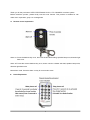
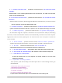
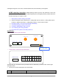
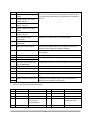
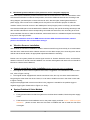
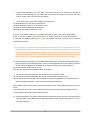
GSM/GPS CAR ALARM SYSTEM
User’s Manual
Model: VC-366GSM&GPS, VC-398GGTBA,
VC-390GGT,VC-390GGTB
1
z
Product Assembly Listing
1. Mainframe x1
2. Remote Controllers, work frequency: 43.92Mhz x2
3. Dial up device, work frequency: 433.92Mhz x1
4. Vibration sensor box, tele-control receive inside, work frequency: 433.92Mhz x 1
5. Alarm x1
6. Microphone and voice speaker with cable x1
7. GPS Antenna: 3.3VDC x1
8. GSM Antenna: 900/1800Mhz x1
9. Relay, 14VDC/40A x1
10. 20 pin cable x1
11. SOS button with cable x1
**There is no dialer for VC-390GGT
2
Thank you for the purchase of VTEC ELECTRONIC HK CO., LTD. GSM/GPS car alarm system.
Before install the product, please kindly read this user manual. This product is suitable for indi
vidual and corporation group car management
z
Remote control explanation
Alarm on: Press the defense key once, door lock the anti-theft setting, speaker beep once, direction light
flash once.
Alarm off: Press the remove defense key once, doors unlock to release anti-theft, speaker beep twice,
direction light flash twice.
Mute alarm mode: Press the alarm on key for 3 seconds to mute
z
Dialer Explanation
3
z
LED Status Direction
¾ Alarm off, LED, unlighted
¾ Learn or car repairing mode, LED, long time lighting
¾ Keep flashing for 4 times, stop for 2 seconds in the alarm on; there is no GPS signal
¾ Triggered in the alarm on, LED keeps flashing rapidly
¾ No GSM signal, keep flashing for 4 times, stop for 2 seconds
¾ Alarm on, GPS data success orientation, flashing twice and stop for 2 seconds
¾ Alarm on, vibration sensor been closed, flashing for 6 times and stop for 2 seconds
¾ Alarm off (LED does not shine)
Product Characteristic:
1. Dual password: GPS correlative setting is using the center password, initialization password is
654321;
Common used functions is using the user password, initialization password is 123456
2. Supported the two center services provided, users can choose the service center according to the
own needs.
▲Phone Operation Instruction:
Please call the GSM network anti-theft Sim-Card no, then you will heard “Welcome to use GSM
anti-theft system”
1、
When the system is under the de-activated status, system will indicated “for calls, please press
1; for system operation, please press 2”
2、
If you press 1, you will hear “please wait while we are connecting your call”. Meanwhile, the
tones will indicated the car owner, if the car owner doesn’t wished to answer the call, please
press “*” to hang up the phone, else please press “#” for answer the call.
3、
If you press 2 or when system is under the anti-theft status, then you will hear “please enter the
system operation password, press pound key (#) to end”.
4、
If your entered password is wrong, then you will hear “you have entered a wrong number,
please re-enter and press pound key (#) to end”.
5、 If the password entered is correct, then the function operated will indicated:
4
A、1、Activated car anti-theft mode”; operations succeed instruction: “Car locked and anti-theft
activated. ”
Mainframe will “bi” once, direction lights will flash once at the same time, car center control is locked;
System is in the activated mode.
B、“2、De-activate car anti-theft mode”; operations succeed instruction: “Car unlocked and anti-theft
deactivated;
Mainframe wills “bi” two times, direction lights will flash twice at the same time, car center control is
unlocks; System is in the de-activated anti-theft mode.
C、“3、Enable car operation”; operation succeed instruction: “Enable car operation Operation OK”;
System is activated the restrictions for the car power cut off. The engine power supply is recovered.
D、“4、Disable car operation”; operation succeed instruction: “Car operation already stopped”;
Be careful when using this car power cut off function. This is to prevent the traffic jam; after setting
this function, remote controller will be unable to control automatically; if wished to recover back the power
supply and the remote controller, please press 7 to enter the second menu and press 3 to activate the
remote controller.
E、“5、Monitor car status”; operation succeed instruction: “Monitor car status Operation OK”
System connected with car microphone, users can monitor the inside car activity via phone.
F、“6、Call in car”; operation succeed instruction: “Call in car Operation OK”;
After activated this function, you can talk with the person who inside the car
G、“7、Set other system functions”; after operation, enter to the other system functions menu
H、“8、Alarm number and password settings” after operation, enter to the alarm setting menu
I、“9、 Inquire about car current position”;
System will broadcast the car current longitude and latitude, latitude is in the front while
longitude is in the back
J、“0、Inquire about car working conditions”
After operation, system will according to the alarm report status or current working mode to give
the instructions:
“ Violent shock alarm during car anti-theft”
“ Unauthorized car opening alarm “
“Unauthorized started the car engine”
“ Car power cut off alarm”
“Car owner is in danger and request for help “
If system doesn’t have the alarm report, this is indicates the current working mode
5
▲ After the selection of number 7 enter the second level functional operation in voice
menu notice.
A、“1、Remote Control instructions”
After succeed to control in 8 seconds, can learn the new remote controller, system is using
the recycle preserve method, 6 remote controller preserve is the maximum, when the
learning device quantity is more than 6 hours, the earliest remote controller will
automatically eliminated
B、“2、System alarm off”; operation succeed instruction: “System alarm off Operation OK”
When system is under the deactivated status, remote controller function is only to
lock/unlock the door. At the same time, briefness indication for once; LED status is long
time lighting.
C、“3、Activate system alarm function”
operations succeed instruction: “Activate system alarm function Operation OK” Activated
all the functions.
D、“4、Shock test off”operation succeed instruction: “Shock test off Operation OK”
Closed the vibration sensor, turnaround light flashing for 4 times rapidly; after deactivated the
anti-theft setting and re-activated the anti-theft system once again, vibration sensor will
automatically recovered.
E、Press 5 to activate the vibration sensor. Then you will hear the operation succeed notice
F、Press 6 to activate the voice indication. Then you will hear the operation succeed notice
G、Press 7 to deactivate the voice indication. Then you will hear the operation succeed notice
H、Press 8 to reset the anti-theft mainframe, other setting functions will recover back.
**From E to H, there is no voice indication here, but these functions still remain inside the
device.
If your operation is succeed, you will heard the music.
I、Press “*” to return to the main menu
5、Press 8(8、Alarm number and password settings)
A、“1、Set 1st alarm phone number.” Set the first alarm phone no
B、“2、Set 2nd alarm phone number” Set the second alarm phone no
C、“3、Set 1st help phone number”
Set the first SOS help phone no
D、“4、Set 2nd help phone number”
Set the second SOS help phone no
E、“5、Set system operation password” Press 5 to change the personal user password
F、“6、Phone alarm”
Choice the phone alarm
G、“7、Short message alarm”
Choice the short SMS alarm
6
Attention: We are strongly recommended that phone reporting is more reliability cause SMS
reporting is depends the country’s network signal.
J、“Press star key (* )to return to the main menu” Press “*” key to return to the main menu
System is setting the password or mobile phone no, entered and the instruction is: Please
re-enter the setting no, if you have wrongly entered the password twice, you will hear the
instruction: You have entered a wrong number, please re-enter. Please “#” key to end.
If you have correctly entered the password, the instruction is: operation ok
6、 Please using the center password to enter: password: 654321, enter the GPS setting menu
A、“1、Set private user” operation succeed instruction: “Set private user Operation OK”
After chosen the function, user can using the activate or deactivate car position inquiry, if user is sending
SMS to request the car position, the system will automatically return to the car longitude and latitude.
User can use the longitude and latitude to track the car position by using PC. Example: user sending the
“DW password” to the car mainframe no, after received the returned message “RFID6131300012”; X:
23031000; Y: 11346.0670
RFID is the user car mainframe ID, the number behind X is the latitude and number behind Y is the
longitude.
User cans also using the provided software to track the car position.
You can track the car current location by using Google map; System is set as default (private user)
7
Our device has another fantastic function which can support Google Map. So, no matter you are
the personal users or group users, you still can use our device to track your vehicle, even if you
don’t have our group software. Google map will give you a good taste. Please log on to
www.earth.google.com, download the Google Earth and then install on your computer or laptop.
You have to set it to the individual user, sent it to “DW password” into the device. When you get
the latitude and longitude information by SMS from your vehicle which have installed our device,
just put SMS information into Google map and press search button, (you will get the position of
your vehicle at once 23 03 31.383"N 114 29 30.33"E please refer to the black circle above,
attention: all the comma and symbols must be fill inside, else you can’t find the car position)
Input longitude and
latitude data received
by short message
The car present
position
B、“2、Set group user”, operation succeed instruction: “Set group user Operation OK”
After choose the function, user SMS “DW password” to the device, after received the
instructions, device will send the car current position and working status to the first control
center number, then you will received the returned message from the center with the
longitude and latitude. If user SMS “DE password” to the device, after received the
instructions, device will sending the interrelated car position to the second appointed control
center number.
Device will SMS to the first center number when doing the reporting.
C、“3、Set group monitor call number
messages)
1” Set the center number (received all the device
D、“4、Set group monitor call number 2” Set the center number (received all the device messages)
**Backup for the group monitor call number 1
E、“5、Set system operation password” Changed the center password
G、“6、Inquire about car current position” Operation succeed notice: Read all the received position
8
messages through the voice notice, read the latitude first, then followed by the longitude
▲SMS reporting instruction: (SMS reporting content is just for the references, we are not
guarantee that all the regions can do the SMS reporting due to the signal problem); Others version for
the SMS reporting is in English version
1、 Alarm phone number change successful!
2、 System messages inquiry: Mainframe no, setting alarm phone number 1, setting alarm phone
number 2, setting help number 1, setting help number 2, control center number
3、 Emergency alarm. Car owner request help immediately
4、 Automotive illegally to report to the police
5、 someone is attempting to open your car
6、 car is suffering from strong vibration
7、 Be careful! The system is unusually switch off
Installation:
一、 Product’s antenna port instructions
GPS Antenna
GSM Antenna
Speaker LED
MIC
(port 1)(port 2)
PUT SIM CARD
二.Product main control line output description:
Vibration Port
10 9
8
7
6
5
4
3
2
1
11 12 13 14 15 16 17 18 19 20
Vibration test port connected to the up-vibration test box. Meanwhile, provide the tele-control signal
received function.
1、 20 Pins port functions description are shown below:
No
1
Name
Center control close, open
Functions
Middle control lock control the output extremity, please read
9
2
3
always, NC port
the backside description after a concretely install, ought to the
Center control close, signal
function is to provide the phone long distance on/off car door
output
lock used/ for the customize 24V, system doesn't consist this
Center control close, close
function
always, NO port
4
Center control open, open
always, NC port
5
Center control open, signal
output
6
Center control open, close
always, NO port
7
Light direction control
Separate connected to the car turnaround lights
input/output
8
Light direction control
input/output
9
Alarm horn control output
Police report voltage output, provide output 12V/3A to the
energy sources to drive the electronic speaker
10
Positive power supply input
Connected to the electric flask in positive 12V to provide the
power supply
11
Minus power supply interface
Connected to the negative electric flask
12
GND
Connected to the SOS button
13
SOS test
14
Car Audio control (only valid
Outside relay connection control is needed to control car audio
for VC-398GGTBA)
15
Engine power off output
Control the 40A relay motion to cut off the engine power supply
16
Car door test/ minus triggered
Use to test whether the car door is open or close
17
Foot brake test
Connect to foot brake on/off
18
ACC state test
Connect to ACC On position, test whether the car is on fire or
not
19
Middle control lock signal test
Changed it to the updated version, then connected to the
center control, up/down lock signal test
20
2. 20 Pins color rank and functions description:
No
Color
1
Orange
2
Functions
No
Color
Center control off, NC
11
Black
White
Close signal output
12
Purple Grey
3
Yellow
Center control off, NO
13
Green yellow
SOS test
4
Orange/Black
Center control on, NC
14
Orange/Black
Outside hang relay
(only valid for
Functions
Minus power supply
control back case
VC-398GGTBA)
5
White/Black
Open signal output
15
10
Yellow
Power cut
output/Outside
connected relay
6
Yellow/Black
Center control on, No
16
Blue
Car door test/minus
triggered
Brown
Connected to car
17
Orange
Foot brake test
8
Brown
turnaround lights
18
White
ACC ON test
9
Pink
Police report
19
Brown
20
Green
7
output/Police report
received
10
Red
Positive power supply,
12V
z
Center Control Lock Wiring Chart:
11
z
Mainframe System Installation (This product is suit for 12V power supply car)
Mainframe system installation position should be under the meter board or in the front seat shelter, make
sure that the mainframe is under the fixed position, then let the GSM anti-theft exit line according to the
wiring diagram, port description connect with the car ACC, direction lights, brake lights and also the
power supply; Don't connect in the middle part of wire just for the convenient purpose. If suffer the
condition restrict, forced to connect in the middle part of wire (if engine power cut off loop), should make
sure that the middle part of wire located with the isolation bind up, then put all the wiring harness pin and
also the GPS mainframe’s socket corresponding connected with each other, then according to the front
recommendation function to make the initial test, make sure there are no mistakes and pack the wire tidily,
then put it in the origin position.
**Distances should be reserve for GSM antenna and the GPS anti-theft mainframe; antenna
position should follow the car state when setting it.
z
Vibration Sensors Installation:
After finished the mainframe installation, vibration sensors should fix-up (close to body or to install meters
near the site to make sure that the vibration sensors is in the detect scope), then according to the size of
vehicle and the actual needs, do appropriate adjustments detection sensitivity.
Please note: the system placed the remote signal receiver in vibration detection boxes, and therefore,
attention is drawn to remote antenna installation can not bear tied together with other wire rod should be
left free to enhance remote distance;
z
Central control door locks installation (below are the few types of installation)
1. The original car door locks no impetus to door locks, a suggestion is to install electric center control
lock, refer to Figure 2 wiring;
2. The original vehicle equipped with central control door locks, but only one driver seat’s switches to
bring along the other three door locks. Hence, it is can also to install one motor in the driver’s seat. refer
to Figure 4 wiring;
Original cars equipped with central control door locks, judgment is needed for the positive trigger or
negative trigger types. Please refer to Figure 2, 3 wiring.
z
System Problem & Solve Method:
1、 Firstly, please make sure that the system Sim-Card has been installed; Check the power supply
on/off.
2、 Finished the Sim-Card installation and on the power supply, and hear “notice,GSM net signal
faintness”, please re-check does the Sim-Card is installed well and re-install the Sim-Card
once again.
12
3、 Finished the installation, you can’t call in the system phone, this is because the mainframe
battery is in the charging way, you need to wait for one hour for re-test. If you still can’t call in the
phone, please press 3 for phenomena checking.
4、 If the system can’t do the alarm called out; please check:
(A) GSM antenna is in the right connecting way
(B) New installation, wait for 1-2 hours for re-check
(C) Please check the GSM Sim-Card balance
(D) Please make sure the alarm no is right
5. When you wished to repair your car, please remember to switch off the whole GPS system.
Go to “7. Set other system functions” then go into “2. System alarm off” to switch off the system.
6. After the car repaired, please go to “7. Set other system functions”, then go into “3. Activated
system alarm function ”
7. If you forgot the system entering password and the system is indicated that this is the
wrong password, this is because you have forgot the new password after the setting, this
device manufactured password is 123456. (if you have set the alarm phone no and the
police report method is set by using phone call. Please purposely let the device make the
police report, you can amend the password according to the menu voice indication)
8. Remote controller is unable to control after system reporting, it is because GSM signal transmit
power is bigger in the weak signal place. This is a normal phenomenon when system is unable to
control in the long distance in the beginning of system reporting, the resolve method is:
(A) Put the remote control nearby the car
(B) Carry through the control operation after 10 seconds.
9. No matter in what circumstances, the remote control is unable to control:
(A) Car will automatically deactivated the remote controller after the power cut off
(B) You have been choosing the phone reporting by using phone operation, the resolve method is
enter the system and press 7, then follow the indications and press 3.
Here, please check does the remote controller is able to function, else repeat the above action for 3
times.
If it is still unable to function, please check does the remote controller’s battery voltage is in the
normal voltage, normal voltage should be 2.5V-3.3V.
10. System reporting is only done by SMS reporting, without the phone reporting. This phenomenon
has been set by using SMS to do the reporting. Please enter the system and press 7 to re-set
the phone reporting.
13
11. System can’t do SMS reporting, please checks the system anti-theft mainframe Sim-Card, does
the SMS center no is correctly set, else please re-set by using another mobile phone.
12. Step on the brake but doors are not auto lock, please check does the foot brake is correctly
connect, else, correct it.
---------------------------------------------------------------------------------------------------------Technology is keeping advances and advances, products are constantly updated, VTEC have the
reservation right to change or modification the performances or functions for the products without any
further notices; In order to know the latest information, please logon to www.china-vtec.com or direct
call to our sales department.
This manual notes that, VTEC has the final interpretation rights.
14