1
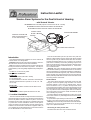
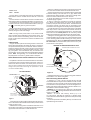
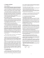
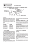
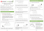
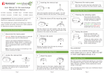
Connevans
Solutions to improve the quality of life
This product may be purchased from Connevans Limited secure online store
at www.DeafEquipment.co.uk
DeafEquipment.co.uk
Solutions to improve the quality of life
Instruction Leaflet
Smoke Alarm Systems for the Deaf & Hard of Hearing
- with Strobe & Vibrator
Ei 169/160 BASIC SYSTEM (requires a Smoke Alarm Ei161 or Ei166)
Ei 170/160 with MAINS IONISATION SMOKE ALARM Ei 161
Ei 171/160 with MAINS OPTICAL SMOKE ALARM Ei 166
SMOKE ALARM
Ei 161 or Ei 166
T
T
NO
N
PAI
STROBE
TEST
PUSH
& HUSH
UNCL
(With rechargeable battery
for one week standby)
PATTRESS Ei 172/160
DO
CONTROL PANEL Ei 173
IP &
SL
IDE
VIBRATION PAD Ei 174
Introduction
This leaflet describes the installation of the Ei 169/160, Ei
170/160 and Ei 171/160 Systems.
Important: Read all instructions before installing. This leaflet must be left with the end user after installation.
N.B. If the system is not being used for some tme the Control
Panel power switch must be in the off position. This will prevent the battery from being totally depleted and possibly damaged.
Do not turn on until it is fully wired.
The systems consist of:Ei 169 / 160
Ei 173 Control Panel (with built in strobe)
Ei 174 Vibrator Pad
Ei 172/160 Pattress for Smoke / Heat Alarm Interface (this
requires an Easi-fit Alarm to operate i.e. Ei 140, 141, 146,
161 or 166)
Ei 170 / 160
Ei 169/160 with a Mains Ionisation Smoke Alarm Ei 161
Ei 171 / 160
Ei 169/160 with a Mains Optical Smoke Alarm Ei 166
1. Location & Installation
The Control Panel should normally be fixed such that the internal strobe light can be seen from the bed and the vibration
pad can be placed under the mattress or pillow. It has to be
powered from the mains (230 VAC) so a suitable power point
or junction box must be available to which it can be permanently connected. The Smoke Alarm must be located as described in the Smoke Alarm instructions supplied. Cable (10
m) is supplied to connect between the Control Panel and the
Ei 172/160 Pattress for the smoke alarm.
1
This can be extended up to 50 m (20 ohms max.) with suitable low voltage cable if required. The Smoke Alarm supplied
with the system may be interconnected with other Ei mains
powered smoke/heat alarms up to a maximum of 12 alarms
(see below for details) in total. Many dwellings require more
than one smoke alarm for minimum protection. See the smoke
alarm instruction leaflet for detailed advice on, interconnection, maintenance etc.
Warning: This mains operated system should be installed
and interconnnected by a qualified electrician in accordance
with the Regulations for Electrical Installations published by
the Institute of Electrical Engineers (UK). Failure to install this
system correctly may expose the user to shock or fire hazards.
Mains (230VAC) rated cable must be used for the interconnect
wire along with the mains itself.
Control Panel
The Control Panel should be permanently fixed to the wall
using the screws and plastic plugs enclosed. The screws
should be spaced 114 mm (4.5 in) vertically apart. The top
screw should be 27 mm (1.1 in) below the top surface of the
control panel when installed. The screws (large heads) should
be screwed into the wall leaving a gap of approximately 4 mm
(0.15 in) under the head. Fit the keyhole slots on the back of
the control panel over the screw heads and slide the panel
down vertically into position.
The mains adaptor can be plugged into a socket. The socket
must not be used for any other equipment and it must always
be switched on.
It is preferable to permanently wire the unit into a mains junction box. In this case remove the plug and wire as follows.
Warning: First remove the power to the circuit at the distribution board. If you are in any doubt about how to do this, get
help from a qualified electrician.
Connecting to mains junction box.
The mains lead wires are colour coded as follows:
2
brown: live
blue: neutral
The wire which is coloured blue must be connected to the
terminal/wire which is marked with the letter N or coloured
black.
The wire which is coloured brown must be connected to the
terminal/wire which is marked with the letter L or coloured red.
The apparatus is not to be earthed, so no connection is to be
made to terminals or wires marked with the letter E, the symbol
or coloured green or green and yellow.
Bring the low voltage wiring from the control panel to where
the smoke alarm is to be located. Route all wires neatly and
securely along the walls and ceilings.
Note: Turning off the power switch on the Control Panel
does not switch off the apparatus from the supply mains. The
switch removes the AC and battery power from the Control
Panel, but the mains transformer remains connected to the
supply mains.
Vibration Pad
Plug the vibration pad into its locking socket on the control
panel. Place the vibration pad under the pillow or mattress. It
is important that the person in the bed can feel the vibration check it is sufficient to wake a person by lying on the bed and
pressing the test button on the control panel - see also “Testing your system”. Some mattresses may not transmit sufficient vibration, and in these cases it should be fitted under the
pillow. Note: During testing, or in an actual alarm situation,
the pad pulses on and off for greater effect on sleepers.
3. The low voltage wiring from the control panel must not be
run in the same conduit as the mains/interconnect wires.
4. Using a sharp knife remove material from the appropriate
knockouts making sure that there is no gap, either where
mated with the ducting/conduit or with the low voltage wires.
There are three knockouts and one on the rear.
5. Screw the pattress to the surface using the two screws
and plastic plugs supplied.
6. Figure 1 shows the connections. Connect the incoming
live, neutral, and interconnect (from other smoke alarms if
present) to the pre-wired connector block. The Pattress does
not require an Earth. The three wires for connecting to the
smoke alarm mounting plate are already wired to the pattress.
Connect the red wire (remove the small piece of insulating
tape first) from the control panel to the terminal marked “R”
and the yellow wire to the terminal marked “Y”. The black and
blue wires from the control panel are not used. They should
both be connected to the spare terminal for extra strain relief.
7. Bring the mounting plate wires out through the hole in the
mounting plate as shown in figure 2. Connect the three wires
to the mounting plate terminals following the wiring colours
specified in figure 2. Note: The white interconnect wire must
be connected to the smoke alarm (even if there is only one
smoke alarm on the system).
SMOKE ALARM MOUNTING PLATE
WIRING FROM PATTRESS Ei172/160
Mains Smoke Alarm Interface Pattress Ei 172/160
The pattress is used to mount the smoke alarm in its location,
to connect it to the mains and interconnect wires, and to connect it to the wires from the Ei 173 control panel. (The connections from the non-isolated mains powered smoke alarms, to the low
voltage control panel wires are through an opto-isolator in the Ei
172/160 for electrical safety).
PATTRESS WIRING
IC
N
LIVE (BROWN)
INTERCONNECT (WHITE)
NEUTRAL (BLUE)
Figure 2
TO EASI-FIT SMOKE ALARM
MOUNTING PLATE
8. Replace the wiring cover on the mounting plate. Slide the
Smoke Alarm on to the mountig plate.
L - BROWN
IC - WHITE
N - BLUE
Interconnecting Smoke Alarms
REMOTE
L
IC
N
TO CONTROL
PANEL Ei173
CONDUIT
L
R - RED
Y - YELLOW
- SPARE TERMINAL
IC
LIVE
N
INTERCONNECT
TO OTHER SMOKE/HEAT
ALARMS (IF PRESENT)
L
PLATE
FIXING
SCREWS
NEUTRAL
Figure 1
1. Choose the mounting position following the siting instructions in the Smoke Alarm leaflet. Remove the power from the
circuit you plan to use.
2. Where the incoming mains and interconnect wires are on
the surface of the ceiling or wall the appropriately sized ducting/conduit must be chosen to mate with the unit.
3
A maximum of 12 Ei 140,141,144,145,146,161,164,166
Smoke/Heat Alarms may be interconnected to one Ei 172/160
unit. When one alarm senses fire all interconnected units will
sound and the control panel will turn on the strobe light and vibration pad (See Smoke/Heat Alarm instruction leaflet for further details on interconnection wiring).
Warning: Do not connect to any other type of Smoke/Heat
Alarm. Doing this may damage the alarms and could result in a
shock or fire damage.
N o t e 1 : A n a l a r m w i t h b a t t e r y b a ck- u p ( i .e . Ei
141,144,146,161,164,166) will continue to operate during
mains failure and will be able to signal the control panel if they
sense fire.
The control panel also has battery back-up, so that it too will
operate during mains failure.
4
2. Testing your System
After Installation
1. Turn on the AC mains power to the smoke alarm circuit.
Check the continuous green light is visible on the smoke alarm
cover. The red light on the unit will flash every 40 seconds.
2. Plug in the control panel mains adaptor (or turn on the AC
mains if it is connected to a junction box). Slide the power
switch on the side of the unit to the “on” position. Check the
continuous green light on the control panel cover is visible.
3. Press the test button on the smoke alarm. The smoke
alarm should sound and the red light will flash every second.
After about 4 seconds the control panel will start flashing the
strobe light and the vibration pad will turn on. Two people may
be needed for this test. Interconnected smoke alarms (where
present) should also be tested in similar fashion.
4. Press the control panel test button. Check the vibration
pad is on and that the strobe is flashing.
not on, check the wiring to the mains and that the mains is not
off (e.g. due to a tripped circuit breaker or fuse). Check the
power switch on the control panel is on.
The control panel monitors the wiring to the vibration pad
and the smoke alarm pattress for faults.
(i) If the vibration pad is removed or if its wiring is open circuit, the control panel will flash the strobe.
(ii) If the wiring to the smoke alarm pattress is disconnected,
open circuited or short circuited, the control panel will turn on
the vibration pad and the strobe light.
There are no user serviceable parts in this unit. If it is thought
to be defective, it must be returned to the manufacturer for repair or replacement (see “Product Guarantee” section).
4. Accessories and other Features
Control Panel “Aux. Output”
Daily & Weekly Testing
We recommend that you test your system weekly by pressing all the smoke/heat alarm test buttons and checking that
the vibration pad and strobe light are operating. Also check at
the same time that the green power lights are visible on both
the smoke alarm(s) and the control panel.
Check daily that the vibration pad is in its correct position by
pressing the test button on the control panel.
Periodic Testing of Rechargeable Battery
The rechargeable battery takes about 20 hours to charge
from the control panel when it is first powered up. The panel
then maintains it in the fully charged state by continuous
trickle charge. In the event of a mains failure the battery will
power the system in standby for a week followed by at least 4
minutes alarm. When the mains fails, the green light is extinguished and the red light flashes rapidly on the control panel to
indicate it is on battery power. If the battery is starting to be
fully depleted the red light will go off to indicate the control
panel is totally unpowered. The battery will last 5 years in normal use provided it is not exposed to extremes of temperature
for prolonged periods, or fully discharged/charged a large
number of times.
We recommend that the functioning of the rechargeable
battery is checked at least yearly as follows:
(i) Ensure the control panel has been mains powered for at
least the previous 20 hours for the battery to charge.
(ii) Turn off the mains power to the control panel by unplugging it or switching off the circuit at the distribution board.
Check that the green light goes off and the red light starts to
flash.
(iii) Press the control panel test button for 20 seconds and
check the strobe flashes brightly and that the pad vibrates
strongly. Check that the red light continues to flash while the
test button is pressed. (Cover the strobe light with a card to
stop this dazzling you while looking for the red light). This red
light flashing indicates that the battery is satisfactory. If the red
light goes off, or if the strobe is weak, or if the vibration is weak,
the battery will need to be replaced. Contact the nearest address in this leaflet for advice about getting a replacement.
Replace Ei173 control panel after 5 years operation. (See
date on side of panel).
The auxiliary output turns on when the control panel is in alarm
and can supply up to 200 mA at 12 Volts (range 10 to 14 Volts).
(Note: the positive terminal is the pin next to the “Clock Input” socket). An
Auxiliary Strobe Ei 178 is available and is supplied with 10 m of
cable and a suitable plug. It can be located, for example, where it
is readily seen during the day (e.g. downstairs hallway). An extra
Vibration Pad Ei 174 is available with 2 m of cable and a plug for
connecting it to the auxiliary socket.
Control Panel “Clock Input” socket
A suitable alarm clock (with a 5 to 24 Volts AC or DC output electrically isolated from the mains supply) can be connected to
this input socket with a 3.5 mm mono jack plug. When the alarm
clock triggers, the vibration pad turns on to wake the person, but
the internal strobe or auxiliary output do not turn on.This lets the
user know it is a wake-up call and not a fire. Therefore the user
needs only one vibration pad under their pillow or mattress.
Triggering Control Panel into Alarm Externally
A manual fire alarm switch (e.g. a glass break type) can be used
to get the control panel to turn on the vibration pad and strobe
light. This is done by connecting the red and yellow wires, from the
control panel, together, with the switch (or volt-free relay isolated
contacts). The wires from the switch can be connected into the circuit at the pattress terminals.
Note: This does not cause the smoke alarm to sound.
Adding an Ei 128R Pattress with relay to the system
The Ei 128R Pattress is used where volt-free relay contacts are
required to signal to other equipment when one of the smoke
alarms sense fire. For example the relay can be used to signal to a
warden call system, or to turn on lights.
This requires the system to have at least two smoke/heat
alarms. The first smoke/heat alarm should be mounted on the
pattress Ei 172/160 as described above. The second smoke / heat
alarm, interconnected to the first, should be mounted on the relay
pattress Ei 128R. When any smoke alarm senses fire the Ei
172/160 pattress will signal the control panel into alarm and the Ei
128R pattress will switch its relay contacts.
(Note: The Ei 128R will not operate without a 230VAC mains
supply).
Power Requirements
The typical currents at 230 VAC are
· Standby 10 mA
· Alarm
50 mA
3. Troubleshooting
If the units fail any of the above tests after installation, the
system has probably been incorrectly wired and/or all units
are not connected. Check all wiring carefully. If the green
power lights on the smoke alarm and/or the control panel are
5
6
5. Product Guarantee
Ei Electronics guarantees this system for 5 years from the
date of purchase against any defects that are due to faulty materials or workmanship. This guarantee only applies to normal conditions of use and service, and does not include damage resulting
from accident, neglect, misuse, unauthorized dismantling, or contamination howsoever caused. This guarantee excludes incidental and consequential damage. If this system should become
defective within the guarantee period, it must be returned to the
nearest address in this leaflet. It must be carefully packaged with
the power switch on the control panel in the off position, and with
the problem clearly stated along with proof of the date of purchase. We shall at our discretion repair or replace the unit. Do not
interfere with the system or attempt to tamper with it. This will invalidate the guarantee, but more importantly may expose the user
to shock or fire hazards.
This guarantee is in addition to your statutory rights as a consumer.
Manufactured by: Ei Electronics.
Shannon, Co. Clare Ireland.
www.eielectronics.com
Distributed by: Aico Limited.
Mile End Business Park, Oswestry,
Shropshire, SY10 8NN, U.K.
www.aico.co.uk
© 2002
P/N B14698 Rev 1
7