1
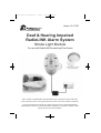
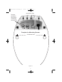
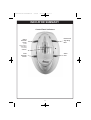
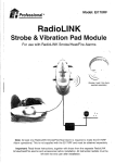
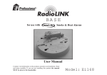
Connevans.info
e
Offering you choic
se
Helping you choo
Solutions to improve the quality of life
This product may be purchased from Connevans Limited
secure online store at www.DeafEquipment.co.uk
DeafEquipment.co.uk
B16566-R0-Ei171RF-ENG-UC
2/9/09
2:54 PM
Page 1
Model: Ei171RF
Deaf & Hearing Impaired
RadioLINK Alarm System
Strobe Light Module
For use with RadioLINK Smoke/Heat/Fire Alarms
(Smoke / Heat / Fire Alarm
supplied separately)
Note: At least one RadioLINK Smoke/Fire/Heat Alarm is required to make the Ei171RF
Alarm operational. This is not supplied with the Ei171RF and must be obtained separately.
Important: Read these instructions, together with those from the separate RadioLINK
Smoke/Heat/Fire alarms and accessories before installation. All instruction leaflets must be
left with the end user after installation.
B16566-R0-Ei171RF-ENG-UC
2/9/09
2:54 PM
Page 2
The Ei171RF is for use with the following Ei RadioLINK Smoke/Fire/Heat Alarms and Accessories.
Mains Multisensor/Smoke/Heat/Fire Alarms: Ei2110, Ei160RC & Ei140 Series Alarms in
conjunction with an Ei168RC RadioLINK Base.
Battery Powered Smoke / Heat Alarms: Ei3100RF, Ei3103RF, Ei3105RF, Ei405, Ei405TY, Ei605C
(with RF module), Ei605TYC (with RF module).
Deaf & Hearing Impaired RadioLINK Alarm System: Ei170RF.
Accessories:
Ei407 Manual Call Point, Ei410 Remote Control (portable), Ei411H Remote Control (wall mounted),
Ei428 Relay Module, Ei408 Switched Input Module.
1. INTRODUCTION
This leaflet describes the installation of the Ei171RF and its integration into a total RadioLINK Fire
Alarm System, incorporating a choice of Smoke/Fire/Heat Alarms and Accessories.
N.B. It is essential that the Ei171RF is connected to the mains to preserve its one-week battery
standby. Leaving the unit operating without mains connected will completely deplete the battery and
possibly damage it. (If the Ei171RF is not being used for a prolonged period and cannot be left plugged
in to the mains, then disconnect the battery).
Location
The Strobe Module should normally be fixed such that the internal strobe light can be seen from the bed.
An additional strobe module can be then placed in any other living area of the house which can be readily
seen by the occupant. It has to be powered from the mains (230VAC) so a suitable socket or junction box
must be available to which it can be permanently connected.
The back-up battery in the Strobe Module must not be exposed to excessive heat such as sunshine,
heaters, fires or the like.
The associated RadioLINK Alarms and Accessories must be located and installed as described in
their own instruction leaflets.
2. INSTALLATION
Strobe Module Ei171RF
The battery must first be installed in the Strobe Module. Open the rear compartment by squeezing
together the two latches as shown in Figure 1b, and lifting the cover off.
Auxillary
Socket
Squeeze
Here
Conversion
Jack
Squeeze
Here
Wire
Channels
for mains lead
(and accessories
if required)
Mounting
Screw
Holes
Battery
Cover
Model: Ei170R
RadioLINK Fire Alarm Panel for
Deaf & Hard of Hearing
For use with RadioLINK Smoke Alarms
1. Connect battery plug & then plug in mains.
2. After installation, house code system by pressing
house code switch with a small screwdriver or simila
Figure 1a
Figure 1b
Squeeze as shown to open
battery compartment
2
B16566-R0-Ei171RF-ENG-UC
2/9/09
2:54 PM
Page 3
Battery
Battery
Plug
Latch
Figure 2
Plug the battery into the socket at the rear of the battery compartment as shown in Figure 2 (while
holding the small latch on the battery plug, open). Place the battery in the compartment ensuring the
notch in the battery is used to leave clearance for the plug and sockets (see Figure 3).
Battery
Clearance
Notch
Figure 3
Shows battery orientation - Dress the battery leads as shown, replace the battery cover and
push firmly down on the two latches
The Strobe Module can be left on a table or permanently fixed to the wall using the screws and plastic
plugs enclosed.
If fixing to a wall, the screws should be spaced 95mm (3.7 inches) horizontally apart. The top screws will
be 70mm (2.7 inches) below the top surface of the Strobe Module when installed. The template at the
end of this leaflet can be used to locate the screws accurately. The screws (large heads) should be
screwed into the wall leaving a gap of approximately 4mm (0.15in) under the head. Fit the keyhole slots
on the back of the Strobe Module over the screw heads and slide the panel down vertically into position.
The mains adaptor should then be plugged into a socket (or permanently wired to a mains junction box
- see overleaf). This mains socket must not be used for any other equipment and it must not be switched
off. The mains plug must be readily removable (so the mains can be disconnected if necessary).
3
B16566-R0-Ei171RF-ENG-UC
2/9/09
2:54 PM
Page 4
If connecting to a mains Junction Box
It is preferable to permanently wire the unit into a mains junction box. In this case remove the
plug and wire as follows.
Warning: If the plug is being removed and the unit is being wired to a junction box it should be
installed by a qualified electrician in accordance with the Regulations for Electrical Installations
published by the Institute of Engineering & Technology (UK) BS7671. Failure to install this
system correctly may expose the user to shock or fire hazards.
First remove the power to the circuit at the distribution board.
The mains lead wires are colour coded as follows:
Brown: Live
Blue: Neutral
The wire which is coloured blue must be connected to the terminal/wire which is marked with
the letter N or coloured blue.
The wire which is coloured brown must be connected to the terminal/wire which is marked with
the letter L or coloured brown.
The apparatus is not to be earthed, so no connection is to be made to terminals or wires marked
with the letter E, the symbol
or coloured green or green/yellow.
The Strobe Module must not be exposed to dripping or splashing and items filled with liquids such as
vases must not be placed on or above the apparatus.
3. SETTING UP THE RadioLINK SYSTEM
This system uses radio to communicate between the Fire Alarms, Accessories and the Strobe Module.
It is set-up simply by putting all of the units into “House Code Mode” and letting them automatically
code with each other. This will “House Code” the installation so that they will not accidentally signal to,
or be affected by, nearby systems.
The units will all communicate with each other (providing they are within range), as delivered i.e.
without any House Coding - however it is recommended that they are House Coded as follows:
3.1.1 Install & power all the elements of the system.
3.1.2 Press the House Code switch on all units – see individual instruction leaflets for switch locations.
On the Strobe Module, the House Code switch is pressed by means of small screwdriver (or similar,
diameter of top less than 3mm), through the access hole on the top of the unit – see figure 4.
3.1.3 Press and hold the Strobe Module House Code button until the blue RadioLINK light comes on.
Release it and the light will flash every five seconds.
3.1.4 When all units are set into ‘House Code Mode’ they should signal to each other and set-up their
network automatically.
3.1.5 Each unit will now flash its blue or amber light to show how many units it is RadioLINKED with. If the
Strobe Module is linked to just one smoke alarm they will both flash twice. With 6 units for example, 4 Smoke
Alarms, 2 Strobe Modules, each unit will flash six times. A maximum of twelve RF units can be linked this
way.
3.1.6 If some units flash less than the expected number of times, after being in House Code Mode for
over 10 minutes) they are out of range of each other.
Follow the advice in the RadioLINK instructions supplied with the other alarms to resolve this.
3.1.7 The units will automatically exit the House Code Mode after 30 minutes. However we recommend
that you manually exit the House Code Mode by pressing and holding the House Code switch on the
4
B16566-R0-Ei171RF-ENG-UC
2/9/09
2:54 PM
Page 5
Strobe Module until the blue light turns on, then release. The blue light should stop flashing and an
‘exit House Code Mode’ radio signal will be sent to all other units. Check that the amber/blue lights on
all other units have stopped flashing. (if some units are still flashing it may indicate a problem with the
radio communication to this unit, or that the particular RadioLINK unit (Ei407, Ei410, Ei411H & Ei408)
does not have this automatic cancel House Code Mode feature and must be taken out of House Code
Mode manually. Check instruction leaflet supplied with the units. Manually exiting the House Code
Mode reduces the risk of accidentally House Coding your RadioLINK Bases with nearby systems.
Clock Input
(if required)
RadioLINK
Signalling
Blue
Mains
Indicator
Green
(mains
disconnected =
amber flash/
4 seconds)
House Code
Switch
Strobe
Fault
Indicator
Amber
ALARM
FAULT
Alarm
Red
TEST
Test
Button
Figure 4
Note: When the blue or amber light has stopped flashing on a unit it is out of House Code Mode – do
not press the House Code switch again as this will put it back into House Code Mode.
3.2 ADDING UNITS
To add units to the system simply repeat the above procedure, i.e. put all into House Code Mode, new
as well as old units, and ensure that the number of flashes shown equals the number of units in the
system. For the other RadioLINK components see their instruction leaflets.
3.3 RESETTING HOUSE CODES
Sometimes it is necessary to cancel the House Code learned i.e. to reset the units to the factory
settings. To reset the Strobe Module to clear the House Codes, simply hold the House Code button
until the blue light illuminates solidly, then starts to flash and then stops flashing, then release the
button, this will take about six seconds. For other RadioLINK components see their separate
instruction leaflets.
5
B16566-R0-Ei171RF-ENG-UC
2/9/09
2:54 PM
Page 6
4. TESTING AND MAINTAINING YOUR SYSTEM
4.1 AFTER INSTALLATION
4.1.1 Check that all RadioLINK Alarms and Accessories are powered correctly.
4.1.2 Check that the green light on the Ei171RF Strobe Module is continuously lit.
4.1.3 Press the test button on all RadioLINKED Smoke/Heat/Fire Alarms, Remote Controls and
Manual Call Points in turn, and check that all other Smoke/Heat/Fire Alarms in the system alarm after
about 4 seconds and that the Strobe Light Module activates. Also check that the RadioLINK
accessories were operated.
N.B. Wait 12 seconds before testing the next unit or if you wish to repeat testing.
4.1.4 Press the Strobe Module test button. Check that the strobe flashes and the red alarm light on
the Strobe Module flashes (this will also cause the Smoke/Heat/Fire Alarms to sound and also their
red lights to flash rapidly, and any other additional Strobe Module to flash).
4.2 DAILY & WEEKLY TESTING
Check daily that the green light on the Strobe Module is on constantly. We recommend that you test
your system weekly by pressing all the smoke/heat/fire alarm test buttons and checking that the strobe
light operates.
Check the Strobe Module indicator lights as follows (see figure 4)
4.2.1 Green mains power should be constantly on. If it is off check that it is plugged into the mains,
that the socket is not switched off, fuses, circuit breakers etc. If the mains is off, the green light will be
off and the unit will be running on the rechargeable battery. The green light will be replaced by an
amber flash every 4 seconds to indicate battery is satisfactory. When this amber flash stops, the
battery is depleted and the mains should be reinstated (If the mains cannot be reinstated at this time,
the depleted battery should be removed, until the mains can be re-connected).
4.2.2 Press the Test button on the Strobe Module and check that the strobe flashes, the red alarm light
flashes and that the blue RadioLINK light illuminates on for about 3 seconds indicating the radio test
signal is being sent to the Smoke/Fire/Heat alarms and any accessories.
4.2.3 Check that the amber fault light is not flashing every 4 seconds. If it is check that the conversion
jack is connected firmly to the socket with its plug latched (see figure 1). If this connection is
satisfactory, it is probably indicating that the battery is depleted. Connect the unit to the mains and
check after 24 hours that the amber fault light has ceased flashing.
4.3 PERIODIC TESTING OF RECHARGEABLE BATTERY
4.3.1The rechargeable battery can take up to 20 hours to charge when the unit is first powered up. It is
then maintained in a fully charged state by continuous trickle charge. In the event of a mains failure the
battery will power the system in standby for a week and then be capable of at least 4 minutes of alarm.
If the mains fails, the green light is extinguished and the amber light flashes every 4 seconds on the
Strobe Module to indicate it is on battery power. The amber light will also flash every 4 seconds if the
battery is almost depleted. Both the amber lights will go off to indicate the battery is depleted and the unit
is totally unpowered. The battery will last 5 years in normal use provided it is not exposed to extremes of
temperature for prolonged periods, or fully discharged & charged a large number of times.
We recommend that the functioning of the rechargeable battery is checked at least yearly as follows:4.3.2 Ensure the Strobe Module has been mains powered for at least the previous 20 hours for the
battery to charge.
4.3.3 Turn off the mains power to the unit by unplugging it or switching off the circuit at the distribution
board. Check that the green light goes off and the amber light starts to flash.
4.3.4 Press the Strobe Module test button for 20 seconds and check the strobe flashes brightly and
that all the RadioLINK alarms trigger. Check that the red alarm light flashes while the test button is
pressed. (Cover the strobe light with a card to stop this dazzling you while looking at the red light). If
the red light goes off, or if the strobe is weak, the battery will need to be replaced. Contact the nearest
address in this leaflet for advice about getting a replacement.
6
B16566-R0-Ei171RF-ENG-UC
2/9/09
2:54 PM
Page 7
The battery also needs to be replaced if it is over 5 years old (see “replace battery by” date on side
panel). To remove the battery reverse the instructions in the first part of section 2. Contact nearest
address at the end of this leaflet on obtaining a replacement battery.
Replace the entire Strobe Module after 10 years operation. (see “replace unit by” date on side panel).
5. TROUBLESHOOTING
If the units fail any of the above tests after installation, the system has probably been incorrectly
installed and/or all units are not House Coded correctly. Check carefully that all units are powered. If
the power lights on any of the mains units are not on constantly, or flashing once every 45 seconds on
battery powered units, check the connections to the mains and/or the connections to the batteries.
(See individual unit instruction leaflets if necessary). For mains units check that the power is not off
(i.e. due to a tripped circuit breaker or fuse).
There are no user serviceable parts in this unit (apart from the battery). If the unit (apart from the
battery) is thought to be defective, it must be returned to the nearest address at the end of this leaflet
for repair or replacement (see “Five Year Guarantee” section).
Some troubleshooting items (including RF links) are specific to individual units and may not be covered
in this leaflet. In these cases the more comprehensive unit leaflet should be consulted.
6. OTHER FEATURES & ACCESSORIES
OTHER FEATURES
Strobe Module - Auxiliary Outputs - AUX 1 & AUX 2: The two auxiliary outputs are activated when
the Strobe Module is in alarm. The Aux 1 socket can supply up to 180mA at 12 Volts. The AUX 2 socket
can supply up to 20mA at 12 Volts.
N.B. The AUX 2 socket can be used for low power devices such as pager trigger inputs.
Note: As supplied the two auxiliary sockets AUX. 1 and AUX. 2 are protected by latched plastic plugs
which must be removed before the auxiliary devices can be plugged in (see figure 5). These plugs can
be removed by pressing the latch lever (on the side nearest the “AUX” marking) before gently pulling
the plug off.
“Clock Input” Socket: (not available without a vibration pad). A suitable alarm clock signal (with a
5 to 24 Volts AC or DC output – electrically isolated from the mains supply) can be connected to this
input socket with a 3.5mm mono jack plug. (see figure 4) When the alarm clock triggers, the vibration
pad turns on continuously (i.e. it is not pulsed) to wake the person, but the internal strobe or auxiliary
outputs are not activated. This lets the user know it is a wake-up call and not a fire. Therefore the user
needs only one vibration pad under their pillow or mattress – rather than two, one for the Fire Alarm
and one for the alarm clock.
ACCESSORIES
Ei178 - Auxiliary Strobe: (draws 180mA). Supplied with 10m of cable and a suitable plug for
connection to the auxiliary socket. It should be plugged into AUX 1. It can be located, for example,
where it is readily seen during the day (e.g. downstairs hallway).
Ei174 - Auxiliary Vibration Pad: (draws 120mA). Supplied with 5m of cable and a suitable plug for
connecting to the auxiliary socket. It should be plugged into AUX 1.
Ei410 - RadioLINK Remote Control (portable): The Remote Control Ei410 allows you to Test, Hush or
Locate suitable RadioLINK Smoke/Fire/Heat Alarms.
Ei411H - RadioLINK Remote Control (wall mounted): This wall mounted switch allows you to Test,
Hush or Locate suitable RadioLINK Smoke/Fire/Heat Alarms. (Note: the Strobe Module Ei170RC
ignores a RadioLINK LOCATE message and will continue to flash the strobe and drive the vibration
pad as long as it gets an RF alarm signal).
Ei407 - RadioLINK Manual Call Point: This allows remote triggering of RadioLINK alarms / accessories
and is ideal where emergency situations are identified and which require immediate evacuation.
Ei428 - RadioLINK Relay Module: This module contains a set of relay contacts that switch upon
receipt of an alarm signal from suitable RadioLINK Smoke/Fire/Heat Alarms.
7
B16566-R0-Ei171RF-ENG-UC
2/9/09
2:54 PM
Page 8
Ei408 - RadioLINK Switched Input Module: This allows panels or other devices with Volt-free relay
outputs to trigger the RadioLINK system, including the Ei171RF.
5. FIVE YEAR GUARANTEE
Ei Electronics guarantees this device for five years from the date of purchase against any defects that
are due to faulty materials or workmanship. This guarantee only applies to normal conditions of use and
service, and does not include damage resulting from accident, neglect, misuse, unauthorised
dismantling, or contamination howsoever caused. This guarantee excludes incidental and consequential
damage. If this device should become defective within the guarantee period, it must be returned to the
nearest address given below, carefully packaged, with the problem clearly stated along with proof of the
date of purchase. We shall at our discretion repair or replace the faulty unit.
8
B16566-R0-Ei171RF-ENG-UC
2/9/09
2:54 PM
Page 9
Conversion Jack
Remove
protection
plug before
connecting
accessories
12V
12V
180mA(max) 20mA(max)
Aux1
Aux2
Template for Mounting Screws
Drill Holes Here
Figure 5
9
off
off
Mains off, battery virtually depleted
Mains off, battery fully depleted
10
Alarm input on
Alarm clock Input -
Press button - cancel house code
In house code mode
Press button - enter house code
House Code Mode for RF -
Battery disconnected (mains on)
Conversion Jack disconnected
Fault Mode -
Test button pressed on deaf alarm
__
__
__
__
__
__
__
off
on
__
__
__
__
__
__
__
__
off
1 flash / 5 sec
1 flash / 5 sec
__
__
__
__
__
__
1 flash / 2 sec
1 flash / 2 sec
1 flash / 2 sec
off
__
__
__
__
1 flash / 5 sec
1 flash / 5 sec
__
__
__
off
1 flash / 5 sec
__
__
__
__
__
FAULT
Amber Light
off
__
__
__
40 flashes / min
__
40 flashes / min
40 flashes / min
40 flashes / min
off
__
__
__
STROBE
Light
off
__
__
__
on
__
on
on
on
off
__
__
__
Aux1
Aux2
__
on for 4 sec
flashes
flashes
__
__
on for 4 sec
__
__
off
__
__
__
RADIOLINK
Blue Light
2:54 PM
Test button pressed on deaf alarm
Test Mode -
Fire signal received from Smoke Alarm
__
off
Mains off, battery connected
off
ALARM
Red Light
2/9/09
Sensing Fire -
on
MAINS / STANDBY
Green Light Amber Light
Mains on
Standby -
Mode
INDICATOR SUMMARY
B16566-R0-Ei171RF-ENG-UC
Page 10
B16566-R0-Ei171RF-ENG-UC
2/9/09
2:54 PM
Page 11
INDICATOR SUMMARY
Control Panel Indicators
RadioLINK
Signalling
Blue
Mains
Indicator
Green
(mains
disconnected =
amber flash/
4 seconds)
Strobe
Fault
Indicator
Amber
ALARM
FAULT
TEST
11
Alarm
Red
B16566-R0-Ei171RF-ENG-UC
2/9/09
2:54 PM
Page 12
The crossed out wheelie bin symbol that is on your
product indicates that this product should not be disposed
of via the normal household waste stream. Proper
disposal will prevent possible harm to the environment or
to human health. When disposing of this product please
separate it from other waste streams to ensure that it can
be recycled in an environmentally sound manner. For
more details on collection and proper disposal, please
contact your local government office or the retailer where
you purchased this product.
Aico Ltd. Mile End Business Park,
Maesbury Rd, Oswestry, Shropshire SY10 8NN, U.K.
Tel: 0870 758 4000
www.aico.co.uk
Ei Electronics. Shannon, Co Clare, Ireland.
Tel:+353 (0)61 471277
www.eielectronics.com
P/N B16566 Rev0
© Ei Electronics 2009
12