1
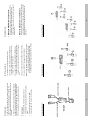
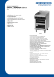
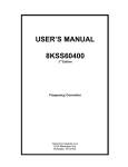
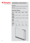
65M (210 ft.) (max.)
VGA, SVGA, Multisync
2 x HDB-15 Male
1 x HDB-15 Female
5 - 40o C
-20 - 60o C
0 - 80% RH, Non-condensing
Metal
0.165kg
10.4 x 9.8 x 2.4 (cm)
Cable length (output)
Signal Type
Video Input Connectors
Video Output Connectors
Operating Temperature
Storage Temperature
Humidity
Housing
Weight
Dimensions (L x W x H)
-4-
AC 9V, 100mA (max.)
Specification
Power consumption
Function
Specifications
-5-
The direct vendor makes no warranty or representation,
expressed, implied, or statutory with respect to the contents or
use of this documentation, and especially disclaims its quality,
performance, merchantability, or fitness for any particular
purpose. The direct vendor also reserves the right to revise or
update the device or documentation without obligation to notify
any individual or entity of such revisions, or update. For further
inquiries, please contact your direct vendor.
IN NO EVENT SHALL THE DIRECT VENDOR’S LIABILITY
FOR DIRECT, INDIRECT, SPECIAL, INCIDENTAL, OR
CONSEQUENTIAL DAMAGES RESULTING FROM THE USE
OF THE PRODUCT, DISK, OR ITS DOCUMENTATION
EXCEED THE PRICE PAID FOR THE PRODUCT.
Limited Warranty
WARNING!!! This equipment generates, uses and can radiate
radio frequency energy and, if not installed and used in
accordance with the instruction manual, may cause interference
to radio communications. This equipment has been tested and
found to comply with the limits for a Class A computing device
pursuant to Subpart J of Part 15 of the FCC Rules, which are
designed to provide reasonable protection against such
interference when operated in a commercial environment.
Operation of this equipment in a residential area is likely to
cause interference, in which case the user, at his own expense,
will be required to take whatever measures may be required to
correct the interference.
Radio & TV Interference
All brand names and trademarks are the registered property of their respective owners.
© Copyright 1997 ATEN® International Co., Ltd.
Manual Part No. PAPE-1112-100
Printed in Taiwan 07/1997
If anything is damaged or missing, contact your dealer.
M 1 User Manual
M 1 DC 9V Power Adapter
M 1 VS-201 Video Auto Switch
This package contains:
Read this manual thoroughly and follow the installation and
operation procedures carefully to prevent any damage to the
unit, and/or any of the devices connected to it.
VS-201
User Manual
Video Auto Switch
Connection Example 1:
-1-
M Daisy-chainable to VS-104 and VS-108 switches.
M Extends video signals up to 210 feet (65M).
M Switch setting to automatically select the incoming video
signal.
M Suitable for SVGA, VGA and multisync monitors.
Features
A slide switch sets the priority for the incoming video signals for
display on the monitor, and the VS-201 automatically selects the
proper input signal for its output port. Both features make the
VS-201 an excellent choice for educational environments.
1. Prioritize the input signal with the slide switch.
The VS-201 Video Auto Switch is an automatic video switch that
is ideal for monitors using analog signals. In addition, the
VS-201 boosts signals, allowing long distance transmission of up
to 210 feet.
Connection Example 2:
-2-
Note: The VS-201 detects input signals by checking the H sync.
In order for it to detect the input signals properly, you
must set the Video Off Method (in the computer BIOS
Power Management settings), to Black Screen (or similar).
5. Power on the VS-201 by plugging in its AC adapter.
4. Plug your monitor’s cable into the VS-201’s Video Out port.
3. Use a VGA cable with high density DB-15 Male/Female
connectors to connect a remote video signal (from another
computer or another video switch) to the VS-201’s Remote
port.
2. Use a VGA cable with high density DB-15 Male/Female
connectors to connect the video output port of your Local
computer to the VS-201’s Local port.
Installation
Overview
Connection Example 3:
-3-
Normally, the local signal is sent to the output port. When the
remote signal is detected, its LED illuminates and the VS-201
automatically switches to transmit the remote signal to the
output port.
M When the Slide Switch is set to Remote
Normally, the remote signal is sent to the output port. When
the local signal is detected, its LED illuminates and the
VS-201 automatically switches to transmit the local signal to
the output port.
M When the Slide Switch is set to Local:
Operation