1
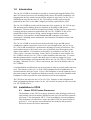
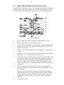
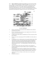
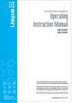
Film-Tech
The information contained in this Adobe Acrobat pdf
file is provided at your own risk and good judgment.
These manuals are designed to facilitate the
exchange of information related to cinema
projection and film handling, with no warranties nor
obligations from the authors, for qualified field
service engineers.
If you are not a qualified technician, please make no
adjustments to anything you may read about in these
Adobe manual downloads.
www.film-tech.com
Installation Instructions
For
Cat. No. 222SR/A Module
CP65 and CP55
Film Sound Processors
Dolby Laboratories Incorporated
U.S.A. 100 Potrero Avenue, San Francisco, CA 94103
Tel: 415-558-0200; Fax: 415-863-1373
U.K. Wootton Bassett, Wiltshire SN4 8QJ
Tel: (44) 1793-842100; Fax: (44) 1793-842101
Web: www.dolby.com
DISCLAIMER OF WARRANTIES: Equipment manufactured by Dolby Laboratories is warranted against defects in materials and
workmanship for a period of one year from the date of purchase. All warranties, conditions or other terms implied by statute are
excluded to the fullest extent allowed by law.
LIMITATION OF LIABILITY: It is understood and agreed that Dolby Laboratories’ liability whether in contract, in tort, under any
warranty, in negligence or otherwise shall not exceed the cost of repair or replacement of the defective components and under no
circumstances shall Dolby Laboratories be liable for incidental, special, direct, indirect or consequential damages (including but not
limited to damage to software or recorded audio or visual material), or loss of use, revenue or profit even if Dolby Laboratories or its
agents have been advised, orally or in writing, of the possibility of such damages.
Dolby and the double-D symbol are registered trademarks of Dolby Laboratories.
©1998 Dolby Laboratories Inc. All rights reserved
ISSUE 2
S98/10480/12245
Dolby Part No. 91383
-2-
1.0
Introduction
The Cat. No. 222SR/A card makes it possible to economically upgrade Dolby CP65
and CP55 cinema processors for decoding Dolby Stereo SR optical soundtracks. By
plugging into the slot usually occupied by the original A-type-only Cat. No. 222, it
eliminates the need for the two Cat. No. 350 cards previously required for SR
playback by the CP65, or the SRA5 adapter previously required by the CP55.
The Cat. No. 222SR/A provides all the functions of the regular Cat. No. 222 (A-type
NR, metering and switching) plus two channels of decoding for SR optical
soundtracks. Because it has been designed specifically for this purpose as opposed to
recording and post production applications, the Cat. No. 222SR/A is able to use
simplified circuitry and space-saving, custom-designed surface mount ICs.
Nevertheless, it incorporates all the fundamental SR techniques of its studio
counterparts, including action substitution, anti-saturation, modulation control and
spectral skewing.
The Cat. No. 222SR/A card will correctly decode both A-type and SR optical
soundtracks without compromise, however for special applications, the use of Cat.
No. 350s for SR decoding has a performance advantage in terms of headroom. This
extra headroom may be necessary in the case of playback of an SR magnetic print
master from a dubber. For instances such as this it is preferable to use the Cat. No.
350s even for a one-time screening. In the CP65 it is possible to have both the Cat.
No. 222SR/A and two Cat. No. 350s (or 300s) installed at the same time. To ensure
that the optimum choice is made when both types of cards are plugged in, logic
circuits on the backplane will automatically choose the Cat. No. 350s (or 300's) for SR
decoding. When the Cat. No. 350s are not present, the CP65 will default to the Cat.
No. 222SR/A
Certain backplane modifications may be necessary in order to properly utilize this new
card. The current revision (rev 3) of the CP65 backplane has been updated for the
card and includes the logic circuit. If your CP65 backplane is not the updated version
then some jumpers and a small board with the necessary circuit can be installed on the
backplane in order to provide the same functions as the newer backplane.
The CP55 does not allow the use of Cat. No. 350s. Jumpers on the backplane and
diode programming changes on the Cat. No. 243 card are necessary in order to use the
Cat. No. 222SR/A card.
2.0
Installation in CP65
2.1
Newer CP65 Cinema Processors
The backplane of the CP65 was factory updated to take advantage of this new
card starting with serial number 504989 onwards (in USA) and 5036 onwards
(in Europe). The designation "REV 3" has been added to current backplanes.
This designator is located above and to the right of TB5, the optical input for
projector 1. If it is present, no modifications are needed to the processor.
Proceed to Section 4 of these instructions.
-3-
2.2
Early CP65 Cinema Processors
If the backplane is not Rev. 3 or later then a small add-on board, the Cat. No.
565, must be installed on the backplane along with a wire jumper. The board
has two LED indicators; one green, the other red. These LEDs indicate which
card(s) will be used for decoding SR film sound tracks. The green LED will
light if Cat. No. 350s (or 300s) are installed. The red LED will light if they are
not present.
1.
Disconnect AC mains power to the CP65 by pulling out the plug
located at the rear of the power supply.
2.
Locate IC1 (see figure below). It is marked "DG211" and is located
above and to the left of the edge connector for the Cat. No. 222. With
a small screwdriver or an IC puller, carefully remove the IC from the
socket. It will not be used again and may be discarded.
3.
Locate the bottom lead of R38 and solder a jumper (supplied) between
this point and pin 16 of the Cat. No. 222 edge connector. Use care in
soldering to avoid splashes that can cause short circuits.
4.
Unsolder R25 from the backplane. Use solder wick or a solder sucker
to remove the excess solder and clear the holes.
CP65 Backplane (Below Revision 3)
-4-
5.
Remove the protective foam from connector J1 on the Cat. No. 565
adapter board to expose the pins. Carefully plug connector J1 into the
backplane socket that held IC1 and at the same time, insert the nylon
standoff into the hole in the backplane. Make sure to line up all of
the J1 pins with the IC1 socket before pressing the adapter board
into place. The pins can be easily broken.
6.
Solder the three wires from the Cat. No. 565 adapter board to the
following points:
Wire
Solder To
Green
Left hole where R25 was mounted
White
Right hole where R25 was mounted
Blue
Pin C of the Cat. No. 222 edge connector
CP65 Backplane With Cat. No. 565 Installed
7.
Proceed to Section 4.
-5-
3.0
Installation in CP55
1.
On the CP55 backplane, solder a wire jumper (provided) between pin FF of
the Cat. No. 243 edge connector (top right pin) and pin 16 of the Cat. No. 222
edge connector (top left pin). Use care in soldering to avoid splashes that can
cause short circuits.
The next steps depend on what modifications (if any) have been performed on the Cat.
No. 243 board in the past. Perform one of the three choices below.
3.1
Model SRA5 Not Installed
2.
If a Model SRA5 is not installed in the system and the Cat. No. 243 has
not been modified for this, remove diodes D29 and D33 from the F1
line of diodes.
D24
D33
D30
D29
Cat. No. 243 Board
3.
Using solder wick or a solder sucker, clean out the left hole above D24
in the F0 line so that a new diode lead can be inserted and soldered.
Add a new diode between this hole and the banded end of D30 (the
diode above and to the left of D29) with the banded end of the new
diode connected to D30. Use shrink tubing to avoid shorts with other
components.
4.
Since the function of the front panel 03 button is now changed to
format 05 (Dolby Stereo SR), an adhesive label is included to re-label
the front panel.
Clean the area of the front door around the format selection buttons
with alcohol to remove any greasy film that may be present. Remove
the label backing material, carefully position the sticker,. and press it
onto the panel. Press it firmly over the entire area to ensure good
adhesion.
5.
Proceed to Section 4.
-6-
3.2
Model SRA5 Installed Using Non-Sync Inputs
If model SRA5 is installed using the early method of returning the signal from
the SRA5 to the CP55 non-sync inputs, perform the following steps. In this
case, the bottom front panel button, AUX, was used to select SR decoding.
D24
D30
D33
D29
Cat. No. 243 Board
2.
Remove diodes D61, D64, D65, D66 and D72 from the F7 line.
3.
Remove diodes D29 and D33 from the F1 line.
4.
Add a diode to location D67. This will restore the bottom front panel
button for use in selecting a digital film format when the CP55 AUX
inputs are connected.
5.
Remove any wires connecting the CP55 and SRA5 (for either audio or
control).
6.
If needed, connect the non-sync source to the CP55 non-sync terminals
(TB1, pins 10, 11, 12) and check the non-sync level.
7.
Using solder wick or a solder sucker, clean out the left hole above D24
in the F0 line so that a new diode lead can be inserted and soldered.
Add a new diode between this hole and the banded end of D30 (the
diode above and to the left of D29) with the banded end of the new
diode connected to D30. Use shrink tubing to avoid shorts with other
components.
8.
Since the function of the front panel 03 button is now changed to
format 05 (Dolby Stereo SR), an adhesive label is included to re-label
the front panel.
Clean the area of the front door around the format selection buttons
with alcohol to remove any greasy film that may be present. Remove
the label backing material, carefully position the sticker, and press it
onto the panel. Press it firmly over the entire area to ensure good
adhesion.
9.
Proceed to Section 4.
-7-
3.3
Model SRA5 Installed Using Wiring to the Cat. No. 222
If Model SRA5 is installed using the newer method of returning the signal
from the SRA5 to the Cat. No. 222 edge connector with soldered wires,
perform the following steps. In this case, the front panel button labeled 03
(second button down from the top) was used to select SR decoding. After this
modification, this button will continue to be used to select SR decoding.
D24
D67
Cat. No. 243 Board
2.
Remove the diode connected between the middle hole above D24 to
the banded end of D30.
3.
Remove the diode connected between the right hole above D24 to the
square pad of the D29 location.
4.
Confirm that no other diode is installed in the F7 line except one in the
D67 location.
5.
Remove any wires connecting the CP55 and SRA5 (for either audio or
control).
6.
Using solder wick or a solder sucker, clean out the left hole above D24
in the F0 line so that a new diode lead can be inserted and soldered.
Add a new diode between this hole and the banded end of D30 (the
diode above and to the left of D29) with the banded end of the new
diode connected to D30. Use shrink tubing to avoid shorts with other
components.
7.
Since the function of the front panel 03 button is now changed to
format 05 (Dolby Stereo SR), an adhesive label is included to re-label
the front panel.
Clean the area of the front door around the format selection buttons
with alcohol to remove any greasy film that may be present. Remove
the label backing material, carefully position the sticker, and press it
onto the panel. Press it firmly over the entire area to ensure good
adhesion.
8.
Proceed to Section 4.
-8-
3.4
Cat. No. 243A installed in Model CP55
The following modifications are required to enable the Cat. No. 222SR/A to
function correctly in a Model CP55 using a Cat. No. 243A.
D24
D33
D30
D29
1.
Using solder wick or a solder sucker, remove diode J5
2.
Remove diode D81
3.
Remove diode D82
4
Add a 1N4148 diode (as removed in step 1) in the position shown. The
cathode (banded end) must connect to the square copper circuit pad.
-9-
4.0
Alignment of the Cat. No. 222SR/A
1.
Verify that the AC mains is not connected to the cinema processor. Open the
front panel of the processor and remove the existing Cat. No. 222 module.
2.
If this is a CP65 installation then remove the two Cat. No. 350s.
3.
Plug in the Cat. No. 222SR/A card into the slot that held the Cat. No. 222
module.
4.
Reconnect AC mains power to the cinema processor.
Note: The Cat. No. 222SR/A LED Dolby level meters behave slightly
differently than those on the Cat. No. 222. On the Cat. No. 222, the lowest
LEDs (red) are on when the signal level is below Dolby level. This means that
in the absence of any signal, the red LEDs will be on. The red LEDs on the
new Cat. No. 222SR/A card will light for signals which are within
approximately 10 dB of Dolby level and will be off for signals well below
Dolby level. This difference in operation is normal.
5.
Select format 01 (mono) on the front panel of the processor and thread a loop
of Cat. No. 69 Dolby tone test film in the projector. Start the projector and
adjust the left and right gain controls for the correct projector on the Cat. No.
240 optical preamp card to obtain Dolby level (both green LEDs on equally).
If present, repeat the above steps for the second projector. If a spare Cat. No.
240 optical preamp card is present, repeat the above steps to set the correct
gain adjustments for this card.
This completes the installation of the Cat. No. 222SR/A.