1
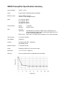
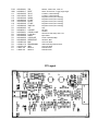
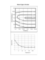
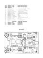
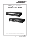
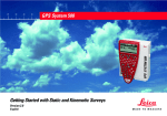
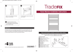
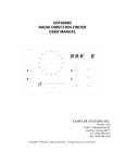
MODEL
SR550/552
Voltage Pre-amplifier
1290-D Reamwood Avenue
Sunnyvale, CA 94089 U.S.A.
Phone: (408) 744-9040, Fax: (408) 744-9049
Email: [email protected] • www.thinkSRS.com
Copyright © 1999, 2001
Stanford Research Systems, Inc.
All Rights Reserved
Rev. 2.6 (08/2001)
Voltage Pre-amplifier
manual
Stanford Research Systems
SR550 Preamplifier Specifications Summary
Ω
!"#
!$!
%
&'(!)√*+
*+
,'!)√*+
*+
&!)√*+
*+
-.
/
"
0
"20
5
$$$
")&
9:718
!
1
34
*+
6
..""&718
#.
.
#'#.
!
!
5
'9#718
.
'
5
6
.
;*+1*+
5
.
)</
=
6(Ω
4
=
>!
1
1
:
."718#
'
'&?@&'?@'?$'
A
.
=.
1
'
OPERATING INSTRUCTIONS
-"!
:86
")&18
9:18'-"
#.! '
A
8
$
"
1
'
:
"#
3
'
6
"'A18
$
:"B86:
18'4
C#
'
C$
.
3
'A18$
:=AB"
"'
CONNECTING THE SR550
-6="
618'
$
C
'-18
6'
.
18
$
"4=8
418
'
-6
4
##18'-18
684'
-"6
4
18#
'-
$6$
$
684$
'-
Ω$'-
.='-
!
# !
1'-
#
&!
1!
"'-=!B"7=69
#8
#
'%
#
8
.18D#
'
USING THE SR550 WITH THE SR510/530
-")18
"
1
'-$
#
$"
#
18'
-#
#.188
.
#.
18
'%=-
.#
.#..'A
#.$"
'
-
"$$$'-
.18
+8
.
#'
#$8
'-
+
'
":86:
"
:
DYN RES FS Sensitivity SR550 Gain
7=A
E!
!
!
F!
E!
!
!
F!
*5*
(
Eµ!
µ!
µ!
Fµ!
%="
,
A"$
#.
! '
-$$!#
18'"
#.
!$#.#
1!'
$
"
D*D
'6$
8&
D5D
#
!':8
#
#
'
USING THE SR550 WITH SRS DSP LOCK-INS
-".9:18'
-9:18%=-
'-
'
#.'
-"6/*+1*+'
186/
#*+'C
*+."'
COMMON MODE ADJUST
-2"
2.
'-/"
.$
#$
.
.8
2$
.C.
'-
.
1
/"
18
.
'6.
18"BB"B%/B%:G-'
6.
!
6
4
"'/1"
.
6'-18
!
2"'%
"684'6218#.
;'62/"
"+18'=
"$
.1
3<
'=
18$"
#
'
THE SR550 WITHOUT A LOCK-IN
-"
.':
3
'
Pin
(
>
H
Voltage
!
!
8!
5
5
Current
6
6
6
6#
C':>
H
'6
'-
'
5&
$
,
'
5&
,
'
PARTS LIST
REF.
/
/
/&
/,
/
/(
/>
/H
/3
/
/
9
9
I
:
:
:/
K
"
"
"&
",
"
"(
">
"H
"3
"
"
"
"&
",
"
"(
">
"H
"3
"
"
"
"&
",
"
"(
">
"H
"3
"&
"&
"&
SRS part#
8,83
8&8
8&8
88>
88>
88>
8&8
8&8
88>
8(8
8(8
&88&&
&88&&
8,8(
,8&,8,,
,88,,
>8338>
&8,8&&
,83&8,
,8,>8,
,8,>8,
,8>8,
,8>8,
,8(38,H
,8(38,H
,8,8,>
,88,
,88,
,8(8,
,88,
,8(8,
,8H8,
,8(H8,H
,8(H8,H
,8H8,>
,8,8,>
,8&8,
,8&8,
,8H8,
,8H8,
,83&8,>
,8&8,
,8>8,
,8&(8,>
,8&(8,>
,8>8,H
,8>8,H
,838,>
,8&8,>
,838,
VALUE
'G
G
G
'G
'G
'G
,>G
,>G
'G
'G
'G
"B9
5"BB%
3:%9
J
"8
%(,
('J
'
'
'J
'J
(
(
,J
>J
,J
,>
3HH
3HH
&
J
J
,>
,>
,33
,'&J
'J
'J
'J
'J
(
DESCRIPTION
Capacitor, Electrolytic, 50V, 20%, Rad
Capacitor, Electrolytic, 16V, 20%, Rad
Capacitor, Electrolytic, 16V, 20%, Rad
Capacitor, Tantalum, 35V, 20%, Rad
Capacitor, Tantalum, 35V, 20%, Rad
Capacitor, Tantalum, 35V, 20%, Rad
Capacitor, Electrolytic, 25V, 20%, Rad
Capacitor, Electrolytic, 25V, 20%, Rad
Capacitor, Tantalum, 35V, 20%, Rad
Cap, Stacked Metal Film 50V 5% -40/+85c
Cap, Stacked Metal Film 50V 5% -40/+85c
LED, T1 Package
LED, T1 Package
Connector, D-Sub, Right Angle PC, Female
Pot, Multi-Turn, Side Adjust
Pot, Multi-Turn Trim, 3/8" Square Top Ad
Printed Circuit Board
Transistor, TO-71 Package
Resistor, Carbon Film, 1/4W, 5%
Resistor, Carbon Film, 1/4W, 5%
Resistor, Carbon Film, 1/4W, 5%
Resistor, Carbon Film, 1/4W, 5%
Resistor, Carbon Film, 1/4W, 5%
Resistor, Metal Film, 1/8W, 0.1%, 25ppm
Resistor, Metal Film, 1/8W, 0.1%, 25ppm
Resistor, Metal Film, 1/8W, 1%, 50PPM
Resistor, Carbon Film, 1/4W, 5%
Resistor, Carbon Film, 1/4W, 5%
Resistor, Carbon Film, 1/4W, 5%
Resistor, Carbon Film, 1/4W, 5%
Resistor, Carbon Film, 1/4W, 5%
Resistor, Carbon Film, 1/4W, 5%
Resistor, Metal Film, 1/8W, 0.1%, 25ppm
Resistor, Metal Film, 1/8W, 0.1%, 25ppm
Resistor, Metal Film, 1/8W, 1%, 50PPM
Resistor, Metal Film, 1/8W, 1%, 50PPM
Resistor, Carbon Film, 1/4W, 5%
Resistor, Carbon Film, 1/4W, 5%
Resistor, Carbon Film, 1/4W, 5%
Resistor, Carbon Film, 1/4W, 5%
Resistor, Metal Film, 1/8W, 1%, 50PPM
Resistor, Carbon Film, 1/4W, 5%
Resistor, Carbon Comp, 1/2W, 5%
Resistor, Metal Film, 1/8W, 1%, 50PPM
Resistor, Metal Film, 1/8W, 1%, 50PPM
Resistor, Metal Film, 1/8W, 0.1%, 25ppm
Resistor, Metal Film, 1/8W, 0.1%, 25ppm
Resistor, Metal Film, 1/8W, 1%, 50PPM
Resistor, Metal Film, 1/8W, 1%, 50PPM
Resistor, Carbon Film, 1/4W, 5%
"&&
A
G
G
G&
G,
G
G(
G>
L
L
L
L
L
L
L
L
L
L
,88,
88>
&8,8&
&8H8&
&83&8&,
&8(8&,
&8>(8&,
&8(8&,
&8&H8&,
88
8,&8
8>38&
88&
8,83
8,38
8HH8
8&8
8,8>
8>&8
>J
9:9>37
>H7
7&&3
7->
95
7->
>,*/&3
&)H?
,8,JB:
,8,@&)()
8),?M,
*BB,8,@),:
"==4%/
9438943)
%7
Z0
Z0
7-00097-720
7-00098-720
SR550-2
SR550-3
Resistor, Carbon Film, 1/4W, 5%
Switch, On-None-On, Toggle, Right Angle
Transistor, TO-92 Package
Transistor, TO-92 Package
Integrated Circuit (Thru-hole Pkg)
Integrated Circuit (Thru-hole Pkg)
Integrated Circuit (Thru-hole Pkg)
Integrated Circuit (Thru-hole Pkg)
Integrated Circuit (Thru-hole Pkg)
Lugs
Nut, Kep
Standoff
Wire #24 UL1007 Strip 1/4x1/4 Tin
Mylar Sheet
Screw, Flathead Phillips
Hardware, Misc.
Connector, BNC
Cable Assembly, Multiconductor
Connector, BNC
Fabricated Part
Fabricated Part
PC Layout
MODEL SR552
Voltage Pre-amplifier
manual
Stanford Research Systems
SR552 Preamplifier Specifications Summary
IInput Impedance
100 KΩ + 25 pF
Inputs
Single ended or differential (switch selectable)
Maximum Inputs
70 mV rms for overload
Damage threshold: 20 Vac, 50 Vdc
Noise
1.4 nV/√Hz at 1000 Hz
1.6 nV/√Hz at 100 Hz
2.5 nV/√Hz at 10 Hz
(all figures are Typical)
Common Mode
Range:
Rejection:
Gain
10,20,50,100
SR510/530
DSP Lock-Ins
1 Volt peak
100 dB at 100 Hz
Automatically set by SR510 or SR530 Lock-In depending on
sensitivity and dynamic reserve. Sensitivity ranges from 10 nV to 200
mV full scale (with expand off).
Note: Lock-in readings must be divided by 10.
Gain is set to 100. Divide lock-in recordings by 100 for correct
amplitude.
Gain Accuracy
2% (2 Hz to 100 kHz)
Gain Stability
200 ppm/°C
Outputs
(A) single ended (600Ω impedance)
(B) shielded ground
Maximum Output
10 Volts peak
Power
Supplied by SRS Lock-In via control cable.
Mechanical
Size
1.3" X 3.0" X 5.1"
Weight 1 lb.
Warranty
One year parts and labor on materials and workmanship.
Noise Figure Contour
OPERATING INSTRUCTIONS
The SR552 Voltage Pre-Amplifier is designed to
be used with either the SR510/530 lock-ins as
well as the newer DSP lock-ins. The SR552
reduces the input noise and extends the full
scale sensitivity to 10 nV (without expand).
When used as a remote pre-amplifier, the
SR552 can eliminate the effects of noise pickup
on long signal cables.
Power and control are supplied to the SR552 via
the 9 pin cable which is supplied with the unit.
Attach one end of the cable to the connector on
the rear of the SR552. With the lock-in power
off, connect the other end of the cable to the
PRE-AMP connector on the rear of lock-in. Both
ends of the cable are equivalent. If a longer
cable is required, any standard 9 pin cable will
suffice since all connections are straight
through. When the lock-in power is on, the
POWER indicator on the SR552 will light.
The SR552 (A) and (B) Inputs should now be
used as the lock-in voltage inputs. The input
switch selects single ended, (A), or differential,
(A-B), operation. The input impedance is 100
kΩ, 25 pF. The connector shields are isolated
from the chassis ground by 10 Ohms. These
inputs are protected to 100 Vdc but the ac input
should never exceed 10 V peak. The maximum
input before overload is 70 mV rms. The
OVERLOAD indicator will light whenever the
pre-amplifier overloads. Note that overloads
that occur after the pre-amplifier are indicated by
the lock-in's overload indicator.
USING THE SR550 WITH THE SR510/530
The SR510/530 lock-ins sense the presence of
the SR552 through the power cable and takes it
into account when setting the gain of its own
amplifiers. Thus, to obtain the correct overall
gain, the SR552 output must be connected to
the voltage inputs of the lock-in.
CONNECTING THE SR552
The (A) Output of the SR552 should be
connected to the (A) Input of the lock-in. For
most applications, this single connection will be
adequate. The lock-in Input Selector should be
set to (A). For situations where there may be
noise pick-up on this cable, it is better to connect
the SR552 (B) Output (shielded pre-amp
ground) to the (B) Input of the lock-in as well.
The (A) and (B) cables should be twisted
together to prevent inductive pick-up. The lockin Input Selector should then be set to (A-B).
The overall sensitivity of the lock-in plus the preamplifier is displayed as the sensitivity on the
lock-in front panel. It is necessary to divide the
displayed sensitivity by 10.
The gain of the SR552 is 10, 20, 50, or 100.
The gain is controlled by the lock-in and is set to
maximize the pre-amplifier gain while
maintaining the selected dynamic reserve. For
most sensitivities, the pre-amplifier gain will be
100. The following table summarizes the gain
allocation.
SR552 Pre-Amplifier Front Panel and Rear Panel
DYN RES
FS Sensitivity SR552 Gain
LOW
20 db
> 50 mV
50 mV
20 mV
< 20 mV
10
20
50
100
USING THE SR552 WITH SRS DSP LOCK-INS
The SR552 is not sensed by the DSP lock-ins.
The DSP lock-in does NOT compensate for the
gain of the preamp. The gain of the preamp is
set to 10. Measurements made with the preamp
need to be divided by 100.
NORM
40 db
> 5 mV
5 mV
2 mV
< 2 mV
10
20
50
100
The SR552 is AC coupled from 1 Hz to 100 kHz.
Set the lock-in input to AC coupled since the
signal must be above 1 Hz. Frequencies below 1
Hz will not be detected by the SR552.
HIGH
60 db
> 500 µV
500 µV
200 µV
< 200 µV
10
20
50
100
When the SR552 is connected, the full scale
sensitivity can extend to 10 nV (no expand).
The 10, 20, 50 nV sensitivities can be reached
using the normal lock-in controls. If the SR552
is disconnected while the sensitivity is below 100
nV, the sensitivity will revert back to 100 nV.
From the computer interface, the presence of
the SR552 can be determined using the 'H'
command. Also, gain codes 1-3 are acceptable
in the 'G' command to set sensitivities below 100
nV. Pre-amplifier overloads are not detectable
via the computer interface.
COMMON MODE ADJUST
The common mode rejection of the SR552 is
adjusted by the small screw on the right side of
the enclosure. The CMR is set at the factory,
however, it may be necessary to re-adjust it,
particularly if there is one specific frequency
which is important. The easiest way to peak the
CMR is to use the internal oscillator of the lockin (or any signal generator). Apply a reference
signal to the lock-in REFERENCE INPUT.
Apply a 100 mV signal to both the (A) and (B)
inputs of the SR552. Check the SR552
connections by switching the input selector to
(A). The lock-in should read 100 mV (with the
phase adjusted on the SR510). Now switch the
SR552 to (A-B). Adjust the lock-in sensitivity to
obtain a 50% output. Adjust the CMR screw on
the SR552 to minimize the lock-in output. On
the SR510, it is necessary to check the output
when 90° of phase shift is added as well. On a
dual phase lock-in, use the R output to avoid
phase shifts.
The SR552 without a lock-in
The SR552 can be powered with an external
power supply. Power is applied through the 9
pin connector as described below.
Pin
1
2
6
7,8
Voltage
+20 V
+5 V
-20 V
Ground
Current
100 mA
10 mA
100 mA
All three voltages are required. Pins 7 and 8
should be tied together. All other pins should be
left open. The gain will be 100 in this
configuration. Grounding pin 3 will change the
gain to 50, and grounding pin 4 will change the
gain to 20. Grounding both pins 3 and 4 will
change the gain to 10.
PARTS LIST
REF.
C1
C2
C3
C4
C5
C6
C7
C8
C9
C 10
C 11
C 12
C 13
C 14
D1
D2
J1
P1
P2
PC1
Q1
R1
R2
R3
R6
R7
R8
R9
R 10
R 11
R 12
R 13
R 14
R 15
R 16
R 17
R 18
R 21
R 23
R 24
R 25
R 26
R 27
R 28
R 29
R 30
R 31
R 32
SRS part#
5-00040-509
5-00030-520
5-00030-520
5-00100-517
5-00100-517
5-00100-517
5-00044-509
5-00044-509
5-00100-517
5-00034-526
5-00034-526
5-00192-542
5-00008-501
5-00008-501
3-00011-303
3-00010-303
1-00014-160
4-00354-445
4-00353-441
7-00127-701
3-00231-328
4-00093-401
4-00047-401
4-00047-401
4-00356-407
4-00356-407
4-00141-407
4-00052-401
4-00052-401
4-00061-401
4-00082-401
4-00061-401
4-00021-401
4-00351-407
4-00351-407
4-00180-407
4-00141-407
4-00176-407
4-00193-407
4-00093-401
4-00107-402
4-00142-407
4-00142-407
4-00204-407
4-00204-407
4-00158-407
4-00178-407
4-00081-401
VALUE
1.0U
2200U
2200U
2.2U
2.2U
2.2U
47U
47U
2.2U
100U
100U
22U MIN
22P
22P
RED
GREEN
9 PIN D
20
100
SR552
MAT02-EH
6.2K
2.2
2.2
20
20
100
20
20
240K
470K
240K
1.0K
2.32K
2.32K
301
100
3.01K
499
6.2K
10
100K
100K
750
750
2.00K
3.83K
470
DESCRIPTION
Capacitor, Electrolytic, 50V, 20%, Rad
Capacitor, Electrolytic, 16V, 20%, Rad
Capacitor, Electrolytic, 16V, 20%, Rad
Capacitor, Tantalum, 35V, 20%, Rad
Capacitor, Tantalum, 35V, 20%, Rad
Capacitor, Tantalum, 35V, 20%, Rad
Capacitor, Electrolytic, 50V, 20%, Rad
Capacitor, Electrolytic, 50V, 20%, Rad
Capacitor, Tantalum, 35V, 20%, Rad
Capacitor, Electrolytic, 35V, 20%, Rad
Capacitor, Electrolytic, 35V, 20%, Rad
Cap, Mini Electrolytic, 50V, 20% Radial
Capacitor, Ceramic Disc, 50V, 10%, SL
Capacitor, Ceramic Disc, 50V, 10%, SL
LED, T1 Package
LED, T1 Package
Connector, D-Sub, Right Angle PC, Female
Pot, Multi-Turn, Side Adjust
Pot, Multi-Turn Trim, 3/8" Square Top Ad
Printed Circuit Board
Transistor, TO-78 Package
Resistor, Carbon Film, 1/4W, 5%
Resistor, Carbon Film, 1/4W, 5%
Resistor, Carbon Film, 1/4W, 5%
Resistor, Metal Film, 1/8W, 1%, 50PPM
Resistor, Metal Film, 1/8W, 1%, 50PPM
Resistor, Metal Film, 1/8W, 1%, 50PPM
Resistor, Carbon Film, 1/4W, 5%
Resistor, Carbon Film, 1/4W, 5%
Resistor, Carbon Film, 1/4W, 5%
Resistor, Carbon Film, 1/4W, 5%
Resistor, Carbon Film, 1/4W, 5%
Resistor, Carbon Film, 1/4W, 5%
Resistor, Metal Film, 1/8W, 1%, 50PPM
Resistor, Metal Film, 1/8W, 1%, 50PPM
Resistor, Metal Film, 1/8W, 1%, 50PPM
Resistor, Metal Film, 1/8W, 1%, 50PPM
Resistor, Metal Film, 1/8W, 1%, 50PPM
Resistor, Metal Film, 1/8W, 1%, 50PPM
Resistor, Carbon Film, 1/4W, 5%
Resistor, Carbon Comp, 1/2W, 5%
Resistor, Metal Film, 1/8W, 1%, 50PPM
Resistor, Metal Film, 1/8W, 1%, 50PPM
Resistor, Metal Film, 1/8W, 1%, 50PPM
Resistor, Metal Film, 1/8W, 1%, 50PPM
Resistor, Metal Film, 1/8W, 1%, 50PPM
Resistor, Metal Film, 1/8W, 1%, 50PPM
Resistor, Carbon Film, 1/4W, 5%
R 33
RU7A
RU7B
SW1
U1
U2
U3
U4
U5
U7
Z0
Z0
Z0
Z0
Z0
Z0
Z0
Z0
Z0
Z0
Z0
4-00082-401
4-00032-401
4-00032-401
2-00025-217
3-00124-325
3-00118-325
3-00193-340
8-00085-860
3-00076-340
3-00038-340
0-00025-005
0-00043-011
0-00079-031
0-00122-053
0-00140-009
0-00149-020
0-00188-000
1-00003-120
1-00041-170
1-00073-120
7-00098-720
Z0
7-00128-720
470K
100K
100K
SPDT
79L15
78L15
LM339
SR513 ASSY
DG211
74HC139
3/8"
4-40 KEP
4-40X3/16 M/F
2-1/4" #24
SHEET
4-40X1/4PF
SR552FOOT
BNC
DB9-DB9/MM
INSL
SR552-3
SR552-2
Resistor, Carbon Film, 1/4W, 5%
Resistor, Carbon Film, 1/4W, 5%
Resistor, Carbon Film, 1/4W, 5%
Switch, On-None-On, Toggle, Right Angle
Transistor, TO-92 Package
Transistor, TO-92 Package
Integrated Circuit (Thru-hole Pkg)
SRS sub assemblies
Integrated Circuit (Thru-hole Pkg)
Integrated Circuit (Thru-hole Pkg)
Lugs
Nut, Kep
Standoff
Wire #24 UL1007 Strip 1/4x1/4 Tin
Mylar Sheet
Screw, Flathead Phillips
Hardware, Misc.
Connector, BNC
Cable Assembly, Multiconductor
Connector, BNC
Fabricated Part
Fabricated Part
PC Layout