1
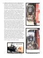
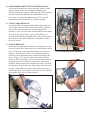
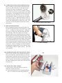
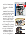
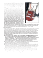
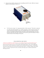
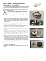
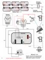
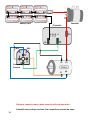
STQ EZ9 2001 PERFORMANCE ENHANCEMENT KIT
For EZGO NON-DCS Installation Instructions
We would like to thank you for purchasing our exclusive Motor & Controller Performance Enhancement
Kit. We take great pride in our products and feel certain that this kit will offer you many years of troublefree service. We ask that you take a moment to read these instructions completely before beginning your
installation. Familiarity with the parts and an understanding of the procedures will ensure that your installation
goes smoothly and safely. Additionally, it will give you an opportunity to determine if your cart might have
any damaged, corroded, or missing parts, which will need replacing prior to using your new Performance
Enhancement Kit.
ABOUT THIS PERFORMANCE ENHANCEMENT KIT
This Performance Enhancement Kit is designed specifically for 1994.5-Present EZGO Non-DCS 36 and 48
volt electric golf carts. If you are unsure of your golf cart type, please see our catalog or contact our technical
department, toll free at 1-888-444-9994, or online at www.buggiesunlimited.com. During the installation of this
kit you will be upgrading three major electrical components from your golf cart, with three high performance
components in our STQ EZ9 2001 Performance Enhancement Kit. These parts are: the motor, the speed
controller, and the solenoid. All of your electrical connections will be made between these components and
either the battery group or a device called a forward/reverse switch. You should allow about 4 hours for
installation.
PARTS INCLUDED IN OUR KIT
1)
2)
3)
4)
Electric motor (per application).
500 amp speed controller 36/48 volt.
Electric solenoid (36/48 V high performance).
4 Gauge Cable Kit (Non-DCS), including:
a) 3 red coded cables.
b) 1 blue coded cable.
c) 1 white coded cable.
d) 1 orange coded cable.
e) 1 green coded cable.
f) 1 black coded cable.
g) 5 red/black coded cables.
5) Bridge Resistor (250 ohm) and diode.
6) Hardware kit.
7) 2 Contacts, F&R Switch
C
1
Contacts
TOOLS AND MATERIALS REQUIRED TO INSTALL KIT
1) SAE socket set, with ratchet
and 3” and 6” extensions.
2) 8mm deep socket
3) SAE combination wrench set.
4) 1/2” wrench (extra).
5) #2 Phillips and Flat Tip screwdrivers.
6) Wire cutters.
7) T15 Torx driver.
8) Heavy weight grease.
9) Wire Terminal Crimper
10) Safety Goggles/Glasses
ADDITIONAL TOOLS WHICH MAKE THE JOB BETTER AND FASTER
1)
2)
3)
4)
5)
Battery Carrying Strap. Part # BT8001.
Battery Terminal Protector Spray. Part # BT60512.
Battery Terminal Re-facer. Part # BU6002.
Electronic Multi-meter. Part # BU6001.
Small Box of Baking Soda. Local store purchase.
BT8001
BT60512
BU6002
BU6001
A NOTE BEFORE STARTING
Throughout this installation, we will be discussing the connection of #4 heavy gauge cables to several different
electrical components. Some cables will be attached to THREADED LUGS or “posts”, and others will be
attached to FLAT Buss BARS. An understanding of each of these cable connections is important. Let’s first
cover the THREADED LUGS. You will notice these lugs utilize a set of double nuts to hold the cable terminal
firmly in place. Typically, a cable terminal and a washer will be sandwiched between these two nuts. This
configuration is deliberate, and care should be given to properly removing or installing these nuts. An open-end
wrench of the appropriate size should be held on the bottom nut while another wrench or socket is used on the
top nut to either loosen or tighten this connection. The use of opposing wrenches relieves the threaded lug of
excessive stress and eliminates the possibility of damaging the seals at the base of these lugs. Failure to use the
opposing wrench technique on double-nutted lugs can permanently damage the component. You will also want
to use the opposing wrench technique when making connections at the FLAT Buss BARS, but care should also
be given to avoid twisting or bending the bars. Again, these seals at the base of the connection points are fragile
and subject to damage if handled improperly. Seal damage at these electrical contact points will void the
warranty for that component.
2
INSTALLATION
1) SEAT CUSHION REMOVAL: Remove the seat
assembly by lifting the side grab handles. The cushion
hinges to the front of the cart, and will simply lift off
when it’s in the vertical position.
2) ACCESS PANEL REMOVAL: Remove the black
plastic rear access panel located behind the seat, which
is secured using five T15 Torx head screws.
1
3) BATTERY REMOVAL: There are two things to take
note of here: Battery placement and wiring layout.
NOTE: Battery acid can be very damaging... wear
rubber gloves, eye protection, and old clothes.
Work in a well-ventilated and appropriate area
for the task. Battery residue can stain concrete.
Observe the position and orientation of the battery
group, as you will want to reinstall all the batteries
in the same manner. Failure to orient the batteries
correctly can leave some wires too short or too long
for their intended purpose. Hint: As you remove
and set the batteries aside, place them in a grouping
just as they appeared in the battery tray of your cart.
This will leave no doubt as to their original position.
Also take note of your battery cables. You’ll see that 2
the batteries are always connected to each other in a
series configuration… that is “positive” to “negative”
to “positive” to “negative” and so on through all six
batteries. Confirm that your battery cables appear like
those in the wiring diagram, and remove all existing
wiring from the batteries. There will be other smaller
wires connected to some of the batteries on your cart.
Write down the location of those smaller wires, as you
will be reinstalling them in those same locations after
you have completed the installation of the Performance
Enhancement kit. Hint: Labeling the wires with a
small piece of masking tape will go a long way in
avoiding confusion upon reinstallation. Once you have
made the above notations and removed the cables and
wires, you can release the batteries by using a 1/2” or
9/16” socket to remove the two nuts and washers on
the bolts of the hold-down plate centered in the battery
grouping. Note: Use care in lifting the batteries from
the cart…they are very heavy. A battery carrying strap
makes this job much easier.
3
3
l
ne
Pa
ss
ce
Ac
4
3
5
2
6
1
4) SPEED CONTROLLER AND SOLENOID REMOVAL:
Directly below the passenger’s seat you will find a black
plastic cover… this is called the controller cover. The cover
is secured using four hex head machine bolts. Remove these
bolts using a 3/8” socket with the appropriate extension.
Underneath the cover you will notice the speed controller and
the solenoid. The speed controller is the small metal box and
the solenoid is the cylindrical device mounted on top of the
controller. Begin the removal of these components by first
discharging the speed controller. Using a standard screwdriver
bridge the terminals marked “B-” and “B+”. You may see
or hear a small spark and this is normal, and is an indicator
that the capacitors inside the speed controller have been
discharged. Let’s begin with the SOLENOID (the cylindrical
device). You will notice it has two large lugs and two smaller
lugs. You will be replacing all the cables on the large lugs
with cables from our new Performance Enhancement Kit,
but the wires attached to each of the smaller lugs will be kept
and reattached to the new solenoid. Don’t forget to use the
opposing wrench technique when removing these wires and
cables. Moving on to the SPEED CONTROLLER. You will
notice it has three large flat buss bars and one 6-pin Molex
connector. The Molex connector may have a small tab which
needs to be depressed in order to pull the connector from the
speed controller (4c). Do not pull the Molex connector by the
wires… grip the body of the connector and wiggle it back and
forth as you pull outward. Just like on the solenoid, you will
be replacing the large cables on the speed controller with new
cables from our STQ EZ9 2001 Performance Enhancement
Kit, but the smaller wires in the 6-pin Molex connector
will be retained and reinstalled on the new speed controller.
Remember to use the opposing wrench technique, and to avoid
twisting or bending of the buss bars. Once all of the wires
and cables have been disconnected, release the mounting
hardware of the controller and the solenoid and remove those
components from the cart. Retain the 3 metric bolts, which
hold the controller, as they will be used later.
Controller
Cover
4a. Controller Cover (On)
Solenoid
Molex Connector
Contr
oller
4c. 6-Pin Molex Connector Removal
4
4b. Controller Cover (Off)
5) FORWARD/REVERSE SWITCH WIRE REMOVAL:
Locate the forward/reverse switch assembly, which is found
directly in front of the speed controller mounting area.
Remove all four heavy gauge cables from the switch assembly
and retain the factory hardware for reinstallation of your
new cables. See the wiring diagram (pg. 12) for a visual
representation of the forward/reverse switch assembly.
6) FINAL CABLE REMOVAL:
You will find four (4) large threaded electrical lugs on the case
of the motor, with one cable connected to each lug. Remove
these cables, remembering to use the opposing wrench
technique. Once you have removed the cables from the motor,
all of the heavy gauge cables in your cart should now be
disconnected from their mounting points, and you may remove
them from the cart, while taking note of the paths in which
they were routed.
7) MOTOR REMOVAL:
Before removing the motor, clean the surrounding area of any
excessive mud or dirt, which may have accumulated on nearby
parts. We want to ensure that internal parts stay as clean as
possible. Once the area is clean, you will notice three hex
head bolts on the differential case, which bolt through to the
motor. Using a 7/16” socket, remove these bolts to release
the motor from the housing. If your cart has a cable-retaining
loop fastened to one of the motor mount bolts, release that
bolt first, and then remove the remaining two bolts. Carefully
pull the motor from the housing. Some gentle back and forth
pressure, while pulling the motor, should allow the motor to
slide off the shaft. Use caution, as the motor is heavy and will
drop quickly once it is free from the shaft.
5. Forward & Reverse Assembly
Mot
or
6. Opposing Wrench Technique
Di
f
Ca fere
nt
se
i
al
7. Gentle Back and Forth Pressure To Remove Motor
5
8) COMPONENT INSTALLATION PREPARATION:
Before installing our Performance Enhancement Kit
in your cart, take a little time to clean the areas now
exposed by the removed components. The motor
mount may have some grit or dirt around the opening
of the mount. A moist rag or small brush can be used to
clean that area. Avoid letting dirt fall into the housing.
The battery trays may have dirt, leaves, or corrosion,
which should be cleaned. For instruction on cleaning
corrosion, see step 12. While the mounting surface of
the controller should be quite clean, inspect it and wipe
it down with a damp cloth to remove dirt or film. This
area acts as a heat sink and dirt will interfere with its
performance.
9) MOTOR INSTALLATION:
Before mounting the motor, lubricate the splines, but
not the end of the motor shaft with quality heavy-weight
grease… available at any auto parts store. Lifting the
new motor up, slide it onto the shaft inside the motor
mount housing. With some gentle back and forth
movement and pressure toward the housing, the motor
should mount up to the housing with little effort. Align
the mounting holes of the housing and the mounting holes
of the motor by rotating the motor slightly. When aligned
properly, the threaded electrical lugs of the new motor
will be on bottom and the mounting bolts can be inserted.
Don’t forget to reinstall your cable-retaining loop, if your
cart has one. Observe a rotating or crisscross pattern as
you tighten the mounting bolts, to ensure that the motor
is not binding or stressed. Tighten securely… but avoid
over tightening.
10) CONTROLLER AND SOLENOID INSTALLATION:
In the kit you will find a new solenoid that mounts on
back of the controller. Install the diode across the two
small terminals. Install the resistor across the two large
terminals. Install the fuse on the number one battery
positive teminal. After all cables are installed connect
the main soleniod positive cable to the open end of the
fuse Figure 10.
11) CONNECTING THE CABLES:
It is now time to connect the cables to your new
controller, solenoid, and motor.
a) Locate the small resistor wire from the hardware
pack. It is a short wire with a ring terminal on
6
8. Clean the Motor Mount Area
9. Motor Installed
10.
b)
c)
d)
e)
f)
each end. This wire will jumper across the two
large threaded lugs of the solenoid. Recall that the
solenoid is one of the components which will have
the double nuts installed on the lugs. Ensure that
the bottom nut is threaded onto each of the two large
lugs, and then install the wire by placing one ring
terminal over each large threaded lug. It may be
necessary to bend the wire slightly to make it fit…
this is normal.
Locate the red coded cable that is 27” long. Place
one end of this cable onto the large threaded lug of
the solenoid, which will be closest to the batteries
(or the driver’s side of the cart). Using 1/2”
wrenches, tighten the connection securely using the
lock washer and top nut provided. Remember to use
the opposing wrench technique. The other end of
this cable will be connected to the positive terminal
of battery #1 after the batteries have been installed.
Locate the red coded cable that is 8” long and
connect one end of this cable to the electric buss
bar marked “B+” on the controller. Tighten the
provided nut and bolt securely using 1/2” wrenches.
Remember to use the opposing wrench technique
and avoid twisting or bending the buss bar. The
other end of this cable will be connected in step 11e.
Locate the red coded cable that is 54” long and
connect one end of this cable to the threaded lug
marked “A1” on the motor. Recall that the motor
is one of the components that will have double nuts
installed on the lugs. Ensure that the bottom nuts are
threaded on each of the four (4) lugs of the motor.
Using 1/2” wrenches, install the cable and tighten
securely using the opposing wrench technique. The
other end of this cable will be connected in step 11e.
Locate the unconnected ends of the red 8” cable and
the red 54” cable, and place them together on the
other large threaded lug of the solenoid. Using 1/2”
wrenches, tighten the connection securely using the
lock washer and top nut provided. Remember to use
the opposing wrench technique.
Locate the blue coded cable that is 47” long and
connect one end of this cable to the threaded lug
marked “A2” on the motor. Using 1/2”
wrenches, install the top nut and tighten securely
using the opposing wrench technique. Using a
1/2” wrench and the factory hardware, connect
the other end of this cable to position “C” of the
forward/reverse switch assembly, as shown on the
wiring diagram (pg. 12). Tighten securely, but use
caution to avoid over tightening.
7
Resistor
11a. Resistor Installation
11b,c & e. Red Cable Installation
on Solenoid and Controller
11d,f,h & i. Motor Cable Installation
C
B
D
A
11f,g & h. Blue, Green & Orange Cable
Installation on Forward/Reverse Switch
g) Locate the green coded cable that is 27” long
and connect one end of this cable to the electric
buss bar marked “M-” on the controller. Tighten
the provided nut and bolt securely using 1/2”
wrenches. Remember to use the opposing wrench
technique and avoid twisting or bending the
buss bar. Using a 1/2” wrench and the factory
hardware, connect the other end of this cable
to position “A” of the forward/reverse switch
assembly, as shown on the wiring diagram (pg. 12).
Tighten securely, but use caution to avoid over
tightening.
h) Locate the orange coded cable that is 45” long
and connect one end of the cable to the threaded
lug marked “S1” on the motor. Using 1/2”
wrenches, install the top nut and tighten securely,
remembering to use the opposing wrench
technique. Using a 1/2” wrench and the factory
hardware, connect the other end of this cable
to position “D” of the forward/reverse switch
assembly, as shown in the wiring diagram (pg.
12). Tighten securely, but use caution to avoid
over tightening.
i) Locate the white coded cable that is 41” long and
connect one end of this cable to the threaded
lug marked “S2” on the motor. Using 1/2”
wrenches, install the top nut and tighten securely,
remembering to use the opposing wrench
technique. Using a 1/2” wrench and the factory
hardware, connect the other end of this cable
to position “B” of the forward/reverse switch
assembly, as shown in the wiring diagram (pg.
12). Tighten securely, but use caution to avoid
over tightening.
j) Locate the black coded cable that is 36” long and
connect one end of this cable to the electric buss
bar marked “B-” on the controller, as shown in the
wiring diagram (pg. 7). Tighten the provided nut
and bolt securely using 1/2” wrenches. Remember
to use the opposing wrench technique and avoid
twisting or bending the buss bar. The other end of
this cable will be connected to the negative terminal
of battery #6 after the batteries have been installed.
12) BATTERY INSTALLATION:
Before installing the batteries, there are a few steps
you should take to ensure optimal performance from
your new STQ EZ9 2001 Performance Enhancement
Kit. Begin by giving your batteries a thorough
cleaning. Dirt can be removed with a scrub brush
8
11g & j. Green and Black Cable
Installation on Controller
C
D
B
A
11i. White Cable Installation on
Forward/Reverse Switch
11. Cable Installation on Solenoid, Controller and Forward/Reverse Switch
and warm soapy water. Residual corrosion and acid spillover
can be removed with a baking soda and water mixture using
one small box of soda to one gallon of water. Remember,
Battery Strap
battery acid can be very damaging… wear rubber gloves,
eye protection, and old clothes. Work in a well-ventilated
and appropriate area for the task. Battery residue can stain
concrete. Next, re-face the contact surfaces of your battery
terminals, as this will ensure good electrical contact with the
new cables of your Performance Enhancement kit. While
this can be done with a wire brush, the best tool for this task
is our battery terminal re-facer, which insures a flat, smooth
surface and maximum electrical contact between the terminal
and the battery. Also, inspect the battery-water level in each
cell of each battery and fill to the proper level. While the
caps are off, wipe them with a moist rag and inspect them for
cracks, clogged ventilation holes, or other damage. Lastly,
check the condition of the battery hold-down bolts. If they are
damaged, or corroded, replace them now. Once these steps are
completed, you may install the batteries into the battery tray,
remembering the importance of arranging the batteries just as
they were when you removed them. Generally, it is easier to
12. Battery Installation
first install the three batteries to the rear of the cart, followed
by the three batteries in the front. The battery hold-down bolts create a bit of a balancing act, but with a little
patience and persistence you will have all six batteries installed, and you will be able to set the hold-down
plate over the bolts and secure them using the factory hardware and a 1/2” or 9/16” wrench.
13) BATTERY WIRING:
A note on battery wiring: With new cables and re-faced battery posts, you are prepared to make an excellent
connection at each battery post. The last factor in a great connection is a good tight fit of the terminal to
the post. You will want to tighten all of your lug nuts securely (90-110 inch lbs.), but avoid over tightening.
Putting too much effort into securing the nuts can distort the battery plates and care should be given to
supporting the post while tightening. Stripped threads will lead to loose connections, increased heat, and
premature failure. Battery lug nuts typically require 1/2” or 9/16” sockets… use whatever size socket fits
your particular application.
a) Locate the four (4) cables, which are 7” long. Using the Heavy Gauge Wiring Diagram for reference
(pg. 12), install one cable between the negative terminal of battery #1 and the positive terminal of
battery #2. Install another 7” cable between the negative terminal of battery #2 and the positive terminal
of battery #3. Install another 7” cable between the negative terminal of battery #4 and the positive
terminal of battery #5. Install the last 7” cable between the negative terminal of battery #5 and the
positive terminal of battery #6. Tighten securely using the above-mentioned cautions.
b) Locate the cable, which is 11” long. Using the wiring diagram for reference, install this cable between
the negative terminal of battery #3 and the positive terminal of battery #4.
c) Before proceeding, insure that the key is removed from the ignition switch.
d) Locate the 21” long red coded cable, which you installed in step 11b. Connect the free end of this cable
to the positive terminal on battery #1. It is critical that this connection is made accurately! This wire
should run only from the battery side (or passenger side) large threaded lug of the solenoid directly to
the positive terminal of battery #1. Double-check your work before proceeding.
e) Locate the 29” long black coded cable, which you installed in step 11j. Connect the free end of this
cable to the negative terminal on battery #6. It is critical that this connection is made accurately!
This wire should run only from the “B-” buss bar of the speed controller to the negative terminal of
battery #6. Double-check your work before proceeding.
9
f)
g)
Connect the six pin Molex connector to the corresponding controller five pins. Make sure of proper
alignment while pushing the connector on.
Tech Tip: notice in figure 11a a component marked as “diode connection”. This diode is connected
across the small solenoid terminals. It is of utmost importance to make the small activation wires
connect to the proper terminals. For the correct connection make sure you connect the positive
input wire to the diode end marked with the white band. Connect the black negative wire to the
diode end without the white band. This diode must be in place to protect the controller. Failure to
install correctly will cause damage to the system.
FINAL INSPECTION AND TESTING
At this time you should take a moment and review your installation and make sure that all cables have been
connected to the appropriate terminal. Look for a loose connection, which you may have failed to tighten.
Ensure that all of the smaller wires have been returned to their original locations. Once you are confident that
all of your work is sound, reinstall the seat assembly on the cart to begin the testing procedure. Testing should
only be done outside with at least 30 feet in front of and in back of the cart. If you have installed your kit inside
a garage, you will have to push (not drive) the cart outside where ample space is available and perform the
following procedures:
10
1)
2)
3)
4)
Ensure that the steering wheel is centered and the front wheels are pointed straight ahead.
Ensure that other people are not standing in front of or behind the cart during testing.
Place the cart in neutral and ensure that the parking brake is OFF.
With your left foot “over” the brake pedal, and your right foot OFF the throttle pedal… turn the key switch
on. Be prepared to apply the brake and turn the key off simultaneously, if the cart should move… it should
NOT move. If the cart does move, remove the key, set the brake and check your wiring. If the cart did not
move proceed to step 5.
5) Select the “forward” direction and SLOWLY apply pressure to the throttle. If the cart does not move
forward SLOWLY, set the brake, remove the key, and check your wiring. If the cart does move forward
slowly, proceed to step 6.
NOTE: If when you switch the cart to forward, the cart operates in reverse instead, them go to the
drive motor and remove the A1 and A2 cables. Install them in the reverse order and this will correct
the issue. Disconnect the battery pack FIRST!
6) Select the “reverse” direction and SLOWLY apply pressure to the throttle. If the cart does not move
backward SLOWLY, set the brake, remove the key, and check your wiring. If the cart does move, drive the
cart to an appropriate open area, select the forward position and check the acceleration and top speed. If the
cart performs properly, proceed to step 7.
7) Remove the seat once again and spray the battery posts, nuts, and terminals with Battery Terminal
Protection Spray. This coating will protect your batteries and extend their life. Replace the seat cushion,
and enjoy your new speed kit!
INDEMNIFICATION AND INSURANCE AGREEMENT
High Performance Enhancement Kit installation should be performed by a professional. The high
Performance Enhancement Kit purchaser assumes sole and entire responsibility for, and shall indemnify and save harmless Buggies Unlimited, from any and all claim, liability, responsibility, and damage,
or any costs or expenses resulting from any loss of life or injuries or claimed injuries to persons or
property that may be sustained in connection with the use of any product before or after purchase,
including but not limited to high Performance Enhancement motors. The high Performance Enhancement
Kit purchaser also shall indemnify Buggies Unlimited harmless with respect to any and all liability that
may be incurred.
Golf cars are recommended for use only by those aged 16 and older. Golf cars can be especially
hazardous to operate. Always remember that riding and alcohol/drugs don’t mix. Never ride on public
roads. Never carry more than two passengers (except shuttles and trams). Never engage in stunt driving.
Avoid excessive speeds and be particularly careful on difficult terrain. Buggies Unlimited reserves the
right, at any time, to discontinue or change specifications, prices, designs, features, models or equipment
without notice and without incurring any obligation.
11
SCP EZ BRS F&R SWITCH UPGRADE KIT
Used on EZ-GO Electric Carts
INSTALLATION
Before beginning lay out all the parts in an organized manner, this will
make the install much easier.
CAUTION: Disconnect the main positive and negative
battery connections. Wear the appropriate eye
protection and be aware that the high voltage system
you are working with can cause severe burns, be
very careful to not short out any tools on the battery
connections.
1) Remove all motor circuit cable from the Forward and Reverse
switch assembly. Then remove the smaller activation circuit leads.
Make note of each wire location so that it can be returned to it’s
original location.
2) Remove the switch assembly from the cart. Then remove the nut
securing the center shaft, using a 9/16” wrench.
3) Slide the center shaft out of the F&R switch, and remove the moving
cam assembly. Note the position stop tab for reassembly.
Figure 1 - Replace Stop
4. Remove the square cam stops and replace with the hex cam stops.
See figure 1
5. Using a ½” wrench remove one buss bar at a time and replace it
with the thicker brass one supplied in the kit. When installing, each
contact should be at a 45 degree angle to the buss bar. Replace both
buss bars on the moving cam assembly. See figure 2
6) Install the spacer supplied, onto the threaded end of the center shaft,
then insert the shaft into the moving cam. See figure 3. Place the
center shaft and cam back onto the switch. Be sure the cam stop tab
is between the stops which were changed. Install the nut and using
a 9/16” wrench tighten the nut securely. Make sure the moving
contacts line up properly with the stationary contacts. If not adjust
the moving contacts for proper alignment.
Figure 2 - Replace Buss Bars
7) Install the assembly back into the cart making sure all electrical
connections are clean and tight.
8) Connect the battery pack cables making sure they too are clean and
tight.
Figure 3 - Install Spacer
12
1108
2
3
1
Fuse
4
5
Battery Pack
MS2
6
Solenoid
Controller
MS4
S2
A1
S1
A2
Forward &
Reverse
Failure to connect power cables correctly will void warranties.
Solenoids vary in shape and size, the connections remain the same.
14