1
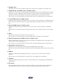
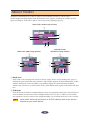
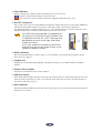
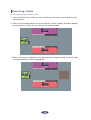
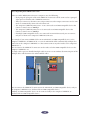
mLAN Graphic Patchbay
Owner’s Manual
Table of Contents
Introduction to
mLAN Graphic Patchbay ................ 2
Graphic View ...................................... 2
List View ............................................. 3
Using mLAN Graphic Patchbay
as a Plug-In ..................................... 4
Operational Flow.................................... 5
Starting mLAN Graphic Patchbay.......... 6
Menu Bar ................................................ 7
File Menu............................................ 7
View Menu.......................................... 8
Connection Menu ............................... 9
Help Menu......................................... 10
Tool Bar ................................................. 11
About Nodes ......................................... 13
Grayed-out Node ............................... 15
Relocating a Node ............................. 16
Swapping a Grayed-Out Node ........... 17
Viewing Node Information ................ 19
Connector Information Window ........ 24
mLAN Connection Settings................... 25
Wordclock Settings ............................ 25
Connecting Node Inputs
and Outputs ......................... 27
Disconnecting the Cable ................... 31
Saving and Opening an mLAN Graphic
Patchbay File or Template File ...... 33
Viewing the mLAN Connection
Settings in List View ...................... 34
Connecting Connectors in List View .. 36
Disconnecting Connectors ................. 37
Keyboard Shortcuts............................... 38
Error Messages ...................................... 39
Using S200-compatible
IEEE 1394 devices .......................... 40
Troubleshooting.................................... 41
Precautions
• The mLAN Graphic Patchbay software and this owner’s manual are the exclusive copyrights of
Yamaha Corporation.
• Duplication of the software or reproduction of this manual in whole or in part by any means is
expressly forbidden without the written consent of the manufacturer.
• Duplication of commercially-available music sequence data and/or digital audio files is strictly
prohibited, except for personal use.
• Yamaha makes no representations or warranties with regard to the use of the software or documentation and is not responsible for damages that result from the use of this manual or the
software.
• The mLAN Graphic Patchbay software may be updated without notice.
You can download the latest version of the software from the following URL:
http://www.yamahasynth.com/down/index.htm
• Screen displays in this owner’s manual are intended for instructional purposes only and may
appear different than screens displayed on your computer.
• Company and product names in this owner’s manual are the trademarks or registered trademarks of their respective companies.
This owner’s manual assumes that you are already familiar with basic Windows operations. If
you are not, please refer to the owner’s manual that came with your Windows software before
using mLAN Graphic Patchbay.
For information on hardware requirements, device interconnections and the installation of the
mLAN Graphic Patchbay software, refer to the separate “Installation Guide” as well as to the
owner’s manual for the respective mLAN device.
1
Introduction to mLAN Graphic Patchbay
mLAN Graphic Patchbay software enables you to set up and manage connections between mLAN
devices using a graphic user interface to connect and disconnect virtual audio/MIDI connectors and to
synchronize audio/MIDI signals between mLAN devices.
In this manual, setting up audio, MIDI, and wordclock routings is referred as to as making “mLAN
connections.”
You can immediately grasp the connections in their entirety by viewing displayed mLAN system
configuration graphics. You can also intuitively change audio and MIDI signal routing and wordclock
settings, much as if you were connecting physical cables.
Graphic View
Menu and Tool bars
These bars enable you to use various functions by selecting
menu options or clicking Tool bar buttons. (pages 7 and 11)
Node
Computers and mLAN
devices in an mLAN network
are called “nodes.” These
graphics provide information
about connected nodes
(page 13).
Input and output connectors
These connectors represent virtual audio/
MIDI/wordclock inputs and outputs for
each node. You can route audio/MIDI/
wordclock signals on an mLAN network by
using the graphic user interface to connect
these connectors (page 25).
2
Cable
This virtual cable indicates
connected nodes in an
mLAN network.
You can also view a list that shows the status of connections in an mLAN network. The list indicates the
status of audio and MIDI connections and enables you to modify these connections. For more
information, see page 34.
List View
Destination Connector List
Indicates connections between connectors
in the Audio Out and MIDI Out sections and
input connectors.
Audio Out and MIDI Out sections
Provide information on audio and
MIDI output connectors on all nodes
in an mLAN network.
Audio In and MIDI In sections
Provide information on audio and MIDI input
connectors on all nodes in an mLAN network.
3
Using mLAN Graphic Patchbay as a
Plug-In
You can start mLAN Graphic Patchbay as either stand-alone software or as a plug-in for an Open Plugin Technology compatible application.
Open Plug-in Technology (OPT) is a new software format that enables you to control MIDI devices
from a music software sequencer. For example, OPT enables you to start and operate various parts
of your music system, such as Plug-in Board editors and mixing control editors, directly from an
OPT-compatible sequencer. OPT also makes it unnecessary to set MIDI drivers for each application,
streamlining your music production system and making all operations more convenient and
seamless.
■ About OPT Levels
The client application and its compatibility with OPT can be divided into three levels, as shown
below.
Level 1 (OPT Panels) provides basic support for opening and displaying OPT control
panels that can transmit data via a clients’ external MIDI connectors.
Typically, this enables basic hardware editor control panels to operate properly.
Level 2 (OPT Processors) provides support for real-time MIDI processors and panel
automation. Typically, this enables both real-time and offline MIDI effects (e.g.,
arpeggiators, transposers, etc.) to operate properly and supply automation to OPT
panels.
Level 3 (OPT Views) provides support for edit views and MIDI processors and panels
that require direct access to client sequencer storage structures.
Typically, this enables support of sophisticated MIDI edit views (e.g., list editors, auto
accompaniment, data checkers, etc.).
■ OPT Level Implementation for mLAN Graphic Patchbay
This chart shows OPT-compatibility of mLAN Graphic Patchbay.
mLAN Graphic Patchbay operation
OPT levels of client application
Operation support
Operation limits
Views (Level 3)
Yes
None
Processors (Level 2)
Yes
None
Panels (Level 1)
Yes
None
All mLAN Graphic Patchbay functions work under the client applications of any OPT level (Panels
(Level 1), Processors (Level 2), and Views (Level 3)).
NOTE
Certain operations may not work as expected if there is no corresponding
function in the client application (sequencer, etc.). The highest level of
implementation for the client application is indicated in the OPT logo (which
appears along with the version information in the application).
4
Operational Flow
1. Connect the computer and mLAN devices using the IEEE1394 cables.
2. Start mLAN Graphic Patchbay (page 6).
3. Set up wordclock on the mLAN network (page 25).
4. Configure the routing of audio and MIDI signals on the mLAN network (page 25).
5. Specify the audio and MIDI inputs and outputs as per the owner’s manual for your
DAW (Digital Audio Workstation), audio sequencer, and/or connected devices.
For subsequent steps, refer to the owner’s manual for the software and connected devices.
■ Page reference
• To change the sampling frequency (Sample Rate)..........................................................See page 20.
• To set the number of audio channels for mLAN transmission
.........................................................................................See page 20 and 22.
• To change the nickname for the mLAN devices (nodes) or connectors .......................See page 22.
• To set the mLAN Driver Setup parameters .....................................................................See page 21.
• To change the latency ..................................... See the section regarding changing settings after
installation in the Installation Guide.
• If the computer and mLAN devices are unable to communicate .................................See page 41.
■ If multiple IEEE1394 interface cards have been installed on the computer:
mLAN Graphic Patchbay cannot simultaneously operate mLAN devices connected to multiple
IEEE1394 interface cards. Before you start mLAN Graphic Patchbay, select in the mLAN Driver Setup
window the IEEE1394 interface card you wish to use (page 21).
5
Starting mLAN Graphic Patchbay
After you successfully install mLAN Graphic Patchbay, follow the steps below to start the application.
1. When the mLAN Driver is inactive (
“ON.”
), right-click the Driver icon then select
2. Select [Graphic Patchbay] in the same menu.
NOTE
If the Driver icon does not appear in the Task bar, click the [Start] button, then
select [Programs | mLAN Tools | mLAN Manager]. The Task bar now indicates the
Driver icon.
Refer to the owner’s manual for the client application for details on starting the mLAN Graphic
Patchbay when using it as a plug-in(page 4).
6
Menu Bar
The Menu bar contains various editing and setup function commands. Click the desired menu name to
display the appropriate pull-down menu, then choose the command you wish to apply. Unavailable
commands are grayed-out.
File Menu
This menu enables you to store the current mLAN Graphic Patchbay settings in a file or template file
and retrieve the stored settings. For more information on files and template files, refer to page 33.
■ New
Creates a new default mLAN connection configuration and updates the graphic information. Select
this option to configure a new mLAN network.
■ Open
Opens an existing mLAN Graphic Patchbay (*.ymp) file and retrieves the stored mLAN connection
settings.
■ Save
Saves the current settings by overwriting the current mLAN Graphic Patchbay file (*.ymp).
■ Save As
Saves the current mLAN connection settings in a new file under a new name. You can also save an
existing file as a new file under a new name.
■ Open Template File
Opens an existing mLAN Graphic Patchbay template file (*.ymt).
■ Save Template File
Saves the current mLAN template file in a new template file under a new name. You can also save an
existing template file as a new file under a new name.
■ Exit
Closes mLAN Graphic Patchbay. This option is unavailable if you are using mLAN Graphic Patchbay
as a plug-in for the host application.
7
View Menu
■ Graphic
Displays the current mLAN connection settings graphically (page 2).
■ List
Displays the current mLAN connection settings in a list (page 3).
■ Update
Updates the information regarding mLAN devices (nodes) that are connected in the mLAN
network.
■ Destination Connector List
Displays the connection status of virtual audio and MIDI inputs and outputs.
■ Node Information (available only in Graphic view)
Provides information on a selected node (marked by a solid black frame) and enables you to change
various node settings (page 19).
■ Resource Information
Provides information on current IEEE1394 BUS bandwidth using a pie chart and a list. View this
information to ensure that there is sufficient bandwidth for additional audio connections.
NOTE
An error due to lack of bandwidth may occur even after you disconnect some
mLAN routings. Always update the resource information before checking the
available bandwidth.
8
Connection Menu
The Connection menu enables you to connect virtual audio, MIDI and wordclock inputs and outputs
for each node, route audio and MIDI signals; and synchronize mLAN devices in an mLAN network
(page 25).
■ Audio
Displays the Audio Connection window, which enables you to connect audio inputs and outputs
between nodes.
■ MIDI
Displays the MIDI Connection window, which enables you to connect MIDI inputs and outputs
between nodes.
■ Wordclock (available only in Graphic view)
Displays the Wordclock Settings window, which enables you to connect wordclock inputs and
outputs between nodes.
■ Single Master (available only in Graphic view)
Specifies the selected node (a node marked by a solid black frame) as the wordclock master, and the
other nodes as slaves. Wordclock connections between nodes will be made automatically (page 25).
Typically, you will use this function to specify the wordclock master in an mLAN network.
■ Input Connector/Output Connector (available only in Graphic view)
Displays the Input Connectors window or Output Connectors window for the selected node (a node
marked by a solid black frame).
This input (or output) connector is
connected to an output (or input)
connector of another node.
Click one of these connector
numbers for each node to open
the corresponding connector
information window.
If a node represents a computer,
each connector number
corresponds to an audio
channel or MIDI connector
number (that is, the number of
the mLAN driver).
This input (or output) connector is
currently selected.
These input (or output) connectors
are not connected.
■ Root
Specifies the currently selected node as the root. For details, refer to page 15.
9
Help Menu
■ Manual
Displays this PDF manual.
■ About
Displays mLAN Graphic Patchbay version information.
10
Tool Bar
Clicking icons on the Tool bar enables you to use the same functions and commands that you can access
from the Menu bar. Icons for unavailable functions are grayed-out.
1 23 45 6 7 8 9 J K L M N O PQ
R
A New
Creates a new default mLAN connection configuration and updates the graphic information. Select
this option to configure a new mLAN network.
You can also access this function by selecting [File], then [New] in the Menu bar.
B Open
Opens an existing mLAN Graphic Patchbay (*.ymp) file and retrieves the stored mLAN connection
settings (page 33).
You can also access this function by selecting [File], then [Open] in the Menu bar.
C Save
Saves the current settings by overwriting the current mLAN Graphic Patchbay file (*.ymp)
(page 33).
You can also access this function by selecting [File], then [Save As] in the Menu bar.
D Open Template File
Opens an existing mLAN Graphic Patchbay template file (*.ymt) (page 33). You can also access this
function by selecting [File], then [Open Template File] in the Menu bar.
E Save Template File
Saves the current mLAN template file in a new template file under a new name. You can also save an
existing template file as a new file under a new name (page 33). You can also access this function by
selecting [File], then [Save Template File] in the Menu bar.
F Audio
Displays the Audio Connection window, which enables you to connect audio inputs and outputs
between nodes (page 25).
You can also access this function by selecting [Connection], then [Audio] in the Menu bar.
G MIDI
Displays the MIDI Connection window, which enables you to connect MIDI inputs and outputs
between nodes (page 25).
You can also access this function by selecting [Connection], then [MIDI] in the Menu bar.
H Wordclock (available only in Graphic view)
Displays the Wordclock Settings window, which enables you to connect wordclock inputs and
outputs between nodes (page 25).
You can also access this function by selecting [Connection], then [Wordclock] in the Menu bar.
11
I Change View
Switch the view of the current mLAN connection settings between Graphic view and List view.
J Single Master (available only in Graphic view)
Specifies the selected node (a node marked by a solid black frame) as the wordclock master, and the
other nodes as slaves. Wordclock connections between nodes will be made automatically (page 25).
Typically, you will use this function to specify the wordclock master in an mLAN network.
You can also access this function by selecting [Connection], then [Single Master] in the Menu bar.
K In (available only in Graphic view)
Displays the Input Connectors window of the selected node (a node marked by a solid black frame).
You can also access this function by selecting [Connection], then [Input Connector] in the Menu
bar.
L Out (available only in Graphic view)
Displays the Output Connectors window of the selected node (a node marked by a solid black
frame).
You can also access this function by selecting [Connection], then [Output Connector] in the Menu
bar.
M Root
Specifies the currently selected node as the root (page 15).
You can also access this function by selecting [Connection], then [Root] in the Menu bar.
N Node Information (available only in Graphic view)
Provides information regarding a selected node (marked by a solid black frame) and enables you to
change various node settings (page 19).
You can also access this function by selecting [View], then [Node Information] in the Menu bar.
O Destination Connector List
Displays the connection status of virtual audio and MIDI inputs and outputs.
You can also access this function by selecting [View], then [Destination Connector List] in the Menu
bar.
P Update
Updates the information regarding mLAN devices (nodes) that are connected in the mLAN
network.
You can also access this function by selecting [View], then [Update] in the Menu bar.
Q Manual
Displays this PDF manual. You can also access this function by selecting [Help], then [Manual] in
the Menu bar.
R File name
This area indicates the name of the currently-opened file (*.ymp). Click the name to display the
Open dialog box, which you can also access by selecting [File | Open] from the Menu bar.
12
About Nodes
Computers and mLAN devices that are connected in an mLAN network are called “nodes.”
mLAN Graphic Patchbay displays node information in the graphics, including the number of node
inputs and outputs, node names, and the current operating sampling frequency.
Audio node (Audio Setup window)
4
2
3
1
5
6 7
MIDI node (MIDI Setup window)
Wordclock node
(Wordclock Setup window)
4
4
2
3
1
2
3
1
5
5
89
6 7
A Node icon
Click a node icon to display and, if desired, change settings for the corresponding node (page 19).
Clicking the icon in the audio and wordclock setup windows displays the Node Information (Audio)
window. Clicking the icon in the MIDI setup window displays the Node Information (MIDI)
window. You can also access this function via the [Node Information] option in the Menu and Tool
bars.
B ID button
Click this button to flash the ACTIVE indicator on the corresponding mLAN device. This function is
useful in mLAN networks that include multiple mLAN devices because it enables you to identify
correspondences between nodes in the Graphic Patchbay screen and mLAN devices in the network.
NOTE
Some mLAN devices do not feature an ACTIVE indicator. Refer to the owner’s
manuals for your mLAN devices.
13
C Error indicator
Indicates whether the signal is being transmitted or received correctly.
: Signal is being transmitted or received correctly.
: An error has occurred. Click the indicator to display details about the error.
D IN/OUT connectors
These connectors represent audio, MIDI and wordclock inputs and outputs in the Audio, MIDI and
Wordclock Connection windows. To change connections, click a connector to display the
corresponding Input or Output window (page 9). The window indicates the node connectors and
magnified connectors to which virtual cable connectors are connected.
NOTE
If the IEEE 1394 bus bandwidth is overloaded, or if
you connect an mLAN device that had been used
in a different network, the “OUT” connector may
be displayed as shown at the right, and will be
unable to transmit.
In this case, reduce the number of transmission
channels that you’re using (page 39–40), or use
[Update] to update the data.
➪
E Node nickname
You can assign nicknames to nodes (page 19). If a nickname is not assigned, the product model
name (page 19) appears.
F Sample rate
Displays the current operating sampling (wordclock) frequency (44.1 kHz, 48 kHz, 88.2 kHz, or
96 kHz).
G Master/Slave number
Displays the wordclock master or slave number.
H M(aster) button
The button indicator lights up when the node is operating as master. The button indicator turns off
when the node is operating as a slave. To switch the node from slave to master, click this button to
turn on the indicator (page 27).
I Root indicator
The button indicator lights up when the node is operating as root. If you click the button, that node
will operate as the root.
14
About the Root function
In a network of mLAN devices, the “root” is the node that is the reference point for data
transmission. This means that even in the same network environment, there may be slight differences
in audio quality depending on the root. In a professional recording environment or similar critical
situation, we recommend that you always specify the same node as the root in order to ensure
uniform audio quality.
Since the root setting is saved in the Graphic Patchbay file, the root setting will be recovered when
you recall the file. However, the root node may change if you power-off an mLAN device or
disconnect an IEEE 1394 cable while you’re working.
In this case, you can press the root indicator button of the note you want to restore as the root, or
recall the Graphic Patchbay setting file.
NOTE
You can’t specify the computer as the root.
Grayed-out Node
If mLAN Graphic Patchbay fails to detect a node that had been recognized before you updated the
information, the node will be grayed-out and unavailable for settings adjustments. In this case, rightclick the grayed-out node to display the [Delete] pop-up menu. Click the [Delete] button to delete the
node.
15
Relocating a Node
You can drag-and-drop to relocate a node.
1. Move the pointer to a node you wish to relocate, then press and hold down the
mouse button.
2. While you are holding down the mouse button, mLAN Graphic Patchbay displays
brown boxes to which you can relocate the selected node.
3. While continuing to hold down the mouse button, drag the node to a brown box.
The destination box will be highlighted.
16
4. Release the mouse button. The node is relocated.
Swapping a Grayed-Out Node
If mLAN Graphic Patchbay displays both a grayed-out node (page 15) and a new node of the same
model that has not yet been connected to any node, you can swap nodes. After you swap nodes, the
connection settings for the grayed-out node will be applied to the new node. The grayed-out node will
be deleted. This saves you from patching nodes from scratch when you change an mLAN device or use a
different mLAN device of the same model in a new location.
NOTE
• You can swap a grayed-out node and a new node only if both nodes are for
the same model.
• To swap the nodes, no input or output connectors of the new node should be
connected.
1. Move the pointer to the new node, then press and hold down the mouse button.
17
2. While you are holding down the mouse button, a swappable grayed-out node is
indicated with a yellow frame.
3. While holding down the mouse button, drag the new node to the swappable
grayed-out node, then release the mouse button.
4. The grayed-out node will be replaced by the new node.
18
Viewing Node Information
In Graphic view, you can display and change detailed node information by clicking the node icons
(page 13) for the computer and mLAN devices, or selecting a node and then selecting [Node
Information] from the [View] menu. The Node Information (Audio) window opens from the Audio or
Wordclock Connection windows, and the Node Information (MIDI) window opens from the MIDI
Connection window.
Node Information (Audio) window
■ Vendor
Indicates the manufacturer of the node device.
■ Model Name
Indicates the model of the node device.
■ Model Nickname
Indicates and enables you to change the node nickname. You can assign any nickname (up to 32
characters) to help identify the node. You cannot use two-byte characters (such as Japanese or
Chinese characters).
■ GUID
Indicates a unique ID for mLAN device nodes. If two nodes are mLAN devices of the same model,
the IDs are different for each device.
If the node represents a computer, this field indicates the ID for the IEEE1394 card.
19
■ Version
If the node represents a computer, the field indicates the mLAN driver version.
If the node represents an mLAN device, the field indicates the device firmware version.
■ Supported Sample Rate (kHz)
Indicates sampling (wordclock) frequencies supported by the node. Sampling frequencies that are
not supported by the node are grayed-out.
■ Maximum Number of Connected Nodes
Displays the maximum number of audio nodes that can be connected to the nodes’ audio input
connectors.
For more information, refer to page 23.
■ Connector Name
Enables you to select an audio input or output connector. The ID and nickname of the selected
connector will be displayed in the [Connector ID] and [Connector Nickname] fields.
NOTE
If the node is a computer, the audio or MIDI [Connector ID] will match the
number of an audio channel or MIDI connector specified on the DAW (that is,
the number of the mLAN driver).
■ Sample Rate
If the selected node is operating as wordclock master, you can change the sampling frequency here. If
the selected node is operating as wordclock slave, this field indicates (but does not allow you to
change) the current sampling frequency.
NOTE
On some mLAN devices, it is necessary to set up the wordclock/sampling
frequency. For more information, refer to the owner’s manual for your mLAN
device.
NOTE
Some mLAN devices support certain sampling frequencies only when the
devices synchronize with incoming signals. For more information, refer to the
owner’s manual for your mLAN device.
NOTE
If the error message “Cannot change” is displayed, refer to “If you cannot
change the sampling frequency or the number of output channel” on page 23
and “Unable to change the mLAN settings” on page 42 in the Troubleshooting
section.
■ Number of Channels
Displays the maximum number of audio input channels, and displays and enables you to set the
maximum number of audio output channels.
NOTE
If a node represents a computer, the number of audio input connectors is fixed
to 32 CH.
NOTE
Some devices (such as the n8/n12) do not allow you to change the number of
output channels.
NOTE
If the error message “Cannot change” is displayed, If the error message “Cannot
change” is displayed, refer to “If you cannot change the sampling frequency or
the number of output channels” on page 23 and “Unable to change the mLAN
settings” on page 42 in the Troubleshooting section.
20
■ Icon
Enables you to change the node icon (page 13).
■ Bkgrnd Color
Enables you to change the background color of the nodes.
■ OK
Confirms the settings and closes the window.
■ Cancel
Cancels the settings and closes the window.
■ Setup
If the node represents a computer, clicking the [Setup] button displays the mLAN Driver Setup
window (refer to “Changing settings after installation” in the Installation Guide).
If the node represents an mLAN device, clicking the [Setup] button displays the mLAN Control
Panel window (refer to “Setting up from the mLAN Auto Connector” in the installation Guide).
Node Information (MIDI) window
21
■ Vendor
Indicates the manufacturer of the node device.
■ Model Name
Indicates the model of the node device.
■ Model Nickname
Indicates and enables you to change the node nickname. You cannot use two-byte characters (such as
Japanese or Chinese characters).
■ GUID
Indicates a unique ID for mLAN device nodes. If two nodes are mLAN devices of the same model,
the IDs are different for each device.
If the node represents a computer, this field indicates the ID for the IEEE1394 card.
■ Version
If the node represents a computer, the field indicates the mLAN driver version.
If the node represents an mLAN device, the field indicates the device firmware version.
■ Maximum Number of Connected Nodes
Display the maximm number of MIDI nodes that can be connected to the node MIDI input
connectors. For more information, refer to page 23.
If the node represents a computer, this field indicates the maximum number of nodes that can be
connected to an S400-compatible device and an S200-compatible device separately.
The following example indicates that up to two S400-compatible devices and one S200compatible device can be connected to the computer’s MIDI inputs.
■ Connector Name
Enables you to select a MIDI input/output connector. The ID and nickname of the selected
connector will be displayed in the [Connector ID] and [Connector Nickname] field.
NOTE
If the node is a computer, the audio or MIDI [Connector ID] will match the
number of an audio channel or MIDI connector specified on the DAW (that is,
the number of the mLAN driver).
■ Number of Connectors
Displays the maximum number of MIDI input and output connectors available to the node.
■ Icon
Enables you to change the node icon (page 13).
■ Bkgrnd Color
Enables you to change the background color of the nodes.
■ OK
Confirms the settings and closes the window.
22
■ Cancel
Cancels the settings and closes the window.
■ Setup
If the node represents a computer, clicking the [Setup] button displays the mLAN Driver Setup
window (refer to “Changing settings after installation” in the installation Guide).
If the node represents an mLAN device, clicking the [Setup] button displays the mLAN Control
Panel window (refer to “Setting up from the mLAN Auto Connector” in the Installation Guide).
If you cannot change the sampling frequency or the number of output
channels:
To change the computer’s sampling frequency or the number of output channels, you must first shut
down the DAW or audio sequencer that is using the mLAN driver.
1. Shut down the DAW or audio sequencer.
2. If you were using mLAN Graphic Patchbay as a plug-in for the host application,
restart mLAN Graphic Patchbay as a stand-alone application (page 6).
3. In the Node Information window, edit the sampling frequency and/or the
number of output channels as necessary (page 19).
4. Restart the DAW or audio sequencer.
About the Maximum Number of Connected Nodes
The Maximum Number of Connected Nodes field in the Node Information (Audio) window
indicates the maximum number of audio nodes that can be connected to the audio input of the
corresponding node.
The Maximum Number of Connected Nodes field in the Node Information (MIDI) window
indicates the maximum number of MIDI nodes that can be connected to the MIDI input of the
corresponding node.
For example, assume that the maximum numbers of connected nodes are as follows:
• The maximum number of connected nodes indicated in the Node Information (Audio)
window: four units
• The maximum number of connected nodes indicated in the Node information (MIDI)
window: two S400s and one S200
In this case, you can connect up to four S400s and S200s combined as Audio nodes to the computer
node.
You can connect up to two S400s and one S200 as MIDI nodes.
NOTE
On a computer, you can connect only one S200 to a computer node.
23
Connector Information Window
In Graphic view, clicking the connector number in the Input or Output window (page 9) displays the
Input or Output Information window, in which you can view and change detailed information,
including the connector nickname and connecting destination. The connector Information (Audio)
window opens from the Audio window. The connector Information (MIDI) window opens from the
MIDI Connection window.
■ Vendor
Indicates the manufacturer of the node device.
■ Model Nickname
Indicates the nickname of the node device.
■ Connector Nickname
Indicates and enables you to change the connector nickname. You cannot use two-byte characters
(such as Japanese or Chinese characters).
If no nickname is assigned, this field indicates the connector name.
■ Source Name (Displayed only in the Input Information window)
Displays the nickname of the destination node and output connector.
■ OK
Confirms the settings and closes the window.
■ Cancel
Cancels the settings and closes the window.
24
mLAN Connection Settings
This section describes how to connect or disconnect audio or MIDI connectors between nodes, and
change wordclock and other mLAN connection settings.
You can easily change the audio, MIDI or wordclock signal routing in an mLAN network by intuitively
re-patching the cables in the graphic user interface.
Wordclock Settings
There are two ways to set the wordclock:
• Follow the steps described in “Connecting the Node Input and Outputs” (page 27) to connect
the wordclock connectors one by one.
• Use the [Single Master] option.
This section explains how to use the [Single Master] option.
You can easily set up the wordclock by using the [Single Master] option. You do not need to connect the
wordclock connectors one by one. Typically, you will use this option to specify the wordclock master in
an mLAN network.
NOTE
• If you wish to specify two wordclock masters in an mLAN network and
connect the wordclock connectors manually, follow the steps described in the
“Connecting the Node Input and Outputs” section (page 27).
• Most functions selected from the Menu bar can also be accessed from the Tool
bar.
1. In the [Connection] menu, select [Wordclock].
The Wordclock Setup window opens.
2. Move the mouse to select the node you wish to assign as wordclock master.
The selected node is highlighted by a solid black frame.
3. In the [Connection] menu, select [Single Master].
25
4. The wordclock connector for each node is connected automatically.
The selected node is assigned as wordclock master, and other nodes as slave.
5. Click the node icon (page 13) for the wordclock master node. (Alternatively, in the
[View] menu, select [Node Information].)
The Node Information (Audio) window opens.
6. Select the sampling frequency in the [Sample Rate] field in the Node Information
(Audio) window.
The sampling frequency specified here will be automatically used by the slave nodes.
NOTE
If the error message “Cannot change” is displayed, If the error message “Cannot
change” is displayed, refer to “If you cannot change the sampling frequency or
the number of output channels” on page 23 and “Unable to change the mLAN
settings” on page 42 in the Troubleshooting section.
26
Connecting Node Inputs and Outputs
You can control the audio, MIDI or wordclock signal routings in an mLAN network by connecting the
node inputs and outputs.
You can connect the node inputs and outputs by either (a) patching the cables one by one, or (b)
simultaneously patching multiple cables as a group.
NOTE
• You should also refer to “Notes Regarding Node MIDI Connection” on
page 32.
• You cannot connect the MIDI or wordclock connectors as a group.
• For wordclock connections, using the [Single Master] option is easier
(page 25).
■ Patching the cables one by one
NOTE
The following procedure applies to the Audio Connection window. However,
you can also follow this procedure to connect the MIDI and wordclock
connectors.
1. Click the [OUT] connector of the node that outputs the signal.
mLAN Graphic Patchbay displays the Output Connector window, which shows enlarged node
connectors and virtual cable connectors.
NOTE
• To connect the wordclock input and output connectors, first turn on the
button (page 13) of the master node before clicking the [OUT] connector.
Otherwise, the Output Connector window will not open.
• If you connect the wordclock input and output connectors, the node with the
output connector is set as master, and the nodes with input connectors are set
as slaves. Slave nodes will use the sampling frequency setting of the master
node.
27
2. In the Output Connectors window, click the box next to the output connector
number to be connected.
A virtual cable connector appears in the box.
3. Click the [IN] connector of the node that receives the input signal.
mLAN Graphic Patchbay displays the Input Connectors window.
28
4. In the Input Connectors window, click the box next to the input connector to be
connected.
The input and output connectors are now connected by a cable of the same color as the output node.
■ Connecting multiple cables simultaneously as a group
NOTE
You must select consecutive connector numbers for group connection.
1. Click the [OUT] connector of the node that outputs the signal.
mLAN Graphic Patchbay displays the Output Connectors window.
2. In the Output Connectors window, click the box next to the number of the first
output connector to be connected.
3. While pressing and holding down the <Shift> key on the computer keyboard, click
the box next to the number of the last output connector to be connected.
A virtual cable connector appears in each of the output connector boxes in the range specified in
Steps 2 and 3.
29
4. Click the [IN] connector of the node that receives the input signal.
mLAN Graphic Patchbay displays the Input Connectors window.
5. Click the box next to the number of the first input connector targeted for group
connection.
6. A virtual cable connector appears in each of the input connector boxes, starting
with the input connector selected in this step. The specified multiple input and
output connectors are connected by a virtual cable of the same color as the output
node.
NOTE
• For group connection, be sure to specify the output connectors first.
• Only a single cable appears in a group connection, or when you connect
consecutive input and output connectors.
30
Disconnecting the Cable
To disconnect the cable, you can either (a) delete it from the pop-up menu, or (b) use the <Delete> key
on the computer keyboard.
■ Deleting the cable from the pop-up menu
1. Right-click the cable you wish to disconnect.
The selected cable is now represented by a dotted line, and a pop-up menu appears. The numbers in
the pop-up menu indicate the connector numbers to which virtual cables are connected.
2. In the pop-up menu, click the number of the connector you wish to disconnect.
The cable connecting to the connector will be disconnected. Selecting [All] will disconnect all
connectors indicated in the pop-up menu.
■ Using the <Delete> key on the computer keyboard
1. Click the cable you wish to disconnect.
The selected cable is now represented by a dotted line.
2. Press the <Delete> key on the computer keyboard.
mLAN Graphic Patchbay displays a confirmation message.
3. Click [Yes].
4. The selected cable is disconnected.
NOTE
If multiple connector connection is represented by a single cable (such as group
connection), this procedure will disconnect all connector connections.
31
Notes Regarding Node MIDI Connection
When you make MIDI connections on a computer, note the following:
• Each group of eight ports of the node MIDI OUT connector will be connected to a group of
eights ports on another node’s MIDI IN connector.
• When you connect or disconnect one output connector, other output connectors on the same
node are automatically connected or disconnected.
• The computer’s MIDI IN connectors 1-16 are connected to an S400-compatible device that
features a transfer rate of 400Mbps.
• The computer’s MIDI IN connector 17 is connected to an S200-compatible device that
features a transfer rate of 200Mbps.
• If multiple S200-compatible devices are connected in an mLAN network, you can connect
only one of them to the computer’s MIDI IN connector.
For example, if you connect MIDI OUT 1 on an mLAN16E (an S400-compatible device) to the
computer’s MIDI IN 5, all MIDI OUTs (1-4) on the mLAN16E will be automatically configured as
connectors to the computer’s MIDI INs 1-4. You cannot connect any other nodes to the computer’s
MIDI INs 5-8.
You can connect the MIDI OUT connectors on the nodes of other S400-compatible devices to the
computer’s MIDI IN 9-16.
If a single cable represents bundled multiple cables in an on-screen window, disconnecting one of the
multiple cables will disconnect the other bundled cables.
You can connect the MIDI OUT connector on the mLAN16E (an S400-compatible device) only to
the computer’s MIDI IN 1-16 (dedicated for an S400-compatible device).
Similarly, an S200-compatible device can be connected only to the computer’s MIDI IN 17
(dedicated for an S200-compatible device).
32
Saving and Opening an mLAN Graphic
Patchbay File or Template File
You can store mLAN connection settings in a file (extension: *ymp) or in a template file (extension:
*ymt), and retrieve them later. The difference between a file and template file is as follow:
■ File (*ymp)
An mLAN Graphic Patchbay file enables you to store and retrieve all mLAN Graphic Patchbay settings.
If your mLAN devices are fixed, as for example in a home recording environment, store the settings in a
file. Since the file stores an ID number for each device, you cannot use the stored mLAN connection
settings if you replace a unit, even with another unit of the same model.
■ Template File (*ymt)
An mLAN Graphic Patchbay template file enables you to store and retrieve all mLAN Graphic Patchbay
settings other than model nicknames and connector nicknames. If you replace a unit, as long as the new
unit is the same model as the previous unit, you will be able to use the stored mLAN connection
settings.
A template file is useful when you wish to recreate your home-recording mLAN connections on devices
in another studio. If you save your basic mLAN connections in a template file, you will not need to set
up the connections from scratch when you visit another studio. This will enable you to configure a
network quickly and efficiently.
33
Viewing the mLAN Connection
Settings in List View
You can view the mLAN connection settings in an mLAN network in a list. List view displays the status
of, and enables you to change, audio and MIDI connections.
To switch between Graphic view and List view, in the [View] menu select [Graphic] or [List].
Alternatively, click the [Change View] button in the Tool bar.
To switch between the Audio Connection window and MIDI Connection window, in the [Connection]
menu select [Audio] or [MIDI]. Alternatively, click the [Audio] or [MIDI] button in the Tool bar.
NOTE
In List view, you cannot set up wordclock. Some menus are also unavailable.
Unavailable menus and Tool bar buttons are grayed-out.
Audio Connection window (List)
3
1
2
MIDI Connection window (List)
3
1
2
34
A Audio Out and MIDI Out sections
Display information regarding the audio or MIDI output connectors for all nodes in an mLAN
network.
B Audio In and MIDI In sections
Display information regarding the audio or MIDI input connectors for all nodes in an mLAN
network.
C Destination Connector List section
Identifies connections between connectors in the Audio Out or MIDI Out sections and input
connectors.
■ Model name
Indicates the model nickname of the node.
■ Connector name
Indicates the connector nickname.
■ Vendor
Indicates the manufacturer of the node.
■ Format
Indicates the sampling frequency and transmission format of a node.
■ WCLK
Indicates the node’s wordclock master or slave number. An “M” represents that the node is operating
as the master. An “S” represents that the node is operating as a slave. This parameter appears only in
the Audio Connection window.
35
Connecting Connectors in List View
This section describes how to connect the audio and MIDI connectors in List view.
1. In the Audio Out or MIDI Out sections, click the output connector you wish to
connect.
To connect multiple connectors simultaneously (group connection), click the first output connector
in the output group to be connected, then while holding down the <Shift> key on the computer
keyboard, click the last output connector in the group.
The selected connectors will be highlighted in the list.
2. In the Audio In or MIDI In section, click the input connector to which you wish to
connect.
To connect multiple connectors simultaneously (group connection), click the first input connector
in the input group to be connected.
The selected input connectors will be highlighted in the list.
36
3. Click the [Connect] button. The selected input and output connectors connect to
each other. The Destination Connector List section displays each input connector
that is now connected to a corresponding output connector listed in the Audio Out
or MIDI Out column.
NOTE
If the input connectors and output connectors are connected incorrectly, the
[Connect] button will be grayed-out.
Disconnecting Connectors
This section explains how to disconnect audio and MIDI connectors.
1. Select the connector you wish to disconnect in the Audio Out or MIDI Out sections
or in the Destination Connector List section.
To disconnect multiple connectors simultaneously (group disconnection), click the first output
connector in the group to be disconnected, then hold down the <Shift> key on the computer
keyboard and click the last connector in the group.
The selected connectors are highlighted in the list.
2. Click the [Disconnect] button.
The selected connectors are disconnected.
37
Keyboard Shortcuts
Menu
File
Menu Option
Keyboard Shortcuts
New
1) Alt+F → N
2) Ctrl+N
Open
1) Alt+F → O
2) Ctrl+O
Save
1) Alt+F → S
2) Ctrl+S
Save As
1) Alt+F → A
Open Template File
1) Alt+F → T
2) Ctrl+L
Save Template File
1) Alt+F → Z
2) Ctrl+U
Exit
1) Alt+F → X
Graphic
1) Alt+V → G
2) Ctrl+1
List
1) Alt+V → L
2) Ctrl+2
Update
1) Alt+V → U
2) Ctrl+3
Destination Connector List
1) Alt+V → C
2) Ctrl+4
Node Information
1) Alt+V → N
2) Ctrl+5
Resource Information
1) Alt+V → R
2) Ctrl+6
Audio
1) Alt+C → A
2) Ctrl+7
MIDI
1) Alt+C → M
2) Ctrl+8
Wordclock
1) Alt+C → W
2) Ctrl+9
Single Master
1) Alt+C → S
2) Ctrl+0
Input Connector
1) Alt+C → I
2) Ctrl+I
Output Connector
1) Alt+C → O
2) Ctrl+B
Root
1) Alt+C → R
2) Ctrl+Y
Manual
1) Alt+H → M
2) F1
About
1) Alt+H → A
View
Connection
Help
NOTE
In Graphic view, you can also select the node by pressing the [Tab] key.
38
Error Messages
Failed to set Sample Rate.
When the node represents a computer:
Shut down your DAW, make the necessary settings
in Graphic Patchbay, then start the DAW (page 23).
Some parameters cannot be changed while the DAW
or editor application using the mLAN driver is
running.
Failed to set the node as the wordclock
master.
When the node represents an mLAN device:
Make sure all cables are securely and correctly
connected to mLAN devices, and the power to the
mLAN devices is turned on.
Failed to change the number of audio
output channels for the next node. (Node
nickname, or device model name if a
nickname has not been specified.)
Failed to set the number of MIDI output
ports.
Make sure that the wordclock and sampling
frequency settings on the corresponding mLAN
device are correct.
Failed to connect audio.
Failed to connect wordclock.
The sampling rate (Sample Rate) setting
differs from that specified on the device.
Set the sampling rate correctly.
Set the sampling rate of the audio node in the Node
Information (Audio) window (page 20).
Found an mLAN device not compatible
with S400.
The number of available channels will
decrease.
You may need to reduce the number of
transmission channels to be able to make
mLAN connections.
For more information, refer to “Error
Messages” or “Troubleshooting” in the
mLAN Graphic Patchbay Online Manual.
If you connect even a single mLAN device that does
not support S400, all other mLAN devices in the
network will match the functions and limitations of
the non-S400-compatible device. For example, if
you connect an S400-compatible device and an
S200-compatible device in a network, the S400compatible device will conform to the performance
of the S200-compatible device. Therefore, the
number of transmission channels on each device will
be limited. (See the table below.)
Number of transmission channels available in a network that includes a
single S200-compatible device and multiple S400-compatible devices:
Number of mLAN devices
(including the computer)
Total number of available transmission channels*1
(with a sampling frequency of 44.1 kHz or 48 kHz)
2
40
3
44
4
37
5
32*2
*1. Applicable if the number of transmission channels on the computer is 32, except if the number
of mLAN devices is five.
*2. The number of available transmission channels on the computer is limited to 24.
39
The number of devices that can be
connected to the computer has been
exceeded.
In the Node Information (Audio) window, check the
maximum number of audio nodes that can be
connected (page 20).
In the Node Information (MIDI) window, check the
maximum number of MIDI nodes that can be
connected (page 22).
Data reception error. The computer
resources or processing power may be
insufficient.
Try the following measures:
1) Quit all other applications.
2) Increase the Latency value (see the Installation
Guide).
3) If multiple mLAN devices exist in the network, set
“Required CPU” in the mLAN Driver Setup
window to “Mid” or “Low Performance.”:
4) Click the [Update] button.
5) Restart the computer.
Using S200-compatible IEEE 1394 devices
When using IEEE 1394 devices of the slower S200 type, the number of available audio transmission
channels in the network is reduced. Before connecting an S200-compatible device to the network, make
sure to change the number of transmission channels with the following procedure.
1. Change the number of output (transmission) channels of each S400-compatible
device from the Node Information (Audio) window so that it does not exceed the
total number of output (transmission) channels of all S200 and S400 devices in the
network. (Refer to the table at the bottom of the Error Messages section.)
NOTE
When connecting an S200-compatible device in step 2, the number of output
channels of the S200 device is set to maximum automatically. Confirm the
maximum number of output channels of the S200 device you are using, then
change the number of output channels on the S400 devices accordingly. For
information on the maximum number of output channels, refer to the owner’s
manual of your particular S200 device.
2. Connect the S200-compatible device to the computer or the mLAN device in the
network.
3. To increase the number of output (transmission) channels of S400-compatible
devices, decrease the number of output channels of the S200 devices from the
Node Information (Audio) window, and change the number of output channels of
the S400 devices.
40
Troubleshooting
■ Unable to communicate via mLAN
• The mLAN Driver/mLAN Tools may not have been installed or set up correctly.
....................................................................Refer to the Installation Guide.
• Make sure that the driver is enabled. (The driver icon should be blue.) Right-click the
driver icon on the task bar and click “ON”.
................... Refer to “Checking after Installation” in the Installation Guide.
• Has mLAN connection been enabled? Try setting up again. ................ Refer to page 25.
• There may be a limit on the IEEE 1394 interface of your computer as to the number of
ports that can be used simultaneously. Check how many ports can be used simultaneously...........Refer to “Maximum Number of Connected Nodes” on pages 20 and 22.
• Make sure that you set up the wordclock correctly. Also, make sure that one node is
assigned as master and the other nodes are assigned as slaves. ........... Refer to page 25.
• Make sure that the IEEE 1394 (mLAN) cable is connected properly, and that the power
to the mLAN device has been turned on. Disconnect the mLAN cable once, then insert it
again.
• Is there a loop connection? Check the cabling and make sure none of the devices are
connected in a loop.
Example of a loop connection
Computer
Computer
mLAN device
mLAN device
: IEEE 1394-equipped device
• Turn off all devices on the mLAN network (except the computer) and re-connect each
device one-by-one until the device causing the problem is found.
• There may be multiple IEEE 1394 interfaces installed on the computer. In this case, rightclick the driver icon on the task tray, then select Driver Setup, and then select one of the
IEEE 1394 interfaces to which you wish to connect the mLAN device. Finally, re-insert
the IEEE (mLAN) 1394 cable, then establish mLAN connection again.
....................... Refer to “Driver Setup” on page 6 in the Installation Guide.
• (When using 01X/i88X/mLAN16E/MY16-mLAN: ) Is the ACTIVE lamp lit (in blue)? If it is
not lit, restart the mLAN device then establish mLAN connection again.
....................... Refer to “Driver Setup” on page 6 in the Installation Guide.
• Have you changed the device? Even if the model is the same, if the actual device is different, you will need to re-enable connection...................................... Refer to page 25.
■ The computer processing speed is too slow.
• If multiple S200-compatible devices are connected to the network, connecting mLAN
devices in mLAN Graphic Patchbay may require more time.
41
■ Unable to change the mLAN settings
• When using the mLAN driver with a program such as a DAW, the mLAN settings cannot
be changed. Quit all applications using the mLAN Driver, then change the mLAN settings.................................................................................................... Refer to page 23.
• Is the mLAN WDM driver selected as the default audio device for Windows? (Windows
may select the mLAN WDM driver as the default audio device automatically when you
turn the power on to the mLAN device.) You may not be able to change the mLAN settings even if the application is not active. If the mLAN WDM driver is selected as the
default device (“mLAN Audio Out” or “mLAN MIDI Out”), remove the mLAN WDM
driver once by following the instructions below, restart the computer, then change the
mLAN settings.
Windows XP
1. From the Start menu, select ([Settings] ➝) [Control Panel] ➝ [Sounds and Audio
Devices] ➝ [Voice]. Make sure that something other than “mLAN Audio Out” is
selected for the “Voice playback” setting.
2. From the Start menu, select ([Settings] ➝) [Control Panel] ➝ [Sounds and Audio
Devices] ➝ [Audio]. Make sure that something other than “mLAN Audio Out” is
selected for the “Sound playback” setting.
3. From the Start menu, select ([Settings] ➝) [Control Panel] ➝ [Sounds and Audio
Devices] ➝ [Audio], then select any option other than the items from “mLAN MIDI
Out” through “mLAN MIDI Out (16)” for the “MIDI music playback” setting.
Windows Vista
From the Start menu, select ([Settings] ➝) [Control Panel] ➝ [Sound] ➝ [Playback].
Make sure that something other than “Line Out mLAN Audio Out” is selected, then
click [Set Default].
• Set the sound setting of Windows to “No sounds” by following the instructions below
after restarting the computer.
Windows XP
Select [Start] (➝ [Settings]) ➝ [Control Panel] ➝ [Sounds and Audio Devices] ➝
[Sounds], then select “No Sounds” in the [Sound scheme].
Windows Vista
Select [Start] (➝ [Settings]) ➝ [Control Panel] ➝ [Sound] ➝ [Sounds], then select “No
Sounds” in the [Sound Scheme].
■ mLAN Manager (the Driver icon in the Task bar) has disappeared.
• Select [Start] ➝ [(All) Programs] ➝ [Start Up] or [mLAN Tools], then select mLAN Manager.
■ A connected mLAN device is not recognized.
• Refresh the information by selecting [View], then [Update] in the Menu bar.
.......................................................................................... Refer to page 8.
■ Connections are changed each time you start mLAN Graphic Patchbay.
• If the network includes a non-S400-compatible device, the total number of transmission
channels of all devices will be reduced. mLAN Graphic Patchbay recalls the previous
connections of the mLAN devices in the order of power-up. Channels in excess of the
permitted number will not be connected.
• If five or more mLAN devices (including a computer) have been connected to a network,
the total number of transmission channels for all devices will be limited. For example, if
the sampling frequency is set to 44.1 kHz or 48 kHz, the number of available channels
on a Windows computer would be 86 channels.
42
■ It takes a while to start mLAN Graphic Patchbay or to update the information
using the Update menu option.
• If you try to update the network information after you connect or disconnect an mLAN
device that does not support S400, the computer changes the mLAN transmission
speed. This extra process may slow down the operation. However, the process will not
affect subsequent performance.
■ An error message appears when opening a template file.
• Depending on the specifications of the computer and IEEE1394 card, there are two situations: 1) up to four mLAN devices can be connected, and 2) up to two mLAN devices
can be connected. If you’ve established the mLAN connection and saved the settings as
a template file on the computer/IEEE1394 card which enables you to connect up to four
mLAN devices, and then you open the template file on the computer/IEEE1394 card
which enables you to connect up to just two mLAN devices, an error message is called
up. If such a situation occurs, use only up to two mLAN devices. You can confirm the
amount (two or four) of the mLAN devices which can be connected on the Information
window of the Driver Setup. Half of the tab’s amount indicates the maximum number of
the mLAN devices which can be connected.
U.R.G., Pro Audio & Digital Musical Instrument Division, Yamaha Corporation
© 2004 Yamaha Corporation