1
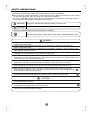
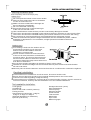
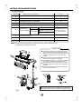
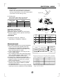
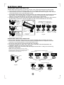
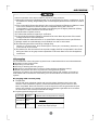
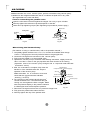
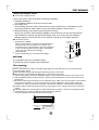
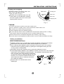
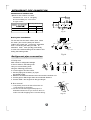
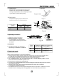
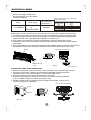
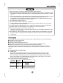
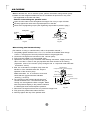
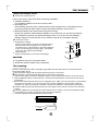
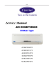
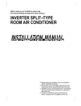
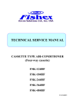
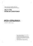
Before using your air conditioner, please read
this manual carefully and keep it for future reference.
SPLIT-TYPE
ROOM AIR CONDITIONER
Suit for
42KCR009713/38KCR009713
42KCR012713/38KCR012713
42KCR018713/38KCR018713
42QCR009713/38QCR009713
42QCR012713/38QCR012713
42QCR018713/38QCR018713
42KCR009713G/38KCR009713G
42KCR012713G/38KCR012713G
42KCR018713G/38KCR018713G
Please read this installation manual completely
before installing the product.
If the power cord is damaged, replacement work
shall be performed by authorised personnel only.
Installation work must be performed in accordance
with the national wiring Standards by authorised
personnel only.
Contact an authorised service technician for
repair, maintenance or installation of this unit.
CONTENTS
SAFETY PRECAUTIONS
Warning ....................................................................................................................................2
Caution .....................................................................................................................................2
INSTALLATION INSTRUCTIONS
Selecting installation place........................................................................................................3
Accessories ........ .....................................................................................................................4
Indoor unit installation................................................................................................................5
Outdoor unit installation.............................................................................................................7
REFRIGERANT PIPE CONNECTION
Refrigerant pipe connection .....................................................................................................8
ELECTRICAL WORK
Electrical work .................. .....................................................................................................9
AIR PURGING
Air purging with vacuum pump ..............................................................................................11
Safety and leakage check .....................................................................................................13
TEST RUNNING
Test running ...................... .....................................................................................................13
Read This Manual
Inside you will find many helpful hints on how to install and test the air conditioner properly. All the
illustrations are for explanation purposes only, the actual shape of the air conditioner you purchased
may be slightly different, the actual shape shall prevail.
! CAUTION
Contact an authorised service technician for repair or maintenance of this unit.
Contact an authorised installer for installation of this unit.
The air conditioner is not intended for use by young children or infirmed persons without supervision.
Young children should be supervised to ensure that they do not play with the air conditioner.
If the power cord is to be replaced, replacement work shall be performed by authorised personnel only.
Installation work must be performed in accordance with the national wiring Standards by authorised
personnel only.
1
SAFETY PRECAUTIONS
Read the follow SAFE TY PRECAUTIONS carefully before installation.
Electrical work m ust be installed by a licensed electrician. Be sure to use the correct rating
of the power plug and main circuit for the model to be installed.
Incorrect installation due to ignoring of the instruction will cause harm or damage, and the
seri ousness is classified by the following indications.
WARNING
This symbol indicates the possibility of death or serious injury.
CAUTION
This symbol indicates the possibility of injury or damage to property.
The items to be followed are classified by the symbols:
Symbol with background white denotes item that is PROHIBITED from doing.
WARNING
1) Engage dealer or specialist for installation. If installation done by the user is defective, it will cause water
leakage, electrical shock fire.
2) Install according to this installation instructions strictly. If installation is defective, it will cause water
leakage, electrical shock fire.
3) Use the attached accessories parts and specified parts for installation. otherwise, it will cause the set to fall,
water leakage, electrical shock fire.
4) Install at a strong and firm location which is able to withstand the set ,s weight. If the strength is not enough
or installation is not properly done, the set will drop and cause injury.
5) For electrical work, follow the local national wiring standard, regulation and this installation instructions. An
independent circuit and single outlet must be used. If electrical circuit capacity is not enough or defect found
in electrical work, it will cause electrical shock fire.
6) Use the specified cable and connect tightly and clamp the cable so that no external force will be acted on
the terminal. If connection or fixing is not perfect, it will cause heat-up or fire at the connection.
7) Wiring routing must be properly arranged so that control board cover is fixed properly. If control board cover
is not fixed perfectly, it will cause heat-up at connection point of terminal, fire or electrical shock.
8) When carrying out piping connection, take care not to let air substances other than the specified
refrigerant go into refrigeration cycle. Otherwise, it will cause lower capacity, abnormal high pressure
in the refrigeration cycle, explosion and injury.
9) Do not modify the length of the power supply cord or use of extension cord, and do not share the
single outlet with other electrical appliances. Otherwise, it will cause fire or electrical shock.
CAUTION
1) This equipment must be earthed and installed with earth leakage current breaker. It may cause electrical
shock if grounding is not perfect.
2) Do not install the unit at place where leakage of flammable gas may occur. In case gas leaks and
accumulates at surrounding of the unit, it may cause fire.
3) Carry out drainage piping as mentioned in installation instructions. If drainage is not perfect, water
may enter the room and damage the furniture.
2
INSTALLATION INSTRUCTIONS
Selecting installation place
Read completely, then follow step by step.
Indoor unit
Do not expose th e indoor unit to heat or st eam.
Select a place where th ere are no obstacles
in front or around the unit.
Make sure that condensation drainage can
be conveniently routed away.
Do not install near a doorway.
F ig.1
Ensure that the space on the left and right
of th e unit is more than 12cm.
Use a stud finder to locate studs to prevent unnecessary damage to the wall.
The indoor unit should be installed on the wall at a height of 2.0 metres or more from the floor.
The indoor unit should be installed allowing a minimum clearance of 15cm from the ceiling.
Any variations in pipe length will/may require adjustment to refrigerant charge.
There should not be any direct sunlight. Otherwise, the sun will fade the plastic cabinet
and affect its appearance. If unavoidable, sunlight prevention should be taken into
consideration.
Outdoor unit
If an awning is built over the outdoor unit to
prevent direct sunlight or rain exposure,
make sure that heat radiation from the
condenser is not restricted.
Ensure that the clearance around the back
of the unit is more than 30cm and left side is
more than 30cm . The front of the unit should
have more than 200cm of clearance and the
connection side (right side) should have m ore
than 60cm of clearance.
Fi g.2
Do not place animals and plants in the path of the air inlet or outlet.
Take the air conditioner weight into account and select a place where noise and vibration
will not be an issue.
Select a place so that the warm air and noise from the air conditioner do not disturb neighbors.
Rooftop installation:
If the outdoor unit is installed on a roof structure, be sure to level the unit.
Ensure the roof structure and anchoring method are adequate for the unit location.
Consult local codes regarding rooftop mounting.
If the outdoor unit is installed on roof structures or external walls, this may result in excessive
noise and vibration, and may also be classed as a non serviceable installation.
Tools needed for installation:
Hexagonal wrench (4mm)
Gas-leak detector
Vacuum pump
Gauge manifold
Users manual
Thermometer
Multimeter
Pipe cutter
Measuring tape
Level gauge
Screwdriver
Electric drill,Hole core drill (φ65 mm)
Flaring tool set
Specified torque wrenches: 1.8kgf.m,
4.2kgf.m, 5.5kgf.m, 6.6kgf.m
(different depending on model No.)
Spanner (half union)
3
INSTALLATION INSTRUCTIONS
Accessories
Number
Q ’ty
Name of Accessories
1
Installation Plate
2
Clip Anchor
3
Self-tapping Screw A ST3.9X25
4
Seal (See Page 8 for details)
8
1
5
Drain Joint(See page 8 for details)
1
6
Connecting
pipe Assembly
1
8
Liquid side
Parts you must
purchase (A minim um
6.35
9.52 (<12 000Btu/h model)
Gas s ide
12.7
(≥12000Btu/h model)
p ipe wa ll-thick ness
o f 0.7mm is re quired .)
7
Remote controller
1
8
Self-tapping Screw B ST2.9X10
2
9
Remote controller holder
1
Note : Except the above parts provided, th e other parts needed during
installation you m ust purchase.
CAUTION
Ensure that the space around the left and
right of the indoor unit is m ore than 12cm.
The indoor unit shoul d be inst alled allowing
a minimum clearance of 15cm from the
ceiling.
Use a stud finder to locate studs to prevent
unnecessary damage to the wall.
A minimum pipe run of 3 metres is required
to minimise vibration & excessive noise.
The indoor unit shoul d be inst alled on the
wall at a height of 2.0 metres or more from
the floor .
Two of the A, B and C directions shoul d be
free from obstructions.
6
A
7
C arr i er
AUT O COO LDRY HEA T FAN
SETT EM P.
CLOCK
T IME RO N
T IME ROFF
SPEED A UTO LOW MED HIG H
M ODE
ON
OFF
9
TE MP.
FA NSP EED
AIR DIRE CT ION
SLEEP
RES E T
B
C
CL OCK
8
TIMER
S WING
L ED
TURBO
CA NCE L
F/C
Loop the
connective
cable.
● This illustration i s for explanatio n purposes only.
● Copper lines must be insulated independently.
Fig.3
4
INSTALLATION INSTRUCTIONS
Indoor unit installation
1. Fit the Installation Plate
1. Fit the installation plate horizontally
on structural parts of the wall with
spaces around the installation plate.
2. If the wall is made of brick, concrete or
the like, drill eight (8) 5mm diameter holes
in the wall. Insert Clip anchor for appropriate
mounting screws.
3. Fit the installation plate on the wall with eight
(8) type “A” screws.
Correct orientation
of Installation Plate
Fig.4
Note:
Fit the Installation Plate and drill holes in the wall according to the wall structure and corre
sponding mounting points on the installation plate.
(Dimensions are in “mm” unless otherwise stated)
Indoor unit outline
120mm or
more to wall
150mm or more to ceiling
Installation plate
120mm or
more to wall
90
45
Left rear side
refrigerant
pipe hole φ 65
Right rear side
refrigerant
pipe hole φ65
780
(<16000Btu/h model)
150mm or more to ceiling
Installation plate
Indoor unit outline
120mm or
more to wall
120mm or
more to wall
Right refrigerant
pipe hole φ65
Left refrigerant
pipe hole φ65
70
70
920
(≥16000Btu/h model)
Fig.5
Wall
2. Drill a hole in the wall
Outdoor
Indoor
1. Determine hole positions according to
the diagram detailed in Fig.5. Drill
one (1) hole (φ65mm) slanting slightly
to outdoor side.
2. Always use wall hole conduit when
drilling metal grid, metal plate or the like.
Fig .6
5
INSTALLATION INSTRUCTIONS
3. Connective Pipe and Drainage Installation
Drainage
1. Run the drain hose sloping downward. Do not install the drain hose as illustrated below.
Do not block water flow by a rise.
Do not put the end of
drain hose into water.
Fig.7
2. When connecting extension drain hose, insulate the connecting part of extension
drain hose with a shield pipe, do not let the drain hose slack.
Connective pipe
1. For the left-hand and right-hand piping, remove the pipe cover from the side panel.
Explain to clients that the pipe cover must be kept as it may be used when relocate the
air conditioner to any other place.
2. For the rear-right-hand and rear-left-hand piping, install the piping as shown. Bend the
connective pipe to be laid at 43mm height or less from the wall.
3. Fix the end of the connective pipe. (Refer to Tightening Connection in REFRIGERANT
PIPING CONNECTION)
Right-hand piping
Rear-right piping
Indoor unit outline
Connective pipe
.
Slid Part cover
Fig.9
Left-hand piping
Rear-left piping
Fig.8
4. Indoor unit installation
Upper Hook
1. Pass the piping through the hole in the wall.
2. Put the upper claw at the back of the indoor unit on
the upper hook of the installation plate, move the
indoor unit from side to side to see that it is securely
hooked.
3. Piping can easily be made by lifting the indoor unit
with a cushioning material between the indoor unit
and the wall. Get it out after finish piping.
4. Push the lower part of the indoor unit up on the wall,
Then move the indoor unit from side to side, up and
down to check if it is hooked securely.
Lower Hook
Cushioning
material
Fig.10
6
INSTALLATION INSTRUCTIONS
5. Piping and wrapping
Bundle the tubing, connecting cable, and
drain hose with tape securely,
evenly as shown in Fig.11.
Because the condensed water from rear
of the indoor unit is gathered in ponding
box and is piped out of room. Do not put
anything else in the box.
Indoor unit
Connective
cable
Ponding box
Pipe room
Drain hose
Wrapping belt
Connective pipe
Fig.11
CAUTION
Connect the indoor uni t fi rst, then the outdoor unit.
Do not all ow the piping to let out from the back of the indoor uni t.
Be c ar eful not to let the drain ho se s lack .
Heat i nsulated both of the aux il iar y piping.
Be s ur e that the drain hose is located at the lowest si de of the bundl e. Locating
at the up per side can cause drain pan to overfl ow i nside the uni t.
Never intercross nor intertwis t the power wire with any other wirin g.
Run the drain hose sloped downwar d to drain out the condensed water s moothly.
Outdoor unit installation
Outdoor installation precaution
Install the outdoor unit on a rigid base to prevent increasing noise level and vibration.
Determine the air outlet direction where the discharged air is not blocked.
In the case that the installation place is exposed to strong wind such as a seaside,
make sure the fan operating properly by putting the unit lengthwise along the wall
or using a dust or shield plates.
Specially in windy area, install the unit to prevent the admission of wind.
If need suspending installation, the installation bracket should accord with technique
requirement in the installation bracket diagram. The installation wall should be solid
brick, concrete or the same intensity construction,
or actions to reinforce, damping supporting should
be taken. The connection between bracket and
Strong
wall, bracket and the air conditioner should be
wind
firm, stable and reliable.
Be sure there is no obstacle which block
radiating air.
Fig.12
7
REFRIGERANT PIPE CONNECTION
Settlement of outdoor unit
An chor the outdoor unit with
a bolt and nut φ10 or φ8 ti ghtly
and horizontall y on a concrete
or rig id moun t.
Air inlet
Air inlet
Mounting dimensions
A(mm)
B(mm)
700x535x235
458
250
685x430x260
460
276
780x540x250
549
276
760x590x285
530
290
845x695x335
560
335
Air outlet
Fig .13
Drain joint installation
Fit the seal into the drain elbow, then insert
the drain joint into the base pan hole of
。
outdoor unit, rotate 90 to securely assemble
them. Connecting the drain joint with an
extension drain hose (Locally purchased),
in case of the water draining off the outdoor unit
during the heating mode.
Seal
Drain joint
Base pan hole of
outdoor unit
Seal
Drain pipe
Fig.14
Refrigerant pipe connection
1. Flaring work
Main cause for refrigerant leakage
。
90
Oblique Roughness
is due to defect in the flaring work.
Carry out correct flaring work
using the following procedure:
A: Cut the pipes and the cable.
1. Use the piping kit accessory or pipes
Fig.15
purchased locally.
2. Measure the distance between the indoor and the outdoor unit.
3. Cut the pipes a little longer than the measured distance.
4. Cut the cable 1.5m longer than the pipe length.
Pipe
Reamer
B: Burr removal
1. Com pletely remove all burrs from the cut
cross section of pipe/tube.
2. Put the end of the copper tube/pipe in a
downward direction as you remove burrs in
order to avoid dropping burrs into the tubing.
Point down
Fig.16
8
Burr
ELECTRICAL WORK
C: Putting nut on
Remove flare nuts attached to indoor and
outdoor unit, then put them on pipe/tube
having completed burr removal.(not possible
to put them on after flaring work)
Flare nu t
Copper t ube
D: Flaring work
Firmly hold copper pipe in a die in the
dimension shown in the table below.
Outer diam.
(mm)
6.35
9.52
12.7
Fig.17
Handle
Bar
Bar
Yoke
A(mm)
Max.
1.3
1.6
1.8
Cone
Min.
0.7
1.0
1.0
Copper pipe
Clamp handle
Red arrow mark
F ig.18
Tightening Connection
Align the center of the pipes.
Sufficiently tighten the flare nut with fingers,
and then tighten it with a spanner and torque
wrench as shown.
Indoor unit tubing
Flare nut
Pipings
F ig .19
Outer
diam.
Caution
9.52
1570
(160kgf.cm)
2940
(300kgf.cm)
1960
(200kgf.cm)
3430
(350kgf.cm)
12.7
4900
(500kgf.cm)
5390
(550kgf.cm)
6.35
Excessive torque can break nut
depending on installation conditions.
Tightening Additional tightening
torque(N.cm)
torque(N.cm)
Electrical work
Electric safety regulations for the initial Installation
Input Rated Amp
1. If there is serious safety problem about the
Model
Power supply
(Switch/Fuse)
power supply, the technicians should refuse
to install the air conditioner and explain to the
<12000Btu/h 220-240V~ 50Hz
10A/15A
client until the problem is solved.
or
2. Power voltage should be in the range of 90%~
≥12000Btu/h 220-230V~60Hz
16A
110% of rated voltage.
3. The creepage protector and main power switch
with a 1.5 times capacity of Max. Current of the
unit should be installed in power circuit.
Mini mum norm inal cros s-section al ar ea of cond ucto rs:
4. Ensure the air conditioner is grounded well.
N omi nal c ross-se ctional a rea
R ate d cu rren t of a ppl ianc e
(mm )
(A)
5. According to the attached Electrical Connection
0 .75
>3 a nd < 6
Diagram located on the panel of the outdoor
unit to connect the wire.
1
>6 a nd < 10
6. All wiring must comply with local and national
1.5
>10 and <16
electrical codes and be installed by qualified
>16 and <25
2 .5
and skilled electricians.
7. An individual branch circuit and single receptacle
NOTE: The supply voltage must be consistent with the rate
voltage of the air conditioner.
used only for this air conditioner must be available.
2
9
ELECTRICAL WORK
Connect the cable to the indoor unit
NOTE: Before performing any electrical work, turn off the main power to the system.
1. The inside and outside connecting cable can be connected without opening the front panel.
2. Remove the front cover on chassis and front cover of frame as shown in Fig.20. Then remove
the terminal board cover by loosening the screw.
3. Connecting cable between indoor unit and outdoor unit shall be approved polychloroprene sheathed flexible cord, type designation H07RN-F or heavier cord. Ensure the colour of wires of
outdoor unit and the terminal Nos. are the same to the indoor s respectively.
4. Wrap those cables not connected with terminals with insulation tapes, so that they will not touch
any electrical components. Secure the cable onto the control ,board with the cord clamp.
Panel
1
4
Hold here by
hand and
loosen the
screw
Fron t cove r
on c hassis
Terminal block of indoor unit
Cooling only type.
Cooling & heating type.
Terminal block of indoor unit
1 2(N) 3 4
1 2( N)
1 2(N) 3 4
1 2 (N) 3 4
Or
2
Or
Terminal board
c over
Pull it
downwards
Co rd clamp
Front cover
of frame
3
Press here to
diseng age the
hook from the unit ,
pull it downwards
to remove the c over
To outdoor unit
Cord clamp
To outdoor unit
To outdoor unit
To outdoor unit
Fr ont cover
on chassis
Fig.20
Connect the cable to the outdoor unit
1. Remove the electrical control board cover from the outdoor unit by loosening the screw.
2. Connect the connective cables to the terminals as identified with their respective matched
numbers on the terminal block of indoor and outdoor units.
3. Secure the cable onto the control board with the cord clamp.
4. To prevent the ingress of water, from a loop of the connective cable as illustrated in the
installation diagram of indoor and outdoor units.
5. Insulate unused cords (conductors) with PVC-tape.Process them so they do not touch any
electrical or metal parts.
NOTE: T he wir ing co nnecti on ma y be sl ightly
different for the different terminal block suppli ed.
Pe rforming the conne ction accord ing to the
te rminal block as the follow ing:
Terminal block of outdoor unit
Cooling only type.
1
2( N)
1
2(N ) 3
Cooling & heating type.
4
1
2(N) 3
Or
Cover
4
1
Or
Wire-holding board
Screw
(1)
Cooling only type.
Fig.21
1
2( N)
Cooling & heating type.
1
2 (N) 3
1 2(N) 3
4
Or
Wire-holding
board
(2)
10
4
2 (N) 3
4
AIR PURGING
After the confirmation of the above conditions, prepare the wiring as follows:
1) Never fail to have an individual power circuit specifically for the air conditioner. As for
the method of wiring, be guided by the circuit diagram posted on the inside of control
cover.
2) The screw which fasten the wiring in the casing of electrical fittings are liable to come
loose from vibrations to which the unit is subjected during the course of
transportation. Check them and make sure that they are all tightly fastened. (If they
are loose, it could cause burn-out of the wires.)
3) Specification of power source.
4) Confirm that electrical capacity is sufficient.
5) See to that the starting voltage is maintained at more than 90 percent of the rated
voltage marked on the name plate.
6) Confirm that the cable thickness is as specified in the power source specification.
7) Always install an earth leakage circuit breaker in a wet or moist area.
8) The following would be caused by voltage drop.
Vibration of a magnetic switch, which will damage the contact point, fuse breaking, disturbance of the
normal function of the overload.
9) The means for disconnection from a power supply shall be incorporated in the fixed
wiring and have an air gap contact separation of at least 3mm in each active(phase)
conductors.
Air purging
Air and moisture in the refrigerant system have undesirable effects as indicated below:
● Pressure in the system rises.
● Operating current rises.
● Cooling or heating efficiency drops.
● Moisture in the refrigerant circuit may freeze and block capillary tubing.
● Water may lead to corrosion of parts in the refrigeration system.
Therefore, the indoor unit and tubing between the indoor and outdoor unit must be
leak tested and evacuated to remove any noncondensables and moisture from the
system.
Air purging with vacuum pump
Preparation
Check that each tube(both liquid and gas side tubes) between the indoor and
outdoor units have been properly connected and all wiring for the test run has
been completed. Remove the service valve caps from both the gas and the liquid
side on the outdoor unit. Note that both the liquid and the gas side service valves
on the outdoor unit are kept closed at this stage.
● Pipe length and refrigerant amount:
●
Connective
pipe length
Air purging
method
Less than 5m
Use vacuum
pump.
Use vacuum
More than 5m pump.
Additional amount of refrigerant to be charged
R22: (Pipe length-5)x30g/m
R410A: (Pipe length-5)x20g/m
11
AIR PURGING
When relocate the unit to another place, perform evacuation using vacuum pump.
Make sure the refrigerant added into the air conditioner is liquid form in any case.
(Not applicable to the units with R22 )
Cau tion in handling the p acke d valve
Open the valve stem until it hits against the stopper. Do not try to open it further.
Securely tighten the valve stem cap with aspanner or the like.
Valve stem cap tightening torque (See Tightening torque table in previous page ).
Flare nut
Refrigerant
Outdoor
unit
A
Indoor
unit
Gas side
Stopper
Cap
C
Liquid side D
Valve body
Valve stem
B
Packed valve
Half union
F ig.22
Fig.23
When Using the Vacuum Pump
(For method of using a manifold valve, refer to its operation manual.)
1. Completely tighten the flare nuts, A, B, C, D, connect the manifold valve charge
hose to a charge port of the low-pressure valve on the gas pipe side.
2. Connect the charge hose connection to the vacuum pump.
3. Fully open the handle Lo of the manifold valve.
4. Operate the vacuum pump to evacuate. After starting evacuation, slightly loose the
flare nut of the Lo valve on the gas pipe side and check that the air is entering
(Operation noise of the vacuum pump changes and a compound meter indicates
0 instead of minus)
Manifold valve
5. After the evacuation is complete, fully close the
Compound meter Pressure gauge
handle Lo of the manifold valve and stop the
operation of the vacuum pump.
-76cmHg
Make evacuation for 15 minutes or more and
Handle Hi
Handle Lo
check that the compound meter indicates
Charge hose
Charge hose
-76cmHg (-1x10⁵Pa).
o
Vacuum pump
6. Turn the stem of the packed valve B about 45
counterclockwise for 6~7 seconds after the gas
coming out, then tighten the flare nut again. Make
sure the pressure display in the pressure indicator
Low pressure valve
is a little higher than the atmosphere pressure.
Fig .24
7. Remove the charge hose from the Low pressure charge hose.
8. Fully open the packed valve stems B and A.
9. Securely tighten the cap of the packed valve.
12
TEST RUNNING
Safety and leakage check
● Electrical safety check
Perform the electric safe check after completing installation:
1. Insulated resistance
The insulated resistance must be more than 2MΩ .
2. Grounding work
After finishing grounding work, measure the grounding resistance by visual detection and
grounding resistance tester. Make sure the grounding resistance is less than 4Ω.
3. Electrical leakage check (performing during test running)
During test operation after finishing installation, the serviceman can use the electroprobe
and multimeter to perform the electrical leakage check. Turn off the unit immediately if
leakage happens. Check and find out the solution ways till the unit operate properly.
● Gas leak check
1. Soap water method:
Apply a soap water or a liquid neutral detergent
on the indoor unit connection or outdoor unit
connections by a soft brush to check for leakage
of the connecting points of th piping. If bubbles
come out, the pipes have leakage.
2. Leak detector
Use the leak detector to check for leakage.
Indoor unit
check point
D
C
B
A
Cover
Outdoor unit
check point
CAUTION
A: Lo packed valve B: Hi packed valve
C and D are ends of indoor unit connection.
Fig.25
Test running
Perform test operation after completing gas leak check at the flare nut connections and
electrical safety check.
Check that all tubing and wiring have been properly connected.
Check that the gas and liquid side service valves are fully open.
1. Connect the power, press the ON/OFF button on the remote controller to turn the unit on.
2. Use the MODE button to select COOL, HEAT, AUTO and FAN to check if all the functions
works well.
3. When the ambient temperature is too low(lower than 17 C), the unit cannot be controlled by
the remote controller to run at cooling mode, manual operation can be taken. M anual
operation is used only when the remote controller is disable or maintenance necessary.
Hold the panel sides and lift the panel up to an angle until it remains fixed with a clicking
sound.
Press the Manual control button to select the AUTO or COOL, the unit will operate under
Forced AUTO or COOL mode(see User M anual for details).
4. The test operation should last about 30 m inutes.
Manual control
bu tton
AUTO/COOL
13
CS515-I1
202000191081
20090618
Before using your air conditioner, please read
this manual carefully and keep it for future reference.
SPLIT-TYPE
ROOM AIR CONDITIONER
Suit for
42KCR024713/38KCR024713
42QCR024713/38QCR024713
42KCR024713G/38KCR024713G
Please read this installation manual completely
before installing the product.
If the power cord is damaged, replacement work
shall be performed by authorised personnel only.
Installation work must be performed in accordance
with the national wiring Standards by authorised
personnel only.
Contact an authorised service technician for
repair, maintenance or installation of this unit.
CONTENTS
SAFETY PRECAUTIONS
Warning ....................................................................................................................................2
Caution .....................................................................................................................................2
INSTALLATION INSTRUCTIONS
Selecting installation place........................................................................................................3
Accessories ........ .....................................................................................................................4
Indoor unit installation................................................................................................................5
Outdoor unit installation.............................................................................................................7
REFRIGERANT PIPE CONNECTION
Refrigerant pipe connection .....................................................................................................8
ELECTRICAL WORK
Electrical work .................. .....................................................................................................9
AIR PURGING
Air purging with vacuum pump ..............................................................................................11
Safety and leakage check .....................................................................................................13
TEST RUNNING
Test running ...................... .....................................................................................................13
Read This Manual
Inside you will find many helpful hints on how to install and test the air conditioner properly.
! CAUTION
Contact an authorised service technician for repair or maintenance of this unit.
Contact an authorised installer for installation of this unit.
The air conditioner is not intended for use by young children or infirmed persons
without supervision.
Young children should be supervised to ensure that they do not play with the air
conditioner.
If the power cord is to be replaced, replacement work shall be performed by
authorised personnel only.
Installation work must be performed in accordance with the national wiring Standards
by authorised personnel only.
1
SAFETY PRECAUTIONS
Read the follow SAFE TY PRECAUTIONS carefully before installation.
Electrical work m ust be installed by a licensed electrician. Be sure to use the correct rating
and main circuit for the model to be installed.
Incorrect installation due to ignoring of the instruction will cause harm or damage, and the
seri ousness is classified by the following indications.
WARNING
This symbol indicates the possibility of death or serious injury.
CAUTION
This symbol indicates the possibility of injury or damage to property.
The items to be followed are classified by the symbols:
Symbol will background white denotes item that is PROHIBITED from doing.
WARNING
1) Engage dealer or specialist for installation. If installation done by the user is defective, it will cause water
leakage, electrical shock fire.
2) Install according to this installation instructions strictly. If installation is defective, it will cause water
leakage, electrical shock fire.
3) Use the attached accessories parts and specified parts for installation. otherwise, it will cause the set to fall,
water leakage, electrical shock fire.
4) Install at a strong and firm location which is able to withstand the set ,s weight. If the strength is not enough
or installation is not properly done, the set will drop and cause injury.
5) For electrical work, follow the local national wiring standard, regulation and this installation instructions. An
independent circuit and single outlet must be used. If electrical circuit capacity is not enough or defect found
in electrical work, it will cause electrical shock fire.
6) Use the specified cable and connect tightly and clamp the cable so that no external force will be acted on
the terminal. If connection or fixing is not perfect, it will cause heat-up or fire at the connection.
7) Wiring routing must be properly arranged so that control board cover is fixed properly. If control board cover
is not fixed perfectly, it will cause heat-up at connection point of terminal, fire or electrical shock.
8) When carrying out piping connection, take care not to let air substances other than the specified
refrigerant go into refrigeration cycle. Otherwise, it will cause lower capacity, abnormal high pressure
in the refrigeration cycle, explosion and injury.
9) Do not modify the length of the power supply cord or use of extension cord, and do not share the
single outlet with other electrical appliances. Otherwise, it will cause fire or electrical shock.
CAUTION
1) This equipment must be earthed and installed with earth leakage current breaker. It may cause electrical
shock if grounding is not perfect.
2) Do not install the unit at place where leakage of flammable gas may occur. In case gas leaks and
accumulates at surrounding of the unit, it may cause fire.
3) Carry out drainage piping as mentioned in installation instructions. If drainage is not perfect, water
may enter the room and damage the furniture.
2
INSTALLATION INSTRUCTIONS
Selecting installation place
Read completely, then follow step by step.
Indoor unit
Do not expose th e indoor unit to heat or st eam.
Select a place where th ere are no obstacles
in front or around the unit.
Make sure that condensation drainage can
be conveniently routed away.
Do not install near a doorway.
F ig.1
Ensure that the space on the left and right
of th e unit is more than 12cm.
Use a stud finder to locate studs to prevent unnecessary damage to the wall.
The indoor unit should be installed on the wall at a height of 2.0 metres or more from the floor.
The indoor unit should be installed allowing a minimum clearance of 15cm from the ceiling.
Any variations in pipe length will/may require adjustment to refrigerant charge.
There should not be any direct sunlight. Otherwise, the sun will fade the plastic cabinet
and affect its appearance. If unavoidable, sunlight prevention should be taken into
consideration.
Outdoor unit
If an awning is built over the outdoor unit to
prevent direct sunlight or rain exposure,
make sure that heat radiation from the
condenser is not restricted.
Ensure that the clearance around the back
of the unit is more than 30cm and left side is
more than 30cm . The front of the unit should
have more than 200cm of clearance and the
connection side (right side) should have m ore
than 60cm of clearance.
Fi g.2
Do not place animals and plants in the path of the air inlet or outlet.
Take the air conditioner weight into account and select a place where noise and vibration
will not be an issue.
Select a place so that the warm air and noise from the air conditioner do not disturb neighbors.
Rooftop installation:
If the outdoor unit is installed on a roof structure, be sure to level the unit.
Ensure the roof structure and anchoring method are adequate for the unit location.
Consult local codes regarding rooftop mounting.
If the outdoor unit is installed on roof structures or external walls, this may result in excessive
noise and vibration, and may also be classed as a non serviceable installation.
Tools needed for installation:
Hexagonal wrench (4mm)
Gas-leak detector
Vacuum pump
Gauge manifold
Users manual
Thermometer
Multimeter
Pipe cutter
Measuring tape
Level gauge
Screwdriver
Electric drill,Hole core drill (φ65 mm)
Flaring tool set
Specified torque wrenches: 1.8kgf.m,
4.2kgf.m, 5.5kgf.m, 6.6kgf.m
(different depending on model No.)
Spanner (half union)
3
INSTALLATION INSTRUCTIONS
Accessories
Number
Q ’ty
Name of Accessories
1
Installation Plate
2
Clip Anchor
3
Self-tapping Screw A ST3.9X25
4
Seal (See Page 8 for details)
8
1
5
Drain Joint(See page 8 for details)
1
1
8
6
Parts you must
purchase (A minim um
9.52
Liquid side
Connecting
pipe Assembly
Gas s ide
p ipe wa ll-thick ness
o f 0.7mm is re quired .)
16
7
Remote controller
1
8
9
Self-tapping Screw B ST2.9X10
2
Remote controller holder
1
Note : Except the above parts provided, th e other parts needed during
installation you m ust purchase.
CAUTION
Ensure that the space around the left and
right of the indoor unit is m ore than 12cm.
The indoor unit shoul d be inst alled allowing
a minimum clearance of 15cm from the
ceiling.
Use a stud finder to locate studs to prevent
unnecessary damage to the wall.
A minimum pipe run of 3 metres is required
to minimise vibration & excessive noise.
The indoor unit shoul d be inst alled on the
wall at a height of 2.0 metres or more from
the floor .
Two of the A, B and C directions shoul d be
free from obstructions.
6
A
7
C arr i er
AUT O COO LDRY HEA T FAN
SETT EM P.
CLOCK
T IME RO N
T IME ROFF
SPEED A UTO LOW MED HIG H
M ODE
ON
OFF
9
TE MP.
FA NSP EED
AIR DIRE CT ION
SLEEP
RES E T
B
C
CL OCK
8
TIMER
S WING
L ED
TURBO
CA NCE L
F/C
Loop the
connective
cable.
● This illustration i s for explanatio n purposes only.
● Copper lines must be insulated independently.
Fig.3
4
INSTALLATION INSTRUCTIONS
Indoor unit installation
Correct orientation
of Installation Plate
1. Fit the Installation Plate
1. Fit the installation plate horizontally
on structural parts of the wall with
spaces around the installation plate.
2. If the wall is made of brick, concrete or
the like, drill eight (8) 5mm diameter holes
in the wall. Insert Clip anchor for appropriate
mounting screws.
3. Fit the installation plate on the wall with eight
(8) type “A” screws.
Fig.4
Note:
Fit the Installation Plate and drill holes in the wall according to the wall structure
and corresponding mounting points on the installation plate.
(Dimensions are in “mm” unless otherwise stated)
Hooked Part
150mm or more from the ceiling
1036
380
138
380
120mm or more
from the wall
120mm or more
from the wall
130
130
Indoor Unit Outline
Fig.5
Wall
2. Drill a hole in the wall
Outdoor
Indoor
1. Determine hole positions according to
the diagram detailed in Fig.5. Drill
one (1) hole (φ65mm) slanting slightly
to outdoor side.
2. Always use wall hole conduit when
drilling metal grid, metal plate or the like.
Fig.6
5
INSTALLATION INSTRUCTIONS
3. Connective Pipe and Drainage Installation
Drainage
1. Run the drain hose sloping downward. Do not install the drain hose as illustrated below.
Do not block water flow by a rise.
Do not put the end of
drain hose into water.
Fig.7
2. When connecting extension drain hose, insulate the connecting part of extension
drain hose with a shield pipe, do not let the drain hose slack.
Connective pipe
1. For the left-hand and right-hand piping, remove the pipe cover from the side panel.
Explain to clients that the pipe cover must be kept as it may be used when relocate the
air conditioner to any other place.
2. For the rear-right-hand and rear-left-hand piping, install the piping as shown. Bend the
connective pipe to be laid at 43mm height or less from the wall.
3. Fix the end of the connective pipe. (Refer to Tightening Connection in REFRIGERANT
PIPING CONNECTION)
Right-hand piping
Rear-right piping
Indoor unit outline
Connective pipe
.
Slid Part cover
Fig.9
Left-hand piping
Rear-left piping
Fig.8
4. Indoor unit installation
Upper Hook
1. Pass the piping through the hole in the wall.
2. Put the upper claw at the back of the indoor unit on
the upper hook of the installation plate, move the
indoor unit from side to side to see that it is securely
hooked.
3. Piping can easily be made by lifting the indoor unit
with a cushioning material between the indoor unit
and the wall. Get it out after finish piping.
4. Push the lower part of the indoor unit up on the wall,
Then move the indoor unit from side to side, up and
down to check if it is hooked securely.
Lower Hook
Cushioning
material
Fig.10
6
INSTALLATION INSTRUCTIONS
5. Piping and wrapping
Bundle the tubing, connecting cable, and
drain hose with tape securely,
evenly as shown in Fig.11.
Because the condensed water from rear
of the indoor unit is gathered in ponding
box and is piped out of room. Do not put
anything else in the box.
Indoor unit
Connective
cable
Ponding box
Pipe room
Drain hose
Wrapping belt
Connective pipe
Fig.11
CAUTION
Connect the indoor uni t fi rst, then the outdoor unit.
Do not all ow the piping to let out from the back of the indoor uni t.
Be c ar eful not to let the drain ho se s lack .
Heat i nsulated both of the aux il iar y piping.
Be s ur e that the drain hose is located at the lowest si de of the bundl e. Locating
at the up per side can cause drain pan to overfl ow i nside the uni t.
Never intercross nor intertwis t the power wire with any other wirin g.
Run the drain hose sloped downwar d to drain out the condensed water s moothly.
Outdoor unit installation
Outdoor installation precaution
Install the outdoor unit on a rigid base to prevent increasing noise level and vibration.
Determine the air outlet direction where the discharged air is not blocked.
In the case that the installation place is exposed to strong wind such as a seaside,
make sure the fan operating properly by putting the unit lengthwise along the wall
or using a dust or shield plates.
Specially in windy area, install the unit to prevent the admission of wind.
If need suspending installation, the installation bracket should accord with technique
requirement in the installation bracket diagram. The installation wall should be solid
brick, concrete or the same intensity construction,
or actions to reinforce, damping supporting should
be taken. The connection between bracket and
Strong
wall, bracket and the air conditioner should be
wind
firm, stable and reliable.
Be sure there is no obstacle which block
radiating air.
Fig.12
7
REFRIGERANT PIPE CONNECTION
Settlement of outdoor unit
Anchor the outdoor unit with
a bolt and nut φ10 or φ8 tightly
and horizontall y on a concrete
or rigid moun t.
Air inlet
Air inlet
Mounting dimensions
A(mm)
B(mm)
845x 695x335
560
335
895x 860x330
590
333
Air outlet
Fig .13
Drain joint installation
Fit the seal into the drain elbow, then insert
the drain joint into the base pan hole of
。
outdoor unit, rotate 90 to securely assemble
them. Connecting the drain joint with an
extension drain hose (Locally purchased),
in case of the water draining off the outdoor unit
during the heating mode.
Seal
Drain joint
Base pan hole of
outdoor unit
Seal
Drain pipe
Fig.14
Refrigerant pipe connection
1. Flaring work
Main cause for refrigerant leakage
。
90 C
Oblique Roughness
is due to defect in the flaring work.
Carry out correct flaring work
using the following procedure:
A: Cut the pipes and the cable.
1. Use the piping kit accessory or pipes
Fig.15
purchased locally.
2. Measure the distance between the indoor and the outdoor unit.
3. Cut the pipes a little longer than the measured distance.
4. Cut the cable 1.5m longer than the pipe length.
Pipe
Reamer
B: Burr removal
1. Com pletely remove all burrs from the cut
cross section of pipe/tube.
2. Put the end of the copper tube/pipe in a
downward direction as you remove burrs in
order to avoid dropping burrs into the tubing.
Point down
Fig.16
8
Burr
ELECTRICAL WORK
C: Putting nut on
Remove flare nuts attached to indoor and
outdoor unit, then put them on pipe/tube
having completed burr removal.(not possible
to put them on after flaring work)
Flare nut
Copper tube
D: Flaring work
Fig.17
Firmly hold copper pipe in a die in the
dimension shown in the table below.
Handle
Bar
Bar
Yoke
Outer diam.
(mm)
9.52
16
A(mm)
Max.
1.6
2.4
Cone
Min.
1.0
2.2
Copper pipe
Clamp handle
Red arrow mark
Fig.18
Tightening Connection
Align the center of the pipes..
Sufficiently tighten the flare
nut with fingers, and then tighten
it with a spanner and torque wrench
as shown.
Indoor unit tubing
Flare nut
Pipings
Fig.19
Caution
Excessive torque can break nut
depending on installation conditions.
Electrical work
Outer
diam.
9.52
16
Tightening Additional tightening
torque(N.cm)
torque(N.cm)
2940
(300kgf.cm)
7360
(750kgf.cm)
3430
(350kgf.cm)
7850
(800kgf.cm)
Electric safety regulations for the initial Installation
1. If there is serious safety problem about the power supply, the technicians should refuse
to install the air conditioner and explain to the client until the problem is solved.
2. Power voltage should be in the range of 90%~110%of rated voltage.
3. The creepage protector and main power switch with a 1.5 times capacity of Max. Current
of the unit should be installed in power circuit.
4. Ensure the air conditioner is grounded well.
5. According to the attached Electrical Connection Diagram located on the panel of the outdoor
unit to connect the wire.
6. All wiring must comply with local and national electrical codes and be installed
by qualified and skilled electricians.
7. An individual branch circuit and single receptacle used only for this air conditioner must be
available. See the following table for suggested wire sizes and fuse specifications:
9
ELECTRICAL WORK
NOTE: The supply voltage must
be consistent with the rate voltage
of the air conditioner.
Power supply
Input Rated Amp
(Switch/Fuse)
220-240V~ 50Hz
or
220-230V~60Hz
32A/25A
Model
≥21000Btu/h
Minimu m nor minal cross -secti onal
ar ea of condu ctors :
Rated current Nominal cross-sectional
area
of appliance
(mm 2 )
(A)
0.75
>3 an d <6
> 6 an d <10
1
1.5
>10 and <16
2.5
>16 and < 25
Connect the cable to the indoor unit
NOTE: Before performing any electrical work, turn off the main power to the system.
1. The inside and outside connecting cable can be connected without removing the front grille.
2. Connecting cable between indoor unit and outdoor unit shall be approved polychloroprene
sheathed flexible cord, type designation H07RN-F or heavier cord.
3. Lift the indoor unit panel up, remove the electrical box cover by loosening the screw.
,
4. Ensure the colour of wires of outdoor unit and the terminal Nos. are the same to the indoor s
respectively.
5. Wrap those cables not connected with terminals with insulation tapes, so that they will not touch
any electrical components. Secure the cable onto the control board with the cord clamp.
Terminal block of indoor unit
Panel
Electrical box
cove r
Fig.20
To outdoor unit
Connect the cable to the outdoor unit
1. Remove the electrical control board cover from the outdoor unit by loosening the screw.
2. Connect the connective cables to the terminals as identified with their respective
matched numbers on the terminal block of indoor and outdoor units.
3. Secure the cable onto the control board with the cord clamp.
4. To prevent the ingress of water, from a loop of the connective cable as illustrated
in the installation diagram of indoor and outdoor units.
5. Insulate unused cords (conductors) with PVC-tape.Process them so they do not
touch any electrical or metal parts.
Wire connector of outdoor unit
Cover
Screw
Fig.21
10
AIR PURGING
After the confirmation of the above conditions, prepare the wiring as follows:
1) Never fail to have an individual power circuit specifically for the air conditioner. As for
the method of wiring, be guided by the circuit diagram posted on the inside of control
cover.
2) The screw which fasten the wiring in the casing of electrical fittings are liable to come
loose from vibrations to which the unit is subjected during the course of
transportation. Check them and make sure that they are all tightly fastened. (If they
are loose, it could cause burn-out of the wires.)
3) Specification of power source.
4) Confirm that electrical capacity is sufficient.
5) See to that the starting voltage is maintained at more than 90 percent of the rated
voltage marked on the name plate.
6) Confirm that the cable thickness is as specified in the power source specification.
7) Always install an earth leakage circuit breaker in a wet or moist area.
8) The following would be caused by voltage drop.
Vibration of a magnetic switch, which will damage the contact point, fuse breaking, disturbance of the
normal function of the overload.
9) The means for disconnection from a power supply shall be incorporated in the fixed
wiring and have an air gap contact separation of at least 3mm in each active(phase)
conductors.
Air purging
Air and moisture in the refrigerant system have undesirable effects as indicated below:
● Pressure in the system rises.
● Operating current rises.
● Cooling or heating efficiency drops.
● Moisture in the refrigerant circuit may freeze and block capillary tubing.
● Water may lead to corrosion of parts in the refrigeration system.
Therefore, the indoor unit and tubing between the indoor and outdoor unit must be
leak tested and evacuated to remove any noncondensables and moisture from the
system.
Air purging with vacuum pump
Preparation
Check that each tube(both liquid and gas side tubes) between the indoor and
outdoor units have been properly connected and all wiring for the test run has
been completed. Remove the service valve caps from both the gas and the liquid
side on the outdoor unit. Note that both the liquid and the gas side service valves
on the outdoor unit are kept closed at this stage.
● Pipe length and refrigerant amount:
●
Connective
pipe length
Air purging
method
Less than 5m
Use vacuum
pump.
Use vacuum
More than 5m pump.
Additional amount of
refrigerant to be charged
R22: (Pipe length-5)x60g
R410A: (Pipe length-5)x40g
11
AIR PURGING
When relocate the unit to another place, perform evacuation using vacuum pump.
Make sure the refrigerant added into the air conditioner is liquid form in any case.
(Not applicable to the units with R22 )
Caution in handling the packed va lve
Open the valve stem until it hits against the stopper. Do not try to open it further.
Securely tighten the valve stem cap with aspanner or the like.
Valve stem cap tightening torque (See Tightening torque table in previous page ).
Flare nut
Refrigerant
Outdoor
unit
A
Indoor
unit
Gas side
Stopper
Cap
C
Liquid side D
Valve body
Valve stem
B
Packed valve
Half union
F ig.22
Fig.23
When Using the Vacuum Pump
(For method of using a manifold valve, refer to its operation manual.)
1. Completely tighten the flare nuts, A, B, C, D, connect the manifold valve charge
hose to a charge port of the low-pressure valve on the gas pipe side.
2. Connect the charge hose connection to the vacuum pump.
3. Fully open the handle Lo of the manifold valve.
4. Operate the vacuum pump to evacuate. After starting evacuation, slightly loose the
flare nut of the Lo valve on the gas pipe side and check that the air is entering
(Operation noise of the vacuum pump changes and a compound meter indicates
0 instead of minus)
Manifold valve
5. After the evacuation is complete, fully close the
Compound meter Pressure gauge
handle Lo of the manifold valve and stop the
operation of the vacuum pump.
-76cmHg
Make evacuation for 15 minutes or more and
Handle Hi
Handle Lo
check that the compound meter indicates
Charge hose
Charge hose
-76cmHg (-1x10⁵Pa).
o
Vacuum pump
6. Turn the stem of the packed valve B about 45
counterclockwise for 6~7 seconds after the gas
coming out, then tighten the flare nut again. Make
sure the pressure display in the pressure indicator
Low pressure valve
is a little higher than the atmosphere pressure.
Fig .24
7. Remove the charge hose from the Low pressure charge hose.
8. Fully open the packed valve stems B and A.
9. Securely tighten the cap of the packed valve.
12
TEST RUNNING
Safety and leakage check
● Electrical safety check
Perform the electric safe check after completing installation:
1. Insulated resistance
The insulated resistance must be more than 2MΩ .
2. Grounding work
After finishing grounding work, measure the grounding resistance by visual detection and
grounding resistance tester. Make sure the grounding resistance is less than 4Ω.
3. Electrical leakage check (performing during test running)
During test operation after finishing installation, the serviceman can use the electroprobe
and multimeter to perform the electrical leakage check. Turn off the unit immediately if
leakage happens. Check and find out the solution ways till the unit operate properly.
● Gas leak check
1. Soap water method:
Apply a soap water or a liquid neutral detergent
on the indoor unit connection or outdoor unit
connections by a soft brush to check for leakage
of the connecting points of th piping. If bubbles
come out, the pipes have leakage.
2. Leak detector
Use the leak detector to check for leakage.
Indoor unit
check point
D
C
B
A
Cover
Outdoor unit
check point
CAUTION
A: Lo packed valve B: Hi packed valve
C and D are ends of indoor unit connection.
Fig.25
Test running
Perform test operation after completing gas leak check at the flare nut connections and
electrical safety check.
Check that all tubing and wiring have been properly connected.
Check that the gas and liquid side service valves are fully open.
1. Connect the power, press the ON/OFF button on the remote controller to turn the unit on.
2. Use the MODE button to select COOL, HEAT, AUTO and FAN to check if all the functions
works well.
3. When the ambient temperature is too low(lower than 17 C), the unit cannot be controlled by
the remote controller to run at cooling mode, manual operation can be taken. M anual
operation is used only when the remote controller is disable or maintenance necessary.
Hold the panel sides and lift the panel up to an angle until it remains fixed with a clicking
sound.
Press the Manual control button to select the AUTO or COOL, the unit will operate under
Forced AUTO or COOL mode(see User M anual for details).
4. The test operation should last about 30 m inutes.
Manual control
button
AUTO/COOL
13
CS515-I2
202000191083