1
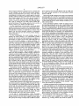
USOO564265 7A
Umted States Patent [19]
[11] Patent Number:
5,642,657
Yeung et al.
[45] Date of Patent:
Jul. 1, 1997
[54] TOASTER WITH COVER FOR REDUCED
[75]
FOREIGN PATENT DOCUMENTS
ENERGY CONSUMPTION
3045598
7/1982
Germany’ ............................... .. 99/391
Inventors: PatH0k_Kw0ng Yeung; Miu_choy
2285389
7/1995 Umted Kingdom .......... .. A47J 37/08
Young; Eric Wah Ho, all of Hong
Kong, Hong Kong
Primary Examiner—Tirnothy F. Simone
Attorney, Agent, or Firm—-Limbach & Limbach L.L.P.
[73] Assignee: SEMK Industrial (Holding) Co. Ltd.,
A toaster having a mechanically actuated cover for each of
one or more toasting volumes. Each cover at least partially
[21] APPI' N04 527,349
[22] Filed:
Se“ 12’ 1995
covers a toasting volume within the toaster during toasting,
thereby reducing heat transfer (primarily due to convection)
[51]
Int. C16 ...... ..
................... .. A47J 37/08
away from the toaster and the object being toasted. In
[52]
US. Cl. ............................... ..
99/334; 99/385; 99/391;
preferred embodiments, each cover is a pair of slidably
99/393
mounted plates. When a carriage (supporting an object to be
[58]
Field of Search ................................ .. 99/329 R, 33 1,
toasted) is manually lowered by a user, a mechanical linkage
99/332, 395, 326-328, 329 P, 329 R1", 334,
335, 339, 337, 340, 335, 389.393, 399,
attached to the carriage cause the plates to slide together to
cover (substantially or totally) a toasting volume. When the
carriage springs up (at the end of the toasting operation), the
mechanical linkage slides the plates away from each other to
401, 402; 219/521, 537, 386, 413
[56]
References Cited
allow removal of the toasted object from the toaster. In other
referred embodiments, each cover is a air of rotatabl
U'S' PATENT DOCUMENTS
Fnounted plates. When a carriage supportling an object
2,997,941
3,760,713
3,789,749
8/1961 Phelan et al. ..
9/1973 Sato ............ ..
2/1974 Paaskesen .
99/391
99/339
99/391
manually lowered by th9 user, a mechanical link?gc attached
t0 the carriage rotates (and optionally also translates) the
plates so that they cover a toasting volume. Then, when the
4,254,695
3/1931 Landry ---- ~
99/334
carriage springs up (at the end of the toasting operation), the
mechanical linkage rotates (or rotates and translates) the
u 99,391
plates 1n the opposrte drrectron to uncover the toasting
volume and allow removal of the toasted ObJCClZ.
lwa'ldry "
,
,
erss
.................. ..
4,972,768 11/1990 Basom San Juan __
5,181,455 1,1993 Masel et aL ________ __
5,216,944
6/1993 Trujillo ....... ..
5,423,246
6/1995 McNair et al.
-
. 219/521
-
-
-
99/385
.. 99/334
14 Claims, 7 Drawing Sheets
-
U.S. Patent
V
/7_
Jul. 1, 1997
Sheet 2 0f 7
C
/
FIG. 3
5,642,657
US. Patent
Sheet 3 0f 7
5,642,657
/ ? ~P f 7 » / A . 7 ~
i;/ 5c/%:
w
Jul. 1, 1997
M:
//
3\
Q\/71?
FIG. 4
r
/
x
A
u
m
wg
US. Patent
Jul. 1, 1997
‘swrli/
ii4!;
Sheet 4 of 7
US. Patent
Jul. 1, 1997
Sheet 5 of 7
5,642,657
US. Patent
Jul. 1, 1997
Sheet 6 of 7
5,642,657
---—115
/-20
[85
\-1 .1514
FIG. .10
FIG. 104
US. Patent
Jul. 1, 1997
Sheet 7 of 7
5,642,657
1
2
TOASTER WITH COVER FOR REDUCED
ENERGY CONSUMPTION
also holes in the sides) of the toaster, the cool air is heated
by the heating element, and the heated air then ?ows out
through the slot above the food. Thus, much heat energy is
wasted (by the mechanism of convective heat loss) due to
FIELD OF THE INVENTION
the stream of hot air which escapes from the toasting
volume.
The energy consumed by a toaster when toasting food is
the product of the average power consumed by the toaster’s
heating elements and the time of the toasting operation. It
The invention relates to improved energy-saving design
for a toaster. The toaster of the invention has a mechanically
actuated cover which is closed during toasting to reduce heat
loss (primarily heat loss due to convection) away from the
object being toasted, and which is opened automatically
after each toasting operation, and/or kept closed until
10
opened in response to manual actuation of a control (e.g., a
would be desirable if ?'re consumed energy could be reduced
without decreasing the energy transferred to the food.
cancellation button) to continuously recycle residual heat
The present invention achieves this objective by reducing
energy within the heating compartment of the toaster after
the energy wasted during a toasting operation by at least
each toasting operation.
15
BACKGROUND OF THE INVENTION
20
25
The invention is a toaster having a mechanically actuated
cover for each toasting volume within the toaster. Each
cover at least partially (and preferably, substantially totally)
covers a toasting volume during toasting, thereby reducing
heat transfer away from the toaster and the object being
toasted. In preferred embodiments, each cover is a pair of
slidably mounted plates (which can but need not be made of
bread caniage closes an electrical switch thereby connecting
a power supply to heating elements within the toaster, and it
also activates a solenoid (23) and a timer. When activated,
the solenoid exerts a magnetic force on elements attached to
elements).
perature (and thus drawing less power), than would be
required in a conventional toaster.
SUMMARY OF THE INVENTION
lowered into a lowered position (in response to manual force
applied by a user). The action of manually lowering the
bread carriage 15 which overcomes the biasing force of
spring 29 and holds bread carriage in the lowered position
(while the bread is toasted by the power-consuming heating
thereby reducing the amount of heat transfer (primarily heat
transfer due to convection) away from the toasting volume.
This allows the inventive toaster to toast food either in less
time, or with heating elements operating at a lower tem
An example of a known toaster is the toaster described in
British Patent Application Publication No. 2,285,3 89A, pub
lished on Jul. 12, 1995, assigned to the assignee of the
present invention. The disclosure of British Patent Applica
tion Publication No. 2,285,389A is incorporated herein by
reference.
The toaster of British Application Publication No. 2,285,
389A has a bread carriage (15) which is biased by a spring
(29) to be in a raised position, but which can be manually
partially covering the toasting volume during toasting,
35
metal or thermally insulating material). When the food
lifting carriage is manually lowered by the user, a mechani
cal linkage attached to the carriage cause the plates to slide
together to at least partially cover a toasting volume. Then,
when the carriage springs up (at the end of the toasting
operation), the mechanical linkage slides the plates away
After being activated at the start of a toasting operation,
the timer generates a signal for deactivating the solenoid, at
the end of a selected period of time (the duration of this time
is determined by manual actuation of a control by a user).
When the solenoid is deactivated by the signal from the
from each other to allow removal of the toasted object from
the toaster. Alternatively, the mechanical linkage slides the
plates away from each other in response to a user’s manual
actuation of a lever after a toasting operation; not automati
cally in response to the carriage springing up at the end of
timer, the carriage rises (in response to the biasing force
the operation.
exerted by spring 29) until an arm (18B) attached to the
In another class of preferred embodiments, each cover is
a pair of rotatably mounted plates (which can but need not
be made of metal or thermally insulating material). When
the food lifting carriage is manually lowered by the user, a
mechanical linkage attached to the carriage rotates (and
optionally also translates) the plates so that they cover a
carriage is caught by a latch (24). In response to this limited
movement of the carriage to an intermediate position
(between the lowered and raised positions), the electrical
45
switch opens (thereby disconnecting the power supply from
the heating elements). While the carriage remains'in the
intermediate position (i.e., while arm 18B is latched by latch
24), the cooling of any toasted food resting on the carriage
50
is slowed, since the food remains near the heating elements
which themselves cool slowly after being disconnected from
the power supply.
toasting volume. Then, when the carriage springs up (at the
end of the toasting operation), the mechanical linkage
rotates (or rotates and translates) the plates in the opposite
direction to uncover the toasting volume and allow removal
of the toasted object. Alternatively, the mechanical linkage
moves the plates away from each other in response to a
toaster, the user manually actuates another control to release 55 user’s manual actuation of a lever after a toasting operation;
When a user wishes to remove the toasted food from the
not automatically in response to the carriage springing up at
the end of the operation.
latch 24. thereby releasing arm 18B and allowing the car
riage to rise (in response to biasing force exerted by spring
29) from the intermediate position to the fully raised posi
The inventive cover can be made of metal or other high
temperature resistant material. When closed, the cover acts
as a barrier to the rising hot air within the toasting volume,
causing the hot air to recirculate back to the heating elements
tion.
During the toasting period (when power is supplied to the
heating elements), the heating elements become hot and
transfer heat to the air surrounding them. The heated air
?ows past the carriage and the food on the caniage, thus
toasting the food In a conventional toaster (which has an
open slot above the food being toasted), a continuous stream
of air ?ows through the toaster (from bottom to top) during
toasting: cool air ?ows in through the bottom (and optionally
and the food being toasted, and reducing the ?ow rate of
incoming cool air through the bottom of the toaster, and the
?ow rate of hot air escaping out through the top of the
65
toaster. In a given time, the heating elements can raise the
recirculated hot air to a higher temperature than the tem
perature to which they could raise an equivalent amount of
5,642,657
3
4
cool air freshly taken in through the bottom of the toaster.
Thus, when used with the inventive closed cover, the heating
position in which the object is within the toasting volume
(e.g., the position shown in FIG. 2), and the carriage is
releasibly latched into the lowered position.
As shown in FIGS. 1-4, the toaster has ‘a chassis (or
“frame”) which includes vertically oriented insulation plates
11, horizontally oriented bottom plate 9 connected between
plates 11, horizontally oriented top insulation member 4
connected between plates 11, end plates 13 (shown in FIGS.
5 and 6) oriented parallel to the plane of FIG. 1, and vertical
coils cause the transfer of more heat to the food while
drawing the same power as heating coils in a conventional
toaster without a cover. Thus, food can be toasted to the
same degree in less time, or in the same time but with less
average power supplied to the heating elements, than in a
conventional toaster. The inventive cover thus increases the
energy efficiency of a toaster.
10
BRIEF DESCRIPTION OF THE DRAWINGS
FIG. 1 is a cross-sectional view (in a ?rst plane) of a ?rst
preferred embodiment of the inventive toaster with bread
carriage 8 in a raised position.
FIG. 2 is a cross-sectional view (in the ?rst plane) of the
?rst preferred embodiment of the inventive toaster, with
bread carriage 8 in a lowered position.
FIG. 3 is a cross-sectional view (in a second plane) of the
?rst preferred embodiment of the inventive toaster with
handle assembly, and the handle assembly is slidably
bread carriage 8 in the raised position.
FIG. 4 is a cross-sectional view (in the second plane) of
the ?rst preferred embodiment of the inventive toaster, with
bread carriage 8 in the lowered position.
FIG. 5 is a perspective view of the toaster of FIGS. 1-4
25
(with enclosure 1. walls 11, and handle 32 removed), with
carriage 8 in the lowered position.
FIG. 7 is a perspective view of a variation on the toaster
of FIGS. 1 and 3, with the bread carriage (within enclosure
1) and handle 32 (rigidly connected to the bread carriage) in
35
FIG. 8 is an end view of the toaster of FIG. 7 (with
enclosure 1 and handle 32 removed), with the bread carriage
latched (by latch 26) in its intermediate position.
FIG. 9 is a cross-sectional view (in a ?rst plane) of a
second preferred embodiment of the inventive toaster with
its bread carriage in a raised position.
FIG. 10 is a cross-sectional View (in the ?rst plane) of the
second preferred embodiment of the inventive toaster, with
its bread carriage in a lowered position.
FIG. 10A is an enlarged detail of a portion of the appa
ratus of FIG. 10.
FIG. 11 is an exploded perspective view of the toaster of
FIGS. 9-10 (with enclosure 110 removed), with the bread
carriage in the lowered position.
FIG. 12 is an exploded perspective view of the toaster of
FIGS. 9-10 (with enclosure 110 removed), with the bread
carriage in the raised position.
DETAILED DESCRIPTION OF THE
PREFERRED EMBODIMENT
described below.
An opening 1A extends through the top surface of enclo
sure 1, and opening 4A extends through member 4. An
object to be toasted (e.g., bread slice 30 or 30') can be
lowered through openings 1A and 4A until it rests on
carriage 8.
When carriage 8 is manually lowered into the lowered
position (of FIGS. 2, 4, and 5), a conventional electrical
switch (not shown) is closed, thereby connecting a power
supply (e.g., power supply 200 shown in phantom view in
FIG. 1) to heating elements 12. Power supply 200 can have
conventional design, but can be selected to be a less expen
sive (and less costly to operate) model that produces lower
output power than would be required to enable a conven
tional
toaster (without covers 14 and 15) to toast bread to the
45
same degree in the same time as can the inventive toaster
(with covers 14 and 15).
The power supply causes electrical current to ?ow
50
through heating elements 12, which raises the temperature
of elements 12, and thus the surrounding air in the toasting
volume between elements 12, to a high temperature. The
heated air toasts an object (e.g., bread slice 30 or 30‘) resting
on carriage 8 in the toasting volume.
Mica holding elements 6 are mounted to the toaster frame,
55 and heating elements 12 are mounted to holding elements 6
in a vertical orientation. Each heating element 12 can be a
mica card having a heating ribbon on the side facing the
bread (not on the other side), or an array of quartz tubes with
a heating ribbon (e. g., a coiled heating wire) inside each tube
and a metal plate attached to the side of the tube array facing
the bread. One heating element 12 is mounted between wire
assembly 2 and a ?rst one of insulation plates 11, and the
other heating element 12 is mounted between wire assembly
A toaster designed in accord with a preferred embodiment
of the invention will be described with reference to FIGS.
1-6. This embodiment has a cover consisting of slidably
mounted metal plates 14 and 15. When bread carriage 8 is
manually lowered by a user (into the position shown in FIG.
2), a mechanical linkage attached to carriage 8 causes plates
14 and 15 to slide together to cover (at least partially) a
toasting volume within the toaster. To toast an object (e.g.,
slice of bread 30 of FIGS. 1, 3, and 4, or slightly larger slice
of bread 30' of FIG. 2) in the toasting volume, the object is
placed on carriage 8, the carriage is lowered into a lowered
mounted to rod 33 of the frame. The handle assembly
comprises handle member 31 (rigidly connected to carriage
8) and a handle attached to an end portion of member 31 (a
handle such as handle 32 shown in FIG. 7). In response to
force exerted on handle 32 (typically by the hand of a human
user), carriage 8 is lowered relative to the frame from the
raised position shown in FIG. 1 (and FIG. 3) to the lowered
position shown in FIG. 2 (and FIG. 4). Carriage 8 is biased
by extension spring 29 (shown in FIGS. 5 and 6) so that it
is normally in the raised position. The action of manually
lowering carriage 8 to the lowered position thus overcomes
the biasing force exerted by spring 29. The mechanism for
releasibly locking carriage 8 in the lowered position will be
FIG. 6 is a perspective view of the toaster of FIGS. 1-4
(with enclosure 1, walls 11, and handle 32 removed), with
carriage 8 in the raised position.
their fully raised position.
rod 33 (shown in FIGS. 5 and 6) attached to one of end
members 13. The frame is mounted within enclosure (or
“housing”) 1, and spacer members 3 are mounted between
enclosure 1 and each plate 11 to stabilize the frame with
respect to enclosure 1.
Carriage 8 within the frame is rigidly connected to a
7 and a second one of insulation plates 11.
65
When carriage 8 is manually lowered into the lowered
position (of FIGS. 2, 4, and 5), an electromagnetic solenoid
(not shown) and a solid state timer (timer 202 shown in
5,642,657
5
6
phantom view in FIG. 1) are activated. The solenoid (and
also the timer, the above-mentioned power supply and
electrical switch, and the below-described mechanical latch)
a unit with lever 49) from the position shown in FIGS. 1 and
3 to the position shown in FIG. 2 or 4. As a result of such
rotation of assemblies 2 and 7, bread slice 30 (or 30‘) on
can be identical to that described in above-referenced British
carriage 8 is ?rmly gripped between (or its motion is
Patent Application Publication No. 2,285,389A. When
activated, the solenoid exerts a magnetic force on handle
member 31 which overcomes the biasing force of spring 29
and holds caniage 8 in the lowered position (while an object
of assembly 2 (which upper end is rotatably attached to
slidably mounted plate 14 by hinge 2A) pulls plate 14 to the
constrained by) assemblies 2 and 7, the upper end of a rod
variations on the embodiment of FIGS. 1-6, the activated
right (from the position shown in FIG. 3 to that shown in
FIG. 2 or 4), and the upper end of a rod of assembly 7 (which
upper end is rotatably attached to slidably mounted plate 15
is toasted by power-consuming heating elements 12). In
solenoid exerts a magnetic force on an element (other than
by hinge 7A) pulls plate 15 to the left (from the position
handle member 31) ?xedly attached to carriage 8 which
overcomes the biasing force of spring 29 and holds carriage
8 in the lowered position.
shown in FIG. 3 to that shown in FIG. 2 or 4).
With a su?iciently thin slice of bread on carriage 8 (e.g.,
slice 30 shown in FIG. 4), the bread slice does not prevent
Each of cover plates 14 and 15 rests on a pair of horizontal
assemblies 2 and 7 from pulling plates 14 and 15 together
until they meet (as shown in FIG. 4). In their position shown
in FIG. 4, plates 14 and 15 completely (or substantially
completely) cover the toasting volume, and heated air within
the toasting volume recirculates dining toasting in the direc
edges of plates 13 of the toaster frame (each plate rests on
two parallel, horizontal edges, each edge on a di?erent one
of plates 13), so that each plate has freedom to slide
horizontally on the edges.
The mechanism for sliding plates 14 and 15 between their
“opened” and “closed” positions includes wire rack assem
blies 2 and 7. spring elements 73 and 74 (shown in FIGS. 1
and 2), levers 48 and 49 and hinges 50 and 51 (shown in
FIGS. 3 and 4). and spring wire 44 (shown in FIGS. 3 and
4). Arm 48A of lever 48 is rigidly attached to wire assembly
2, and arm 49A of lever 49 is rigidly attached to wire
assembly 7. Spring element 73 has one end ?xedly attached
20
slice 30' of FIG. 2, which is thicker than slice 30 of FIG. 4),
the bread slice will engage and stop assemblies 2 and 7 (as
25
to wire assembly 2, and spring element 74 has one end
?xedly attached to wire assembly 7. Each of spring elements
the toaster frame, and that is positioned to be engaged by
central ridge portion 8A of carriage 8. Ann 4813 of lever 48
and arm 49B of lever 49 are also positioned to be engaged
35
While carriage 8 is manually lowered into the lowered
position shown in FIG. 2 (and FIG. 4) in response to
45
engages arm 48B of lever 48 and arm 49B of lever 49, 50
clockwise (away from the positions shown in FIGS. 1 and 3)
assembly 7). When carriage 8 is lowered, wire assembly 2
rotates clockwise and pushes member 46 toward member 47
and wire assembly 7 rotates counter-clockwise and pushes
member 47 toward member 46 (e.g., from the position
shown in FIG. 3 to that shown in FIG. 4), thus causing spring
wire 44 to bend (as shown in FIG. 4). Then (after a toasting
operation) when carriage 8 rises to its fully raised position
(shown in FIG. 3), wire 44 relaxes back to its normal, unbent
position (shown in FIG. 3), thereby separating members 46
and 47 (and thus returning wire assemblies 2 and 7 and
55
described solenoid.
As lever 48 and element 73 rotate clockwise (away from
the positions shown in FIGS. 1 and 3) they exert a clockwise
torque on wire assembly 2 and thus assembly 2 rotates
clockwise (together as a unit with lever 48) from the position
shown in FIGS. 1 and 3 to the position shown in FIG. 2 or
4. Similarly, as lever 49 and element 74 rotate counter
they exert a counter-clockwise torque on wire assembly 7
and thus assembly 7 rotates counter-clockwise (together as
with covers 14 and 15 omitted).
47 (which is in turn ?xedly attached to a rod of wire
user-exerted force on the handle assembly comprising mem
forcing lever 48 to rotate clockwise about hinge 50 (from the
position shown in FIG. 3 to that shown in FIG. 4), and
forcing lever 49 to rotate counter-clockwise about hinge 51
(from the position shown in FIG. 3 to that shown in FIG. 4).
When carriage 8 has been manually lowered into the low
ered position (of FIGS. 2 and 4), it is held in the lowered
position by the downward force exerted by the above
15 (as shown by arrows B in FIG. 2), but much of the air
heated by heating elements 12 recirculates within the toast
ing volume substantially as shown by arrows A of FIG. 4
(and thus energy e?iciency of the toaster is improved
relative to the e?iciency that the FIG. 2 toaster would have
Wire spring 44 is provided for separating wire assemblies
2 and 7 (and thus cover plates 14 and 15) when carriage 8
returns to its fully raised position (shown in FIG. 3). The left
end of spring 44 is attached to member 46 (which is in turn
?xedly attached to a rod of wire assembly 2), the central
portion of member 46 is ?xedly attached to the toaster
frame. and the right end of spring 44 is attached to member
rotatably attached to an end plate 13 of the toaster frame.
Lever 49 is rigidly attached to hinge 51, and hinge 51 is
rotatably attached to the same end plate 13 of the toaster
frame.
ber 31 and handle 32, portion 8A of carriage 8 engages
spring elements 73 and 74, forcing elements 73 and 74 to
rotate (and slightly bend) into the position shown in FIG. 2.
Also while carriage 8 is manually lowered into the lowered
position, handle member 31 (rigidly connected to carriage 8)
shown in FIG. 2) before assemblies 2 and 7 have pulled
cover plates 14 and 15 completely together. In their position
shown in FIG. 2, plates 14 and 15 partially cover the toasting
volume. With plates 14 and 15 partially covering the toasting
volume during toasting, some heated air in the toasting
volume escapes out from the toaster between plates 14 and
73 and 74 also has a free end that is free to move relative to
by a member (e.g., handle member 31) rigidly connected to
carriage 8.
Lever 48 is rigidly attached to hinge 50, and hinge 50 is
tions of arrows A of FIG. 4.
With a su?iciently thick slice of bread on carriage 8 (e.g.,
65
levers 48 and 49 to their vertical orientation as shown in
FIG. 3).
The toaster frame (elements 4, 9, 11, and 13) and cover
plates 14 and 15 are preferably made of plated steel.
Enclosure 1 is preferably made of plated or painted steel, or
(to make the toaster cool to the touch during operation) high
temperature thermal plastic such as polypropylene or poly
carbonate.
In variations on the described toaster, spring elements 73
and 74 are omitted (or levers 48 and 49 and optionally also
spring wire 44 are omitted).
In other variations on the described toaster, the solenoid
is omitted, and instead a mechanical latch means holds an
5,642,657
7
8
element rigidly attached to carriage 8 (such as member 31)
to keep carriage 8 in the fully lowered position during a
toasting period determined by the timer. At the end of the
toasting period, the timer sends a control signal to electrical
circuitry within the toaster to disconnect the power supply
18 is caught by latch 24. Latch 24 thus holds arm 18B (and
the entire carriage assembly) in the intermediate position
shown in FIG. 8.
One end of pin 26 is attached to the upper end of latch 24,
and button 26A (shown in FIG. 7) is attached to the other end
of pin 26. When a user presses button 26A, latch 24 pivots
from heating elements 12. Then, when the user desires to
remove the toasted food, the user manually actuates a
away from arm 18B, thereby releasing the carriage assembly
so that spring 29 pulls the entire carriage assembly up to its
control to release the mechanical latch. thus allowing spring
29 to pull up carriage 8 to the fully raised position (the
upward movement of the carriage opens the cover over the
toasting volume in the manner described above).
In some embodiments of the inventive toaster, the bread
fully raised position.
10
In the embodiment of FIGS. 7 and 8, the carriage assem
bly (including carriage 8) moves only a small distance from
the fully lowered position to the intermediate position, and
the cover (comprising plates 14 and 15) over the toasting
carriage is pulled up (by a spring such as spring 29) from its
fully lowered position all the way to its fully raised position
automatically in response to deactivation or release of the
means (e.g., the above-discussed solenoid or mechanical
volume remains closed even when the carriage has moved to
the intermediate position. This is also true in other embodi
ments of the invention. For example, in an implementation
latch) which had held it in the lowered position during a
of the FIG. 4 embodiment which includes means for relea
toasting operation.
In other embodiments, the toaster includes means for
latching the bread carriage in an intermediate position
(between the lowered and raised positions) in response to
deactivation (or release) of the means which had held it in
the lowered position during a toasting operation. An
example of such an embodiment is that shown in FIGS. 7
and 8. This embodiment is almost identical to that of FIGS.
1-6 (and the elements of the embodiment of FIGS. 7 and 8
that correspond to those of the embodiment of FIGS. 1-6 are
20
sibly latching carriage 8 in an intermediate position, carriage
8 will typically be the position of carriage 8' (shown in
phantom view in FIG. 4), which is only a short distance
above the fully lowered position of carriage 8. When the
latch (not shown in FIG. 4) retains carriage 8 in the
intermediate position, member 31 engages arms 48B and
25
49B and retains them in substantially the position shown in
FIG. 4, and thus spring 44 remains bent (substantially as
shown in FIG. 4) when carriage 8 is in the intermediate
position. Due to its bent con?guration, spring 44 exerts a
numbered identically in FIGS. 1-8). Only those elements of
force on cover plates 14 and 15 which retains cover plates
FIGS. 7 and 8 that have not been described above with
reference to FIGS. 1-6 will be described below.
With reference to FIGS. 7 and 8, carriage 8 within the
14 and 15 in their closed position (shown in FIG. 4) when
carriage 8 is in the intermediate position. Thus, the invention
frame (not shown in FIGS. 7 and 8) is rigidly connected to
a handle assembly slidably mounted to rod 33 of the frame.
The handle assembly comprises member 18 (rigidly con
nected to carriage 8), bracket 19 rigidly attached to member
18), and handle 32 (shown in FIG. 7) which is attached to
protruding arm portion 19B of bracket 19. Extension spring
29 is mounted with its upper end attached to the toaster
frame and its lower end attached to arm 18A of member 18
(so that spring 29 biases member 18 and the bread carriage
attached thereto in their fully raised position). Latch 24 is
hingedly attached to the toaster frame by elbow spring 25.
35
40
ready to remove it from the toaster.
When the user wishes to remove the toasted item from a
toaster whose carriage is in the intermediate position, he or
she manually actuates a release control (e.g., presses a
control such as button 26A on the outside of the toaster), to
release the latch which holds carriage 8 in the intermediate
position, thus triggering the following actions: release of
50
selected time period by manipulating knob 28.
Solenoid 23 is mounted to the toaster frame, and soft iron
plate 22 is mounted to arm portion 19B of bracket 19. When
a user manually lowers handle 32 (and bracket 19, plate 22,
55
carriage in the fully lowered position) and a manually
actuatable release control for releasing the mechanical latch
thereby allowing a spring to pull up the carriage to its fully
raised position, are described in above-referenced British
activates solenoid 23, to cause solenoid 23 to exert a
caniage assembly (carriage 8, handle 32, bracket 19, plate
22, and member 18) in the fully lowered position.
Patent Application Publication No. 2,285 ,389A.
At the end of a toasting operation, a timer (described
29 to pull up the carriage assembly until arm 18B of member
49B in a position keeping the inventive cover closed,
making spring 44 free to relax and thereby open the inven
tive cover (i.e., separate assembly 2 from assembly 7 and
cover plate 14 from cover plate 15).
A suitable mechanical latch for latching the bread carriage
position (after deactivation of a solenoid which had held the
magnetic force on plate 22 thereby holding the entire
heating elements from their power supply, allowing spring
carriage 8 so that it is free to be pulled up by spring 29 to
its fully raised position; and release of the carriage assembly
component (e.g., member 31) which had held arms 48B and
of other embodiments of the invention in an intermediate
member 18, and carriage 8 rigidly attached to handle 32)
into the fully lowered position, a switch (described above)
above) deactivates solenoid 23 and decouples the toaster’s
is in the intermediate position. This has ‘ the bene?t of
keeping the toasted item warm and crisp until the user is
Conventional circuitry, including a power supply (for
heating elements 12), a solenoid, and a timer, is housed in
enclosure 1 in both the embodiments of FIGS. 1-6 and
FIGS. 7-8. At the end of a selected period of time after the
timer is activated (in response to closure of a switch by
movement of the can‘iage assembly to its lowered position),
the timer generates a signal which deactivates the solenoid
(thus allowing the carriage to rise su?iciently far to open the
switch, which in turn disconnects the power supply from the
heating elements). The user selects the duration of the
slows the cooling of a toasted item on carriage 8 (after
toasting), retaining the crispiness of the toasted item for a
longer time, since the entire toasted item remains near
heating elements 12 when the carriage is in the intermediate
position (elements 12 will themselves cool slowly, after they
have been disconnected from the power supply before
carriage 8 enters the intermediate position) and since cover
plates 14 and 15 remain closed thereby causing hot air to
recirculate within the toasting volume even when carriage 8
65
In all variations of the embodiments of FIGS. 1-6 and
7-8, the electric power supplied to the toaster’s heating
elements (e.g., heating elements 12) should be limited so
5,642,657
9
10
that the temperature within each toasting volume, and the
temperature at the toaster components surrounding the toast
ing volume (e.g., at closed plates 14 and 15), during a
freedom to move between a raised position shown in FIG. 9
toasting operation does not increase to a level that would
cause the object being toasted or components of the toaster
(e.g., the closed cover plates) to burn or melt. The material
FIG. 10 (in which the upper ends of slots 115A are stopped
comprising the inventive toaster cover (e.g., the material
comprising slidable plates 14-15, or rotatable plates 80-83
protruding ?om plate 112, with freedom to pivot with
to be described below) should be chosen to retain a desired
amount of heat within the toasting volume. The toaster cover
is made of metal in preferred embodiments, but it can be
(in which the lower ends of slots 115A through plate 115 are
stopped by rivets 114) and the lowered position shown in
by rivets 114).
Each of levers 101 and 102 is mounted to a rivet 99
10
made of non-metallic, thermally insulating material in other
embodiments. The material comprising the inventive toaster
cover should be chosen so that it does not melt or burn
during toasting.
We next describe another embodiment of the inventive 15
toaster with reference to FIGS. 9-12. In this embodiment,
the toaster has two slots (toasting volumes). A cover
designed in accordance with the invention is provided to
cover each slot. Each cover comprises a pair of rotatably
mounted plates (pair of plates 80 and 81 or pair of plates 82
and 83). Each plate is preferably made of metal.
The toaster frame includes vertical side plates 111, end
20
plate 115, with lever 101 ?ee to pivot relative to portion
115B when plate 115 slides relative to plate 112. Pin 102A
protruding ?om lever 102 is attached to bottom right portion
115C of plate 115, with lever 102 ?ee to pivot relative to
portion 115C when plate 115 slides relative to plate 112.
When carriage 108 is manually lowered ?om the FIG. 9
position to the FIG. 10 position, carriage 108 engages levers
101 and 102 and rotates levers 101 and 102 (about rivets 99)
from their positions shown in FIG. 9 to their positions shown
in FIG. 10. Rotating levers 101 and 102 overcome the
biasing force exerted thereon by spring 100, thus displacing
plates 112 and 112' (each ?xedly attached to end plates 111),
horizontal top insulation member 113 connected between
plates 111, and end member 130 ?xedly attached to end plate
112. Two rivets 114 protrude ?om plate 112, and two
identical rivets 114 protrude ?om plate 112'. Two slots 20,
respect to the rivet 99. Spring 100 is attached between levers
101 and 102. Spring 100 exerts a biasing force on levers 101
and 102 tending to separate the levers and thus to maintain
the levers in the FIG. 9 orientation. Pin 101A protruding
from lever 101 is attached to bottom left portion 115B of
25
which de?ne tracks along which bread carriage 108 moves,
extend through each of plates 112 and 112'. Two rivets 99
spring 100 into the position shown in FIG. 10. Also when
levers 101 and 102 rotate into their FIG. 10 position, pins
101A and 102A pull plate 115 down to its lowered position
shown in FIG. 10 (until rivets 114 stop further downward
motion of plate 115 relative to plate 112).
This downward motion of plate 115 causes cover plates
80, 81, 82, and 83 to rotate into their closed positions (shown
in FIGS. 10 and 11) in which plates 80 and 81 cover the
toasting volume on the toaster’s left side and plates 82 and
83 cover the toasting volume on the toaster’s right side. The
manner in which this is accomplished will be described with
protrude ?om plate 112, a lever 101 is mounted to one of
rivets 99, and a lever 102 is mounted to the other of rivets
99. Similarly, two rivets 99 (not shown) protrude ?om plate
112', a lever 101 (not shown) is mounted to one of these
rivets 99, and a lever 102 (not shown) is mounted to the
other of rivets 99.
35 reference to FIG. 10A, which is an enlarged view of a
Enclosure 110 (not shown in FIGS. 11 and 12) sm'rounds
the frame. The ?ame and cover plates 80, 81, 82, and 83 are
portion of the FIG. 10 apparatus.
preferably made of plated steel. Enclosure 110 is preferably
portion 80A protruding ?om each end of the central portion.
Plate 80 consists of a ?at central plate portion, and ?at rod
made of plated or painted steel, or (to make the toaster cool
to the touch dining operation) high temperature thermal
The ?at surface of each rod portion 80A is oriented at an
40
plastic such as polypropylene or polycarbonate.
Carriage 108 (shown in phantom view in FIGS. 9 and 10)
is sized and shaped to support two slices of bread (one in
each toasting volume), and is mounted within the frame with
?eedom to move relative to the frame along slots 20. One
end of carriage 108 (the end that rides in slots 20 in plate
45
are ?ee to rotate but not translate relative to the toaster
mounted to end member 130. In response to force exerted on
50
Each plate 115 has four curved slots (85, 86, 87, and 88)
extending therethrough. As best shown in FIG. 10A, slot 85
provides a track along which rod portion 80A of cover plate
80 “rides” (slot 87, identical to slot 85, provides a track
along which rod portion 82A of plate 82 rides) when plate
115 translates up or down relative to the toaster frame, and
55
slot 86 provides a track along which rod portion 81A of
cover plate 81 rides (slot 88, identical to slot 86, provides a
track along which rod portion 83A of plate 83 rides) when
plate 115 translates up or down relative to the toaster ?ame.
When levers 101 and 102 pull down plates 115 into the
position shown in FIG. 10 (and FIG. 10A), the downward
moving plates 115 rotate cover plates 80, 81, 82, and 83 until
the cover plates reach their closed positions shown in FIG.
10 and FIG. 10A (by the action of slots 85, 86, 87, and 88,
on rod portions 80A, 81A, 82A, and 83A, respectively, as
This means is preferably identical to the means (described
above with reference to FIGS. 1-6 or FIGS. 7-8) for
performing the corresponding functions in the embodiment
of FIGS. 1-6 or FIGS. 7-8, and the description thereof will
not be repeated with reference to FIGS. 9-12.
The toaster of FIGS. 9-12 also includes two plates 115,
each slidably mounted to one of end plates 112 and 112' with
?at central plate portion with a ?at rod portion (81A, 82A,
and 83A, respectively) protruding ?om each end of the
central portion. End portions 80A, 81A, 82A, and 83A are
rotatably mounted to the toaster frame (so that plates 80-83
frame).
112) is rigidly connected to a handle assembly (which
includes member 131), and the handle assembly is slidably
the handle assembly (typically by the hand of a human user),
carriage 108 is lowered relative to the frame ?om the raised
position shown in FIG. 9 to the lowered position shown in
FIG. 10. Carriage 108 is biased by an extension spring (not
shown. but which is preferably identical to spring 29 of the
embodiment of FIGS. 5 and 6) to be normally in the raised
position. The action of manually lowering carriage 108 to
the lowered position thus overcomes the biasing force
exerted by the spring. A means for releasibly locking car
riage 108 in the lowered position (and/or in an intennediate
position after release ?om the lowered position) is provided.
acute angle relative to the central portion (as best shown in
FIG. 10A). Each of plates 81, 82, and 83 also consists of a
the rod portions ride along the slots to the outer ends of the
65
slots).
When carriage 108 is released (so that its bias spring pulls
it up to the FIG. 9 position, spring 100 relaxes to its FIG. 9
5,642,657
12
11
period after entry of the mechanical link assembly into
the ?rst con?guration, wherein the carriage assembly
position, thereby returning levers 101 and 102 to their FIG.
9 position. As levers 101 and 102 return to their FIG. 9
enters the raised position automatically thereby causing
position, pins 101A and 102A push plates 115 up to their
raised position. The upward-moving plates 115 rotate cover
plates 80, 81, 82, and 83 until the cover plates reach their
opened positions shown in FIG. 9 (by the action of slots 85,
86, 87, and 88. on rod portions 80A, 81A, 82A, and 83A,
the mechanical link assembly to enter the second
con?guration in response to assertion of the timer
signal.
3. The toaster of claim 1, also including:
respectively, as the rod portions ride along the slots to the
inner ends of the slots). With the covers opened, toasted
bread can be removed from the bread carriage.
In variations on the embodiment of FIGS. 9-12, when the
heating elements;
bread carriage is manually lowered by the user, other
power supply means for supplying power to the heating
elements in response to entry of the mechanical link
assembly into the ?rst con?guration, and for decou
pling the power from the heating elements in response
mechanical linkages attached to the carriage rotate a pair of
to a timer signal generated upon termination of a
cover plates so that they cover a toasting volume. Then,
toasting period- after entry of the mechanical link
assembly into the ?rst con?guration;
carriage biasing means for urging the carriage assembly to
the raised position;
latch means for releasibly holding the carriage assembly
in the lowered position in response to the carriage
assembly moving to said lowered position;
when the carriage springs up (after a toasting operation), the
mechanical linkages rotate the plates in the opposite direc
tions to uncover the toasting volume and allow removal of
the toasted object.
Various other modi?cations and alterations in the appa
ratus of the invention will be apparent to those skilled in the
art. Although the invention has been described in connection
with speci?c preferred embodiments, it should be under
latch release means for releasing said latch means in
response to an external force applied after assertion of
stood that the invention as claimed should not be unduly
the timer signal, thereby allowing the carriage biasing
limited to such speci?c embodiments.
What is claimed is:
1. A toaster, including:
a frame enclosing a toasting volume, wherein the frame
de?nes an opening for admitting an object into the
25
4. The toaster of claim 1, wherein the cover substantially
totally covers the opening when the mechanical link assem
bly is in the ?rst con?guration.
toasting volume;
5. The toaster of claim 1, wherein the frame also encloses
a second toasting volume and the frame also de?nes a
a carriage assembly;
a member rigidly attached to the carriage assembly,
wherein the member is translatably engaged with the
frame so that the carriage assembly is movable relative
to the frame between a raised position and a lowered
position in the toasting volume in response to transla
tion of the member relative to the frame;
a mechanical link assembly having a ?rst con?guration
and a second con?guration, wherein the mechanical
link assembly enters the ?rst con?guration in response
to the carriage assembly moving to the lowered posi
tion and engaging a portion of said mechanical link
assembly, and wherein the mechanical link assembly
40
second opening for admitting a second object into the
second toasting volume, and wherein the toaster also
includes:
a second mechanical link assembly having a ?rst member
attached to the carriage assembly, wherein the second
mechanical link assembly enters a ?rst con?guration in
response to the carriage assembly moving to the low
ered position, and wherein the second mechanical link
assembly enters a second con?guration in response to
the carriage assembly moving to the raised position;
and
a second cover attached to the second mechanical link
enters the second con?guration in response to the
carriage assembly moving to the raised position; and
means to move the carriage assembly to the raised
position.
45
assembly, wherein the second mechanical link assem
bly holds the second cover in a ?rst position at least
a cover attached to the mechanical link assembly, wherein
the mechanical link assembly holds the cover in a ?rst
partially covering the second opening when the
mechanical link assembly is in the ?rst con?guration,
position at least partially covering the opening when
and wherein the second mechanical link assembly
holds the second cover in a second position uncovering
the mechanical link assembly is in the ?rst
con?guration, and wherein the mechanical link assem
bly holds the cover in a second position uncovering the
opening when the mechanical link assembly is in the
second con?guration, wherein the cover includes a ?rst
plate slidably mounted to the frame and a second plate
slidably mounted to the frame, and wherein the
mechanical link assembly includes:
means for sliding the ?rst plate and the second plate
55
bottom end positioned for engagement by the carriage
assembly when said carriage assembly moves into the
into positions at least partially covering the opening
lowered position, wherein the ?rst subassembly moves
the ?rst plate into a position at least partially covering
the opening in response to the carriage assembly engag
ing the bottom end of the ?rst subassembly when said
carriage assembly moves into the lowered position; and
a second subassembly movably mounted to the frame and
having a top end connected to the second plate and a
in response to movement of the carriage assembly
into the lowered position.
2. The toaster of claim 1, also including:
heating elements; and
power supply means for supplying power to the heating
elements in response to entry of the mechanical link
assembly into the ?rst con?guration. and for decou
pling the power from the heating elements in response
to a timer signal generated on termination of a toasting
the second opening when the second mechanical link
assembly is in the second con?guration.
6. The toaster of claim 1, wherein the means for sliding
the ?rst plate and the second plate includes:
a ?rst subassembly movably mounted to the frame, and
having a top end connected to the ?rst plate and a
65
bottom end positioned for engagement by the carriage
assembly when said carriage assembly moves into the
lowered position, wherein the second subassembly
5,642,657
14
13
rotatably mounted to the frame, and wherein the
moves the second plate into a position at least partially
covering the opening in response to the carriage assem
bly engaging the bottom end of the second subassembly
when said carriage assembly moves into the lowered
position.
5
7. The toaster of claim 6, wherein the ?rst subassembly
includes:
a hinge means rotatably mounted to the frame;
a ?rst lever arm having one end attached to the hinge
mechanical link assembly includes:
means for rotating the ?rst plate and the second plate
into positions at least partially covering the opening
in response to movement of the carriage assembly
into the lowered position, wherein the means for
rotating the ?rst plate and the second plate includes:
a sliding plate slidably mounted to the frame,
wherein there is a ?rst slot and a second slot in
said sliding plate, the ?rst plate has an end portion
which extends through the ?rst slot, and the sec
a second lever arm having one end attached to the hinge
ond plate has an end portion which extends
means and whose opposite end is said bottom end of the
through in the second slot.
?rst subassembly; and
10. The toaster of claim 9, wherein the end portion of the
a wire assembly rigidly attached to the ?rst lever arm and 15 ?rst plate is rotatably mounted to the frame, the end portion
having an upper portion which is said top end of the
of the second plate is rotatably mounted to the frame,
?rst subassembly.
wherein the sliding plate translates in response to movement
8. The toaster of claim 7, wherein the second subassembly
of the carriage assembly into the lowered position thereby
includes:
causing the ?rst slot to rotate the end portion of the ?rst plate
a second hinge means rotatably mounted to the frame; 20 in a ?rst rotational direction as said end portion of the ?rst
means;
10
plate rides in the ?rst slot during said translation, and
a third lever arm having one end attached to the hinge
causing the second slot to rotate the end portion of the
second plate in a second rotational direction as said end
means
a fourth lever arm having one end attached to the second
portion of the second plate rides in the second slot during
hinge means and whose opposite end is said bottom end
of the second subassembly; and
25 said translation.
11. A toaster, including:
a second wire assembly rigidly attached to the third lever
a frame enclosing a toasting volume, wherein the frame
arm and having an upper portion which is said top end
de?nes an opening for admitting an object into the
of the ?rst subassembly, and wherein the means for
toasting volume;
sliding the ?rst plate and the second plate also includes:
spring means attached between the wire assembly and 30
‘
the second wire assembly, for exerting a biasing
force urging said wire assembly away from said
second wire assembly and thus the ?rst plate away
from the second plate, wherein said wire assembly
to the frame between a raised position and a lowered
and said second wire assembly overcome said bias- 35
ing force and move together in response to move
ment of the carriage assembly into the lowered
position.
9. A toaster, including:
a ?ame enclosing a toasting volume, wherein the frame
de?nes an opening for admitting an object into the
tion of the member relative to the frame;
a pair of cover plates movably mounted to the frame; and
means for moving the cover plates into a ?rst con?gura
con?guration uncovering the opening in response to
a carriage assembly;
45
movement of the carriage assembly into the raised
position, wherein the cover plates are slidably mounted
to the frame, and wherein the means for moving the
cover plates is a mechanical link assembly including:
means for sliding the cover plates into the ?rst con
to the frame between a raised position and a lowered
position in the toasting volume in response to transla
tion of the member relative to the frame;
a mechanical link assembly having a ?rst con?guration
and a second con?guration, wherein the mechanical
position in the toasting volume in response to transla
tion at least partially covering the opening in response
to movement of the carriage assembly into the lowered
position, and for moving the cover plates into a second
toasting volume;
a member rigidly attached to the carriage assembly,
wherein the member is translatably engaged with the
frame so that the carriage assembly is movable relative
a carriage assembly;
a member rigidly attached to the carriage assembly,
wherein the member is translatably engaged with the
frame so that the carriage assembly is movable relative
?guration in response to movement of the carriage
50
assembly into the lowered position.
12. The toaster of claim 11, wherein the cover plates
substantially totally cover the opening when in said ?rst
con?guration.
link assembly enters the ?rst con?guration in response
to the can‘iage assembly moving to the lowered posi
13. The toaster of claim 11, wherein the cover plates
tion and engaging a portion of said mechanical link 55 include a ?rst plate and a second plate, and wherein the
assembly, and wherein the mechanical link assembly \ means for sliding the cover plates includes:
enters the second con?guration in response to the
a ?rst subassembly movably mounted to the frame, and
carriage assembly moving to the raised position; and
having a top end connected to the ?rst plate and a
bottom end positioned for engagement by the carriage
a cover attached to the mechanical link assembly, wherein
assembly when said carriage assembly moves into the
the mechanical link assembly holds the cover in a ?rst
lowered position, wherein the ?rst subas sembly moves
position at least partially covering the opening when
the ?rst plate into a position at least partially covering
the mechanical link assembly is in the ?rst
the opening in response to the carriage assembly engag
con?guration, and wherein the mechanical link assem
ing the bottom end of the ?rst subassembly when said
bly holds the cover in a second position uncovering the
opening when the mechanical link assembly is in the
second con?guration, wherein the cover includes a ?rst
plate rotatably mounted to the frame and a second plate
65
carriage assembly moves into the lowered position; and
a second subassembly movably mounted to the frame and
having a top end connected to the second plate and a
5,642,657
15
16
bottom end positioned for engagement by the carriage
assembly when said carriage assembly moves into the
lowered position, wherein the second subassembly
moves the second plate into a position at least partially
covering the opening in response to the carriage assem
bly engaging the bottom end of the second subassembly
when said carriage assembly moves into the lowered
position. wherein the ?rst subassembly includes:
a hinge means rotatably mounted to the frame;
a ?rst lever arm having one end attached to the hinge 10
mounted to the frame, and wherein the means for
means;
moving the cover plates is a mechanical link assembly
a second lever arm having one end attached to the hinge
means and whose opposite end is said bottom end of
including:
means for rotating the cover plates into the ?rst con
the ?rst subassembly; and
a wire assembly rigidly attached to the ?rst lever arm 15
and having an upper portion which is said top end of
the ?rst subassembly.
14. A toaster, including:
assembly into the lowered position, wherein the
a sliding plate slidably mounted to the frame,
wherein there is a ?rst slot and a second slot in
toasting volume;
to the frame between a raised position and a lowered
?guration in response to movement of the carriage
cover plates include a ?rst plate and a second plate,
and wherein the means for rotating the cover plates
includes:
a frame enclosing a toasting volume, wherein the frame
de?nes an opening for admitting an object into the
a carriage assembly;
a member rigidly attached to the carriage assembly,
wherein the member is translatably engaged with the
frame so that the carriage assembly is movable relative
position in the toasting volume in response to transla
tion of the member relative to the frame;
a pair of cover plates movably mounted to the frame; and
means for moving the cover plates into a ?rst con?gura
tion at least partially covering the opening in response
to movement of the carriage assembly into the lowered
position, and for moving the cover plates into a second
con?guration uncovering the opening in response to
movement of the carriage assembly into the raised
position, wherein the cover plates are rotatably
said sliding plate, the ?rst plate has an end portion
which extends through the ?rst slot, and the sec
ond plate has an end portion which extends
25
through in the second slot.