1
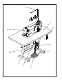
175 176 179 Spezialnähmaschine Betriebsanleitung D Instruction manual GB Postfach 17 03 51, D-33703 Bielefeld • Potsdamer Straße 190, D-33719 Bielefeld Telefon +49 (0) 521 / 9 25-00 • Telefax +49 (0) 521 / 9 25 24 35 • www.duerkopp-adler.com Ausgabe / Edition: 10/2010 Änderungsindex Rev. index: 02.0 Printed in Federal Republic of Germany Teile-Nr./Part.-No.: 0791 175740 Alle Rechte vorbehalten. Eigentum der Dürkopp Adler AG und urheberrechtlich geschützt. Jede, auch auszugsweise Wiederverwendung dieser Inhalte ist ohne vorheriges schriftliches Einverständnis der Dürkopp Adler AG verboten. All rights reserved. Property of Dürkopp Adler AG and copyrighted. Reproduction or publication of the content in any manner, even in extracts, without prior written permission of Dürkopp Adler AG, is prohibited. Copyright © Dürkopp Adler AG - 2010 Foreword This instruction manual is intended to help the user to become familiar with the machine and take advantage of its application possibilities in accordance with the recommendations. The instruction manual contains important information on how to operate the machine securely, properly and economically. Observation of the instructions eliminates danger, reduces costs for repair and down-times, and increases the reliability and life of the machine. The instruction manual is intended to complement existing national accident prevention and environment protection regulations. The instruction manual must always be available at the machine/sewing unit. The instruction manual must be read and applied by any person that is authorized to work on the machine/sewing unit. This means: – – – Operation, including equipping, troubleshooting during the work cycle, removing of fabric waste, Service (maintenance, inspection, repair) and/or Transport. The user also has to assure that only authorized personnel work on the machine. The user is obliged to check the machine at least once per shift for apparent damages and to immediatly report any changes (including the performance in service), which impair the safety. The user company must ensure that the machine is only operated in perfect working order. Never remove or disable any safety devices. If safety devices need to be removed for equipping, repairing or maintaining, the safety devices must be remounted directly after completion of the maintenance and repair work. Unauthorized modification of the machine rules out liability of the manufacturer for damage resulting from this. Observe all safety and danger recommendations on the machine/unit! The yellow-and-black striped surfaces designate permanend danger areas, eg danger of squashing, cutting, shearing or collision. Besides the recommendations in this instruction manual also observe the general safety and accident prevention regulations! General safety instructions The non-observance of the following safety instructions can cause bodily injuries or damages to the machine. 1. The machine must only be commissioned in full knowledge of the instruction book and operated by persons with appropriate training. 2. Before putting into service also read the safety rules and instructions of the motor supplier. 3. The machine must be used only for the purpose intended. Use of the machine without the safety devices is not permitted. Observe all the relevant safety regulations. 4. When gauge parts are exchanged (e.g. needle, presser foot, needle plate, feed dog and bobbin) when threading, when the workplace is left, and during service work, the machine must be disconnected from the mains by switching off the master switch or disconnecting the mains plug. 5. Daily servicing work must be carried out only by appropriately trained persons. 6. Repairs, conversion and special maintenance work must only be carried out by technicians or persons with appropriate training. 7. For service or repair work on pneumatic systems, disconnect the machine from the compressed air supply system (max. 7-10 bar). Before disconnecting, reduce the pressure of the maintenance unit. Exceptions to this are only adjustments and functions checks made by appropriately trained technicians. 8. Work on the electrical equipment must be carried out only by electricians or appropriately trained persons. 9. Work on parts and systems under electric current is not permitted, except as specified in regulations DIN VDE 0105. 10. Conversion or changes to the machine must be authorized by us and made only in adherence to all safety regulations. 11. For repairs, only replacement parts approved by us must be used. 12. Commissioning of the sewing head is prohibited until such time as the entire sewing unit is found to comply with EC directives. 13. The line cord should be equipped with a country-specific mains plug. This work must be carried out by appropriately trained technicians (see paragraph 8). It is absolutely necessary to respect the safety instructions marked by these signs. Danger of bodily injuries ! Please note also the general safety instructions. Index Page: Part 2: Installation instructions class 175 176 179 – Original Instructions 1 Scope of delivery . . . . . . . . . . . . . . . . . . . . . . . . . . . . . . . . . . . . . . . . . . . . . . 3 2 General notes and securing devices . . . . . . . . . . . . . . . . . . . . . . . . . . . . . . . . . . 3 3 Assembling the stand 3.1 3.2 3.3 3.4 Assembling the stand components . . . . Completing the table top with the control Self-manufacture of the table top . . . . . Setting the working height . . . . . . . . . . . . . . . . . . and fastening . . . . . . . . . . . . . . . . . . . it . . . . . . to the . . . . . . . . . . . . stand . . . . . . . . . . . . . . . . . . . . . . . . . . . . . . . . . . . . . . . . . . . . . . . . . . . . . . . . . . . . . . . . 4 5 5 6 4 4.1 4.2 4.3 4.4 Sewing drives Drive category, type and use . Mounting the control. . . . . . . Mounting the set value initiator Mounting the pedal . . . . . . . . . . . . . . . . . . . . . . . . . . . . . . . . . . . . . . . . . . . . . . . . . . . . . . . . . . . . . . . . . . . . . . . . . . . . . . . 7 8 8 9 5 5.1 5.2 Mounting the machine head Fitting the machine head . . . . . . . . . . . . . . . . . . . . . . . . . . . . . . . . . . . . . . . . . . Earthing . . . . . . . . . . . . . . . . . . . . . . . . . . . . . . . . . . . . . . . . . . . . . . . . . . . . 10 11 6 6.1 6.2 6.3 6.4 Connecting the sewing drive Connecting the sewing drive to the mains . . . . . . . . Mounting the sewing lamp (optional equipment) . . . Connecting the control DA220C . . . . . . . . . . . . . . Setting the machine-specific parameters . . . . . . . . . . . . 12 12 13 14 7 Pneumatic connection . . . . . . . . . . . . . . . . . . . . . . . . . . . . . . . . . . . . . . . . . . . 15 8 Lubrication . . . . . . . . . . . . . . . . . . . . . . . . . . . . . . . . . . . . . . . . . . . . . . . . . . 16 9 Sewing test . . . . . . . . . . . . . . . . . . . . . . . . . . . . . . . . . . . . . . . . . . . . . . . . . . 17 . . . . . . . . . . . . . . . . . . . . . . . . . . . . . . . . . . . . . . . . . . . . . . . . . . . . . . . . . . . . . . . . . . . . . . . . . . . . . . . . . . . . . . . . . . . . . . . . . . . . . . . . . . . . . . . . . . . . . . . . . . . . . . . . . . . . . . . . . . . . . . . . . . . . . . . . . . . . . . . . . . . . . . . . . . . . GB 1 2 3 10 4 5 9 8 7 6 1 Scope of delivery The scope of delivery is dependent on your order. Prior to setting up, please check that all required parts are present. This description is valid for a special sewing machine the individual components of which are completely delivered by Dürkopp Adler AG. Equipment: – – – – – – – – – – 1 2 3 4 5 6 7 8 9 10 Yarn stand Table top Control with main switch Maintenance unit Pedal rods Pedal Set value initiator (packed with the control unit) Drawer Stand Machine head with sewing drive GB 2 General notes and securing devices ATTENTION ! The special sewing machine must only be assembled by trained specialists. Securing devices If you have bought an assembled special sewing machine, the following securing devices have to be removed: – Tapes and battens at machine head, table and stand. 3 3 Assembling the stand 3.1 Assembling the stand components 1 15 14 13 14 13 2 3 12 11 10 4 5 9 6 8 7 – – – – – 4 Mount the individual parts of the stand as shown in the illustration. Push the attached four stand feet 6 on. Slightly loosen the screws 4 on both sides of the cross struts 7 to ensure the stability of the stand. The stand must rest on the floor with all four feet! Tighten the screws 4 again. Screw on holder 8 for the oil can at the left stand spar. 3.2 Completing the table top with the control and fastening it to the stand – – – – – – – – Insert the machine head support 15 into the bore of the table top. Insert the rubber supports 14 for the machine head into the recesses of the table top 12. Insert rubber corners 13. Screw drawer 11 with its holders underneath the table top on the left. Screw cable duct 10 underneath the table top at the back. Punch-mark the positions of the screw connections of the oil drip pan 2 and fasten it with wood screws under the cutout of the table top. Fasten the table top 12 with wood screws (B8 x 35) on top of the stand. The alignment on the stand is specified by the measurements indicated in the sketch. Insert the yarn stand 1 into the bore of the table top and fasten it with nuts and washers. Mount and align yarn stand and thread guiding arm. The yarn stand and the thread guiding arm must be positioned vertically on top of each other. 1 0 0 m m 5 0 0 m m GB 6 7 m m 1 0 6 0 m m 3.3 Self-manufacture of the table top If you manufacture the table top yourself, please take the measurements from the illustrations on page 18. 5 3.4 Setting the working height 1 1 – – – – 6 The working height can be adjusted between 750 and 900 mm (measured up to the top edge of the table top). Loosen screws 1 at the spars of the stand. Adjust the table plate horizontally to the required working height. To prevent tilting, pull the table plate out or push it in by the same distance on both sides. Fasten both screws 1. 4 Sewing drives 4.1 Drive category, type and use The following sewing drives are available: Subclass Clutch motor Clutch positioning drive DC positioning drive 0175-141621 Efka DC1500/DA220C 0176-141621 Efka DC1500/DA220C 0179-171629 Efka DC1500/DA220C GB 7 4.2 Mounting the control 8 1 7 2 6 3 4 5 – – Mount the control unit 1 with 4 screws under the table top 8. Fasten the power supply cable of the control unit with the strain relief clamp under the table top. 4.3 Mounting the set value initiator – – 8 Screw angle 7 under the table top 8. Screw the set value initiator 2 on angle 7. 4.4 Mounting the pedal – – – – – – Fasten pedal 5 on the stand strut 4. Align pedal 5 as follows for ergonomical reasons: The center of the pedal has to be approximately under the needle. The stand strut 4 is equipped with slotted holes for aligning the pedal. Hang in the pedal rods 3. Loosen screw 6 slightly. Adjust the height of the pedal rods 3 as follows: The discharged pedal 5 should have an inclination of approx. 10°. Tighten screw 6. GB 9 5 Mounting the machine head 5.1 Fitting the machine head ATTENTION! Remove the supporting screws at the front and in the center before tilting the machine head into the working position. – – – Insert machine head 1 in tilted position into the cutout of the table top. Remove the support screws 2 at the front and in the center. Remove the safety bar 3. 1 2 3 10 5.2 Earthing 1 2 3 GB The earthing wire on the sewing machine head bleeds off static charges of the machine head via the motor control unit to the mass. – – Fasten the earthing wire 3 to the provided connection at the control unit. Guide the earthing wire 3 upwards and fasten it with screw 1 and flat connection 2 to the base plate of the machine. 11 6 Connecting the sewing drive 6.1 Connecting the sewing drive to the mains ATTENTION ! Work of every kind on the electric equipment of the special sewing machine must only be carried out by electricians or correspondingly trained personnel. The mains plug has to be pulled out! The manufacturer’s operating instructions enclosed to the sewing drive have to be observed in any case! 6.2 Mounting the sewing lamp (optional equipment) See instructions 0791 100700. 12 6.3 Connecting the control DA220C 1 2 B41 B 4 1 M B80 B2 B 2 B 8 0 M E B ... A B 1 8 B 7 7 6 L S M ... V 8 . . B776 A GB – – – – – – Plug the cable of the reference value transmitter (pedal) into bushing B80 of the control. Plug the cable of the motor sensor 1 into bushing B2 of the control. Plug the cable 2 of the motor into bushing B41 of the control. Plug the cable to the sewing machine into bushing A of the control. Run all cables through the cable duct. Cable of the control panel (optional equipment) into bushing B776. 13 6.4 Setting the machine-specific parameters 6.4.1 General notes The functions of the sewing-drive control are determined by the program and the parameter settings. All parameter values for the relevant machine class and subclass are pre-set by Efka prior to delivery of the sewing drives. For each class and subclass some parameters at technician and manufacturer level must be changed so that the control is perfectly adapted to the machine. The parameters concerned are listed in the parameter sheet (in the accessory pack). The parameter 290 (selection of the machine class) has to be set to the appropriated value in the “manufacturer level” (see parameter sheet 9800 331101 PB30). Please take the detailed description of the control from the attached current operating instructions of the motor manufacturer (see also www.efka.net). 6.4.2 Autoselect By measuring the Autoselect resistance in the machine, the control “recognizes” which machine series is connected. By means of Autoselect control functions and the preset values of the parameters are selected. If no Autoselect resistance or an invalid one is recognized by the control, the drive will only run with the so-called emergency operation functions in order to protect the machine from being damaged. 14 7 Pneumatic connection ATTENTION ! The pneumatic units will only operate properly at a supply pressure of 8 to 10 bar. The sewing machine’s operating pressure is 6 bar. 1 2 3 6 4 8 2 10 4 Pneumatic connection package Under the order number 0797 003031 a pneumatic connection package for stands with compressed air maintenance unit is available. It includes the following components: – Connecting hose, 5 m long Ø = 9 mm – Hose nozzles and hose clamps – Coupling socket and connector plug – Maintenance unit with manometer and pressure regulator Connecting the compressed air maintenance unit – Fasten the compressed air maintenance unit 2 to the stand strut with angle, screws and flap. – Connect the compressed air maintenance unit to the compressed air supply with connecting hose 4 (Ø = 9 mm) and hose coupling R1/4". Setting the operating pressure The operating pressure is 6 bar. It can be read off at manometer 3. For adjusting the operating pressure raise and turn handle 1. Increase the pressure = Turn twist handle 1 clockwise Reduce the pressure = Turn twist handle 1 counter-clockwise 15 GB 8 Lubrication 4 5 6 7 Caution: Risk of injury ! Oil may cause skin eruption. Avoid a longer contact with the skin. Wash yourself thoroughly after a contact. ATTENTION ! The handling and disposal of mineral oils is subject to legal regulation. Deliver used oil to an authorised collection point. Protect your environment. Take care not to spill oil. Oil the special sewing machine exclusively with lubricating oil DA 10 or an equivalent oil with the following specification: – Viscosity at 40° C: 10 mm²/s – Ignition point: 150° C DA 10 can be bought at the sales points of DÜRKOPP ADLER AG under the following parts numbers: 250 ml container: 9047 000011 1-litre container: 9047 000012 2-litre container: 9047 000013 5-litre container: 9047 000014 Maintenance work to be done Explanation hours Lubrication of the machine head The check of the oil supply is limited to the following items: - Fill the oil reservoir 4 up to the marking “Max” with the machine standing upright. - Check the oil reservoir in the hook drive casing 6 and fill up oil, if necessary. For this purpose screw out screw 5. When the machine is tilted to the back, the oil level must not drop below the lower long marking 7 of the inspection glass. The oil level must not exceed the upper marking. 16 Operating 8 9 Sewing test After finishing the assembly work a sewing test has to be made. – Plug in the mains plug. Caution: Risk of injury ! Switch the main switch off. Thread in needle thread and looper thread only with the sewing machine switched off. – – – – – – – Thread in needle thread and looper thread (see operating instructions). Switch the main switch on. Select the material to be processed. Make the sewing test first at low speed and then at continuously increasing speed. Check whether the seams correspond to the desired requirements. If the requirements are not met, alter the thread tensions (see operating instructions). If necessary, also check the adjustments indicated in the service instructions and correct them, if required. 17 GB Table top cutout 18