1
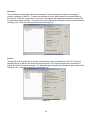
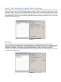
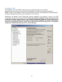
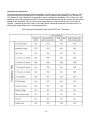
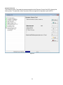
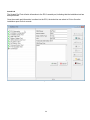
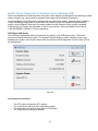
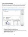
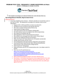
® ® Bendix ACom Diagnostics Software 6.7 User Guide 1 Contents General Informa on .......................................................................................................................................................... 3 RP1210 Adapters................................................................................................................................................................ 4 PC Hardware Requirements ............................................................................................................................................... 5 Technical Assistance ........................................................................................................................................................... 5 Installing Bendix® ACom® Diagnos cs ............................................................................................................................... 6 Using Bendix® ACom® Diagnos cs ..................................................................................................................................... 7 Bendix® ACom® Diagnos c Windows 6.7 Screen ECU Status Screen .............................................................................. 10 Diagnos c Trouble Code (DTC) Screen ............................................................................................................................. 11 Wheel Speed Sensor Screen ............................................................................................................................................ 12 Configura on Screen ....................................................................................................................................................... 13 Bendix® Trailer Roll Stability Program (TRSP) Screen ....................................................................................................... 14 Pressures Screen .............................................................................................................................................................. 16 Bendix® Trailer Roll Stability Program (TRSP) Sensors ..................................................................................................... 17 Sensor Calibra on ............................................................................................................................................................ 18 Component Test Screen ................................................................................................................................................... 19 Bendix® Trailer Roll Stability Program (TRSP) (If Equipped) ............................................................................................. 21 Installa on Test ................................................................................................................................................................ 22 Bendix® ACom® Diagnos cs 6.7 Adap ve Cruise w/Braking (ACB) ................................................................................. 35 ACB Data Log .................................................................................................................................................................... 39 2 This guide, as well as the so ware described in it, is furnished under license and may only be used or copied in accordance with the terms of the license. Please contact the Bendix Tech Team for a copy of such license. The information provided in this manual is for informational purposes only and is subject to change without notice and should not be construed as a guarantee by Bendix Commercial Vehicle Systems LLC (“Bendix”). Bendix assumes no responsibility or liability for any errors or inaccuracies that may appear in this publication nor within the software itself. User is using the software “as-is”, “whereis” with no warranty implied or otherwise. At no time shall Bendix be liable to user for any direct, special, indirect, consequential, liquidated, punitive, or progressive damages relative to the use of the software hereunder. General Information Bendix® ACom® diagnostics will provide the technician with the capability to configure and troubleshoot Bendix components. This application will support the following Bendix® products: Bendix® EC-60™ electronic controller Bendix® EC-80™ electronic controller Bendix® Wingman® active cruise with braking Bendix™ VORAD® VS400 radar system Bendix® FLC20 camera system Bendix™ SmarTire® Tire Pressure Monitoring System (TPMS) Bendix® Trailer-Link™ System Bendix® Tractor Lift Axle ABS module Bendix® TABS-6™ Trailer ABS module Bendix® TABS-6™ Advanced trailer ABS module Bendix® TABS-6™ Advanced MC™ trailer ABS module Bendix® TABS-6™ Advanced MV™ trailer ABS module Bendix® EC-30™electronic controller Bendix® EC-17™ electronic controller Bendix® EC-30T™ electronic controller Bendix® MC-30™ electronic controller Bendix® A-18™ electronic controller Bendix® Gen 4 (U1x) electronic controller Bendix® Gen 5 (U12 and U16) electronic controller 3 RP1210 Adapters The Bendix® ACom® Diagnostic software relies on RP1210 compliant hardware adapters for communication. A list of the recommended adapters is shown below. NOTE: ACom® Diagnostics will remain in the demo mode unless there is at least one RP1210 driver installed on the computer. What follows is a list of supported hardware adapters for the software. Before using this software, verify that the driver (.dll) for the adapter to be used for communications is already loaded on the computer and is the latest version available from the adapter manufacturer. NAVCom/NAVLink Volvo 88890020 Nexiq USB‐Link Nexiq Bluetooth USB‐Link Nexiq PLC Adapter Noregon DLA+ Noregon DLA+PLC Noregon UDIF PLC/J1708 JPRO DLA+PLC Cummins Inline 5 Cummins Inline 6 Dearborn DPA4+ Dearborn DPA5 Dearborn PLC TestCon (may be available in a kit with DPA4+) Note: Adapters that interface using serial or parallel ports to the laptop are no longer supported. 4 PC Hardware Requirements Bendix® ACom® diagnostic software will run on Windows Vista, Windows 7 and Windows 8 operating systems. Below are the minimum requirements for running the application. • 1 Gigahertz (GHz) or faster 32-bit (x86) or 64-bit (x64) processor • 2 GB RAM • 1 GB free disk space • Microsoft Internet Explorer 8+ • Adobe Acrobat (latest version recommended) • USB Communication port • VGA standard graphics adapter with a resolution of 800 x 600 (minimum), 1024 x 768 recommended • Windows compatible keyboard and mouse NOTE: Windows 95, 98 and XP operating systems are not supported. The content displayed on an ACom Diagnostic screen depends on: the ECU selected on the Start page; and also on the features enabled on the ECU. Certain features/options of ACom Diagnostics may not be visible, since they do not apply to the ECU being inspected. For extended details on the features of a particular ACom Diagnostics screen, select the Help button located on that screen. Technical Assistance For any questions regarding setup or operation of ACom® Diagnostics please contact Bendix at 1-800-AIR-BRAKE (1-800-247-2725). See the Bendix website, www.bendix.com for periodic software updates. Licensing Information BENDIX® “ACom® Diagnostic software” requires an end user license agreement, including user consent, prior to installing the software on the user’s computer. 5 Installing Bendix® ACom® Diagnostics When installing Bendix® ACom® Diagnostics it is recommended that all other programs be closed. ACom Diagnostics will be installed using a setup wizard, during which the technician will need to acknowledge various questions for the installation to continue. Figure 1 The Bendix ACom Diagnostics software is installed to the default location of C:\Bendix\ACom Diagnostics. During installation of ACom Diagnostics 6.7, several applications will be installed and several installation windows will appear. If there are any older versions of ACom Diagnostics on the computer ACom® Diagnostics will un-install the older versions. ACom Diagnostics 5.12 will also be installed with the ACom® Diagnostics 6.7. After a period of time, a pop-up box will be displayed indicating that the installation was successful. Figure 2 Next the Setup wizard will report that the setup is completing and allow the technician to launch the ACom® Diagnostics tool. 6 Using Bendix® ACom® Diagnostics An icon will be placed on the desktop. Double click the icon or select the ACom Diagnostics application from the Bendix install directory or Program group to launch the program. A Starter screen will appear. The starter screen has various features: 1. The desired Communication adapter can be selected by clicking the icon depicting a computer and tractor/trailer. (See the arrow shown in Figure 4.) Selecting this icon opens up the driver selection for the RP1210 adapter. Check the box next to the adapter you will use, then press the green checkbox to confirm. Figure 3 Figure 4 7 2. The entry screen allows the technician to Start with ECU, if the technician knows which ECU they are diagnosing. See Figure 4. Select from the list on the Starter screen and press the Start with ECU button. 3. Alternatively, the program will detect the ECU. The screen will indicate which Bendix ECU was found and the technician can select Launch to start Bendix® ACom® Diagnostics. Figure 5 4. Any ECU can be displayed in the DEMO mode by pressing the Start in Demo mode button. The Demo mode allows the technician to investigate the program’s features without communicating with an actual ECU. Figure 6 8 The following ECU controllers are supported by Bendix® ACom® 6.7 diagnostic software on the ACom 6.7 CD: Bendix® EC-60™ electronic controller Bendix® EC-80™ electronic controller Bendix® Wingman® active cruise with braking Bendix™ VORAD® VS400 radar system Bendix® FLC20 camera system Bendix™ SmarTire® Tire Pressure Monitoring System (TPMS) Bendix® Trailer-Link™ System Bendix® Tractor Lift Axle ABS module Bendix® TABS-6™ Advanced trailer ABS module Bendix® TABS-6™ Advanced MC™ trailer ABS module Bendix® TABS-6™ Advanced MV™ trailer ABS module Additionally, Bendix® ACom® diagnostic software 5.12 is included on the ACom® 6.7 CD and will support the following: Bendix® TABS-6™ trailer ABS module Bendix® EC-30™electronic controller Bendix® EC-17™ electronic controller Bendix® EC-30T™ electronic controller Bendix® MC-30™ electronic controller Bendix® A-18™ electronic controller Bendix® Gen 4 (U1x) electronic controller Bendix® Gen 5 (U12 and U16) electronic controller If you have any questions about the operation of ACom® Diagnostics 5.12, open the ACom Diagnostics 5.12 User Guide PDF available on the Bendix web site (www.bendix.com). 9 Bendix® ACom® Diagnostic Windows 6.7 Screen ECU Status Screen Refer to the Service Data sheet for the system being diagnosed for all cautions and warnings; certain system changes (e.g. sensor position changes) require approval from Bendix Engineering. Bendix® ACom® Diagnostics opens, by default, to the Electronic Control Unit (ECU) status screen. This screen provides the technician with a snap-shot of the ECU. In the System Data field, the following information is displayed: system name, part number, serial number, software version, ABS configuration, odometer, whether Bendix® Trailer Roll Stability Program (TRSP) is enabled or disabled and ADL program. Additionally, in the Status field, the voltage and the number of active Diagnostic Trouble Codes (DTCs) − if any − are displayed. Figure 7 From the ECU Status screen the technician can open the DTC screen by either double clicking on the ABS lamp or selecting the DTC button. The technician can also open the Wheel Speed Sensor or Configuration screens by selecting the appropriate button. Control Buttons for ECU Status The DTC will open the DTC screen The Wheels will open the wheel speed sensor screen The Config will open the configuration screen The Help will open the Help page for ECU Status The Close will close the screen 10 Diagnostic Trouble Code (DTC) Screen The DTC screen provides the technician with active, inactive and event history information. For the active DTC information, the screen is divided into three panes. The first pane displays the active DTCs, the second pane displays troubleshooting/repair information corresponding to the active DTC; and the third pane displays the connector with pin-out so the technician can troubleshoot the active DTC. Additionally, a count of the number of occurrences of the DTC, and odometer readings of the first and last occurrence of the DTC and the current odometer reading are provided. Figure 8 The event history screen displays information for: configuration change events; the history of cleared events; end of line test complete, and more. Figure 9 Control Buttons for DTC screen The Service button will open the Service Data sheet for the ECU. The Repair button will open the repair file for wheel speed sensors only. The Read button will read the information from the ECU. The Clear button will clear the information from tab and a pop-up box will confirm that the ECU has processed the request. Click the pop-up to acknowledge. The Report button opens a screen for the technician to generate a DTC report, additionally, the technician can select to save, email or print DTC reports. The Help button opens help page for the DTC screen. The Close button closes the DTC screen. 11 Wheel Speed Sensor Screen The wheel speed sensor screen allows the technician to spin the wheels and record the sensor output. Addi onally, there is a sensor air gap field which indicates the speed when the sensor starts registering speed. A lower air gap speed value (e.g. 3 to 4) indicates a properly adjusted wheel speed sensor. An air gap speed value higher than 5 indicates that the wheel speed sensor needs to be adjusted by installing the sensor closer to the tone ring elimina ng the distance between the sensor and tone ring. Figure 10 Control buttons for graph: The Start button will start the data collection. The Stop button will stop the data collection. The Rewind button will rewind the data. The Forward button will forward the data. The graph display can be a line graph (default), a bar graph, or 3D‐style graph. Control Buttons for Wheel Speed The Open File button will open an existing wheel speed file. The Load File button will load an existing wheel speed file. The Help button will open the Help page. The Close button will close the screen. 12 Configuration Screen The Configura on screen provides the technician with the following informa on: ABS configura on, Load and Sensor, TRSP (if equipped), ADL, AUX I/O and Broadcast op ons. ABS Configura on ABS Configura on provides the technician with the number of sensors and modulators the ECU is currently configured to expect. Vehicle Data provides the technician with vehicle type, the number of axles, and the ECU orienta on. Odometer displays the odometer, trip and service odometer. Tire size [RPM] / Tone Ring displays the stored re size and tone ring size. Figure 11 Load and Sensor Configuration The Sensors field provides the technician with information on how the external load sensor (if equipped) is configured. The Bogie Load field shows the expected weight for the rear axle − empty and fully loaded. The Miscellaneous field shows the wheel track width and number of lift axles. The Lateral Acceleration Sensing field provides whether the sensing type is internal or external (if equipped). The Load Sensing field displays the sensing type (internal or external) and displays the detected air bag pressures. Figure 12 13 Bendix® Trailer Roll Stability Program (TRSP) Screen Note: TRSP screen will be available if the Electronic Control Unit (ECU) supports TRSP. The TRSP window allows the technician to check if TRSP is enabled, the TRSP module position, and the TRSP parameters. Figure 13 Auxiliary Design Language (ADL) The ADL screen allows the technician to verify if the ECU has an auxiliary design language program stored for a specific operation. This screen is read only. Figure 14 14 AUX I/O The AUX I/O screen allows the technician to see how the ECU’s auxiliary inputs and outputs are configured. This screen is read only. Figure 15 Broadcast The Broadcast screen allows the technician to see which J2497 and J1939 messages are (or are not) enabled. Figure 16 Control Buttons for Configuration Screens • The Modify button will open the change screen • The Save button will save the configuration file of the ECU • The Help button will open the HELP page • The Close button will close the screen 15 Pressures Screen The Pressures screen allows the technician to view and record pressures supplied by the trailer ABS system. The table below describes which pressures are reported by supported Electronic Control Units (ECUs). The pressures screen allows the technician to apply the brakes and monitor the pressures. Figure 17 Control Buttons for Graph: • The Start button will start the data collection • The Stop button will stop the data collection • The Rewind button will rewind the data • The Forward button will forward the data • The graph display can be a line graph (default), a bar graph, or 3D-style Control Buttons for Pressure Screen: • The Open file button will open an existing pressure file • The Load file button will load an existing pressure file • The Help button will open the Help page • The Close button will close the screen 16 Bendix® Trailer Roll Stability Program® (TRSP) Sensors NOTE: The TRSP sensors will only be available if the ECU supports TRSP. The TRSP sensors allow the technician to monitor the lateral acceleration sensor, axle load and installation angle data. Figure 18 Control Buttons for Graph: • The Start button will start the data collection • The Stop button will stop the data collection • The Rewind button will rewind the data • The Forward button will forward the data • The graph display can be a line graph (default), a bar graph or 3D-style graph Control Buttons for TRSP Sensors: • The Open File button will open an existing TRSP file • The Load File button will load an existing TRSP file • The Help button will open the Help page • The Close button will close the screen 17 Sensor Calibration The Sensor Calibration page allows the Lateral Acceleration Sensor (LAS) to be calibrated. The trailer needs to be on a level surface for the calibration. Press “Start” to begin the calibration process, use the “Yes, No, or Cancel” choices to answer any questions. Bendix® ACom® Diagnostics software can be used to recalibrate the lateral acceleration sensor, clear any DTCs and display the actual sensor value. Figure 19 Control Buttons for TRSP Sensors: • The Start button starts the calibration • The Yes button is used to acknowledge that the technician is in agreement with the question asked • The No button is used when the technician disagrees with the question asked • The Cancel button stops the calibration • The Close button closes the calibration window 18 Component Test Screen The Component Test screen allows the technician to test various components of the system such as: wheel speed sensors; modulators; pressure sensors; switches; and the Bendix® Trailer Roll Stability Program (TRSP) system. The Component Test screen also allows the technician to perform system tests such as: battery voltage; ABS indicator lamp; Aux I/O; and axle load. Note: Before performing the component test, make sure the vehicle is parked on a level and flat ground with the wheels chocked. Figure 20 The Component test screen supports various tests; each tab will be populated with the tests which are supported by the ECU. The tabs are Sensors, Modulators, Pressures, TRSP system (if equipped) and Miscellaneous. Select the appropriate tab and the left side of the screen will display a list of available tests. Upon selecting the test, the right side of the screen will show what the technician must do before the test can run. Figure 21 Control Buttons for Component Test • • • • • The Start/Next button will start the test and/or move the technician to the next step of the test The Stop button will stop the test The Service Data button will open the service data sheet The Help button will open Help The Close button will close the screen 19 Modulators This test allows the technician to check the modulators. The test displays the number of modulators currently configured in the ECU. To select the modulator to check, simply press the Start/Next button to start the test. Follow the instructions on the screen. The program will prompt the technician by asking “Did the modulator respond correctly?” The technician should respond by selecting the green check mark button indicating “yes”, or the red circle with a line button indicating “no.” Figure 22 Pressure This test will allow the technician to test the various pressure sensors supported by the ECU. Press the Start/Next button to start the test and follow the instructions. The program will prompt the technician by asking “Did the ECU respond correctly?” The technician should respond by selecting the green check mark indicating “yes”, or the red circle with a line indicating “no.” Figure 23 20 Bendix® Trailer Roll Stability Program (TRSP) (If Equipped) Note: TRSP will be available only if the Electronic Control Unit (ECU) supports TRSP. This test will allow the technician to check the TRSP sensor installation angle. To begin, the technician will need to select “installation angle”, then press the Start/Next button to begin the test. Follow the prompts to run the test. The program will prompt the technician by asking, “Did the ECU respond correctly?” The technician must then acknowledge if the test was successful by selecting the green check mark indicating “yes”, or the red circle with a line indicating “no.” Figure 24 Miscellaneous This test will allow the technician to evaluate the battery voltage, ABS indicator lamp, and AUX I/O functions. The function will display the tests available which are supported by the ECU. The technician must select which function(s) to check, then press the Start/Next button to start the test. Follow the prompts to complete the evaluation. The program will prompt the technician by asking, “Did the ECU respond correctly?” The technician must acknowledge by selecting the green check mark indicating “yes”, or the red circle with a line indicating “no.” Figure 25 21 Installation Test The Installation Test is for OEMs to make end-of-line verification tests on new vehicles. The test allows the technician to verify the proper installation of the ECU and system components. NOTE: In order for the Installation Test to run, the technician must first acknowledge the system-generated warning indicating that the vehicle must be parked on a level surface. Additionally, the Bendix® ACom® Diagnostics software Installation Test provides a check of the ABS components with the help of technician input. Please note that the Installation Test is intended as a tool to assist the quality control process at the vehicle manufacturer. However, this test must not be relied on as the sole validation check of proper brake system installation. The vehicle manufacturer must ensure appropriate process controls are in place in the manufacturing process to completely validate the vehicle brake system prior to vehicle shipment. Figure 26 22 Customize The Customize screen allows the technician to customize some of the features in the installation test. Warning: The tests conducted must match the features of the vehicle being tested. With each vehicle, it is important to confirm that the correct sets of features are being verified. Typically the Bendix® ACom® Diagnostics software will save the features used on the previous test, so if the software was used on a vehicle with different features during its last use, the customized features must be re-assessed and changed to match the new vehicle. To complete any necessary changes, simply click in the box next to a desired test name — a check mark will appear — to request that the test be performed. Similarly, you may uncheck boxes to skip those tests. Mandatory tests are displayed on the screen in gray, optional tests appear in black. You may use the screen to: • Re-arrange the order of the tests • Save a report in TXT or HTML format • Save a report using the VIN as the filename • Create a folder in which to save the report (the program will prompt to ask for a folder and file name) • Select to show wheel speeds in either MPH or RPM • Select if you wish the test sequence to stop if the previous test failed • Select if the technician needs to confirm if the service brake is applied during the modulator test Figure 27 Control Buttons for Customize • • • • The OK button is used to accept changes The Cancel button is used to cancel (not accept) changes The Up button moves highlighted test up the list The Down button moves highlighted test down the list If there are any active Diagnostic Trouble Codes (DTCs) on the Electronic Control Unit (ECU), the installation will not run, and the technician will be notified by a message. Active DTCs must be corrected and cleared before the Installation Test can be performed. 23 Installation Test requirements The chart below indicates which tests are available for an Electronic Control Unit (ECU). If there is a YES next to the test name, that specific test is required in order to complete the Installation Test. If there is a “NO” shown for a test, that test is not required in order to complete the Installation Test. If there is an “N/A” shown for a test, this indicates that the ECU does not support that specific test. As a result, the test will not appear in the Installation Test list. For the wheel speed sensors, at least one of the two sensor tests is required – indicated by the word “ONE” in the chart. Bendix recommends that the full sensor test be run, although the simple sensor test is an acceptable option. All the tests in the table below refer to Bendix® EC-60™ Controllers. 24 ECU Information The ECU Information Test is a mandatory test. It must always be run. The test provides the technician with information about how the ECU is configured. Figure 28 25 Installation Configuration The Installation Configuration field displays a graphic – and specifics – about the expected configuration. The technician must verify that the components have been installed as shown. Figure 29 26 Axle Load Test The Axle Load Test is mandatory for the Bendix® TABS-6™ Advanced (ADV) Electronic Control Unit (ECU), but not when inspecting the Bendix® TABS-6™ Multi-Voltage (MV) ECU. This test displays the detected weight on the rear axle in pounds. Figure 30 27 Battery Voltage Test The Battery Voltage Test checks the voltage measured at the Electronic Control Unit (ECU), with the modulators de-energized, energized and de-energized. The voltage operating range is 8.0 VDC to 32.0 VDC for Bendix® TABS-6™ ADV / MV and MC controllers. Figure 31 28 ABS Indicator Lamp Test The ABS Indicator Lamp Test will illuminate and then extinguish the ABS indicator lamp while the technician verifies the correct operation of the dash-mounted ABS indicator lamp. Figure 32 29 Installation Angle Test The Installation Angle Test displays the vertical angle of the mounted ECU. The vertical angle must be within ±5 degrees of vertical. NOTE: The installation angle test will only be available if the ECU supports Bendix® Trailer Roll Stability Program (TRSP). Figure 33 30 Sensor Tests The Wheel Speed Sensor output is tested using the screen shown below. Figure 34 31 Pressure Sensor Test The Pressure Sensor Test reads the pressures applied to the Electronic Control Unit (ECU) through the brake system. The potential number of pressure sensors supported is dependent upon the ECU. Figure 35 32 P21 / P22 Delivery Test The P21/P22 Delivery Test will check that the module is correctly plumbed to the brake chambers and test the brake delivery air pressure. Park the vehicle on level ground and chock the wheels. During this test, the delivery pressure should match the control pressure. After applying the brakes, the technician must verify that the delivery and control pressures are the same. Bendix® ACom® Diagnostics system will then release the brakes and the technician must verify that the brakes have released. The final step is for the Bendix ACom Diagnostics software to re-apply the brakes. Figure 36 33 Scratch Pad The Scratch Pad Test will write information to the ECU’s scratch pad, indicating that the installation test has been performed. Once the scratch pad information is written into the ECU, the technician can select to Print or Save the installation report for their records. Figure 37 34 Bendix® ACom® Diagnostics 6.7 Adaptive Cruise w/Braking (ACB) Refer to the Bendix Service Data sheet for the system under diagnosis for all cautions and warnings; certain system changes (e.g. sensor position changes) require approval from Bendix Engineering. Launch the Bendix ACom Diagnostics software and using the starter window, select Wingman (Adaptive Cruise with Braking) diagnostics. In cases where the license key has been loaded into the Windows® registry, select Wingman Data Log in the starter window and the Wingman Data Log will be available. If the license key is known, but not loaded, or the key is not known, contact the Bendix Tech Team at 1-800-AIR-BRAKE (1-800-247-2725) for assistance. ACB Status-ACB Sensor The ACB Data Log selection takes the technician, by default, to the ACB status screen. This screen provides information about the system. The System Data field displays: model, software version, and software part number. In the System Status field, the number of active Diagnostic Trouble Codes (DTCs) will be displayed. Figure 38 Control Buttons for ACB Status • • • • The DTC button will open the DTC window The Config button will open the Configuration window The Help button will open the Help page for ACB Status The Close button will close the window 35 Diagnostic Trouble Code (DTC) Window‐ACB Sensor The DTC screen provides the technician with active and stored DTC information. For the active and stored DTC information, the windows are two tabs; switch between the two views by clicking on the tab. Each page has two panes: the first pane displays the DTCs; and the second pane displays troubleshooting/repair information corresponding to the DTC. The DTC window will display the SPN (Suspect Parameter Number), FMI (Failure Mode Identifier), Error Object, Failure Number, Description and Frequency Counter (number of occurrences the fault). Figure 39 Control Buttons for DTC window • • • • • • The Read button will refresh the DTC information from the ECU The Clear button will clear the information from the tab The Report button opens a page to allow the technician to input data about the ECU and then allows the technician to save, email or print a DTC report The Service button opens the service data The HELP button opens help page for DTC The Close button will close the window 36 Configuration Window – ACB The Configuration Window is used to display ACB sensor configuration information including the mounting offset, stationary object warning, alignment value and following distance setting configuration number. ACB Sensor Configuration Mounting Offset The ACB Sensor mounting offset provides the horizontal offset relative to the vehicle’s longitudinal axis. A positive value indicates an offset to the left of the vehicle’s longitudinal axis (driver’s side) and a negative value indicates an offset to the right of the vehicle’s longitudinal axis (passenger side). The offset range is ± 500 mm (19.69 inches). The physical mounting location of the sensor cannot exceed ± 500 mm. Changes to the sensor location from the OEM-installed position requires Bendix Engineering approval. Stationary Object Warning The Stationary Object Warning field provides the technician with an audible alert for stationary objects within the vehicle path. Stationary object warnings will be enabled (ON) or disabled (OFF). Alignment Value The ACB sensor alignment value provides the angle calculated by the system that the sensor is found to be pointed (laterally) away from the vehicle’s longitudinal axis. The smaller the alignment angle, the better forward vehicle tracking performance. A positive value indicates that the sensor is currently aimed to the right side of the vehicle’s longitudinal axis (passenger side). A negative value indicates the sensor is currently aimed to the left side of the vehicle’s longitudinal axis (driver’s side). The acceptable alignment range is ± 1.4 degrees, but if the alignment value is greater than ±0.8 degrees, it is recommended to adjust the sensors aim. See the ACB Service Data Sheet for full details of the sensor adjustment procedures. Figure 40 37 Following Distance Settings The Following Distance/alerts configuration number is a numeric value that represents the current configuration of the ACB sensor following distance setting and alerts. Control Buttons for Configuration • • • The Modify button will open the change window, allowing the technician to reset the alignment value to zero and change the alert following distance configuration number. Additionally, the technician is permitted to save or load the ACB sensor configuration file. The Help button will open the HELP page The Close button will close the window Figure 41 Control Buttons for Change Configuration • • • • • The Write button writes the configuration changes to the ACB sensor The Save File button saves the configuration file of the ACB sensor The Load File button loads the configuration file of the ACB sensor The Help button will open the HELP page The Close button will close the window 38 ACB Data Log The Wingman® Data Log on the Bendix® ACom® Diagnostics starter window allows the technician to create an ACB data log report or clear the resettable data log file. Figure 42 Creating Data Log Report When the technician selects Create Data Log Report, a dialogue box will open, requesting the mileage and VIN of the vehicle. Input the information and select Continue. Figure 43 Next the technician should select: Print; Print Preview; Email to Bendix; or, Save the report. If the technician chooses to save the report, a dialogue box opens allowing them to choose the file location. Figure 44 39 Clear Rese able Data Log When Clear Resettable Data Log is chosen, a dialogue box will open and request that the technician confirm the resettable data log file is to be cleared. Next, a dialogue box will open asking the technician if they want to save the resettable data log before clearing it. If the technician selects “Yes”, a dialogue box will open asking the technician to input the mileage and VIN. A Data Log Report will be created and the technician will be asked if they want to: Print; Print Preview; Email to Bendix; or Save. If the technician selects “No” to saving the report before it is cleared, or after the report is created, Bendix® ACom® Diagnostics system will clear the Resettable Data Log. Bendix Commercial Vehicle Systems LLC • 901 Cleveland Street • Elyria, Ohio • www.bendix.com BW2668 © 2014 Bendix Commercial Vehicle Systems LLC, a member of the Knorr-Bremse Group • 08/2014 • All Rights Reserved 40