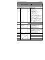
1
2404
2408
CONTROL SETPOINT
PROGRAMMER
ENG
Installation and operation
handbook
Installation and Operation Handbook
Contents
MODELS 2408 and 2404 PID CONTROLLERS
INSTALLATION AND OPERATION HANDBOOK
Contents
Page
Chapter 1
INSTALLATION .................................................................1-1
Chapter 2
OPERATION ......................................................................2-1
Chapter 3
ACCESS LEVELS..............................................................3-1
Chapter 4
TUNING..............................................................................4-1
Chapter 5
PROGRAMMER OPERATION ..........................................5-1
Chapter 6
CONFIGURATION .............................................................6-1
Chapter 7
USER CALIBRATION ........................................................7-1
Appendix A
UNDERSTANDING THE ORDERING CODE ................... A-1
Appendix B
SAFETY and EMC INFORMATION.................................. B-1
Appendix C
TECHNICAL SPECIFICATION……….……………………C-1
Appendix D
LOAD CURRENT MONITORING AND DIAGNOSTICS..D-1
Appendix E
PROFIBUS COMMUNICATIONS….……………………....E-1
“This product is covered by one or more of the following US Patents:
5,484,206; Additional patents pending.
PDS and INSTANT ACCURACY are trademarks of Eurotherm.”
Issue 10 of this handbook applies to software version 4.
Issue 10.0 Nov-04
Applies to 2408 and 2404 controller software version 4.0
i
Contents
Installation and Operation Handbook
Enhancements to Software Version 4
The following enhancements have been added to software versions 4.
•
Isolated Single Logic Output Module
•
Transducer Power Supply Module to provide 5 or 10Vdc to an external transducer. (Not
intended for melt pressure control)
•
DeviceNet communications
•
Linear over range limits are +5% of high instrument range and –5% of low instrument
range for all process input ranges (i.e. 0-20mA, 4-20mA, 0-10V)
•
Sensor break or input open circuit faults are detected on all analogue inputs (PV1.PV2
and remote input channels)
•
PV2 alarm, full scale high and low limits default to maximum and minimum display
limits
•
Deviation alarms are not inverted when direct acting control is selected. Alarm
behaviour when using reverse acting control is unchanged
•
The PD track valve positioning parameter (Pd.tr) has been removed
Controllers Affected:Standard controllers – which include
programmers with up to 4 programs
Version 4.11 or later
Setpoint programming controllers with up to
20 programs
Version 4.61 or later
Profibus controllers – which include
programmers with up to 4 programs
Version 4.32 or later
•
The 10Amp output relay in module 4 is not available on controllers supplied after Jan 04
Related Information
•
•
•
DeviceNet Communications Handbook part no. HA027506 which includes the
parameter address map.
Profibus Communications Handbook part no. HA026290
EMC (Electromagnetic Compatibility) Installation Guide, part no. HA025464
These are available on www. eurotherm.co.uk.
ii
Issue 10.0 Nov-04
Applies to 2408 and 2404 controller software version 4.0
Installation and Operation Handbook
Installation
Chapter 1 INSTALLATION
Terminal covers
Sleeve
Ratchets
Display screen
Label
Panel retaining clips
Latching ears
Panel sealing gasket
Figure 1-1 2408 1/8 DIN controller
Sleeve
Terminal covers
Ratchets
Display screen
Label
Panel retaining clips
Latching ears
Panel sealing gasket
Figure 1-2 2404 1/4 DIN controller
2408 and 2404 Controller
1-1
Installation
Installation and Operation Handbook
Outline dimensions Model 2408
48mm
1.89in
150mm
5.91in
Panel
cut-out
2408
OP 1 OP2
92 x 45mm
96mm
3.78in
-0
+0.8
-0
+0.6
3.62x1.77in
SP2
-0
+0.03
REM
AUTO RUN
MAN HOLD
-0
+0.02
Figure 1-3
Outline dimensions of Model 2408 controller
10mm
(0.4in)
Recommended
minimum spacing
of controllers
Outline dimensions Model 2404
96mm
3.78in
38mm
(1.5in)
(Not to
scale)
150mm
5.91in
2404
OP 1
OP2
SP2
REM
96mm
3.78in
AUTO
MAN
RUN
HOLD
Panel cut-out
92 x 92 mm
-0
+0.8
-0
3.62 x 3.62 in +0.03
Recommended
minimum
10mm
spacing of
(0.4in)
controllers
38mm
(1.5in)
(Not to
scale)
Figure 1-4 Outline dimensions Model 2404 controller
The electronic assembly of the controller plugs into a rigid plastic sleeve, which in turn fits
into the standard DIN size panel cut-out shown in Figures 1-3 and 1-4.
1-2
2408 and 2404 Controller
Installation and Operation Handbook
Installation
INTRODUCTION
Models 2408 and 2404 are high stability, temperature or process controllers with self and
adaptive tuning. They have a modular hardware construction which accepts up to three plugin Input/Output modules and two interface modules to satisfy a wide range of control
requirements. Two digital inputs and an optional alarm relay are included as part of the fixed
hardware build.
The instruments are available as:
• standard controllers - which include a basic 8-segment programmer
Models 2408/CC and 2404/CC
• setpoint programming controllers:
Models 2408/CP, P4, CM and
2404/CP, P4, CM
• motorised valve controllers - which include a basic 8-segment programmer
Models 2408/VC and 2404/VC
• setpoint programming motorised valve controllers:
Models 2408/VP, V4, VM and
2404/VP, V4, VM
Before proceeding, please read the chapter called, Safety and EMC Information.
Controller labels
The labels on the sides of the controller identify the ordering code, the serial number, and the
wiring connections.
Appendix A, Understanding the Ordering Code, explains the hardware and software
configuration of your particular controller.
MECHANICAL INSTALLATION
To install the controller
1. Prepare the control panel cut-out to the size shown in Figure 1-3, or 1-4.
2. Insert the controller through the panel cut-out.
3. Spring the upper and lower panel retaining clips into place. Secure the controller in
position by holding it level and pushing both retaining clips forward.
Note: If the panel retaining clips subsequently need removing, in order to extract the
controller from the control panel, they can be unhooked from the side with either your fingers,
or a screwdriver.
Unplugging and plugging-in the controller
If required, the controller can be unplugged from its sleeve by easing the latching ears
outwards and pulling it forward out of the sleeve. When plugging the controller back into its
sleeve, ensure that the latching ears click into place in order to secure the IP65 sealing.
2408 and 2404 Controller
1-3
Installation
Installation and Operation Handbook
NEW SLEEVE DESIGN MKIII
From Jan-03 an improved design of 1/8 DIN long sleeve is shipped with all new 2408
controllers and indicators. (The month and year of manufacture are shown in the last two
pairs of digits of the instrument serial number).
Details
A new sealing gasket will be fitted onto the instrument bezel !. This gasket replaces the
gasket which was moulded into the front of the sleeve of all previous instruments.
The gasket previously moulded into the sleeve where it fits behind the panel is now supplied
as a separate item ".
Reasons for the Change
This change is to ensure that IP65 sealing is reliably achieved and less physical effort is
required to insert the instrument into the new sleeve.
Recommendations
1.
2.
An instrument delivered after Jan 03 should be used with the sleeve supplied
If the instrument is required to replace one already in use, the existing sleeve should
also be replaced
3. A new instrument can be fitted into an existing sleeve by carefully removing gasket
! but IP65 sealing will not be maintained
4. An existing instrument can be fitted into a new sleeve but IP65 sealing will not be
maintained
It is, however, possible to achieve IP65 sealing for 3 and 4 above. A gasket kit is available by
quoting Part No SUB24/GAS2408.
Then:5. To fit a new instrument in an older sleeve carefully remove gasket !. Replace it
with the thinner (1.25mm) gasket from the kit
6. To fit an existing instrument into a new sleeve fit the thicker (1.6mm) gasket from
the kit between the instrument and the sleeve
The seal " supplied as a separate item with a new instrument, should be placed over the
sleeve prior to mounting it through the panel cut out as shown below:Panel
New
Instrument
Sleeve seal "
(supplied as a
separate item)
Instrument
sleeve
New gasket ! fitted onto bezel
1-4
2408 and 2404 Controller
Installation and Operation Handbook
Installation
ELECTRICAL INSTALLATION
This section consists of five topics:
• Rear terminal layouts
• Fixed connections
• Plug-in module connections
• Typical wiring diagrams
• Motorised valve connections.
WARNING
You must ensure that the controller is correctly configured for your application.
Incorrect configuration could result in damage to the process being controlled, and/or
personal injury. It is your responsibility, as the installer, to ensure that the configuration
is correct. The controller may either have been configured when ordered, or may need
configuring now. See Chapter 6, Configuration.
Model 2408 rear terminal layout
M
O
D
U
L
E
1B
1
1D
M
O
D
U
L
E
2
HA
1A
Line
L
24
85 to 264Vac
1C
HB
C
O
M
M
S
1
Neutral
N
Input 1
HD
Input 2
HE
LB
2B
HF
LC
JA
AA
JB
AB
JC
AC
JD
VI
Common
2D
C
O
M
M
S
2
M
O
D
U
L
E
3A
3C
JE
V+
3
3D
JF
V-
3B
Low voltage supply
LA
2A
2C
Ground*
Ground*
HC
20 − 29Vac/dc
24
Note: The plug-in sleeve supplied with
high voltage controllers are keyed to
prevent a low voltage unit being inserted
into them.
Alarm
relay
T/C
+ +
PV
− −
RTD/Pt100
Figure 1-5 Rear terminal layout − Model 2408
* The ground connection is provided as a return for internal EMC filters. It is not required
for safety purposes, but must be connected in order to satisfy EMC requirements.
2408 and 2404 Controller
1-5
Installation
Installation and Operation Handbook
All electrical connections are made to the screw terminals at the rear of the controller. If you
wish to use crimp connectors, the correct size is AMP part number 349262-1. They accept
wire sizes from 0.5 to 1.5 mm2 (16 to 22 AWG). The terminals are protected by a clear
plastic hinged cover to prevent hands, or metal, making accidental contact with live wires.
Rear terminal layouts
The rear terminal layouts are shown in Figures 1-5 and 1-6. The right-hand column carries
the connections to the power supply, digital inputs 1 and 2, alarm relay and sensor input. The
second and third columns from the right carry the connections to the plug-in modules. The
connections depend upon the type of module installed, if any. To determine which plug-in
modules are fitted, refer to the ordering code and wiring data on the controller side labels.
24
Low voltage supply
Model 2404 rear terminal layout
24
20 − 29Vac/dc
Ground*
4A
4B
4C
4D
M
O
D
U
L
E
1
5A
5B
5C
6B
6C
6D
85 to 264Vac
1C
1D
C
O
M
M
S
1
Ground*
HC
Input 1
HD
LA
HE
LB
HF
LC
JA
AA
2D
JB
AB
3A
JC
AC
JD
VI
JE
V+
JF
V-
3B
3C
3D
C
O
M
M
S
2
Neutral
N
HB
1B
2A
M
O
D
U
L
E
3
Line
L
HA
M
O
D 2B
U
L
E 2C
2
5D
6A
1A
Input 2
Common
Alarm
relay
RTD/Pt100
T/C
+ +
PV
− −
Figure 1-6 Rear terminal layout − Model 2404
1-6
2408 and 2404 Controller
Installation and Operation Handbook
Installation
Sensor input connections
The connections for the various types of sensor input are shown below.
Thermocouple
Resistance
thermometer
mA input
VI
VI
VI
V+
V+
V+
V-
V-
V-
Volts or mV inputs
VI
2.49Ω
current
sense
resistor
V+
+
V-
-
PV
Fig 1-7 Sensor input connections
PLUG-IN MODULE CONNECTIONS
Module 1, 2 and 3
Module positions 1, 2 and 3 are plug-in modules. They can be either two terminal modules of
the types shown in Figure 1-7, or four terminal modules of the types shown in Table 1-1.
The tables show the connections to each module and the functions that they can perform.
Module 1 is normally used for heating and module 2 for cooling although the actual functions
will depend upon how the controller has been configured.
PDS modes
Table 1-8 refers to PDS modes 1 and 2.
PDS stands for ‘Pulse Density Signalling’ Input/Output. This is a proprietary technique for
bi-directional transmission of analogue and digital data over a simple 2-wire connection.
PDS 1 mode uses a logic output module to control aTE10S solid state relay and provides a
load failure alarm.
PDS 2 mode uses a logic output module to control a TE10S solid state relay, provide
load/SSR failure alarms, and read back the load current for display on the controller.
2408 and 2404 Controller
1-7
Installation
Installation and Operation Handbook
Two terminal modules
Note: Module 1 is connected to terminals 1A and 1B
Module 2 is connected to terminals 2A and 2B
Module 3 is connected to terminals 3A and 3B.
Terminal identity
Module type
A
B
Relay: 2-pin
C
D
Unused
Heating, cooling, alarm,
program event, valve
raise, or valve lower
Unused
Heating, cooling, PDSIO
mode 1, PDSIO mode 2,
program event
Unused
Heating, cooling,
program event, valve
raise, or valve lower
Unused
Heating, or cooling, or
retransmission of PV,
setpoint, or control output
(2A, 264 Vac max.)
Logic - non-isolated
+
−
(18Vdc at 20mA)
Triac
(1A, 30 to 264Vac)
DC output:
- non-isolated
Line
+
Possible functions
Load
−
(10Vdc, 20mA max.)
Table 1-1 Two terminal module connections
Snubbers
The relay and triac modules have an internal 15nF/100Ω ‘snubber’ connected across their
output, which is used to prolong contact life and to suppress interference when switching
inductive loads, such as mechanical contactors and solenoid valves.
WARNING
When the relay contact is open, or the triac is off, the snubber circuit passes 0.6mA at
110Vac and 1.2mA at 240Vac. You must ensure that this current, passing through the
snubber, will not hold on low power electrical loads. It is your responsibility as the
installer to ensure that this does not happen. If the snubber circuit is not required, it can
be removed from the relay module (BUT NOT THE TRIAC) by breaking the PCB track
that runs crosswise, adjacent to the edge connectors of the module. This can be done by
inserting the blade of a small screwdriver into one of the two slots that bound it, and
twisting.
1-8
2408 and 2404 Controller
Installation and Operation Handbook
Installation
Four terminal modules
Note: Module 1 is connected to terminals 1A, 1B, 1C and 1D
Module 2 is connected to terminals 2A, 2B, 2C and 2D
Module 3 is connected to terminals 3A, 3B, 3C and 3D
Module type
Terminal identity
A
Relay: changeover
(2A, 264 Vac max.)
B
N/O
C
Possible functions
D
Heating, cooling,
alarm, or program
event output
N/C
DC control: Isolated
(10V, 20mA max.)
+
−
Heating, or cooling
24Vdc transmitter
supply
+
−
To power process
inputs
+0.5Vdc
Potentiometer input
100Ω to 15KΩ
DC retransmission
DC remote input or
Process Value 2
(Module 3 only)
+
0-10Vdc
0V
Motorised Valve
Position feedback
Retrans. of setpoint,
or process value
−
RT source ±100mV
0-20mA
COM
Remote Setpoint
Second PV
Dual output modules
Heating + cooling
Dual alarms
Valve raise &
lower
Dual relay
(2A, 264 Vac max.)
Dual Triac
(1A, 30 to 264Vac)
Line
Load
Line
Load
Heating + cooling
Valve raise &
lower
Dual logic + relay
(Logic is non-isolated)
+
−
Heating + cooling
Dual Logic + triac
(Logic is non-isolated)
+
−
Heating + cooling
Line
Load
Triple logic input and output modules - see ratings on the next page
Triple contact input
Input 1
Input 2
Input 3
Common
Triple logic input
Input 1
Input 2
Input 3
Common
Triple logic output
Output 1
Output 2
Output 3
Common
2408 and 2404 Controller
Program events
1-9
Installation
Installation and Operation Handbook
Module type
Terminal identity
A
Isolated Logic
Output
Transducer
Power Supply
B
C
+
+
Possible functions
D
-
This is a fully isolated module which can
be fitted in all three module slots. It may
be used for heating, cooling or events
outputs up to 18Vdc at 20mA.
This provides fully isolated 5 or 10Vdc to
power external transmitters up to 20mA. It
can be fitted in module slots 1 and 2.
-
Table 1-2 Four terminal module connections
Connections for Process Value 2 in module position 3
The diagrams below show the connections for the various types of input.
The input will have been configured in accordance with the ordering code.
Thermocouple
Resistance
thermometer
mA input
3A
3A
3A
3B
3B
3B
3C
3C
3C
3D
3D
3D
+
Volts or
mV inputs
Current
sense
resistor
2.49Ω
+
10V inputs
3A
3A
3B
3B
0-10Vdc
3C
+
0-1.6Vdc
3C
High Impedance
−
−
+
3D
or mVdc
−
3D
−
Triple Logic Input and output ratings
1.
2.
Triple logic input (current sinking)
OFF state:
ON state:
−3 to 5Vdc
10.8 to 30Vdc(max), at 2 to 8mA
Triple contact closure or open collector transistor input
Internally generated switching Vdc & mA: 15 to 19Vdc at 10 to 14mA
OFF state
>28KΩ input resistance
OFF state voltage
>14Vdc
ON state
<100Ω resistance
ON state voltage
<1.0Vdc
3.
1-10
Triple logic output (current sourcing)
OFF state output
ON state output
0 to 0.7Vdc.
12 to 13Vdc, at up to 8mA.
2408 and 2404 Controller
Installation and Operation Handbook
Installation
COMMUNICATION MODULES 1 AND 2
All 2408 and 2404 controllers can be fitted with up to two plug-in communications modules.
Only one of the two modules can be for serial communications and this will normally be
installed in position COMMS 1 (although it is possible to install the serial communications
module in position COMMS 2. Serial communications may be configured for either Modbus
or EI bisynch protocol.
It is also possible to fit a PDS module in one or other of these positions.
Possible module types are shown in the table below.
Terminal identity (COMMS 1)
Communications module 1
Module type
HA
HB
HC
HD
HE
HF
2-wire EIA-485 serial
communications
−
−
−
Common
A (+)
B (−)
EIA-232 serial
communications
−
−
−
Common
Rx
Tx
4-wire EIA-485 serial
communications
−
A′
(Rx+)
B′
(Rx−)
Common
A
(Tx+)
B
(Tx−)
PDS Setpoint retransmission
−
−
−
−
Signal
Common
Terminal identity (COMMS 2)
Communications module 2
Module type
JD
JE
JF
PDS Setpoint retransmission
−
Signal
Common
PDS Setpoint input
−
Signal
Common
Table 1-3 Communication modules 1 and 2 connections
2408 and 2404 Controller
1-11
Installation
Installation and Operation Handbook
Wiring of 2-wire EIA-485 serial communications link
PC
Com
TX
RX
RX
TX
2-wire EIA-485 is a connection which allows up to 32
controllers to be multi-dropped from a single communications
link over a distance of up to 1.2Km. To ensure reliable
operation of the communications link, (without data
corruption due to noise or line reflections) the connections
between the controller should be made using a twisted pair of
wires inside a screened cable with the connections
terminated with resistors in the manner shown in this
diagram. This diagram also shows the use of a KD485
converter to connect the EIA-485 link into a standard EIA-232
computer port.
Local
Earth
232
Local
Earth
Com
Eurotherm Universal
Communications Interface
KD485
Com
B
A
A
HE
B
HF
Com
HD
Series 2000
Controller
Local
Earth
Local
Ground
Zone 1
Local
Earth
Local
Ground
Zone 1
Local
Ground
Zone 1
Local
Ground
Zone 2
A
A
Galvanic
Isolation
Com Barrier
B
A
HE
B
HF
Com
HD
B
Com
Local
Earth
Local
Ground
Zone 1
Local
Earth
Local Earth
Up to 32 S2000 controllers or
Interface Units may
be included on the network
A
B
Area 1
Series 2000
Controller
Com
HE
E
HF
F
For reasons of safety
do not connect to
local earth here.
Series 2000
Controller
HD
D
Note:
All resistors are 220 ohm 1/4W carbon composition.
Local grounds are at equipotential. Where equipotential is not available wire into
separate zones using a galvanic isolator.
Use a repeater (KD845) for more than 32 units.
Figure 1-9 EIA-485 wiring
1-12
2408 and 2404 Controller
Installation and Operation Handbook
Installation
DeviceNet
Instruments fitted with software versions 4 onwards can be fitted with DeviceNet
communications. The following shows the wiring connections for DeviceNet.
Terminal
Reference
CAN
Color
Label
Chip
Description
HA
V+
Red
DeviceNet network power positive terminal. Connect
the red wire of the DeviceNet cable here. If the
DeviceNet network does not supply the power,
connect to the positive terminal of an external 11-25
Vdc power supply.
HB
CAN_H
White
DeviceNet CAN_H data bus terminal. Connect the
white wire of the DeviceNet cable here.
HC
SHIELD
None
Shield/Drain wire connection. Connect the
DeviceNet cable shield here. To prevent ground
loops, ground the DeviceNet network in only one
location.
HD
CAN_L
Blue
DeviceNet CAN_L data bus terminal. Connect the
blue wire of the DeviceNet cable here.
HE
V-
Black
DeviceNet network power negative terminal.
Connect the black wire of the DeviceNet cable here.
If the DeviceNet network does not supply the power,
connect to the negative terminal of an external 11-25
Vdc power supply.
HF
Connect to instrument earth
Note: Power taps are recommended to connect the DC power supply to the DeviceNet trunk
line. Power taps include:
•
•
•
A Schottky Diode to connect the power supply V+ and allows for multiple power
supplies to be connected.
2 fuses or circuit breakers to protect the bus from excessive current which could damage
the cable and connectors.
The earth connection, HF, to be connected to the main supply earth terminal.
2408 and 2404 Controller
1-13
Installation
Installation and Operation Handbook
Example of Devicenet Wiring
121! terminating
resistor required if not
fitted internally
2400 Controller
Red
V+ 5
CAN-H 4
Drain
V-
1
V+
HB
CAN-H
HC
Drain
HD
CAN-L
HE
V-
HF
(SLAVE)
Address 11
E
3
CAN-L 2
N
HA
Wht
Blu
Blk
Typical Interface
Card (MASTER)
2400 Controller
Network
Supply
24Vdc ( +1%)
250mV p-p
Ripple
L
HA
V+
L
N
V+
E
HB
HC
*
HD
V-
Daisy chain to
further
instruments
HE
V-
HF
(SLAVE)
Address N+1
* Fit 121! resistor to
last instrument in the
chain
To configure DeviceNet Communications see Chapter 6.
1-14
2408 and 2404 Controller
Installation and Operation Handbook
Installation
ProfiBus Wiring
Controllers supplied with model numbers 2408f and 2404f are fitted with ProfiBus
communications modules fitted in the H slot. Further details of ProfiBus communications is
given in Appendix E and the ProfiBus Communications handbook part number HA026290.
This handbook can be downloaded from www.eurotherm.co.uk.
A
B
SHIELD
Twisted
pair
A
Station 1
HA
Not connected
HB
Shield
HC
VP (+5Vdc Voltage Potential)
HD
B (Rx/Tx +ve)
HE
A (Rx/Tx -ve)
HF
DGND (Digital ground)
B
2408f or 2404f controller
Twisted
pair
Intermediate stations
A
Last Station
HA
Not connected
HB
Shield
HC
VP (+5Vdc Voltage Potential)
HD
B (Rx/Tx +ve)
HE
A (Rx/Tx -ve)
HF
DGND (Digital ground)
B
390Ω
220Ω
Last station only requires 390Ω
terminating resistors
2408f or 2404f controller
2408 and 2404 Controller
1-15
Installation
Installation and Operation Handbook
TYPICAL WIRING DIAGRAM
Line
Neutral
Controller
Fuse 2A(T)
Cooling
Power Fuse
1A(T)
1A
1B
Logic
heating
output
1D
2B
L
HB
N
HC
1C
2A
HA
Triac
cooling
output
C
O
M
M
S
1
HD
LA
HE
LB
HF
LC
2C
AA
2D
AB
+
3A
3B
3C
3D
M
O
D
U
L
E
3
−
+
+
PV
-
AC
C
O
M
M
S
2
JD
VI
JE
V+
JF
V-
Heating power fuse
(load dependent)
Solid State
Relay *
Cooling
Solenoid
Heater
T/C
Fig 1-10 Typical wiring diagram, Model 2408 Controller
For logic drive capability see following chart:-
1-16
2408 and 2404 Controller
Installation and Operation Handbook
Installation
Logic Drive Fan Out
The logic outputs from the 2400 series controllers are capable of driving more than one solid
state relay (SSR) in series or parallel. The following table shows the number of SSRs which
can be driven depending on type of SSR. S = Series; P = Parallel.
Drive
mA
Logic
Triple
logic
18V@2
0
12V@9
SVDA
RVDA
425S
Logic
DC
4S 6P
Logic
DC
4S 3P
Logic
DC
3S 2P
Logic
10V
3S 3P
Logic
24V
1S 2P
Logic
20mA
6S 1P
3S 3P
2S 1P
2S 1P
2S 1P
1
4S 1P
TC1027
CE
Logic V
TE200S
TC2000
CE
Logic
DC
3S 1P
0
RS3D
A
Logic
DC
4S 2P
0
450
Logic
Triple
logic
TE10S
Standard
TTL
2S 3P
1
1S2P
1
2408 and 2404 Controller
Multidrive
6S 1P
4S 1P
3S 3P
2S 1P
Logic
DC
3S 3P
2S 1P
1-17
Installation
Installation and Operation Handbook
MOTORISED VALVE CONNECTIONS
Motorised valves will normally be wired either to dual relay, or dual triac, output modules
installed in the Module 1 position, or to single channel relay and triac outputs installed in
Module positions 1 and 2. In the latter case, the convention is to configure output 1 as the
raise output and output 2 as the lower output.
Depending on the configuration, control of the valve is achieved in one of three ways:
1. With no position feedback potentiometer.
2. With a feedback potentiometer used to monitor the valve’s position. It does not
influence the control.
3. With a feedback potentiometer, where the valve’s position is controlled in response to the
signal from it.
Motor supply
HA
1A
1B
1C
Dual
relay, or
triac,
output
module
1D
2A
2B
R
A
I
S
E
L
O
Motorised W
valve
E
R
2C
+
Motor
Feedback
Potentiometer
(Optional)
85 to 264Vac
HB
Ground
HC
C
O
M
M
S
1
Input 1
HD
LA
HE
LB
HF
LC
Input 2
3A
AC
3D
Pot
Input
Module
Common
AA
AB
3B
Neutral
N
2D
3C
−
M
O
D
U
L
E
2
Line
L
C
O
M
M
S
2
JD
VI
JE
V+
JF
V-
Alarm
relay
RTD/Pt100
+ +
PV
− −
Fig 1-11 Motorised valve connections
1-18
2408 and 2404 Controller
Operation
Installation and Operation Handbook
Chapter 2 OPERATION
This chapter has nine topics:
•
FRONT PANEL LAYOUTS
•
BASIC OPERATION
•
OPERATING MODES
•
AUTOMATIC MODE
•
MANUAL MODE
•
PARAMETERS AND HOW TO ACCESS THEM
•
NAVIGATION DIAGRAM
•
PARAMETER TABLES
•
ALARMS
2408 and 2404 Controller
2-1
Operation
Installation and Operation Handbook
FRONT PANEL LAYOUTS
2408
2408
OP
OP 11
Output 1
OP 2
OP2
Output 2
Upper
Lower readout
Remote setpoint /
comms (flashing)
Setpoint 2
SP2
SP2
Auto mode
REM
Program running
AUTO RUN
MAN HOLD
Auto/Man button
Run/Hold
Manual mode
Program in Hold
Page Scroll Down Up
Button Button Button Button
Figure 2-1 Model 2408 front panel layout
2404
2404
Output 1
OP 1
1
Output 2
OP
OP22
Upper readout
Lower readout
Remote setpoint/
comms(flashing)
Setpoint 2
Auto/Man
button
Auto mode
Manual mode
SP2
SP2
REM
REM
AUTO
MAN
Page
Button
Run/Hold button
RUN
HOLD
Scroll
Button
Down
Button
Program running
Program in Hold
Up
Button
Figure 2-2 Model 2404 front panel layout
2-2
2408 and 2404 Controller
Operation
Installation and Operation Handbook
Button or
indicator
Name
OP1
Output 1
When lit, it indicates that the output installed in
module position 1 is on. This is normally the
heating output on a temperature controller.
OP2
Output 2
When lit, it indicates that the output installed in
module position 2 is on. This is normally the
cooling output on a temperature controller.
SP2
Setpoint 2
REM
Remote setpoint
AUTO
MAN
RUN
HOLD
Explanation
When lit, this indicates that setpoint 2, (or a
setpoint 3-16) has been selected.
When lit, this indicates that a remote setpoint input
has been selected.
‘REM’ will also flash when communications is
active.
Auto/Manual
button
When pressed, this toggles between automatic
and manual mode:
• If the controller is in automatic mode the AUTO
light will be lit.
• If the controller is in manual mode, the MAN
light will be lit.
The Auto/Manual button can be disabled in
configuration level.
Run/Hold button
• Press once to start a program (RUN light on.)
• Press again to hold a program (HOLD light on)
• Press again to cancel hold and continue running
(HOLD light off and RUN light ON)
• Press and hold in for two seconds to reset a
program (RUN and HOLD lights off)
The RUN light will flash at the end of a program.
The HOLD light will flash during holdback or when
a PDS retransmission output is open circuit.
Page button
Press to select a new list of parameters.
Scroll button
Press to select a new parameter in a list.
Down button
Press to decrease a value in the lower readout.
Up button
Press to increase a value in lower readout.
Figure 2-3 Controller buttons and indicators
2408 and 2404 Controller
2-3
Operation
Installation and Operation Handbook
BASIC OPERATION
Switch on the power to the controller. It runs through a self-test sequence for about three
seconds and then shows the measured temperature, or process value, in the upper readout and
the target value, called the setpoint, in the lower readout. This is called the Home display.
2404
2404
OP1
OP1
OP2
OP2
Measured temperature
or process value
Setpoint
SP2
SP2 REM
REM
AUTO
MAN
RUN
HOLD
Figure 2-4 Home display
You can adjust the setpoint by pressing the
or
buttons. Two seconds after releasing
either button, the display blinks to show that the controller has accepted the new value.
OP1 will light whenever output 1 is ON. This is normally the heating output when used as a
temperature controller.
OP2 will light whenever output 2 is ON. This is normally the cooling output when used as a
temperature controller.
Note: You can get back to this display at any time by pressing
and
together.
Alternatively, you will always be returned to this display if no button is pressed for 45
seconds, or whenever the power is turned on.
Alarms
If the controller detects an alarm condition, it flashes an alarm message in the Home display.
For a list of all the alarm messages, their meaning and what to do about them, see Alarms at
the end of this chapter.
2-4
2408 and 2404 Controller
Operation
Installation and Operation Handbook
OPERATING MODES
The controller has two basic modes of operation:
•
Automatic mode in which the output is automatically adjusted to maintain the
temperature or process value at the setpoint.
•
Manual mode in which you can adjust the output independently of the setpoint.
You toggle between the modes by pressing the AUTO/MAN button. The displays which
appear in each of these modes are explained in this chapter.
Two other modes are also available:
• Remote Setpoint mode, in which the setpoint is generated from an external source.
In this mode, the REM light will be on.
•
Programmer mode which is explained in Chapter 5, Programmer Operation.
2408 and 2404 Controller
2-5
Operation
Installation and Operation Handbook
AUTOMATIC MODE
You will normally work with the controller in automatic mode. If the MAN light is on, press
the AUTO/MAN button to select automatic mode. The AUTO light comes on.
Power on
The Home display
Check that the AUTO light is on.
The upper readout shows the measured temperature.
The lower readout shows the setpoint.
To adjust the setpoint up or down, press
or
.
(Note: If Setpoint Rate Limit has been enabled, then the
lower readout will show the active setpoint. If
or
is pressed, it will change to show and allow adjustment
of, the target setpoint.)
Press
once.
Display units
will flash the display units for 0.5
A single press of
seconds, after which you will be returned to the Home
display.
Flashing of the display units may have been disabled in
configuration in which case a single press will take you
straight to the display shown below.
x2
Press
twice
% Output power demand
The % output power demand is displayed in the lower
readout. This is a read-only value. You cannot adjust it.
Press
and
together to return to the Home display.
Press
Pressing
from the Output Power display may access further parameters. These may be in
this scroll list if the ‘Promote’ feature has been used (see Chapter 3, Edit Level). When you
reach the end of this scroll list, pressing
will return you to the Home display.
2-6
2408 and 2404 Controller
Operation
Installation and Operation Handbook
MANUAL MODE
If the AUTO light is on, press the AUTO/MAN button to select manual mode. The MAN
light comes on.
The Home display
Power on
Check that the MAN light is on.
The upper readout shows the measured temperature, or
process value. The lower readout shows the % output.
To adjust the output, press
or
.
(Note: If Output Rate Limit has been enabled, then the
lower readout will show the working output. If
or
is pressed, it will change to show and allow adjustment of,
the target output.)
Press
once.
Display units
A single press of
flashes the display units for 0.5
seconds, after which you are returned to the Home display.
Flashing of the display units may have been disabled in
configuration, in which case a single press will take you
straight to the display shown below.
Press
x2
twice.
Setpoint
To adjust the setpoint value, press
Press
or
.
.
Pressing
from the Output Power display may access further parameters. These may be in
this scroll list if the ‘Promote’ feature has been used (see Chapter 3, Edit Level). When you
reach the end of this scroll list, pressing
will return you to the Home display.
2408 and 2404 Controller
2-7
Operation
Installation and Operation Handbook
PARAMETERS AND HOW TO ACCESS THEM
Parameters are settings, within the controller, that determine how the controller will operate.
For example, alarm setpoints are parameters that set the points at which alarms will occur.
For ease of access, the parameters are arranged in lists as shown in the navigation diagram on
Pages 2-10 and 2-11. The lists are:
Home list
Run list
Programming list
Alarm list
Autotune list
PID list
Motor list
Setpoint list
Input list
Output list
Communications list
Information list
Access list.
Each list has a ‘List Header’ display.
List header displays
List name
Always displays ‘LiSt’
Figure 2-5 Typical list header display
A list header can be recognised by the fact that it always shows ‘LiSt’ in the lower readout.
The upper readout is the name of the list. In the above example, ‘AL’ indicates that it is the
Alarm list header. List header displays are read-only.
To step through the list headers, press
. Depending upon how your controller has been
configured, a single press may momentarily flash the display units. If this is the case, a
double press will be necessary to take you to the first list header. Keep pressing
to step
through the list headers, eventually returning you to the Home display.
To step through the parameters within a particular list, press
.
When you reach the end of the list, you will return to the list header.
From within a list you can return to the current list header at any time can by pressing
To step to the next list header, press
once again.
2-8
.
2408 and 2404 Controller
Operation
Installation and Operation Handbook
Parameter names
In the navigation diagram, each box shows the display for a selected parameter.
The Operator parameter tables, later in this chapter, list all the parameter names and their
meanings.
The navigation diagram shows all the parameters that can, potentially, be present in the
controller. In practice, a limited number of them appear, as a result of the particular
configuration.
The shaded boxes in the diagram indicate parameters that are hidden in normal operation. To
view all the available parameters, you must select Full access level. For more information
about this, see Chapter 3, Access Levels.
Parameter displays
Parameter name
Parameter value
Figure 2-6 Typical parameter display
Parameter displays show the controller’s current settings. The layout of parameter displays is
always the same: the upper readout shows the parameter name and the lower readout its value.
In the above example, the parameter name is 1FSL (indicating Alarm 1, full scale low), and
the parameter value is 10.0.
To change the value of a parameter
First, select the required parameter.
or
. During adjustment, single presses change the
To change the value, press either
value by one digit.
Keeping the button pressed speeds up the rate of change.
Two seconds after releasing either button, the display blinks to show that the controller has
accepted the new value.
2408 and 2404 Controller
2-9
Operation
Installation and Operation Handbook
NAVIGATION DIAGRAM (PART A) (The parameters that appear depend upon how
the controller has been configured)
Programmer
List(1)
Home
List
Run
List(1)
20.0
run
ProG
20.0
PrG
PrG.n
OP
StAt
Hb
20.0
o
C
100.0
m-A
Auto
AmPS
5
C.id
1
LiSt
1
run
PSP
20
CYC
SEG
1
5.0
PrG.t
no
out.n
OFF
SYnc
no
SEG.d
YES
2-10
OFF
Hb V
20
rmP.U
Hour
PID
List
Pid
mtr
1---2
tunE
G.SP
tm
2---2
drA
SEt
In.t
100
LiSt
OFF
LiSt
500
Pid.1
0
OFF
3---2
drA.t
Pb
Adc
ti
5
4---2
5
5
0.8
300
mAn
td
StyP
CYC.n
HY 2
rES.2
rES
SEG.t
SEG.n
HY 3
Hcb2
Hcb
tGt
tYPE
HY 4
Lcb2
Lcb
Auto
Auto
tGt
Lb t
rEL.2
rEL.C
rAtE
diAG
FF.Pb
Pb2
0.0
10
SEG.n
FF.tr
2
0
ti.2
tYPE
FF.dv
td.2
1.0
200
Hour
1
1
rmP.r
200
dur
1.0
SEG.n
3
tYPE
End
tYPE
dwEl
5.0
dwEl
Motor
List(3)
Atun
LiSt
HY 1
35.0
FASt
1
AL
Autotune
List
dwL.U
1
rmP.r
rAtE
LiSt
Alarm
List
60.0
1
1
1
1
OFF
no
0.0
Auto
1.00
100.0
LiSt
30.0
OFF
bAc.t
OFF
mp.t
Auto
V.br
dwn
0.0
Auto
1.00
300
50.0
Figure 2-7a Navigation diagram (Part A)
2408 and 2404 Controller
Operation
Installation and Operation Handbook
NAVIGATION DIAGRAM (PART B)
Input
List
Output
List
SP
iP
oP
SSEL
FiLt
OP.Lo
L-r
FLt.2
SP 1
CAL
Setpoint
List
LiSt
SP 1
Loc
20.0
SP 2
0.0
sp3
to
sp16
if
configured
rm.SP
LiSt
OFF
OFF
FACt
The parameters
that follow
depend upon the
controller
configuration.
Refer to the
parameter table.
They cover: user
calibration & the
2nd PV input
fiunctions.
0.0
rmt.t
0.0
Comms
List
Information
List
Access
List
cmS
inFo
ACCS
di SP
codE
OP.Hi
LoG.L
Goto
OPrr
LoG.H
FOP
LoG.A
LiSt
0.0
LiSt
Addr
1
100.0
LiSt
Std
0.0
OFF
Off
Loc.t
0
SP L
4
0.0
SP H
4
PASS
OPEr
100.0
50.0
0.0
CYC.H
CYC.C
LoG.t
w.OP
hYS.H
hYS.C
LoG.
FF.OP
ont.H
ont.C
rES.
P OP
HC.db
mCt
I OP
20.0
1.0
Auto
5.0
1.0
Auto
0.0
1000
0.0
no
0
Sb.OP
rat
LiSt
0.0
0
19
10
d OP
100.0
1.
Notes:
1. These lists are present only in controllers with the programming
feature.
2. The last three characters depend upon the type of alarm
configured.
3. This list is only present in motorised valve controllers.
4. Absolute setpoint limits are set in configuration, see Chapter 6.
The shaded boxes are normally hidden in Operator level. To
see all the available parameters you must select Full level.
See Chapter 3, Access Levels.
100.0
Figure 2-7b Navigation diagram (Part B)
For additional
parameters - see tables
2408 and 2404 Controller
2-11
Operation
Installation and Operation Handbook
PARAMETER TABLES
Name
Description
Home list
Home
Measured value and Setpoint
% Output level
OP
Target setpoint (if in Manual mode )
SP
Auto-man select
m-A
Heater current (With PDSIO mode 2)
AmPS
Customer defined identification number
C.id
+ Extra parameters, if the ‘Promote’ feature has been used (see Chapter 3, Edit Level).
run
PrG
StAt
PSP
CYC
SEG
StyP
SEG.t
tGt
rAtE
PrG.t
FASt
out.n
Program run list − Present only in setpoint programming controllers
Active program number (Only on 4, or 20, program versions)
Program status (OFF, run, hoLd, HbAc, End)
Programmer setpoint
Number of cycles remaining in the program
Active segment number
Active segment type
Segment time remaining in the segment units
Target setpoint
Ramp rate (if a rate segment)
Program time remaining in hours
Fast run through program (no / YES)
Event output states (OFF / on) (not 8-segment programmer)
SYnc
Segment synchronisation (no / YES) (not 8-segment programmer)
SEG.d
Flash active segment type in the lower readout of the home display (no / YES)
2-12
2408 and 2404 Controller
Operation
Installation and Operation Handbook
Name
Description
ProG
Program edit list − Present only in setpoint programming controller.
For a fuller explanation of these parameters refer to Chapter 5
PrG.n
Select program number (Only on 4, or 20, program versions)
Hb
Holdback type for the program as a whole (if configured)(OFF, Lo, Hi, or bAnd)
Holdback value (in display units)
Hb V
rmP.U
Ramp units (SEc, min, or Hour) [for both rmP.r and rmP.t type segments]
dwL.U
Dwell units (SEc, min, or Hour)
CYC.n
Number of program cycles (1 to 999, or ‘cont’)
Segment number
SEG.n
Segment type:(End
End)
rmP.r=ramp
rate) (rmP
rmP.t
time) (dwel
dwel)
StEP)
cALL)
End (rmP.r
rmP.r
rmP.t=ramp
.t
dwel (StEP
StEP (cALL
cALL
tYPE
The following parameters depend on the tYPE selected, as shown below.
End rmP.r rmP.t dwEl StEP cALL
Hb
tGt
rAtE
dur
PrG.n
cYc.n
outn
SYnc
End.t
Pwr
✓
✓
✓
✓
✓
✓
✓
✓
✓
✓
✓
✓
✓
✓
2408 and 2404 Controller
✓
✓
✓
✓
Holdback type: OFF, Lo, Hi, or bAnd
Target setpoint for a ‘rmP’ or ‘StEP’ segment
Ramp rate for a ‘rmP.r’ segment
‘dwEl’ time / Time to target for a ‘rmP.t’ segment
cALLed ProGram number
No. of cycles of cALLed program
Event output: OFF/on (not 8-segment programmer)
Segment synchronisation: no/YES (not 8-seg progr)
End of prog − dwEl, RSEt, S OP
Power level in end segment
2-13
Operation
Installation and Operation Handbook
Name
Description
Name
AL
Alarm list
Alarm 1 setpoint value
Alarm 2 setpoint value
Alarm 3 setpoint value
Alarm 4 setpoint value
Pid
G.SP
1--2--3--4---
In place of dashes, the last three characters
indicate the alarm type. See alarm types
table:
HY 1
HY 2
HY 3
HY 4
Lb t
Alarm
Alarm
Alarm
Alarm
diAG
Enable Diagnostic alarms ‘no’ /
‘YES’
-FSL
-FSH
-dEv
-dHi
-dLo
-LCr
-HCr
-FL2
-FH2
-LOP
-HOP
-LSP
-HSP
4rAt
Atun
tunE
drA
drA.t
Adc
2-14
1 Hysteresis (display units)
2 Hysteresis (display units)
3 Hysteresis (display units)
4 Hysteresis (display units)
Loop Break Time in minutes
Alarm types table
PV Full scale low alarm
PV Full scale high alarm
PV Deviation band alarm
PV Deviation high alarm
PV Deviation low alarm
Load Current low alarm
Load Current high alarm
Input 2 Full Scale low alarm
Input 2 Full Scale high alarm
Working Output low alarm
Working Output high alarm
Working Setpoint low alarm
Working Setpoint high alarm
Rate of change alarm (AL 4 only)
Autotune list
One-shot autotune enable
Adaptive tune enable
Adaptive tune trigger level in
display units. Range = 1 to 9999
Automatic Droop Compensation
(PD control only)
Description
PID list
If Gain Scheduling has been
enabled (see Chapter 4), this
parameter sets the PV below
which ‘Pid.1’ is active and above
which ‘Pid.2’ is active.
SEt
‘Pid.1’ or ‘Pid.2’ selected
Pb
Proportional Band
(SEt 1)
(in display units)
ti
Integral Time in secs (SEt 1)
td
Derivative Time in secs (SEt 1)
rES
Manual Reset (%)
(SEt 1)
Hcb
Cutback High
(SEt 1)
Lcb
Cutback Low
(SEt 1)
rEL.C
Relative Cool Gain
(SEt 1)
Pb2
Proportional Band
(SEt 2)
ti2
Integral Time in secs (SEt 2)
td2
Derivative Time in secs (SEt 2)
rES.2
Manual Reset (%)
(SEt 2)
Hcb2
Cutback High
(SEt 2)
Lcb2
Cutback Low
(SEt 2)
rEL.2
Relative Cool Gain
(SEt 2)
The following three parameters are used for
cascade control. If this facility is not being
used, then they can be ignored.
SP, or PV, feedforward propband
FF.Pb
Feedforward trim %
FF.tr
FF.dv
PID feedforward limits ± %
mtr
tm
In.t
Motor list - see Table 4-3
Valve travel time in seconds
Valve inertia time in secs
bAc.t
mp.t
U.br
Valve backlash time in secs
Minimum ON time of output pulse
Valve sensor break strategy
2408 and 2404 Controller
Operation
Installation and Operation Handbook
Name
Description
Name
SP
Setpoint list
SSEL
Select SP 1 to SP16, depending
on configuration
L-r
Local (Loc) or remote (rmt)
setpoint select
SP 1
Setpoint one value
SP 2
Setpoint two value
Input list - continued
iP
The next 3 parameters appear if User
Calibration has been enabled. (Refer to
Chapter 7.) By default they are hidden
when in Operator level. To prevent
unauthorised adjustment, we recommend
that they are only made available in FuLL
access level.
rm.SP
Remote setpoint value
rmt.t
Remote setpoint trim
rat
Ratio setpoint
Loc.t
Local setpoint trim
SP L
Setpoint 1 low limit
SP
H
Setpoint 1 high limit
CAL
Description
‘FACt’ - reinstates the factory
calibration and disables User
calibration. Next 2 parameters
will not appear.
‘USEr’ - reinstates any previously
set User calibration. All
parameters below now appear.
CAL.s
Selected calibration point −
‘nonE’, ’iP1.L’, ‘ip1.H’, ’iP2.L’,
‘ip2.H’
Setpoint Rate Limit
AdJ *
Hb.ty
Holdback Type for setpoint rate
limit (OFF, Lo, Hi, or bAnd)
User calibration adjust, if CAL.s =
’iP1.L’, ‘ip1.H’, ’iP2.L’, ‘ip2.H’
OFS.1
IP1 calibration offset
Hb
Holdback Value for setpoint rate
limit in display units. (Hb.ty ≠
Off)
OFS.2
IP2 calibration offset
mV.1
IP1 measured value (at terminals)
mV.2
IP2 measured value (at
terminals), if DC input in Module 3
position
CJC.1
IP1 cold junction temp. reading
CJC.2
IP2 cold junction temp. reading
Li.1
IP1 linearised value
Li.2
IP2 linearised value
PV.SL
Shows the currently selected PV
input - ‘ip.1’ or ‘ip.2’
SP2.L
Setpoint 2 low limit
SP2.H
Setpoint 2 high limit
SPrr
iP
Input list
FiLt
IP1 filter time constant (0.0 999.9 seconds).
FLt.2
IP2 filter time constant (0.0 999.9 seconds).
Transition of control between
ip.1 and ip.2. (if configured)
The transition region is set by the
values of ‘Lo.Ip’ and ‘Hi.Ip’.
PV = ip.1 below ‘Lo.Ip’
Hi.IP
Lo.Ip
F.1
F.2
PV = ip.2 above ‘Hi.Ip’
Derived function, (if configured)
PV = (f.1 x iP1) + (f.2 x iP2).
‘F.1’ and ‘F.2’ are scalars with the
range -9.99 to 10.00
PV.ip
Selects ‘ip.1’ or ‘ip.2’
* Do not make adjustments using the AdJ
parameter unless you wish to change the
controller calibration.
Continued in next column
2408 and 2404 Controller
2-15
Operation
Name
Installation and Operation Handbook
Description
Output list
oP
Does not appear if Motorised Valve control
configured.
Low power limit (%)
OP.Lo
High power limit (%)
OP.Hi
Output Rate Limit (% per sec)
OPrr
Forced output level (%)
FOP
Heat cycle time (0.2S to 999.9S)
CYC.H
Heat hysteresis (display units)
hYS.H
Heat output min. on-time (secs)
ont.H
Auto (0.05S), or 0.1 - 999.9S
Cool cycle time (0.2S to 999.9S)
CYC.C
Cool hysteresis (display units)
hYS.C
Cool output min. on-time (secs)
ont.C
Auto (0.05S), or 0.1 - 999.9S
Heat/cool deadband (display
HC.db
units)
Sensor Break Output Power (%)
Sb.OP
cmS
Addr
Comms list
Communications Address
cmS
DeviceNet (additional
parameters)
Indicates network status
Network connected and
operational
Network connected but not
operational
Network not connected
Nw.St
run
rdy
oFF.L
inFo
diSP
Information list
Configure lower readout of Home
display to show:
VPoS Valve position
Std
Standard - display setpoint
AmPS Load current in amps
OP
Output
Stat Program status
PrG.t Program time remaining in
hours
Li 2 Process value 2
rAt
Ratio setpoint
PrG
Selected program number
rSP
Remote setpoint
LoG.L PV minimum
LoG.H PV maximum
LoG.A PV mean value
Log.t Time PV above Threshold level
Log.v PV Threshold for Timer Log
Continued in next column
Name
inFo Information list - continued
rES.L Logging Reset - ‘YES/no’
The following set of parameters is for
diagnostic purposes.
Working output
w.OP
FF.OP Feedforward component of output
PID output to motorised valve
VO
ACCS
codE
Goto
ConF
2-16
Description
Access List
Access password
Goto level - OPEr, FuLL, Edit or
conF
Configuration password
2408 and 2404 Controller
Operation
Installation and Operation Handbook
ALARMS
Alarm annunciation
Alarms are flashed as messages in the Home display. A new alarm is displayed as a double
flash followed by a pause, old (acknowledged) alarms as a single flash followed by a pause.
If there is more than one alarm condition, the display cycles through all the relevant alarm
messages. Table 2-1 and Table 2-2 list all of the possible alarm messages and their meanings.
Alarm acknowledgement and resetting
Pressing both
and
at the same time will acknowledge any new alarms and reset any
latched alarms.
Alarm modes
Alarms will have been set up to operate in one of several modes, either:
• Non-latching, which means that the alarm will reset automatically when the Process
Value is no longer in the alarm condition.
• Latching, which means that the alarm message will continue to flash even if the alarm
condition no longer exists and will only clear when reset.
• Blocking, which means that the alarm will only become active after it has first entered a
safe state on power-up.
Alarm types
There are two types of alarm: Process alarms and Diagnostic alarms.
Process alarms
These warn that there is a problem with the process which the controller is trying to control.
Alarm
Display
What it means
Alarm
Display
What it means
_FSL*
PV Full Scale Low alarm
_FL2*
Input 2 Full Scale Low alarm
_FSH*
PV Full Scale High alarm
_FH2*
Input 2 Full Scale High alarm
_dEv*
PV Deviation Band alarm
_LOP*
Working Output Low alarm
_dHi*
PV Deviation High alarm
_HOP*
Working Output High alarm
_dLo*
PV Deviation Low alarm
_LSP*
Working Setpoint Low alarm
_LCr*
Load Current Low alarm
_HSP*
Working Setpoint High alarm
_HCr*
Load Current High alarm
4rAt
PV Rate of change alarm
Always assigned to Alarm 4
* In place of the dash, the first character will indicate the alarm number.
Table 2-1 Process alarms
2408 and 2404 Controller
2-17
Operation
Installation and Operation Handbook
Diagnostic alarms
These indicate that a fault exists in either the controller or the connected devices.
Display
shows
What it means
What to do about it
EE.Er
Electrically Erasable
Memory Error:
The value of an operator,
or configuration,
parameter has been
corrupted.
This fault will automatically take you into
Configuration level. Check all of the
configuration parameters before returning to
Operator level. Once in Operator level, check all
of the operator parameters before resuming
normal operation. If the fault persists, or occurs
frequently, contact your supplier
S.br
Sensor Break:
Input sensor is unreliable
or the input signal is out of
range.
Check that the sensor is correctly connected.
L.br
Loop Break
The feedback loop is open
circuit.
Check that the heating and cooling circuits are
working properly.
Ld.F
Load failure
Indication that there is a
fault in the heating circuit
or the solid state relay.
This is an alarm generated by feedback from a
TE10S solid state relay (SSR) operating in
PDSIO mode 1 - see Chapter 1, Electrical
Installation. It indicates either an open or short
circuit SSR, blown fuse, missing supply or open
circuit heater.
SSr.F
Solid state relay failure
Indication that there is a
fault in the solid state
relay.
This is an alarm generated by feedback from a
TE10S solid state relay (SSR) operating in
PDSIO mode 2 - see Chapter 1, Electrical
Installation. It indicates either an open or short
circuit condition in the SSR.
Htr.F
Heater failure
Indication that there is a
fault in heating circuit.
This is an alarm generated by feedback from a
TE10S solid state relay (SSR) operating in
PDSIO mode 2 - see Chapter 1, Electrical
Installation. It indicates either a blown fuse,
missing supply, or open circuit heater.
Ct.OP
Current Transformer Open
Circuit
Indicates that the PDS input is open circuit.
Ct.Sh
Current Transformer Short
Circuit
Indicates that the PDS input is short circuit
Hardware error
Indication that a module is
of the wrong type,
missing, or faulty.
Check that the correct modules are fitted.
Hw.Er
2-18
Mode 5 only
Mode 5 only
2408 and 2404 Controller
Operation
Installation and Operation Handbook
no.io
No I/O
None of the expected I/O
modules is fitted.
This error message normally occurs when preconfiguring a controller without installing any of
the required I/O modules.
rmt.F
Remote input failure.
Either the PDSIO input, or
the remote DC input, is
open or short circuit
Check for open, or short circuit wiring on the
PDSIO, or remote DC, input.
LLLL
Out of range low reading
Check the value of the input.
HHHH
Out of range high reading
Check the value of the input.
Err1
Error 1: ROM self-test fail
Return the controller for repair.
Err2
Error 2: RAM self-test fail
Return the controller for repair.
Err3
Error 3: Watchdog fail
Return the controller for repair.
Err4
Error 4: Keyboard failure
Stuck button, or a button
was pressed during power
up.
Switch the power off and then on, without
touching any of the controller buttons.
Err5
Error 5: Faulty internal
communications.
Check printed circuit board interconnections. If
the fault cannot be cleared, return the controller
for repair.
Err6
Digital filter chip faulty or
loose board inside
controller
Return the controller for repair.
Err7
PV id failure/PSU failure
Return the controller for repair.
Err8
Module 1 id error
Faulty or loose module or may be isolation
problem
Err9
Module 2 id error
Faulty or loose module or may be isolation
problem
ErrA
Module 3 id error
Faulty or loose module or may be isolation
problem
DCF
DC output fail
Return the controller for repair
Tu.Er
Tune error – shown If any
one stage of the autotuning process exceeds
two hours
Check response time of process: check that the
sensor has not failed: check that the loop is not
broken. Acknowledge by pressing ‘page’ key
and ‘scroll’ key together
P.br
Potentiometer break
Check that the feedback potentiometer is
correctly connected or the pot is not open circuit
Table 2-2 Diagnostic alarms
2408 and 2404 Controller
2-19
Operation
2-20
Installation and Operation Handbook
2408 and 2404 Controller
Installation and Operation Handbook
Access Levels
Chapter 3 ACCESS LEVELS
This chapter describes the different levels of access to the operating parameters within the
controller.
There are three topics:
•
THE DIFFERENT ACCESS LEVELS
•
SELECTING AN ACCESS LEVEL
•
EDIT LEVEL
THE DIFFERENT ACCESS LEVELS
There are four access levels:
•
Operator level, which you will normally use to operate the controller.
•
Full level, which is used to commission the controller.
•
Edit level, which is used to set up the parameters that you want an operator to be able to
see and adjust when in Operator level.
•
Configuration level, which is used to set up the fundamental characteristics of the
controller.
Access
level
Display
shows
What you can do
Password
Protection
Operator
OPEr
In this level, operators can view and adjust the
value of parameters defined in Edit level (see
below).
No
Full
FuLL
In this level, all the parameters relevant to a
particular configuration are visible. All alterable
parameters may be adjusted.
Yes
Edit
Edit
In this level, you can determine which
parameters an operator is able to view and
adjust in Operator level. You can hide, or
reveal, complete lists, individual parameters
within each list and you can make parameters
read-only or alterable. (See Edit level at the
end of this chapter).
Yes
Configuration
conF
This special level allows access to set up the
fundamental characteristics of the controller.
Yes
Figure 3-1 Access levels
2408 and 2404 Controller
3-1
Access Levels
Installation and Operation Handbook
SELECTING AN ACCESS LEVEL
Access to Full, Edit or Configuration levels is protected by a password to prevent
unauthorised access.
If you need to change the password, see Chapter 6, Configuration.
Access list header
Press
until you reach the access list header ‘ACCS’.
Press
Password entry
The password is entered from the ‘codE’ display.
Enter the password using
or
. Once the correct password
has been entered, there is a two second delay after which the lower
readout will change to show ‘PASS’ indicating that access is now
unlocked.
The pass number is set to ‘1’ when the controller is shipped from
the factory.
Note; A special case exists if the password has been set to ‘0’. In
this case access will be permanently unlocked and the lower
readout will always show ‘PASS’.
Press
to proceed to the ‘Goto’ page.
(If an incorrect password has been entered and the controller is
returns you to the ‘ACCS’ list
still ‘locked’ then pressing
header.)
Access to Read-only Configuration
From this display, pressing
and
together will take you
into Read-Only Configuration without entering a password. This
will allow you to view all of the configuration parameters, but not
adjust them. If no button is pressed for ten seconds, you will be
returned to the Home display. Alternatively, pressing
and
together takes you immediately back to the Home display.
3-2
2408 and 2404 Controller
Installation and Operation Handbook
Access Levels
Level selection
The ‘Goto’ display allows you to select the required
access level.
Use
and
to select from the following display
codes: OPEr: Operator level
FuLL: Full level
Edit: Edit level
conF: Configuration level
Press
If you selected either ‘OPEr’, ‘FuLL’ or ‘Edit’ level
you will be returned to the ‘ACCS’ list header in the level
that you chose. If you selected ‘conF’, you will get a
display showing ‘ConF’ in the upper readout (see below).
Alternative path if
‘conF’ selected
Configuration password
When the ‘ConF’ display appears, you must enter the
Configuration password in order to gain access to this
level. Do this by repeating the password entry procedure
described in the previous section.
The configuration password is set to ‘2’ when the
controller is shipped from the factory. If you need to
change the configuration password, see Chapter 6,
Configuration.
Press
Configuration level
The first display of configuration is shown. See Chapter
6, Configuration, for details of the configuration
parameters.
For instructions on leaving configuration level, see
Chapter 6, Configuration.
Returning to Operator Level
To return to operator level from either ‘FuLL’ or ‘Edit’ level, repeat entry of the password
and select ‘OPEr’ on the ‘Goto’ display.
In ‘Edit’ level, the controller will automatically return to operator level if no button is
pressed for 45 seconds.
2408 and 2404 Controller
3-3
Access Levels
Installation and Operation Handbook
EDIT LEVEL
Edit level is used to set which parameters you can view and adjust in Operator level. It also
gives access to the ‘Promote’ feature, which allows you to select and add (‘Promote’) up to
twelve parameters into the Home display list, thereby giving simple access to commonly used
parameters.
Setting operator access to a parameter
First you must select Edit level, as shown on the previous page.
Once in Edit level, you select a list, or a parameter within a list, in the same way as you
would in Operator, or Full, level − that is to say, you move from list header to list header by
pressing
, and from parameter to parameter within each list using
.
However, in Edit level what is displayed is not the value of a selected parameter, but a code
representing that parameter’s availability in Operator level.
When you have selected the required parameter, use
and
buttons to set its availability
in Operator level.
There are four codes:
ALtr Makes a parameter alterable in Operator level.
PrO
Promotes a parameter into the Home display list.
rEAd Makes a parameter, or list header, read-only (it can be viewed but not altered).
HIdE Hides a parameter, or list header.
For example:
The parameter selected is Alarm 2, Full Scale Low
It will be alterable in Operator level
Hiding or revealing a complete list
To hide a complete list of parameters, all you have to do is hide the list header. If a list
header is selected, only two selections are available: rEAd and HIdE.
(It is not possible to hide the ‘ACCS’ list, which always displays the code: ‘LiSt’.)
Promoting a parameter
Scroll through the lists to the required parameter and choose the ‘PrO’ code. The parameter
is then automatically added (promoted) into the Home display list. (The parameter will also
be accessible, as normal, from the standard lists.) A maximum of twelve parameters can be
promoted. Promoted parameters are automatically ‘alterable’.
Please note, in the ‘PrOG List’, the parameters from segment number (SEG.n) onwards
cannot be promoted.
3-4
2408 and 2404 Controller
Installation and Operation Handbook
Tuning
Chapter 4 TUNING
Before tuning, please read Chapter 2, Operation, to learn how to select and change a
parameter.
This chapter has five topics:
•
•
•
•
•
WHAT IS TUNING?
AUTOMATIC TUNING
MANUAL TUNING
COMMISSIONING OF MOTORISED VALVE CONTROLLERS
GAIN SCHEDULING
WHAT IS TUNING?
In tuning, you match the characteristics of the controller to those of the process being
controlled in order to obtain good control. Good control means:
•
•
•
Stable, ‘straight-line’ control of the temperature at setpoint without fluctuation
No overshoot, or undershoot, of the temperature setpoint
Quick response to deviations from the setpoint caused by external disturbances, thereby
rapidly restoring the temperature to the setpoint value.
Tuning involves calculating and setting the value of the parameters listed in Table 4-1. These
parameters appear in the ‘Pid’ list.
Parameter
Code
Meaning or Function
Proportional
band
Pb
The bandwidth, in display units, over which the output power is
proportioned between minimum and maximum.
Integral time
ti
Determines the time taken by the controller to remove steadystate error signals.
Derivative time
td
Determines how strongly the controller will react to the rate-ofchange of the measured value.
High Cutback
Hcb
The number of display units, above setpoint, at which the
controller will increase the output power, in order to prevent
undershoot on cool down.
Low cutback
Lcb
The number of display units, below setpoint, at which the
controller will cutback the output power, in order to prevent
overshoot on heat up.
Relative cool
gain
rEL
Only present if cooling has been configured and a module is
fitted. Sets the cooling proportional band, which equals the Pb
value divided by the rEL value.
Table 4-1 Tuning parameters
2408 and 2404 Controller
4-1
Tuning
Installation and Operation Handbook
AUTOMATIC TUNING
Two automatic tuning methods are provided in the 2408 and 2404:
• A one-shot tuner, which automatically sets up the initial values of the parameters listed
in Table 4-1 on the previous page.
• Adaptive tuning, which continuously monitors the error from setpoint and modifies the
PID values, if necessary.
One-shot Tuning
The ‘one-shot’ tuner works by switching the output on and off to induce an oscillation in the
measured value. From the amplitude and period of the oscillation, it calculates the tuning
parameter values.
If the process cannot tolerate full heating or cooling being applied during tuning, then the
level of heating or cooling can be restricted by setting the heating and cooling power limits in
the ‘oP’ list. However, the measured value must oscillate to some degree for the tuner to be
able to calculate values.
A One-shot Tune can be performed at any time, but normally it is performed only once during
the initial commissioning of the process. However, if the process under control subsequently
becomes unstable (because its characteristics have changed), you can re-tune again for the
new conditions.
It is best to start tuning with the process at ambient temperature. This allows the tuner to
calculate more accurately the low cutback and high cutback values which restrict the amount
of overshoot, or undershoot.
How to tune
1. Set the setpoint to the value at which you will normally operate the process.
2. In the ‘Atun’ list, select ‘tunE’ and set it to ‘on’.
3. Press the Page and Scroll buttons together to return to the Home display. The display will
flash ‘tunE’ to indicate that tuning is in progress.
4. The controller induces an oscillation in the temperature by first turning the heating on,
and then off. The first cycle is not complete until the measured value has reached the
required setpoint.
5. After two cycles of oscillation the tuning is completed and the tuner switches itself off.
6. The controller then calculates the tuning parameters listed in Table 4-1 and resumes
normal control action.
If you want ‘Proportional only’, ‘PD’, or ‘PI’ control, you should set the ‘ti’ or ‘td’
parameters to OFF before commencing the tuning cycle. The tuner will leave them off and
will not calculate a value for them.
4-2
2408 and 2404 Controller
Installation and Operation Handbook
Tuning
Typical automatic tuning cycle
Temperature
Setpoint
Time
Calculation of the cutback values
Low cutback and High cutback are values that restrict the amount of overshoot, or
undershoot, that occurs during large step changes in temperature (for example, under start-up
conditions).
If either low cutback, or high cutback, is set to ‘Auto’ the values are fixed at three times the
proportional band, and are not changed during automatic tuning.
Adaptive tune
Adaptive tuning is a background algorithm, which continuously monitors the error from
setpoint and analyses the control response during process disturbances. If the algorithm
recognises an oscillatory, or under-damped, response it recalculates the Pb, ti and td
values.
Adaptive tune is triggered whenever the error from setpoint exceeds a trigger level. This
trigger level is set in the parameter ‘drA.t’, which is found in the Autotune list. The value is
in display units. It is automatically set by the controller, but can also be manually
re-adjusted.
Adaptive tune should be used with:
1. Processes whose characteristics change as a result of changes in the load, or setpoint.
2. Processes that cannot tolerate the oscillation induced by a One-shot tune.
Adaptive tune should not be used:
1. Where the process is subjected to regular external disturbances that could mislead the
adaptive tuner.
2. On highly interactive multiloop applications. However, moderately interactive loops,
such as multi-zone extruders, should not give a problem.
2408 and 2404 Controller
4-3
Tuning
Installation and Operation Handbook
MANUAL TUNING
If for any reason automatic tuning gives unsatisfactory results, you can tune the controller
manually. There are a number of standard methods for manual tuning. The one described
here is the Ziegler-Nichols method.
With the process at its normal running temperature:
1. Set the Integral Time ‘ti’ and the Derivative Time ‘td’ to OFF.
2. Set High Cutback and Low Cutback, ‘Hcb’ and ‘Lcb’, to ‘Auto’.
3. Ignore the fact that the temperature may not settle precisely at the setpoint.
4. If the temperature is stable, reduce the proportional band ‘Pb’ so that the temperature just
starts to oscillate. If the temperature is already oscillating, increase the proportional band
until it just stops oscillating. Allow enough time between each adjustment for the loop to
stabilise. Make a note of the proportional band value ‘B’ and the period of oscillation
‘T’.
5. Set the Pb, ti, td parameter values according to the calculations given in Table 4-2.
Type of control
Proportional
band ‘Pb’
Integral time ‘ti’
Derivative time
‘td’
Proportional only
2xB
OFF
OFF
P + I control
2.2xB
0.8xT
OFF
P + I + D control
1.7xB
0.5xT
0.12xT
Table 4-2 Tuning values
4-4
2408 and 2404 Controller
Installation and Operation Handbook
Tuning
Setting the cutback values
The above procedure sets up the parameters for optimum steady state control. If unacceptable
levels of overshoot or undershoot occur during start-up, or for large step changes in
temperature, then manually set the cutback parameters ‘Lcb’ and ‘Hcb’.
Proceed as follows:
1. Set the low and high cutback values to three proportional bandwidths (that is to say, Lcb
= Hcb = 3 x Pb).
2. Note the level of overshoot, or undershoot, that occurs for large temperature changes (see
the diagrams below).
In example (a) increase ‘Lcb’ by the overshoot value. In example (b) reduce ‘Lcb’ by the
undershoot value.
Example (a)
Temperature
Overshoot
Setpoint
Example (b)
Temperature
Setpoint
Undershoot
Time
Where the temperature approaches setpoint from above, you can set ‘Hcb’ in a similar
manner.
2408 and 2404 Controller
4-5
Tuning
Installation and Operation Handbook
Integral action and manual reset
In a full three-term controller (that is, a PID controller), the integral term ‘ti’ automatically
removes steady state errors from the setpoint. If the controller is set up to work in two-term
mode (that is, PD mode), the integral term will be set to ‘OFF’. Under these conditions the
measured value may not settle precisely at setpoint. When the integral term is set to ‘OFF’
the parameter manual reset (code ‘rES’) appears in the ‘Pid LiSt’ in ‘FuLL’ level. This
parameter represents the value of the power output that will be delivered when the error is
zero. You must set this value manually in order to remove the steady state error.
Automatic droop compensation (Adc)
The steady state error from the setpoint, which occurs when the integral term is set to ‘OFF’
is sometimes referred to as ‘droop’. ‘Adc’ automatically calculates the manual reset value in
order to remove this droop. To use this facility, you must first allow the temperature to
stabilise. Then, in the autotune parameter list, you must set ‘Adc’ to ‘cALc’. The controller
will then calculate a new value for manual reset, and switch ‘Adc’ to ‘mAn’.
‘Adc’ can be repeated as often as you require, but between each adjustment you must allow
time for the temperature to stabilise.
Tune Error
If any one stage of the automatic tuning process is not completed within two hours a
diagnostic alarm will occur. The display shows tU.Er - Tune Error.
This alarm could occur if:
1. The process to be tuned has a very slow response time
2. The sensor has failed or is incorrectly aligned
3. The loop is broken or not responding correctly
4-6
2408 and 2404 Controller
Installation and Operation Handbook
Tuning
MOTORISED VALVE CONTROL
The 2408 and 2404 can be configured for motorised valve control as an alternative to the
standard PID control algorithm. This algorithm is designed specifically for positioning
motorised valves.
These are ordered pre-configured as Model numbers:
•
2408/VC and 2404/VC motorised valve controllers
•
2408/VP and 2404/VP motorised valve controllers with a single setpoint programmer
•
2408/V4 and 2404/V4 motorised valve controllers storing four setpoint programs.
•
2408/VM and 2404/VM motorised valve controllers storing twenty setpoint programs.
Figure 1-11 in Chapter 1 shows how to connect a motorised valve controller. The control is
performed by delivering open, or close, pulses in response to the control demand signal.
The motorised valve algorithm can operate in one of three ways:
1. The so-called boundless mode, which does not require a position feedback potentiometer
for control purposes; although one can be connected and used purely to display the
valve’s position.
2. Bounded, (or position), control mode, which requires a feedback potentiometer. This is
closed-loop control determined by the valve’s position.
The desired control mode is selected in the ‘inst’ list in configuration level.
The following parameter list will appear in the navigation diagram shown in Chapter 2, if
your controller is configured for motorised valve control.
Name
Description
Values
mtr
Motor list
Min
Max
Default
tm
Valve travel time in seconds.
This is the time taken for the valve to travel from
its fully closed position to its fully open position.
0.1
240.0
30.0
In.t
Valve inertia time in seconds.
This is the time taken for the valve to stop moving
after the output pulse is switched off.
OFF
20.0
OFF
bAc.t
Valve backlash time in seconds.
This is the minimum on-time required to reverse
the direction of the valve. i.e. the time to
overcome the mechanical backlash.
OFF
20.0
OFF
mp.t
Output pulse minimum on-time, in seconds.
Auto
100.0
Auto
U.br
Valve sensor break strategy.
rESt, uP, dwn
rESt
Table 4-3 Motorised valve parameter list
2408 and 2404 Controller
4-7
Tuning
Installation and Operation Handbook
COMMISSIONING THE MOTORISED VALVE CONTROLLER
The commissioning procedure is the same for both bounded and boundless control modes,
except in bounded mode you must first calibrate the position feedback potentiometer, as
described in the section below.
Proceed as follows:
1.
Measure the time taken for the valve to be raised from its fully closed to its fully open
position and enter this as the value in seconds into the ‘tm’ parameter.
2.
Set all the other parameters to the default values shown in Table 4-3.
The controller can then be tuned using any of the automatic, or manual, tuning procedures
described earlier in this chapter. As before, the tuning process, either automatic or manual,
involves setting the values of the parameters in Table 4-1. The only difference with
boundless control is that the derivative term ‘td’, although present, will have no effect.
Adjusting the minimum on-time ‘mp.t
mp.t’
mp.t
The default value of 0.2 seconds is satisfactory for most processes. If, however, after tuning
the process, the valve activity is excessively high, with constant oscillation between raise and
lower pulses, the minimum on-time can be increased.
The minimum on-time determines how accurately the valve can be positioned and therefore
the control accuracy. The shorter the time, the more precise the control. However, if the
time is set too short, process noise will cause an excessively busy valve.
Inertia and backlash settings
The default values are satisfactory for most processes, i.e. ‘OFF’.
Inertia is the time taken for the valve to stop after the output pulse is turned off. If this
causes a control problem, the inertia time needs to be determined and then entered into the
parameter, ‘In.t’. The inertia time is subtracted from the raise and lower output pulse
times, so that the valve moves the correct distance for each pulse.
Backlash is the output pulse time required to reverse the direction of the valve, i.e. the time
taken to overcome the mechanical backlash of the linkages. If the backlash is sufficient to
cause a control problem, then the backlash time needs to be determined and then entered into
the parameter, ‘bac.t’.
The above two values are not part of the automatic tuning procedure and must be entered
manually.
CALIBRATING THE POSITION FEEDBACK POTENTIOMETER
Before proceeding with the feedback potentiometer calibration, you should ensure, in
configuration level, that module position 2 (2a), or 3 (3a), has its ‘id’ indicating ‘Pot.i’,
(meaning Potentiometer Input). Continue to scroll down the module configuration list.
‘func’ should be set to ‘Vpos’, ‘VAL.L’ must be set to ‘0’ and ‘VAL.H’ to ‘100’.
Exit from configuration and you are now ready to calibrate the position feedback
potentiometer. Proceed as follows.
1. In Operator level, press the AUTO/MAN button to put the controller in Manual mode.
2. Drive the valve to its fully open position using
.
3. Press
until you get to ‘ip-List’.
4. Press
to get to ‘PCAL-OFF’.
4-8
2408 and 2404 Controller
Installation and Operation Handbook
Tuning
5. Press
or
to turn ‘PCAL’ to ‘on’.
6. Press
and the upper readout indicates ‘Pot’.
7. Press
or
to get to ‘Pot-3A.Hi’. (Assuming that the Potentiometer Input
Module is in module position 3.)
8. Press
to go to ‘GO-no’.
9. Press
or
to see ‘GO-YES’, which starts the calibration procedure.
10. Calibration is complete when the display returns to ‘GO-no’.
11. Press
and
together to return directly to the Operator level.
12. The controller should still be in Manual mode.
13. Drive the valve to its fully closed position using
.
14. Press
until you get to ‘ip-List’.
15. Press
to get to ‘PCAL-OFF’.
16. Press
or
to turn ‘PCAL’ to ‘on’.
17. Press
and the upper readout indicates ‘Pot’.
18. Press
or
to get to ‘Pot-3A.Lo’
19. Press
to go to ‘GO-no’.
20. Press
or
to see ‘GO-YES’, which starts the calibration procedure.
21. Calibration is complete when the display returns to ‘GO-no’.
22. Press
and
together to return directly to the Operator level.
23. Press the AUTO/MAN button to place the controller in AUTO and the calibration of the
position feedback potentiometer is now complete.
2408 and 2404 Controller
4-9
Tuning
Installation and Operation Handbook
GAIN SCHEDULING
Gain scheduling is the automatic transfer of control between one set of PID values and
another. In the case of the 2408 and 2404 controllers, this is done at a presettable process
value. It is used for the more difficult to control processes which exhibit large changes in
their response time or sensitivity at, for example, high and low temperatures, or when heating
or cooling.
The 2408 and 2404 has two sets of PID values. You can select the active set from either a
digital input, or from a parameter in the PID list, or you can transfer automatically in gain
scheduling mode. The transfer is bumpless and will not disturb the process being controlled.
To use gain scheduling, follow the steps below:
Step1: Enable in configuration level
GSch
YES
Gain scheduling must first be enabled in Configuration level.
Goto the Inst Conf list, select the parameter Gsch, and
set it to YES.
Step 2: Set the transfer point
G.Sp
350
Once gain scheduling has been enabled, the parameter G.SP
will appear at the top of the Pid list in FuLL access level.
This sets the value at which transfer occurs. PID1 will be
active when the process value is below this setting and PID2
when the process value is above it. The best point of
transfer depends on the characteristics of the process. Set a
value between the control regions that exhibit the greatest
change.
Step 3: Tuning
You must now set up the two sets of PID values. The values can be manually set, or
automatically tuned as described earlier in this chapter. When tuning automatically you must
tune twice, once above the switching point G.SP and again below the switching point. When
tuning, if the process value is below the transfer point G.SP the calculated values will
automatically be inserted into PID1 set and if the process value is above G.SP, the calculated
values will automatically be inserted into PID2 set.
4-10
2408 and 2404 Controller
Installation and Operation Handbook
Programmer Operation
Chapter 5 PROGRAMMER OPERATION
This chapter deals with the setpoint programming option. All 2408 / 2404 instruments have
a basic 8-segment programmer built-in as standard. This facility must be enabled by the user,
as explained in the section, Configuring the Programmer.
Other programmer versions are listed below, and have 16-segments in each program.
16-segment programmer with:
a single program:
four stored programs:
twenty stored programs:
16-segment Motorised Valve programmer with:
a single program:
four stored programs:
twenty stored programs:
Models 2408/CP and 2404/CP.
Models 2408/P4 and 2404/P4.
Models 2408/CM and 2404/CM.
Models 2408/VP and 2404/VP.
Models 2408/V4 and 2404/V4.
Models 2408/VM and 2404/VM.
The 8-segment programmer differs from the other programmers in that it will not provide
event outputs and program synchronisation. Otherwise they all operate in the same way.
There are eight topics:
•
WHAT IS SETPOINT PROGRAMMING?
•
PROGRAMMER STATES
•
RUNNING A PROGRAM FROM THE RUN LIST
•
RUNNING A PROGRAM USING THE RUN/HOLD BUTTON
•
AUTOMATIC BEHAVIOUR
•
CONFIGURING THE PROGRAMMER
•
CONFIGURING DIGITAL INPUTS TO SELECT PROGRAM NUMBER
•
CREATING A NEW PROGRAM, OR MODIFYING AN EXISTING PROGRAM.
To understand how to select and change parameters in this chapter you need to have read
Chapter 2, Operation and Chapter 3, Access Levels.
2408 and 2404 Controller
5-1
Programmer Operation
Installation and Operation Handbook
WHAT IS SETPOINT PROGRAMMING?
Many applications need to vary temperature, or process value, with time. Such applications
need a controller which varies a setpoint as a function of time; all 2408 and 2404 models can
do this.
The setpoint is varied by using a setpoint program. Within each 2408 and 2404 controller,
there is a software module called the programmer, which stores one, or more, such programs
and drives the setpoint according to the selected program. The program is stored as a series
of ‘ramp’ and ‘dwell’ segments, as shown below.
Setpoint
Time
Fig 5-1 Setpoint profile
(If the 8-segment programmer is being used, then the information in the next paragraph does not apply.)
In each segment you can define the state of up to eight (8) digital outputs, each of which can
be used to trigger external events. These are called event outputs and can drive either relay,
logic, or triac outputs, depending on the modules installed.
A program is executed either, once, repeated a set number of times, or repeated continuously.
If repeated a set number of times, then the number of cycles must be specified as part of the
program.
5-2
2408 and 2404 Controller
Installation and Operation Handbook
Programmer Operation
There are five different types of segment:
Ramp
The setpoint ramps linearly, from its current value
to a new value, either at a set rate (called ramp-rate
programming), or in a set time (called time-to-target
programming). You must specify the ramp rate or the
ramp time, and the target setpoint, when creating or
modifying a program.
Dwell
The setpoint remains constant for a specified
period.
Step
The setpoint steps instantaneously from its current
value to a new value.
Call
The main program calls another program as a
subroutine. The called program then drives the
setpoint until it returns control to the main program.
This facility is available on those controllers with 4, or
20, stored programs.
End
The program either ends in this segment, or
repeats. You specify which is the case when you
create, or modify, the program (see the final topic in
this chapter). When the program ends, the
programmer is put into either, a continuous Dwell
state with all outputs staying unchanged, or the Reset
state, or to a settable power level.
Table 5-1 Segment Types
2408 and 2404 Controller
5-3
Programmer Operation
Installation and Operation Handbook
PROGRAMMER STATES
The programs have five states: Reset, Run, Hold, Holdback and End.
State
Description
Indication
Reset
In Reset, the programmer is inactive and the
controller behaves as a standard controller, with the
setpoint determined by the value set in the lower
readout.
Both the RUN and
HOLD lights are OFF
Run
In Run, the programmer varies the setpoint
according to the active program.
RUN light on
Hold
In Hold, the program is frozen at its current point. In
this state you can make temporary changes to any
program parameter (for example, a target setpoint, a
dwell time, or the time remaining in the current
segment). Such changes will only remain
effective until the program is reset and run
again, when they will be overwritten by the
stored program values.
HOLD light on
Note: When a program is running, you cannot alter
a cALLed
cALL program until it becomes active within
that program.
Holdback
End
Holdback indicates that the measured value is
lagging the setpoint by more than a preset amount
and that the program is in Hold, waiting for the
process to catch up. See Holdback in the section
on Automatic behaviour later this chapter.
HOLD light flashes
A master controller can re-transmit a setpoint value
to a number of slave units using PDSIO setpoint
retransmission. Any of the slave units can generate
a holdback signal which will also flash the HOLD
light. Holdback will also occur if the PDSIO output is
open circuit. This can be disabled in configuration
by selecting the PdS output as SP.nH - ‘setpoint
retransmission without holdback’
HOLD light flashes
The program is complete.
RUN light flashes
Table 5-2 Program States
5-4
2408 and 2404 Controller
Installation and Operation Handbook
Programmer Operation
RUNNING A PROGRAM FROM THE RUN LIST
The Run List
From the Home display, press
header.
until you reach the ‘run’ list
Press
Program number
This display only appears on programmers that can store more
than one program. Use
or
to select the required program
number, from 1 to 4, or 1 to 20, depending on the particular
controller.
Alternatively, the program number can be selected remotely, using
digital inputs on the rear terminals. See the section on
Configuring Digital Inputs to Select a Program Number for
information on how this is done.
Press
Status selection
Use
or
• run:
run
• hoLd:
hoLd
• OFF:
OFF
to select:
Run program.
Hold program.
Program reset.
After two seconds, the lower readout blinks and the chosen state is
now active.
To return to the Home display press
and
together.
Other parameters
To access the other parameters in the ‘run’ list, continue to press
. These parameters are shown in the ‘Program run list’ in
Chapter 2, Parameter Tables. They show the current status of the
active program.
Temporary changes
Temporary changes can be made to the parameters in this ‘run’ list, (for example a setpoint,
ramp rate, or an unelapsed time), by first placing the programmer into ‘hoLd’. Such changes
remain active only for the duration of the segment; the segment parameters will revert to their
original (stored) values whenever the segment is re-executed.
2408 and 2404 Controller
5-5
Programmer Operation
Installation and Operation Handbook
RUNNING A PROGRAM USING THE RUN/HOLD BUTTON
If you are using a 4, or 20, program version of the controller, you must first select the number
of the program that you want to run. Do this in the ‘run’ list − see the previous topic,
Running a program from the Run list.
Then:
RUN
HOLD
RUN / HOLD
button
Press once to run a program (RUN light on)
Press again to hold a program (HOLD light on)
Press again to cancel hold and continue running
(HOLD light off, RUN light on)
Press and hold in for two seconds to reset a
program (RUN and HOLD lights off).
Note: The RUN/HOLD button can be disabled, either when ordering the controller, or
subsequently in configuration. This will force you to operate the programmer from the ‘run’
list all the time. The main advantage of this method is that it will reduce the chance of
accidentally changing the state of a program.
AUTOMATIC BEHAVIOUR
The preceding topics explain how to operate the programmer manually.
The following topics cover aspects of its automatic behaviour: Servo, Holdback and Power
Failure.
Servo
When a program is RUN, the setpoint can start either from the initial controller setpoint, or
from the process value. Whichever it is, the starting point is called the ‘servo’ point and you
set it up in configuration. When the program starts, the transition of the setpoint to its starting
point is called ‘servoing’.
The normal method is to servo to the process value, because this will produce a smooth and
bumpless start to the process. However, if you want to guarantee the time period of the first
segment, you should set the controller to servo to its setpoint.
Holdback
As the setpoint ramps up, or down (or dwells), the measured value may lag behind, or deviate
from, the setpoint by an undesirable amount. ‘Holdback’ is available to freeze the program at
its current state, should this occur. The action of Holdback is the same as a deviation alarm.
It can be enabled, or disabled. Holdback has two parameters - a value and a type.
If the error from the setpoint exceeds the set ‘holdback’ value, then the Holdback feature, if
enabled, will automatically freeze the program at its current point and flash the HOLD light.
When the error comes within the holdback value, the program will resume normal running.
There are four different Holdback types. The choice of type is made by setting a parameter
when creating a program, and may be one of the following:−
‘OFF’ − Disables Holdback − therefore no action is taken.
5-6
2408 and 2404 Controller
Installation and Operation Handbook
Programmer Operation
‘Lo’ −
Deviation Low Holdback holds the program back when the process variable
deviates below the setpoint by more than the holdback value.
‘Hi’ −
Deviation High Holdback holds the program back when the process variable
deviates above the setpoint by more than the holdback value.
‘bAnd’ − Deviation Band Holdback is a combination of the two. It holds the program back
when the process variable deviates either above, or below, the setpoint by more
than the holdback value.
There is a single Holdback Value which applies to the whole program. However, the
Holdback type and whether or not it is enabled, can be applied to the program as a whole, or
individually in each segment.
Power failure
If power is lost and then restored, while a program is running, the behaviour of the
programmer is determined by the setting of the parameter ‘Pwr.F’ Power fail strategy in
Programmer configuration. This can have one of three settings:− cont (Continue), rmP.b
(Ramp from PV), or rSEt (Reset).
If ‘cont’ is selected, then when power is restored the program continues from where it was
interrupted when power was lost. All parameters, such as the setpoint and time remaining in
the active segment, will be restored to their power-down values. For applications that need to
bring the measured process value to the setpoint as soon as possible, this is the best strategy.
If ‘rmP.b’ is selected, then when power is restored the setpoint starts at (‘servos to’) the
current measured value, and then ramps to the target setpoint of the active segment at the last
ramp rate used by the program. This strategy provides a smoother recovery. The two
diagrams below illustrate the respective responses, Fig 5-2 if power fails during a dwell
segment and Fig 5-3 if it fails during a ramp segment.
Segment dwell
time = t1 + t2
Setpoint
t1
Setpoint
Target setpoint
t2
Power off
Power on
Power off
Power on Servo to new PV level
Ramp
Segment
Time
Time
Dwell Segment
Figure 5-2 Continue after a power fail
Ramp Segment
Figure 5-3 Ramp back after a power fail
If ‘rSEt’ is selected, then when power is restored the program terminates.
2408 and 2404 Controller
5-7
Programmer Operation
Installation and Operation Handbook
CONFIGURING THE PROGRAMMER
When first installing a programmer you should check that the configuration conforms to your
requirement.
Configuration defines:
• the number of stored programs
(multi-programmer only)
• the holdback strategy
• the power fail strategy
• the servo type
• if event outputs are available
(not 8-segment programmer)
• if program synchronisation is available.
(not 8-segment programmer)
• selection of program number using digital inputs (multi-programmer only)
To check, or change, the configuration, select Configuration level. See Chapter 6.
Programmer list header
After selecting Configuration mode, press
ConF header is displayed.
until the PROG
Press
Number of programs
Use
•
•
or
to select:
nonE: Disable built-in 8-segment programmer
1:
Enable built-in 8-segment programmer
For 16-segment programmers:
•
nonE: no programs
•
1:
One stored program
•
4:
Four stored programs
•
20:
Twenty stored programs
Press
Holdback Strategy
Use
or
• SEG:
• ProG:
Press
5-8
to select:
Holdback type to be set in each segment
Holdback type to be set for the whole program
Continued on the next page.
2408 and 2404 Controller
Installation and Operation Handbook
Programmer Operation
Power fail strategy
Use
or
• cont:
• rmP.b:
• rSEt:
to select
Continue from last setpoint
Ramp from PV to setpoint at last ramp rate
Reset the program.
Press
Servo type
Use
or
• to.PV:
• to.SP:
to select:
Servo to PV
Servo to SP
Press
Event Outputs
Use
or
• no:
• YES:
(not in 8-segment programmer)
to select:
Event outputs disabled
Event outputs enabled
Press
Synchronisation
(not in 8-segment programmer)
or
to select:
Use
• no:
Synchronisation disabled
Synchronisation enabled
• YES:
Press
2408 and 2404 Controller
to return the list header.
5-9
Programmer Operation
Installation and Operation Handbook
CONFIGURING DIGITAL INPUTS TO SELECT PROGRAM NUMBER
The program number can be selected by external BCD inputs from, for example, a
thumbwheel switch.
The appropriate number of digital inputs must be installed in the controller and be configured
for this function - see Chapter 6, Configuration.
To invoke this mode of operation, the parameter ‘bcd’ in ‘inst-Conf’ must be set to
‘PrOg’.
Press
bcd
PrOG
5-10
Use the
until you reach ‘bcd’.
or
buttons, to select ‘PrOG’.
2408 and 2404 Controller
Installation and Operation Handbook
Programmer Operation
CREATING A NEW PROGRAM, OR MODIFYING AN EXISTING ONE
The only difference between creating a new program, and modifying an existing one, is that a
new program starts with all its segments set to End in the tYPE parameter. The procedure
for both consists of setting up the parameters in the PrOG list of the Operator Navigation
Diagram shown in Chapter 2. As explained earlier under ‘Programmer states’, temporary
changes can be made to these parameters while in the HOLD state but permanent changes (to
the stored values) can only be made when the programmer is in the Reset state. So, before
modifying a stored program first make sure that it is in Reset and then follow the procedure
below.
Program edit list
From the Home display press
LiSt header.
until you reach the ProG
Press
Program number
This display appears only on the multi-program controllers.
or
to select the number of the program which you
Use
wish to modify (from 1 to 4, or 1 to 20).
Press
Holdback type
[Only appears when Holdback has been selected for the whole
program.]
Use
or
to select:
• OFF:
Holdback disabled
Deviation Low Holdback
• Lo:
• Hi:
Deviation High Holdback
• bAnd:
Deviation Band Holdback
Press
Holdback value
Note! The value set in this parameter is always for the whole
program.
Use
or
to set the value.
Press
2408 and 2404 Controller
Continued on the next page.
5-11
Programmer Operation
Installation and Operation Handbook
Ramp units
Use
or
• Sec
• min
• Hour
to select:
Press
Dwell units
Use
or
• Sec
• min
• Hour
to select:
Press
Number of program cycles
Use
or
to set the number of program cycles required from
1 to 999, or ‘cont’ for continuous cycling.
Press
Segment number
Use
or
to select the number, from 1 to 16.
(1 to 8 in 8-segment programmers)
The parameters that follow ‘SEG.n’ set up the characteristics of
the individually-selected segment number. By defining the
characteristics of each segment of the program, you define the
whole program.
Press
Continued on the next page.
5-12
2408 and 2404 Controller
Installation and Operation Handbook
Programmer Operation
Segment type
Select the segment type using
or
:
Ramp to a new setpoint at a set rate
• rmP.r:
• rmP.t:
Ramp to a new setpoint in a set time
Dwell for a set time
• dwEl:
• StEP:
Step to a new setpoint
Call another program as a subroutine
• cALL:
•
(only available in multi-program controllers)
End:
Make this segment the end of the program.
Press
The parameters that follow ‘tYPE’ depend on the type of segment selected as
shown in the table below. The function of each parameters follows the table.
Parameter
Segment type selected
Hb
tGt
rAtE
dur
PrG.n
cYc.n
outn
SYnc
End.t
Pwr
rmP.r
rmP.t
dwEl
StEP
!
!
!
!
!
!
!
!
!
!
cALL
End
!
!
!
!
!
!
!
!
!
!
!
!
!
Table 5-3 Parameters that follow segment type
Holdback type
Only appears when Holdback per segment has been selected.
Use
or
to select:
• OFF:
Holdback disabled
• Lo:
Deviation Low Holdback
Deviation High Holdback
• Hi:
• bAnd:
Deviation Band Holdback
Press
Target setpoint
Target setpoint for ‘rmP.r’, ‘rmP.t’ or ‘StEP’ segments.
Set the target setpoint using
or
.
Press
2408 and 2404 Controller
Continued on the next page.
5-13
Programmer Operation
Installation and Operation Handbook
Ramp rate
Ramp rate for ‘rmP.r’ segments
Using
or
, set a value for the ramp rate, ranging from 0.0 to
999.9. The units are the ramp units (rmP.U) set earlier in this
sequence.
Press
Duration time
Time for a ‘dwEl’ segment, or time to target for a ‘rmP.t’
segment.
Set the time using
or
. You have set the units earlier in
this sequence. [‘dwL.U’ defines the units for ‘dwEl’ segments:
‘rmP.U’ defines the units for ‘rmP.t’ segments.]
Press
Called program number
(multi-program controllers only)
Only appears for ‘cALL’ segments.
Set a called program number from 1 to 4, or from 1 to 20, using
or
.
Press
Number of cycles of the cALLed program
Only appears for ‘cALL’ segments.
(multi-program controllers only)
Sets the number of cycles of the cALLed program from 1 to 999,
using
or
.
Press
Continued on the next page.
5-14
2408 and 2404 Controller
Installation and Operation Handbook
Programmer Operation
Event output 1
(16-segment programmers only)
Appears in all segments, except ‘cALL’ segments.
Use
or
to set output 1:
• OFF:
Off in the current segment
On the current segment.
• on:
Press
Further event outputs
(16-segment programmers only)
Up to eight (8) event outputs may appear in this list where ‘n’ =
event number.
Pressing
will step through all the remaining event outputs.
Note: If you are not using all of the event outputs, you can step
immediately to the next segment number by pressing
.
Press
SYnc
YES
Synchronisation event output (only appears if configured)
Use
or
• YES:
• no:
to select:
Synchronisation Enabled
Synchronisation Disabled
Note: This event output, if used, occupies the position of ‘out8’.
Press
End segment
Use
or
• dwEl:
• rSEt:
• S OP:
to select:
An indefinite dwell
Reset.
End Segment Output Power Level
Press
2408 and 2404 Controller
5-15
Programmer Operation
Installation and Operation Handbook
Power Value [End Segment]
Use
or
to set the power value in the range ±100.0%.
This power level is clipped by the parameters ‘OP.Hi’ and
‘OP.Lo’ before being applied to the process.
Note: In programmer/controller software versions 3.56
onwards this parameter has been replaced by a parameter
End.P which appears at the end of the Output List, see
Chapter 2
Press
5-16
to return to the ProG-LiSt header.
2408 and 2404 Controller
Installation and Operation Handbook
Configuration
Chapter 6 CONFIGURATION
This chapter consists of six topics:
•
SELECTING CONFIGURATION LEVEL
•
LEAVING CONFIGURATION LEVEL
•
SELECTING A CONFIGURATION PARAMETER
•
CHANGING THE PASSWORDS
•
NAVIGATION DIAGRAM
•
CONFIGURATION PARAMETER TABLES.
In configuration level you set up the fundamental characteristics of the controller.
These are:
•
The type of control (e.g. reverse or direct acting)
•
The Input type and range
•
The Setpoint configuration
•
The Alarms configuration
•
The Programmer configuration
•
The Digital input configuration
•
The Alarm Relay configuration
•
The Communications configuration
•
The Modules 1, 2 & 3 configuration
•
Calibration
•
The Passwords.
WARNING
Configuration is protected by a password and should only be carried out by a qualified
person, authorised to do so. Incorrect configuration could result in damage to the
process being controlled and/or personal injury. It is the responsibility of the person
commissioning the process to ensure that the configuration is correct.
2408 and 2404 Controller
6-1
Configuration
Installation and Operation Handbook
SELECTING CONFIGURATION LEVEL
There are two alternative methods of selecting Configuration level:
• If you have already powered up, then follow the access instructions given in Chapter 3,
Access levels.
•
and
together when powering up the controller. This will
Alternatively, press
take you directly to the ‘ConF’ password display.
Password entry
When the ‘ConF’ display appears, you must enter the
Configuration password (which is a number) in order to
gain access to Configuration level.
Enter the password using the
or
buttons.
The configuration password is set to ‘2’ when the
controller is shipped from the factory.
Once the correct password has been entered, there is a two
second delay, after which the lower readout will change to
‘PASS’ indicating that access is now unlocked.
Note: A special case exists if the password has been set to
‘0’. In this situation, access is permanently unlocked and
the lower readout will always show ‘PASS’.
Press
to enter configuration.
(If an incorrect password has been entered and the
controller is still ‘locked’ then pressing
at this point
will take you to the ‘Exit’ display with ‘no’ in the lower
readout. Simply press
to return to the ‘ConF’
display.)
You will obtain the first display of configuration.
6-2
2408 and 2404 Controller
Installation and Operation Handbook
Configuration
LEAVING CONFIGURATION LEVEL
To leave the Configuration level and return to Operator level Press
display appears.
Alternatively, pressing
and
until the ‘Exit’
together will take you directly to the ‘Exit’ display.
Use
or
to select ‘YES’. After a two-second
delay, the display will blank and revert to the Home
display in Operator level.
SELECTING A CONFIGURATION PARAMETER
The configuration parameters are arranged in lists as shown in the navigation diagram in
Figure 6.1.
To step through the list headers, press the Page
button.
To step through the parameters within a particular list press the Scroll
When you reach the end of the list you will return to the list header.
You can return directly to the list header at any time by pressing the Page
button.
button.
Parameter names
Each box in the navigation diagram shows the display for a particular parameter. The upper
readout shows the name of the parameter and the lower readout its value. For a definition of
each parameter, see the Configuration Parameter Tables at the end of this chapter. To change
the value of a selected parameter, use the
and
buttons.
The navigation diagram shows all the lists headers and parameters that can, potentially, be
present in the controller. In practice, those actually present will vary according to the
particular configuration choices you make.
CHANGING THE PASSWORDS
There are TWO passwords. These are stored in the Password configuration list and can be
selected and changed in the same manner as any other configuration parameter.
The password names are:
‘ACC.P’ which protects access to Full level and Edit level
‘cnF.P’ which protects access to Configuration level.
2408 and 2404 Controller
6-3
Configuration
Installation and Operation Handbook
NAVIGATION DIAGRAM (PART A)
Instrument Process Value Input
Config
Config
Config
iP
Setpoint
Config
SP
inSt
PV
CtrL
unit
inPt
nSP
Act
dEc.P
CJC
CooL
rnG.L
Alarms
Config
AL
Programmer Logic inputs
Config
Config
PROG
LA/b
AL1
PtyP
id
rm.tr
Ltch
HbAc
Func
imp
m.tr
bLoc
Pwr.F
inp.L
Pr.tr
AL2
Srvo
inp.H
rmP.U
Ltch
out
dtYP
VaL.L
rmt
bLoc
SYnc
r-h
VaL.H
ConF
Pid
rEv
Lin
ti.td
SEc
m-A
diSA
PV
diSA
ConF
o
C
nnnn
0
rnG.H
1200
ConF
k.tc
Auto
Auto
0.0
50.0
0.0
100.0
ConF
2
OFF
OFF
OFF
PSEc
nonE
ConF
FSH
no
no
FSL
no
no
Fwd.t
bLoc
Pd.tr
AL4
no
Sbr.t
Sb.OP
FOP
no
SEG
LoG.i
mAn
cont
to.PV
no
no
OFF
Ltch
nonE
20
ConF
AL3
PwrF
YES
ConF
no
no
OFF
Ltch
no
bLoc
no
bcd
nonE
Fig 6.1a Navigation Diagram (Part A)
GSch
no
6-4
2408 and 2404 Controller
Installation and Operation Handbook
Configuration
NAVIGATION DIAGRAM (PART B)
Alarm relay Comms 1
Config
Config
AA
ConF
HA
ConF
id
id
Func
Func
dIG
mod
SEnS
bAud
rELy
nor
cmS
9600
Prty
nonE
rES
FuLL
deLY
no
Comms 2
Config
JA
ConF
id
PdS
Func
SP.oP
VAL.L
0
VAL.H
100
Module 1 Module 2 Module 3 Module 4(2) Custom(3)
Config(1)
Config(1) Config(1)
Config
Config
1A
3A
4A
CUSt
id
id
id
in 1
Func
Func
Func
UAL.1
VAL.L
inpt
VAL.L
in 2
VAL.H
imp
VAL.H
UAL.2
unit
inp.L
Out.L
0.0
0.0
Out.L
inp.H
Out.H
Out.H
VAL.L
SEnS
See parameter
tables
VAL.H
2A
ConF
ConF
dC.OP
HEAt
0
100
mA
4.0
20.0
Note:
1. Additional headers, carrying the suffixes b
and C, will appear if dual-, or triple-, channel
modules have been installed. The header
denotes the labelling of the terminal to which
the output function is connected.
2. Module 4 is the High Current Switch Module.
This is only available in the Model 2404
controller on controllers manufactured before
Jan-04.
3. 8-point custom linearisation. Only appears
when either‘3a or iP-Conf’ has ‘inpt’ =
‘mV.C’, or ‘mA.C’, or ‘V.C’.
4. The navigation diagram shows typical
parameters, but is dependant upon the exact
configuration of the instrument. The
following sheets show the full list of
parameters.
2408 and 2404 Controller
ConF
dC.iP
SEL
mU
Auto
50.0
0
100
See parameter
tables
ConF
HCS
HEAt
0
100
100.0
ConF
0.0
0.0
1.0
200.0
in 3
2..0
UAL.3
350.0
nor
in 8
7.0
UAL.8
800.0
Fig 6.1b Navigation Diagram (Part B)
6-5
Configuration
Installation and Operation Handbook
NAVIGATION DIAGRAM (PART C)
Calibration
Config
Password
Config
CAL
PASS
cAL
ACC.P
UCAL
cnF.P
ConF
nonE
no
ConF
Exit
no
1
2
pt1.L
0
pt1.H
0
OF1.L
0.0
OF1.H
0.0
pt2.L
0
pt2.H
0
OF2.L
0.0
OF2.H
0.0
Fig 6.1c Navigation Diagram (Part C)
6-6
2408 and 2404 Controller
Installation and Operation Handbook
Configuration
CONFIGURATION PARAMETER TABLES
Name
Description
inSt
CtrL
Instrument configuration
Control type
Values
Meaning
Pid
On.OF
VP
PID control
On/off control
Boundless motorised valve
control - no feedback required
Bounded motorised valve
control - feedback required
Reverse acting
Direct acting
Linear
Oil (50mS minimum on-time)
Water (non-linear)
Fan (0.5S minimum on-time)
On/off cooling
Seconds, OFF to 9999
Minutes, OFF to 999.9
Operates on rate of change of
PV
Operates on rate of change of
error
Enabled
Disabled
Enabled
Disabled
On
Off
None
Normal feed forward
Setpoint feed forward
PV feed forward
Non-bumpless transfer
Bumpless transfer - (Pre-loads
Manual Reset value)
Go to pre-set value
Freeze output
Bumpless Auto/Manual transfer
Returns to the Manual value that
was set when last in Manual
mode
Steps to forced output level.
Value set in ‘FOP’ of ‘op-List’
in Operator Level
Not used
Select program number
Select setpoint number
Disabled
Enabled
VP b
Act
Control action
CooL
Type of cooling
ti.td
dtYP
Integral & derivative
time units
Derivative type
m-A
Front panel Auto/Man button
r-h
Front panel Run/Hold button
PwrF
Power feedback
Fwd.t
Feed forward type
Pd.tr
Manual/Auto transfer when
using PD control
Sbr.t
Sensor break output
FOP
Forced manual output
rEv
dir
Lin
oiL
H2O
FAn
on.OF
SEc
min
pV
Err
EnAb
diSA
EnAb
diSA
on
OFF
none
FEEd
SP.FF
PV.FF
no
YES
Sb.OP
HoLd
no
trac
Step
bcd
BCD input function
gsch
Gain schedule enable
2408 and 2404 Controller
none
prog
sp
no
yes
6-7
Configuration
Installation and Operation Handbook
Name
Description
Values
Meaning
pV
unit
Process value config
Instrument units
0
dec.p
Decimal places in the
displayed value
rng.L
Range low
rng.h
Range high
Celsius
Fahrenheit
Kelvin
Display units blanked
None
One
Two
Low range limit. Also setpoint limit for
alarms and programmers
High range limit. Also setpoint limit for
alarms and programmers
C
F
0
k
none
nnnn
nnn.n
nn.nn
0
Notes:
1. Pyrometer Emmisivity
Controllers which are specifically supplied for pyrometer inputs (not Exergen K80), have the
curve downloaded in the Custom Input. The parameter, EmiS, Pyrometer Emmisivity,
appears in the Input List on page 2-15. This parameter is also now correctly adjusted.
2. Range
If a decimal point was configured, negative display and setpoint ranges were limited to -99.9
in previous software versions. The range has been increased to -199.9 by combining the
negative sign with the figure one. This allows Setpoints, Process Variables, Alarm
Setpoints and Programmers to be set to -199.9.
6-8
2408 and 2404 Controller
Installation and Operation Handbook
Name
iP
inPt
Description
Input configuration
Input type
Configuration
Values
Meaning
J.tc
k.tc
L.tc
r.tc
b.tc
n.tc
t.tc
S.tc
PL 2
C.tc
rtd
mV
voLt
mA
Sr V
Sr A
mV.C
V.C
mA.C
J thermocouple
K thermocouple
L thermocouple
R thermocouple (Pt/Pt13%Rh)
B thermocouple (Pt30%Rh/Pt6%Rh)
N thermocouple
T thermocouple
S thermocouple (Pt/Pt10%Rh)
PL 2 thermocouple
Custom downloaded t/c (default = type C)
100Ω platinum resistance thermometer
Linear millivolt
Linear voltage
Linear milliamps
Square root volts
Square root milliamps
* see
CUST List.
8-point millivolt custom linearisation*
8-point Voltage custom linearisation*
8-point milliamp custom linearisation*
Cold Junction
Automatic internal compensation
CJC
Auto
Compensation
0oC external reference
0oC
o
45oC external reference
45 C
o
50oC external reference
50 C
No cold junction compensation
OFF
Sensor Break Impedance Off
Disabled (applies to any input)
imp
Caution:
If sensor break is disabled the
controller will not detect open circuit
faults
Factory set (Default i.e. enabled)
Auto
Impedance of input > 5KΩ
Hi
Impedance of input > 15KΩ
Hi.Hi
Linear Input Scaling − The next 4 parameters only appear if a linear or sq rt input is chosen.
inp.L
inp.H
Displayed Value
Input value low
VAL. H
Input value high
VAL.L
Displayed reading low
VAL. L
VAL.H
inP.L
2408 and 2404 Controller
inP.H
Electrical
Input
Displayed reading high
6-9
Configuration
Installation and Operation Handbook
Name
Description
Values
SP
nSP
Setpoint configuration
Number of setpoints
2, 4, 16
rm.tr
Remote Tracking
m.tr
Pr.tr
rmP.U
rmt
6-10
OFF
trAc
Manual Track
OFF
trAc
Programmer Track
OFF
trAc
Setpoint rate limit units
PSEc
Pmin
PHr
Remote setpoint configuration nonE
SP
Loc.t
rmt.t
Meaning
Select number of setpoints available
Disable
Local setpoint tracks remote setpoint
Disable
Local setpoint tracks PV when in manual
Disable
Local setpoint tracks programmer SP
Per second
Per minute
Per hour
Disable
Remote setpoint
Remote setpoint + local trim
Remote trim + local setpoint
2408 and 2404 Controller
Installation and Operation Handbook
AL
Alarm configuration
Configuration
Values
The controller contains four ‘soft’ alarms, which are
configured in this list. Once configured, they can be
attached to a physical output as described in the alarm
relay configuration list, ‘AA Conf’.
Alarm 1 Type
AL1
Ltch Latching
see Table A
bLoc Blocking
Alarm 2 Type
AL2
Ltch Latching
no/YES
see Table A
bLoc Blocking
Alarm 3 Type
AL3
Ltch Latching
no/YES
see Table A
bLoc Blocking
Alarm 4 Type
AL4
Ltch Latching
no/YES
see Table A
no/YES/Evnt/mAn*
no/YES/Evnt/mAn*
no/YES/Evnt/mAn*
no/YES/Evnt/mAn*
bLoc Blocking (not if ‘AL4’ = ‘rAt’) no/YES
Sbr.t Sensor break trip alarm
En
Enable
latching type.
Dis
Disable
Disable = process alarms
inhibited when in sensor
break
Enable = process alarms
shown when in sensor
break
Table A - Alarm types
Value Alarm type
No alarm
OFF
PV Full scale low
FSL
PV Full scale high
FSH
PV Deviation band
dEv
PV Deviation high
dHi
PV Deviation low
dLo
Load Current low
LCr
Load Current high
HCr
Input 2 Full Scale low
FL2
Input 2 Full Scale
FH2
high
Working Output low
LOP
Working Output high
HOP
Working Setpoint low
LSP
Working Setpoint high
HSP
PV Rate of change
rAt
AL4 only
Ct.OP CT open circuit
Ct.Sh CT short circuit
* Alarm Modes
‘no’ means that the alarm will be non-latching.
‘YES’ means that the alarm will be latched, with automatic
resetting. Automatic resetting means that if a reset is actioned
before the alarm has cleared, then it will automatically reset
when it clears.
Evnt’ means that the alarm is used to trip an external event. If
this option is selected the front panel alarm message will not
appear.
‘mAn’ means that the alarm will be latched, and can only be
reset after it has first cleared (called ‘manual reset mode’).
2408 and 2404 Controller
6-11
Configuration
Installation and Operation Handbook
The following parameters apply if the standard 8-segment programmer is to be configured.
PROG
PtyP
Programmer configuration
Programmer type
HbAc
Holdback
Values
nonE
1
SEG
ProG
Pwr.F
Power fail recovery
Srvo
Starting setpoint of a
program (Servo point)
cont
rmP.b
rSEt
to.PV
to.SP
Meaning
Programmer disabled (factory setting)
8-segment programmer enabled
Holdback is individually selectable in
each segment.
Holdback is applied across the whole
Program.
Continue from last setpoint (SP)
Ramp from PV to SP at last ramp rate
Reset the program
From the Process Value (PV)
From the setpoint
The following parameters apply if a 16-segment programmer is to be configured.
PROG
PtyP
Programmer configuration
Programmer type
HbAc
Holdback
Values
nonE
1
4
20
SEG
ProG
Pwr.F
Power fail recovery
Srvo
Starting setpoint of a
program (Servo point)
Programmable event
outputs
Synchronisation of programs
of several programmers
out
SYNC
6-12
cont
rmP.b
rSEt
to.PV
to.SP
no
YES
no
YES
Meaning
Programmer disabled
Single program
Four programs
Twenty programs
Holdback is individually selectable in
each segment.
Holdback is applied across the whole
Program.
Continue from last setpoint (SP)
Ramp from PV to SP at last ramp rate
Reset the program
From the Process Value (PV)
From the setpoint
Disabled
Enabled
Disabled
Enabled
2408 and 2404 Controller
Installation and Operation Handbook
Name
Description
LA LB Digital input 1/2 configuration
Identity
id
Function of input
Func
The function is active
when the input has a contact
closure to the common
terminal - LC
These BCD inputs are used to
select either a program number
or the setpoint number
according to the setting of the
parameter ‘bcd’ in the ‘inSt’
configuration list
Configuration
Values
LoG.i
nonE
mAn
rmt
SP.2
Pid.2
ti H
tunE
drA
Ac.AL
AccS
Loc.b
uP
dwn
ScrL
PAGE
run
HoLd
r-H
rES
SkiP
HbAc
bcd.1
bcd.2
bcd.3
bcd.4
bcd.5
bcd.6
rmP.E
SYnc
rrES
rESr
Stby
PV.SL
AdV
PrGn
AmPS
2408 and 2404 Controller
Meaning
Action on contact closure
Logic input
No function
Manual mode select
Remote setpoint select
Setpoint 2 select
PID set 2 select
Integral hold
One-shot self-tune enable
Adaptive tune enable
Acknowledge alarms
Select Full access level
Keylock
button
Simulate pressing of the
button
Simulate pressing of the
Simulate pressing of the
button
Simulate pressing of the
button
Run program
Hold program
Run program (closed) / Hold (open)
Reset program
Skip to End of Current Segment,
without changing the setpoint
Program holdback enabled
Least significant BCD digit
2nd BCD digit
3rd BCD digit
4th BCD digit
5th BCD digit
Most significant BCD digit
Setpoint Rate Limit Enable
Program waits at the end of the
current segment
Program Run (closed) / Reset (open)
Program Reset (closed) / Run (open)
Standby - ALL control outputs turned
OFF (alarm Outputs are not affected)
PV Select:
Closed = PV1 / Open = PV2
Advance to End of Segment and to
Target Setpoint
Program number
Current – LB only
6-13
Configuration
Installation and Operation Handbook
Name
Description
AA
id
Func
Alarm relay configuration
Identity
Function
SEnS
Digital output sense
Values
Meaning
rELy
nonE
dIG
nor
Relay output
No function
Digital output
Normal (output energises when
TRUE, e.g. program events)
Inverted (output de-energises when
TRUE, e.g. alarms)
inv
The following digital events appear after ‘SEnS’. Any one, or more, of the events can be
combined on to the output (see Fig. 6-2) by selecting ‘YES’ in the lower readout.
Alarm 1 active
YES / no (- - -) = alarm type (e.g. FSL).
1--2---
Alarm 2 active
YES / no
If an alarm has not been configured
3---
Alarm 3 active
YES / no
in ‘AL ConF’ list, then display will
4---
Alarm 4 active
YES / no
differ:- e.g. Alarm 1 = ‘AL 1’.
mAn
Controller in manual mode
YES / no
Sbr
Sensor break
YES / no
SPAn
PV out of range
YES / no
Lbr
Loop break
YES / no
Ld.F
Load failure alarm
YES / no
tunE
Tuning in progress
dc.F
rmt.F
iP1.F
nw.AL
End
SYnc
PrG.n
YES / no
Voltage output open circuit, or mA YES / no
output open circuit
PDS module measurement
YES / no
connection or remote input open
circuit
Input 1 failure
YES / no
New Alarm has occurred
YES / no
End of setpoint rate limit, or end
of program
Program Synchronisation active
YES / no
Programmer event output active,
where ‘n’ = event number from 1
to 8. (Not available with
8-segment programmer.)
YES / no
YES / no
Digital Events
nor
OR
dIG
SEnS
inv
Output
Module
Figure 6-2 Combining several digital events on to one output
6-14
2408 and 2404 Controller
Installation and Operation Handbook
Configuration
Name
Description
Values Meaning
HA
id
Comms 1 module config
Identity of the module installed
cmS
PDS
PDS.i
dnET
EIA-232, or 2-wire EIA-485, or 4-wire
EIA-485 comms
PDS retransmission
PDS input
DeviceNet
For ‘id
id’
id = ‘cms’ (Digital communications) use this parameter table:
Func
Function
bAud
Baud Rate
dELy
Delay - quiet period, required by
some comms adaptors
Modbus protocol
mod
Bisynch protocol
EI.bi
1200, 2400, 4800, 9600, 19.20(19,200)
125(K), 250(K), 500(K) for DeviceNet
No delay
no
Delay active - 10mS
YES
The following parameters only appear if the function chosen is Modbus protocol.
Comms Parity
No parity
Prty
nonE
Even parity
EvEn
Odd parity
Odd
Comms Resolution
Full resolution
rES
FuLL
Integer resolution
Int
For ‘id
id’
id = ‘pds’ (PDS retransmission output) use this parameter table:
Func
Function
i.e. Retransmitted output
nonE
SP.oP
PV.oP
OP.oP
Er.OP
SP.nH
No PDS function
PDS setpoint retransmission
PDS PV retransmission
PDS output power retransmission
PDS error signal retransmission
PDS setpoint retransmission - no
holdback
Output Scaling
Displayed Value
VAL.L
VAL.H
Retransmitted value low
VAL.H
VAL.L
0%
2408 and 2404 Controller
100%
Retransmitted
Output
Retransmitted Value High
6-15
Configuration
Name
Installation and Operation Handbook
Description
Values
Meaning
For ‘id
id’
id = ‘Pdsi’ (PDS setpoint input) use this parameter table:
Func
SP.iP
Function
PDS setpoint input
Displayed Value
VAL.L
VAL.H
Setpoint Displayed Value - Low
VAL.H
VAL.L
Electrical Input
0%
Setpoint Displayed Value - High
100%
Note: Having configured the module function as remote setpoint you must then specify the type of
remote setpoint in the SP-conf list
Comms 2 module config
JA
As per Comms 1 module configuration
6-16
2408 and 2404 Controller
Installation and Operation Handbook
Name
Configuration
Description
Values
1A/b
C(1)
1A b/C
Module 1 configuration
id
Identity of module installed
nonE
rELy
dC.OP
(1) If a dual-, or triple-, channel
module is installed then the list
headers 1b and 1C also appear
LoG
LoG.i
SSr
dc.rE
dc.OP
SG.SU
Meaning
Module not fitted
Relay output
DC output isolated and nonisolated
Logic/PDS output
Logic input
Triac output
DC retransmission (isolated)
Isolated DC output
Transducer power supply
For ‘id
id’
id = ‘rELy’, ‘LoG’, or ‘SSr’ use this parameter table:
Func
nonE
dIG
HEAt
Function disabled
Digital output function
Heating output
(Only if ‘id’ = ‘LoG’)
COOL
up
dwn
SSr.1
Cooling output
Open motorised valve
Close motorised valve
PDS mode 1 heating
(Only if ‘id’ = ‘LoG’)
SSr.2
PDS mode 2 heating
Function
(Only Channels 1A and 1C can be
Heating, or Cooling)
VAL.L
VAL.H
% PID demand signal giving
minimum output − ‘Out.L’
PID Demand Signal
VAL.H
% PID demand signal giving
maximum output − ‘Out.H’
Out.L
Minimum average power
VAL.L
Out.H
SEnS
Out.L
Sense of output
Out.H
Electrical
Output
Maximum average power
nor
(Only if ‘Func’ = ‘dIG’)
inv
Notes:
1.
2.
3.
4.
Normal (output energises
when TRUE, e.g program
events)
Inverted (output de-energises
when TRUE, e.g. alarms)
When ‘SEnS’ appears, then further parameters are available. These are identical
to those in the ‘AA ConF’ list on Page 6-14.
If a Tranducer Power Supply is fitted, the SenS parameter selects the output
inv = 10V
voltage. nor = 5V,
A Transducer Power Supply does not provide any calibration facility and is simply
a 5 or 10V power supply.
To invert a PID output, the Val. H can be set below the Val.L
f
2408 and 2404 Controller
6-17
Configuration
Name
Installation and Operation Handbook
Description
Values Meaning
For ‘id
id’
id = ‘dC.OP’, ‘dc.rE’, or ‘dc.OP’ use this parameter table:
Func
VAL.L
nonE
HEAt
COOL
PV
wSP
Err
OP
Function
%PID, or Retransmission Value
VAL.H
VAL.H
unit
Out.L
Out.H
voLt = Volts, mA = milliamps
Minimum electrical output
Maximum electrical output
VAL.L
Out.L
Out.H
Function disabled
Heating output
Cooling output
Retransmission of PV
Retransmission of setpoint
Retransmission of error signal
Retransmission of OP power
% PID, or Retrans’n Value,
giving minimum output
% PID, or Retrans’n Value,
giving maximum output
Electrical
Output
For ‘id
id’
id = ‘LoG.i’ (i.e logic input) use the LA Conf’ list on Page 6-13.
2A/b
C
2A b/C
Module 2 configuration
As per module 1 configuration, but excluding the ‘SSr.1’, ‘SSr.2’ functions.
Identity of module installed.
id
As per module 2 plus:
Transmitter power supply
tPSU
Potentiometer input
Pot.i
For ‘id
id’
id = ‘Pot.i (i.e. potentiometer input module) use this parameter table:
Func
VAL.L
nonE
rSP
Fwd.i
rOP.h
rOP.L
VPoS
Function
Displayed value low
equivalent to 0%
potentiometer position
Displayed value
VAL.H
VAL.H
VAL.L
0%
6-18
Function disabled
Remote Setpoint
Feedforward input
Remote OP power max.
Remote OP power min.
Motorised valve position
100%
Potentiometer
position
Displayed value high
equivalent to 100%
potentiometer position
2408 and 2404 Controller
Installation and Operation Handbook
3A/b
C
3A b/C
Configuration
Module 3 configuration
As per module 2 configuration, plus ‘id’ = ‘dC.iP’
For ‘id
id’
id = ‘dC.iP’ use this parameter table.
THIS INCLUDES THE SECOND PV FUNCTIONS
Func
Function
nonE
rSP
Fwd.i
rOP.h
rOP.L
Hi
Lo
Ftn
SEL
trAn
inpt
Function disabled
Remote Setpoint
Feedforward input
Remote OP power max.
Remote OP power min.
PV = The highest of iP.1, or iP.2
PV = The lowest of iP.1, or iP.2
Derived function, where
PV = (f.1 x iP1) + (f.2 x iP2).
‘F.1’ and ‘F.2’ are scalars which are found
in ‘ip-List’ of Operator Level
Select ip.1, or ip.2 via Comms, front
panel buttons, or a digital input
Transition of control between ip.1 and
ip.2. The transition region is set by the
values of ‘Lo.Ip’ and ‘Hi.Ip’, which are
found in ‘ip-List’ of Operator Level.
PV = ip.1 below ‘Lo.Ip’
PV = ip.2 above ‘Hi.Ip’
Refer to ‘ip Conf’ for all types, + the following:
High Impedance (range = 0 to 2 volt)
HiIn
Cold Junction
No cold junction compensation
CJC
OFF
Compensation
Automatic internal compensation
Auto
0oC external reference
0oC
45oC external reference
45oC
o
50oC external reference
50 C
Sensor
Break
Impedance
Disabled (applies to any input)
imp
Off
Caution:
If sensor break is disabled the controller
will not detect open circuit faults
Factory set
Auto
Impedance of input > 15KΩ
Hi
Impedance of input > 30KΩ
Hi.Hi
Linear Input Scaling − The next four parameters only appear if a linear input is chosen.
inP.L
Input type
Displayed Value
Input value low
VAL.H
inP.H
Input value high
VAL.L
VAL.H
Displayed value low
VAL.L
inP.L
2408 and 2404 Controller
inP.H
Electrical
Input
Displayed value high
6-19
Configuration
Name
4A
Installation and Operation Handbook
Description
Values Meaning
Module 4 configuration
id
Func
Note: This option is not available on controllers from 01 Jan-04
Identity of module installed
High Current Switch
HCS
Function
Function disabled
nonE
Digital output function
dIG
Heating output
HEAt
Cooling output
COOL
VAL.L
PID Demand Signal
% PID demand signal giving
minimum output − ‘Out.L’
VAL.H
VAL.H
% PID demand signal giving
maximum output − ‘Out.H’
Out.L
Minimum electrical output
VAL.L
Out.H
SEnS
Out.L
Out.H
Electrical
Output
Maximum electrical output
nor
Sense of output
(Only if ‘Func’ = ‘dIG’)
inv
Normal (output energises when
TRUE, e.g. program events)
Inverted (output de-energises
when TRUE, e.g. alarms)
When ‘SEnS’ appears, then further parameters are available.
These are identical to those in the ‘AA ConF’ list on Page 6-14.
Cust
in 1
VAL.1
in 8
VAL.8
8-point Custom Linearisation
(1)
Displayed Value
Custom input 1
VAL.8
Linearisation Value representing in 1
VAL.3
VAL.1
in 1
in 3
in 8
Electrical
Input
Custom input 8
Linearisation Value representing in 8
Note:
1. Custom Linearisation is only available when ‘3a-Conf’or iP- ConF list
has ‘inpt’ set to ‘mV.C’, or ‘mA.C’, or ‘V.C’.
2. The values and inputs must be continuously increasing or decreasing
6-20
2408 and 2404 Controller
Installation and Operation Handbook
Name
CAL
Description
Configuration
Values
Meaning
Calibration
In this mode you can
1. Calibrate the instrument using a mV source - rcAL or ref source
cal.
2. Offset the calibration to account for errors in actual sensor
measurement and a ref sensor - UCAL or user calibration
3. Return to factory set calibration - FACT or factory set calibration.
Calibration nonE
No calibration
rcAL
point
Goto User
calibration tableSee also chapter 7
PV
PV.2
Calibrate main Process Value input.
Calibrate DC input, or PV 2.
Go to input
Calibation table
1A.Hi
1A.Lo
2A.Hi
2A.Lo
3A.Hi
3A.Lo
Calibrate DC output high - Module 1
Calibrate DC output low - Module 1
Calibrate DC output high - Module 2
Calibrate DC output low - Module 2
Calibrate DC output high - Module 3
Calibrate DC output low - Module 3
Go to
DC Output
Calibration
table
INPUT CALIBRATION
For ‘CAL’ = ‘PV’, or ‘PV.2’, the following parameters apply.
PV
PV Calibration Value
1. Select calibration value
2. Apply specified input
3. Press
GO
to step to ‘GO’
See Note below.
Start calibration
Select ‘YES’ with
or
Wait for calibration to
complete.
IdLE
mv.L
mv.H
V0
V 10
CJC
rtd
Idle
Select 0mV as the calibration point
Select 50mV as the calibration point
Select 0Volt as the calibration point
Select 10V as the calibration point
Select 0oC CJC calibration point
HI 0
HI 1.0
FACt
Select 400Ω as the calibration point
High impedance: 0Volt cal’n point
High impedance: 1.0 Volt cal’n point
Restore factory calibration
no
YES
Waiting to calibrate PV point
Start calibration
buSy
donE
FAIL
Busy calibrating
PV input calibration completed
Calibration failed
Note. When a DC input module is installed for the first time, or there is a requirement to change one,
then the microprocessor in the controller needs to read the factory calibration data stored in the module.
Select ‘FACt’ as the calibration value. Step to ‘GO’ and start calibration.
2408 and 2404 Controller
6-21
Configuration
Installation and Operation Handbook
DC Output Calibration
The following parameters apply to DC output modules ie for rcAL = 1A.Hi to 3A.Lo
Output Calibration High
cAL.H
0
0 = Factory set calibration.
Trim value until output = 9V, or
18mA
Output Calibration Low
cAL.L
0
0 = Factory set calibration.
Trim value until output = 1V, or
2mA
User calibration
UCAL
User calibration enable
Yes/no
pt1.L
Low calibration point for Input 1
The factory calibration point at which the low
point offset was performed.
pt1.H
High calibration point for Input 1
The factory calibration point at which the high
point offset was performed.
OF1.L
Offset Low for Input 1
Calculated offset, in display units.
OF1.H
Offset High for Input 1
Calculated offset, in display units.
pt2.L
Low calibration point for Input 2
The factory calibration point at which the low
point offset was performed.
pt2.H
High calibration point for Input 2
The factory calibration point at which the high
point offset was performed.
OF2.L
Offset Low for Input 2
Calculated offset, in display units.
OF2.H
Offset High for Input 2
Calculated offset, in display units.
Name
Description
PASS
Password configuration
ACC.P
cnF.P
FuLL or Edit level password
Configuration level
password
Values
Meaning
Note:- When passwords are changed please make a note of the new numbers
Exit
6-22
Exit configuration
no/YES
2408 and 2404 Controller
Installation and Operation Handbook
Configuration
CONFIGURATION EXAMPLES
Transducer Power Supply
To configure the choice of output voltage:Do This
1.
2.
Press
as many
times as necessary to
select the slot position in
which the transducer
power supply is fitted
Press
to read the
identity of the module
The Display You Should
See
1A
ConF
4.
Press
(twice) to
read ‘Sens’
and
to
Press
select ‘inv’ or ‘nor’
2408 and 2404 Controller
The transducer power supply
can be fitted in slot positions
1 and 2.
The display will show 1A or
1b accordingly
This is read only where:
id
SG.SU
3.
Additional Notes
SG.SU = Transducer Power
Supply
inv = 10Vdc
SEnS
inv
nor = 5Vdc
The Transducer Power
supply uses existing software
written for digital modules. A
list of parameters follow
which are not applicable to
this module.
6-23
Configuration
Installation and Operation Handbook
DeviceNet
To configure Function, Baud Rate, Resolution and Node Address:Do This
1.
Press
as many
times as necessary to
select ‘HA’
The Display You Should
See
HA
Additional Notes
This is the position in which
the DeviceNet module is
fitted
ConF
2.
Press
to read ‘id’
If the module is present
id
cms
3.
Press
‘Func’
to read
Func
dnEt
4.
Press
‘bAud’
5.
and
to
Press
select the baud rate
6.
Press
‘rES’
7.
and
to
Press
select ‘FuLL’ or ‘int’
6-24
id = ‘cms’ (digital
communications) or ‘none’ if
the module is not present
If the DeviceNet module is
fitted ‘Func’ = ‘dnEt’ and
will be read only
Baud rate can be set to
125(K), 250(K) or 500(K)
to read
bAud
500
to read
res
FuLL
FuLL - the decimal point
position is implied, eg 100.1
is transmitted as 1001.
‘int’ - rounded to the
nearest integer value
2408 and 2404 Controller
Installation and Operation Handbook
Configuration
Node Address is set up in Operator or Full Access level. Select either of these levels, then:8.
9.
Press
as many
times as necessary to
select ‘cms’
Press
‘Addr’
to read
and
to
10. Press
select the address
11. Press
‘nw.St’
cms
List
Addr
Valid addresses are from 0 63
5
Indicates the network status:-
to read
nw.St
run
‘run’ = network connected
and operational
‘rdy’ = network connected
but not operational
‘OFF.L’ = network not
connected
2408 and 2404 Controller
6-25
Configuration
6-26
Installation and Operation Handbook
2408 and 2404 Controller
Installation and Operation Handbook
User Calibration
Chapter 7 USER CALIBRATION
This chapter has five topics:
•
WHAT IS THE PURPOSE OF USER CALIBRATION?
•
USER CALIBRATION ENABLE
•
OFFSET CALIBRATION
•
TWO POINT CALIBRATION
•
CALIBRATION POINTS AND CALIBRATION OFFSETS
To understand how to select and change parameters in this chapter you will need to have read
Chapter 2 - Operation, Chapter 3- Access Levels and Chapter 6 - Configuration.
WHAT IS THE PURPOSE OF USER CALIBRATION?
The basic calibration of the controller is highly stable and set for life. User calibration allows
you to offset the ‘permanent’ factory calibration to either:
1.
Calibrate the controller to the your reference standards.
2.
Match the calibration of the controller to that of a particular transducer or sensor input.
3.
Calibrate the controller to suit the characteristics of a particular installation.
4.
Remove long term drift in the factory set calibration.
User calibration works by introducing a single point, or two-point, offset onto the factory set
calibration.
2408 and 2404 Controller
7-1
User Calibration
Installation and Operation Handbook
USER CALIBRATION ENABLE
The User calibration facility must first be enabled in configuration level by setting the
parameter ‘UCAL' in the input conf list to 'YES'. This will make the User calibration
parameters visible in Operator ‘FuLL’ level.
Select configuration level as shown in Chapter 6, Configuration.
CAL
The Calibration Configuration List
Press
Press
until you reach the ‘CAL-Conf’ list.
until you reach ‘UCAL’.
User Calibration Enable
UCAL
no
+
or
to select:
Use
• YES: Calibration enable
• no:
Calibration disabled
Press
together to go to the Exit display.
and
Exit configuration
Use
7-2
or
to select ‘YES’ to return to Operator level.
2408 and 2404 Controller
Installation and Operation Handbook
User Calibration
OFFSET CALIBRATION
Offset calibration is used to apply a single fixed offset over the full display range of the
controller.
Displayed Value
Factory Calibration
Fixed Offset
Input
To calibrate, proceed as follows:
1. Connect the input of the controller to the source device to which you wish to calibrate.
2. Set the source to the desired calibration value.
3. The controller will display the current measurement of the value.
4. If the displayed value is correct, then the controller is correctly calibrated and no further
action is necessary. If it is incorrect, then follow the steps shown below.
Select ‘FuLL’ access level, as described in Chapter 3.
Input list header
Press
x3
Press
until you reach the input list header.
until you reach the ‘CAL’ display.
Calibration type
CAL
•
•
FACt
FACt:
USEr:
Use
Factory Calibration
User Calibration
or
to select ‘FACt’.
Selecting ‘FACt’ reinstates the factory calibration and allows the
application of a single fixed offset.
Press
continued
on the next page
2408 and 2404 Controller
7-3
User Calibration
OFS.1
0
Installation and Operation Handbook
Set Offset 1
Use
or
to set the offset value of Process Value 1
(PV1).
The offset value is in display units.
Press
OFS.2
0
Set Offset 2
Use
or
to set the offset value of Process Value 2
(PV2), if configured.
The offset value is in display units.
Press
The table below shows the parameters which appear after
‘OFS.2’. These are all read only values and are for information.
Press
See table on
the right for
additional
parameters.
to step through them.
mV.1
IP1 measured value (at terminals)
mV.2
IP2 measured value (at terminals), if DC input in
Module 3 position
CJC.1
IP1 Cold Junction Compensation
CJC.2
IP2 Cold Junction Compensation
Li.1
IP1 Linearised Value
Li.2
IP2 Linearised Value
PV.SL
Shows the currently selected input
If you do not want to look at these parameters, then press
and this returns you to the ‘iP-LiSt’ header.
To protect the calibration against unauthorised adjustment, return
to Operator level and make sure that the calibration parameters
are hidden. Parameters are hidden using the ‘Edit’ facility
described in Chapter 3, Access Levels.
7-4
2408 and 2404 Controller
Installation and Operation Handbook
User Calibration
TWO-POINT CALIBRATION
The previous section described how to apply a offset, or trim, calibration, which applies a
fixed offset over the full display range of the controller. A two-point calibration is used to
calibrate the controller at two points and applies a straight line between them. Any readings
above, or below, the two calibration points will be an extension of this straight line. For this
reason it is best to calibrate with the two points as far apart as possible.
Displayed Value
Offset introduced
User Calibration
Factory Calibration
Calibration high-point value
x
High-point calibration
x
Low-point calibration
Calibration low-point value
Input
Offset introduced
Proceed as follows:
1.
Decide upon the low and high points at which you wish to calibrate.
2.
Perform a two point calibration in the manner described below.
Input list header
x3
CAL
FACt
Press
until you reach the input list header, ‘ip LiSt’.
Press
until you reach the ‘CAL’ display.
Calibration type
• FACt:
Factory Calibration
• USEr:
User Calibration
Use
or
to select ‘USEr’.
Selecting ‘USEr’ enables two-point calibration.
[If two-point calibration is unsatisfactory, select ‘FACt’ to
return to the factory set calibration.]
Press
2408 and 2404 Controller
7-5
User Calibration
CAL.S
nonE
Installation and Operation Handbook
Select Low-point Calibration
This is the Calibration Status display. This display shows that
no input is selected for calibration.
• nonE:
No selection
• ip1.L:
Input 1 (PV1) calibration low-point selected
• ip1.H:
Input 1 (PV1) calibration high-point selected
• ip2.L:
Input 2 (PV2) calibration low-point selected
• ip2.H:
Input 2 (PV2) calibration high-point selected
Use
/
to select the parameter for the Low Calibration
point of Input 1, ‘ip1.L’.
Press
Adjust low-point calibration
Adj
25
This is the display for adjusting the Low Calibration point of
Input 1. The lower readout is a live reading of the process
value, which changes as the input changes.
Make sure that the calibration source is connected to the
terminals of Input 1, switched on and feeding a signal to the
controller. It should be set to the desired low-point calibration
value. If the lower readout does not show this value, then use
/
to adjust the reading to the required value.
Press
to return to the ‘ip-List’ header.
To perform the High-point Calibration, repeat the above
procedure, selecting ‘ip1.H’ in the ‘CAL.S’ display for
adjustment.
Press
three times.
x3
CAL
Calibration type
‘USEr’ was selected for the Low-point Calibration, and has
remained selected.
USEr
Press
7-6
2408 and 2404 Controller
Installation and Operation Handbook
CAL
ip1.L
User Calibration
Select High-point Calibration
This is the Calibration Status display, again.
Use
/
to select the parameter for the High-point
Calibration of Input 1, ‘ip1.H’.
Press
Adjust High-point Calibration
Adj
1200
This is the display for adjusting the High Calibration point of
Input 1. The lower readout is a live reading of the process
value, which changes as the input changes.
Feed the desired high-point calibration signal to the controller,
from the calibration source. If the lower readout does not
show this value, then use
/
to adjust the reading to the
required value.
Press
to return to the ‘ip-List’ header.
To protect the calibration against unauthorised adjustment
return to Operator level and make sure that the calibration
parameters are hidden. Parameters are hidden using the
‘Edit’ facility described in Chapter 3.
To perform a User Calibration on Input 2, proceed as with
Input 1 above, except that when ‘CAL.S-nonE’ appears, press
/
until ‘CAL.S-iP2.L’ is obtained, then proceed as with
Input 1. Repeat the procedure for ‘iP2.H’.
2408 and 2404 Controller
7-7
User Calibration
Installation and Operation Handbook
CALIBRATION POINTS AND CALIBRATION OFFSETS
If you wish to see the points at which the User calibration was performed and the value of the
offsets introduced, then these are shown in Configuration, in ‘CAL-Conf’.
The parameters are:
Name
Parameter description
Meaning
pt1.L
Low calibration point for Input 1
The factory calibration point at which the low
point offset was performed.
pt1.H
High calibration point for Input 1
The factory calibration point at which the high
point offset was performed.
OF1.L
Offset Low for Input 1
Calculated offset, in display units.
OF1.H
Offset High for Input 1
Calculated offset, in display units.
pt2.L
Low calibration point for Input 2
The factory calibration point at which the low
point offset was performed.
pt2.H
High calibration point for Input 2
The factory calibration point at which the high
point offset was performed.
OF2.L
Offset Low for Input 2
Calculated offset, in display units.
OF2.H
Offset High for Input 2
Calculated offset, in display units.
Note: The value of each of the parameters in the above table may also be altered by using
the
/
buttons.
7-8
2408 and 2404 Controller
Installation and Operation Handbook
Understanding The Ordering Code
Appendix A
UNDERSTANDING THE ORDERING CODE
The 2408 and 2404 controllers have a modular hardware construction, which accepts up to
three plug-in Input/Output modules and two communications modules to satisfy a wide range
of control requirements. Two digital inputs and an optional alarm relay form part of the fixed
hardware build.
The ordering code is in two parts. The hardware coding and an optional configuration
coding. The hardware coding specifies the basic build of the controller and the plug-in
modules that are fitted.
Part 1:
Part 2:
Hardware coding
Basic build
Plug-in
I/O modules
Configuration
Plug-in
modules
2408
2404
Model
Module
number
1
Function
Module
Supply
2
voltage
Module
3
Alarm
relay
Comms 1
Display
units
Comms 2
Sensor
Manual
Range
min
Range
max
Logic
input 1
Logic
input 2
Options
The controller may have been ordered with just the hardware build specified, or with
configuration included. This is indicated by the ordering code on the side of the controller.
2408 and 2404 Controller
A-1
Understanding the Ordering Code
Model number
Part 1A: Hardware coding
Basic build
Function
Supply voltage
2408
CC
Model Number
2408
1/8 DIN Controller
2404
1/4 DIN Controller
Profibus units
2408f
1/8 DIN Controller
2404f
1/4 DIN Controller
Function
Standard PID control
CC
Controller
CG
1 x 8 seg prog
CP
1 x 16 seg prog
P4
4 x 16 seg prog
CM
20 x 16 seg prog
Note 1
On/Off control
NF
Controller only
NG
1 x 8 seg prog
NP
1 x 16 seg prog
N4
4 x 16 seg prog
NM
20 x 16 seg prog
Motorised valve control
VC
Valve positioner (VP)
VG
1 x 8 seg prog
VP
1 x 16 seg prog
V4
4 x 16 seg prog
VM
20 x 16 seg prog
Note 1
VH
VL
A-2
Installation and Operation Handbook
Supply voltage
85 to 264Vac
20 to 29Vac/dc
Plug-in modules
Module 1
VH
Module 1
XX
Not fitted
Relay: 2-pin
R2
Fitted unconfigured
RH
PID heating
RU
Valve raise output
Relay: change-over
R4
Fitted unconfigured
YH
PID heating
RP
Valve raise (note 6)
Or Alarm 1: select from table A
Logic: (Non-isolated)
L2
Fitted unconfigured
LH
Heating output
M1
PDS heater break detect
(note 2)
M2
PDS current monitoring
(note3)
Logic: (isolated)
LO
Single logic output
Triac
T2
Fitted unconfigured
TH
Heating output
TU
Valve raise output
DC control (isolated)
D4
Fitted unconfigured
H6
0-20mA PID heating
H7
4-20mA PID heating
H8
0-5V PID heating
H9
1-5V PID heating
HZ
0-10V PID heating
Digital I/O (unconfigured)
TK
Triple contact input
TL
Triple logic input
TP
Triple logic output
Dual relay
RR
Fitted unconfigured
RD
PID heat + PID cool
RM
Valve raise and lower
Dual triac
TT
Fitted unconfigured
TD
PID heat + PID cool
TM
Valve raise and lower
Logic + relay
LR
Fitted unconfigured
LD
PID heat + PID cool
QC
Mode 2 + cool
Logic + triac
LT
Fitted unconfigured
GD
PID heat + PID cool
QD
Mode 2 + cool
Transducer P5
G3
5Vdc
G5
10Vdc
LH
Continued
next page
Table A : Alarm relay
functions
FH
High alarm
FL
Low alarm
DB
Deviation band
DL
Low dev. alarm
DH
High dev alarm
Table B : DC
retransmission
D6
Fitted unconfigured
First character
VPV retrans
SSetpoint retrans
OOutput retrans
ZError retrans
Second character
-1
0-20mA
-2
4-20mA
-3
0-5V
-4
1-5V
-5
0-10V
2408 and 2404 Controller
Installation and Operation Handbook
continued
Plug-in modules
Module
Module
2
3
RC
Module 2
XX
Not fitted
Relay: 2-pin
R2
Fitted unconfigured
RC
Cooling output
RW
Valve lower output
Relay: change-over
R4
Fitted unconfigured
YC
Cooling Output
RL
Valve lower (note 6)
PO
Program event output 1
(note 7)
PE
Program END segment
Or Alarm 2: select from table A
Dual relay
RR
Fitted unconfigured
PP
Program events 1 & 2
(note 7)
Logic (non-isolated)
L2
Fitted unconfigured
LC
PID cooling
Logic (isolated)
LO
Single logic output
Triac
T2
Fitted unconfigured
TC
PID cooling
TW
Valve lower output
DC control isolated
D4
Fitted unconfigured
C6
0-20mA PID cooling
C7
4-20mA PID cooling
C8
0-5V PID cooling
C9
1-5V PID cooling
CZ
0-10V PID cooling
Digital I/O (unconfigured)
TK
Triple contact input
TL
Triple logic input
TP
Triple logic output
Power supply
MS
24Vdc transmitter
DC retran (isolated)
Selct from table B
Potentiometer input
VU
Fitted unconfigured
VS
Valve position feedback
VR
Setpoint input
Transducer PSU
G3
5Vdc
G5
10Vdc
2408 and 2404 Controller
FL
Understanding The Ordering Code
Part 1B: Hardware coding
Plug-in modules
Alarm
Comms
Comms
relay
1
2
FH
Module 3
XX
Not fitted
Relay: 2-pin
R2
Fitted unconfigured
Relay: change-over
R4
Fitted unconfigured
PO
Program event 4 (note
7)
PE
Program END output
Or Alarm 3 select from table A
Logic (non-isolated)
L2
Fitted unconfigured
Logic (isolated)
LO
Single logic output
Triac
T2
Fitted unconfigured
Dual relay
RR
Fitted unconfigured
PP
Program event 4 & 5
(note 7)
Digital I/O (unconfigured)
TK
Triple contact input
TL
Triple logic input
TP
Triple logic output
Power supply
MS
24V transmitter
DC remote input
D5
Fitted unconfigured
W2
4 to 20mA setpoint
W5
0 to 10V setpoint
WP
Second PV input
DC retran (isolated)
Select from table B
Potentiometer input
VU
Fitted unconfigured
VS
VP feedback
VR
Setpoint input
Transducer PSU
G3
5Vdc
G5
10Vdc
Alarm relay
XX
Not fitted
Alarm 4 relay
RF
Fitted unconfigured
Table A alarm options plus:
RA
Rate of change
PDS alarms
LF
Heater break detect
HF
Current monitor heater brk
SF
Current monitor SSR fail
PO
Program event 7 (note 7)
PE
Program END output
YM
Manual
TS
ENG
Comms 1
XX
None
2-wire EIA-485
Y2
Fitted unconfigured
YM
Modbus protocol
YE
EI Bisynch protocol
(note 1)
RS-232
A2
Fitted unconfigured
AM
Modbus protocol
AE
EI Bisynch protocol
(note 1)
4-wire RS-485
F2
Fitted unconfigured
FM
Modbus protocol
FE
EI Bisynch protocol
(note 1)
PDS output
M7
Fitted unconfigured
PT
PV retransmission
TS
Setpoint retrans
OT
Output retrans
Profibus module
PB
High speed RS485
DeviceNet
DN
DeviceNet
Comms 2
XX
Not fitted
PDS input
M6
Fitted unconfigured
RS
Setpoint input
PDS output
M7
Fitted unconfigured
PT
PV retransmission
TS
Setpoint retrans
OT
Output retrans
XXX
ENG
FRA
GER
NED
SPA
SWE
ITA
Manual
No manual
English
French
German
Dutch
Spanish
Swedish
Italian
A-3
Understanding the Ordering Code
Installation and Operation Handbook
-
Hardware
coding
Sensor
input
K
Sensor input
Standard sensor inputs
J
J thermocouple
K K thermocouple
T T thermocouple
L L thermocouple
N N thermocouple
R Type R - Pt13%Ph/Pt
S Type S - Pt10%Rh/Pt
B Type B Pt30%Rh/Pt6%Rh
P Platinel II
Z RTD/PT100
Process inputs
F +/- 100mV
Y 0-20 mA Linear
A 4-20 mA Linear
W 0-5V DC Linear
G 1-5V DC Linear
V 0-10V DC Linear
Factory downloaded input
C *Type C
W5%Re/W26%Re
(Hoskins)*
D Type D W3%Re/W25%Re
E E thermocouple
1 Ni/Ni18%Mo
2 Pt20%Rh/Pt40%Rh
3 W/W26%Re
(Englehard)
4 W/W26%Re
(Hoskins)
5 W5%Re/W26%Re
(Englehard)
6 W5%Re/W26%Re
(Bucose)
7 Pt10%Rh/Pt40%Rh
8 Exergen K80 I.R.
pyrometer
A-4
Part 2: Configuration
Range
Range
Display
Continued next page
min
max
Units
See note 4
C
0
1000
Range min &max
°C
°F
-210 to 1200
-340 to 2192
-200 to 1372
-325 to 2500
-200 to 400
-325 to 750
-200 to 900
-325 to 650
-250 to 1300
-418 to 2370
-50 to 1768
-58 to 3200
-50 to 1768
-58 to 3200
0 to 1820
32 to 3308
0 to 1369
-200 to 850
C
F
K
X
Display Units
Celcius
Fahrenheit
Kelvin
Linear input
32 to 2496
-325 to 1562
0 to 9999
0 to 9999
0 to 9999
0 to 9999
0 to 9999
0 to 9999
0 to 2319
32 to 4200
0 to 2399
32 to 4350
-270 to 1000
0 to 1399
0 to 1870
0 to 2000
-450 to 1830
32 to 2550
32 to 3398
32 to 3632
0 to 2010
32 to 3650
10 to 2300
50 to 4172
0 to 2000
32 to 3632
200 to 1800
-45 to 650
392 to 3272
-50 to 1200
2408 and 2404 Controller
Installation and Operation Handbook
continued
XX
AM
SR
S2
EH
AC
RP
RN
HO
RE
RH
KL
NT
TN
HB
P2
ST
Digital
input 1
Digital
input 2
AM
S2
Understanding The Ordering Code
Part 2: Configuration
Control
Power
Cooling
feedback
XX
XX
Digital inputs 1 & 2
Disabled
AT
Adaptive tune enable
Manual select
FA
Select full access level
Remote setpoint
RB
Simulates UP button
select
Second setpoint
LB
Simulates DOWN button
select
Integral hold
SB
Simulates SCROLL
button
Alarm acknowledge
PB
Simulates PAGE button
Setpoint rate limit
B1
Least sig. BCD dig.
enable
Run program
B2
2nd BCD digit
Hold program
B3
3rd BCD digit
Reset program
B4
4th BCD digit
Run/hold program
B5
5th BCD digit
Keylock
B6
Most sig. BCD digit
Run/Reset program
SY
Standby - ALL ops OFF
Reset/Run program
SG
Skip segment (without
changing SP)
Prog. holdback
SC
Program synch.
enable
PID2 select
PV
Select PV2
One-shot tune enable
AG
Advance to end of
segment (& step to target
setpoint)
M5
CTX (mode 5)
(input 2 only)
XX
Buttons
Program
MD
XX
Options
Control action
XX
Reverse acting (standard)
DP
Direct acting PID control
Power feedback
XX
Enabled on logic, relay &
triac heating
PD
Feedback disabled
Cooling options
XX
Linear cooling
CF
Fan cooling
CW
Water cooling
CL
Oil cooling
CO
On/off cooling
Front panel buttons
XX
Enabled
MD
Auto/man button disabled
MR
Auto/man & run/hold
disabled
RD
Run/hold button disabled
Programmer time units
XX
Dwell & ramp in minutes
HD
Dwell time in hours
HR
Ramp rate in units/hour
The example given in the coding is for 2408 PID controller, 85 to 264 Vac, logic heating,
relay cooling, low alarm relay, high alarm relay, RS485 Modbus comms, PDSIO setpoint
retransmission, type K thermocouple, 0 to 1000oC, Auto/manual select, second setpoint
select, manual button disabled.
2408 and 2404 Controller
A-5
Understanding the Ordering Code
Installation and Operation Handbook
Notes:
1.
Not available with profibus controllers
2.
PDS heater break detect will transmit the power demand to a TE10S solid state relay and
read back a heater break alarm
3.
PDS current monitoring will transmit the power demand signal to a TE10S solid state
relay and read back load current and open and short circuit alarms
4.
Setpoint limits: include the decimal position required in the displayed value. Up to one
for temperature inputs, up to two for process inputs
5.
An external 1% current sense resistor is supplied as standard. If greater accuracy is
required, a 0.1% 2.49Ω can be ordered as part number SUB2K/249R.1
6.
Only available with Profibus controller
7.
Not available with 8 segment programmer
•
PDS is a proprietary technique for bi-directional transmission of analogue and digital
data between instruments.
Mode 1: provides logic heating to a TE10S (fitted with option PDS1) solid state
relay with feedback of a general load fault alarm.
Mode 2: provides logic heating to a TE10S (fitted with option PDS2) solid state
relay with feedback of load current and two alarms: solid state relay failure and
heater circuit failure.
Range min and Range max: Thermocouple and RTD sensor inputs will always display
over the full operating range shown in Sensor input table. For these inputs, the values
entered here are the low and high setpoint limits. For process inputs, the values are the
display scaling. corresponding to the minimum and maximum input values.
•
A-6
2408 and 2404 Controller
Installation and Operation Handbook
Safety Information
SAFETY and EMC INFORMATION
Please read this section carefully before installing the controller
This controller is intended for industrial temperature and process control applications when it
will meet the requirements of the European Directives on Safety and EMC. Use in other
applications, or failure to observe the installation instructions of this handbook may impair
the safety or EMC protection provided by the controller. It is the responsibility of the
installer to ensure the safety and EMC of any particular installation.
Safety
This controller complies with the European Low Voltage Directive 73/23/EEC, amended by
93/68/EEC, by the application of the safety standard EN 61010.
Electromagnetic compatibility
This controller conforms with the essential protection requirements of the EMC Directive
89/336/EEC, amended by 93/68/EEC, by the application of a Technical Construction File.
This instrument satisfies the general requirements of an industrial environment as described
by EN 50081-2 and EN 50082-2. For more information on product compliance refer to the
Technical Construction File.
SERVICE AND REPAIR
This controller has no user serviceable parts. Contact your nearest Eurotherm Controls agent
for repair.
Caution: Charged capacitors
Before removing an instrument from its sleeve, disconnect the supply and wait at least two
minutes to allow capacitors to discharge. Failure to observe this precaution will expose
capacitors that may be charged with hazardous voltages. In any case, avoid touching the
exposed electronics of an instrument when withdrawing it from the sleeve.
Electrostatic discharge precautions
When the controller is removed from its sleeve, some of the exposed electronic components
are vulnerable to damage by electrostatic discharge from someone handling the controller. To
avoid this, before handling the unplugged controller discharge yourself to ground.
Cleaning
Do not use water or water based products to clean labels or they will become illegible.
Isopropyl alcohol may be used to clean labels. A mild soap solution may be used to clean
other exterior surfaces of the product.
2408 and 2404 Controller
B-1
Safety Information
Installation and Operation Handbook
INSTALLATION SAFETY REQUIREMENTS
Safety Symbols
Various symbols are used on the instrument, they have the following meaning:
!
Caution, (refer to the
accompanying documents)
Functional earth
(ground) terminal
The functional earth connection is not required for safety purposes but to ground RFI filters.
Personnel
Installation must only be carried out by qualified personnel.
Enclosure of live parts
To prevent hands or metal tools touching parts that may be electrically live, the controller
must be installed in an enclosure.
Caution: Live sensors
The fixed digital inputs, non-isolated dc, logic and PDSIO outputs and the logic output of
dual output modules, are all electrically connected to the main process variable input. If the
temperature sensor is connected directly to an electrical heating element then these nonisolated inputs and outputs will also be live. The controller is designed to operate under these
conditions. However you must ensure that this will not damage other equipment connected to
these inputs and outputs and that service personnel do not touch connections to these i/o
while they are live. With a live sensor, all cables, connectors and switches for connecting the
sensor and non-isolated inputs and outputs must be mains rated.
Wiring
It is important to connect the controller in accordance with the wiring data given in this
handbook. Take particular care not to connect AC supplies to the low voltage sensor input or
other low level inputs and outputs. Only use copper conductors for connections (except
thermocouple inputs) and ensure that the wiring of installations comply with all local wiring
regulations. For example in the in the UK use the latest version of the IEE wiring regulations,
(BS7671). In the USA use NEC Class 1 wiring methods.
Power Isolation
The installation must include a power isolating switch or circuit breaker. This device should
be in close proximity to the controller, within easy reach of the operator and marked as the
disconnecting device for the instrument.
Earth leakage current
Due to RFI Filtering there is an earth leakage current of less than 0.5mA. This may affect the
design of an installation of multiple controllers protected by Residual Current Device, (RCD)
or Ground Fault Detector, (GFD) type circuit breakers.
B-2
2408 and 2404 Controller
Installation and Operation Handbook
Safety Information
Overcurrent protection
To protect the internal PCB tracking within the controller against excess currents, the AC
power supply to the controller and power outputs must be wired through the fuse or circuit
breaker specified in the technical specification.
Voltage rating
The maximum continuous voltage applied between any of the following terminals must not
exceed 264Vac:
•
line or neutral to any other connection;
•
relay or triac output to logic, dc or sensor connections;
•
any connection to ground.
The controller should not be wired to a three phase supply with an unearthed star connection.
Under fault conditions such a supply could rise above 264Vac with respect to ground and the
product would not be safe.
Voltage transients across the power supply connections, and between the power supply and
ground, must not exceed 2.5kV. Where occasional voltage transients over 2.5kV are
expected or measured, the power installation to both the instrument supply and load circuits
should include a transient limiting device.
These units will typically include gas discharge tubes and metal oxide varistors that limit and
control voltage transients on the supply line due to lightning strikes or inductive load
switching. Devices are available in a range of energy ratings and should be selected to suit
conditions at the installation.
Conductive pollution
Electrically conductive pollution must be excluded from the cabinet in which the controller is
mounted. For example, carbon dust is a form of electrically conductive pollution. To secure a
suitable atmosphere in conditions of conductive pollution, fit an air filter to the air intake of
the cabinet. Where condensation is likely, for example at low temperatures, include a
thermostatically controlled heater in the cabinet.
Over-temperature protection
When designing any control system it is essential to consider what will happen if any part of
the system should fail. In temperature control applications the primary danger is that the
heating will remain constantly on. Apart from spoiling the product, this could damage any
process machinery being controlled, or even cause a fire.
Reasons why the heating might remain constantly on include:
•
the temperature sensor becoming detached from the process;
•
thermocouple wiring becoming short circuit;
•
the controller failing with its heating output constantly on;
•
an external valve or contactor sticking in the heating condition;
•
the controller setpoint set too high.
Where damage or injury is possible, we recommend fitting a separate over-temperature
protection unit, with an independent temperature sensor, which will isolate the heating circuit.
2408 and 2404 Controller
B-3
Safety Information
Installation and Operation Handbook
Please note that the alarm relays within the controller will not give protection under all failure
conditions.
Grounding of the temperature sensor shield
In some installations it is common practice to replace the temperature sensor while the
controller is still powered up. Under these conditions, as additional protection against electric
shock, we recommend that the shield of the temperature sensor is grounded. Do not rely on
grounding through the framework of the machine.
INSTALLATION REQUIREMENTS FOR EMC
To ensure compliance with the European EMC directive certain installation precautions are
necessary as follows:
•
For general guidance refer to Eurotherm Controls EMC Installation Guide, HA025464.
•
When using relay or triac outputs it may be necessary to fit a filter suitable for
suppressing the emissions. The filter requirements will depend on the type of load. For
typical applications we recommend Schaffner FN321 or FN612.
•
If the unit is used in table top equipment which is plugged into a standard power socket,
then it is likely that compliance to the commercial and light industrial emissions standard
is required. In this case to meet the conducted emissions requirement, a suitable mains
filter should be installed. We recommend Schaffner types FN321 and FN612.
Routing of wires
To minimise the pick-up of electrical noise, the wiring for low voltage dc and particularly the
sensor input should be routed away from high-current power cables. Where it is impractical
to do this, use shielded cables with the shield grounded at both ends.
B-4
2408 and 2404 Controller
Installation and Operation Handbook
Technical Specification
TECHNICAL SPECIFICATION
Main Process Value Input and Second DC Input
Low level range
+100mV
High level range
0 to 10Vdc or 0-20mA with external 2.49Ω current shunt. All
configurable between limits
Sample Rate
9Hz (110mS)
Resolution
<2µV for low level range, <0.2mV for high level range
Linearity
Better than 0.2oC
Calibration accuracy
The greater of 0.25% of reading or + 1oC or +1LSD
User calibration
Low and high offsets can be applied
Input filter
Off to 999.9 secs
Thermocouple types
Refer to the ordering code sensor input table
Cold junction
>30 to 1 rejection of ambient temperature changes in automatic
compensation
mode. Uses INSTANT ACCURACYTM cold junction sensing
technology to eliminate warm up drift and to respond quickly to
ambient temperature changes.
External references 0, 45, and 50oC
RTD/PT100 input
3-wire, Pt100 DIN43750. Bulb current 0.3mA. Up to 22Ω in each
lead without error
Potentiometer input
100 to 15Kohm
Analogue input
Process value, remote setpoint, setpoint trim, external power limit,
functions
feedforward input,, valve position feedback
Second process value Select min, select max, derived value, transfer to 2nd PV
input functions
Digital inputs
Isolated except for fixed digital inputs 1 & 2
Contact closure
Open circuit voltage: 24 to 30 Vdc
inputs
Short circuit current: 24 to 29mA
Off state: < 100 ohms input resistance
On state: > 28Kohm input resistance
Logic inputs
Off state: -3 to 5Vdc @ <-0.4mA
(current sinking)
On state: 10.8 to 30Vdc @ 2.5mA
Digital input
Refer to the ordering code
functions
Digital Outputs
Relay rating
Single logic output
Triple logic output
Digital o/p functions
High current output
Triac rating
Min: 12V, 100mAdc. Max:2A, 264Vac resistive
18Vdc, 20mA. This output is not isolated from the main process
value input
12Vdc, 8mA per channel (isolated)
As per the ordering code
10Amp, 264Vac resistive. This option is not available on controller
from Jan-04
1A, 30 to 264Vac resistive (isolated)
Analogue outputs
2408 and 2404 Controller
C-1
Technical Specification
Range
Resolution
Analogue output
functions
Transmitter supply
Rating
Control functions
Control modes
Cooling algorithms
Tuning
Number of PID sets
Auto/manual control
Setpoint rate limit
Alarms
Number of alarms
Alarm types
Alarm modes
Installation and Operation Handbook
Scaleable between 0-20mA and 0-10Vdc (isolated)
1 part in 10,000 for analogue retransmission
Refer to ordering code
20mA, 24Vdc
On/Off, PID, or motorised valve control, with or without feedback
potentiometer
Linear, water (non-linear), fan (min on time), oil
One shot (automatic tune of PID and overshoot inhibition
parameters) and continuous adaptive tuning
Two
Bumpless transfer or forced manual output available
Display units per second, minutes or hour
Four
Absolute high or low. Deviation band, deviation high, deviation
low. Rate of change
Latching or non-latching. Blocking. Energised or de-energised in
alarm
Setpoint programming
Number of programs
1, 4 or 20
Segments per
16
program
Event outputs
Up to eight
Communications (all modules are isolated)
Profibus
High speed, RS485. Up to 1.5Mb/s
Modbus ®
RS232,2-wire,RS 485 and 4 wire RS485 modules
Baud rate
1200, 2400, 4800, 9600 and 19,200 baud
PDS
Slave input (isolated)
Master output
C-2
Remote setpoint input with holdback to master
Isolated from main PV. Retransmission of setpoint, process value
or output
2408 and 2404 Controller
Installation and Operation Handbook
General
Display
Supply
Operating ambient
Storage temperature
Panel sealing
Dimensions
Weight
EMC standards
Safety standards
Atmospheres
2408 and 2404 Controller
Technical Specification
Dual, 4 digit x 7 segment LED. Up to two decimal places
85 to 264Vac, 48 to 62 Hz, 10 W max OR
24Vdc or ac -15%, +20%. 10W max
0 to 55oC and 5 to 90% RH non-condensing
-10 to +70oC
IP65
2408: 48mm wide x 96mm high x 150mm deep
2404: 96mm wide x 96mm high x 150mm deep
250g
EN61326-1 generic standards for industrial environments
Meets EN61010, installation category II (voltage transients must not
exceed 2.5kV), pollution degree 2
Not suitable for use above 2000m or in explosive or corrosive
atmospheres. Electrically conductive pollution must be excluded
from the cabinet in which this controller is mounted
C-3
Technical Specification
C-4
Installation and Operation Handbook
2408 and 2404 Controller
Installation and Operation Handbook
Load Current Monitoring and Diagnostics
Appendix D LOAD CURRENT MONITORING AND
DIAGNOSTICS
Current flowing in a system of electrical heating elements (the ‘Load’) can be displayed on
the controller by using a Eurotherm TE10 SSR fitted with intelligent current transformer,
PDCTX, or an SSR or contactor with an external PDCTX.
Load current monitoring and diagnostics may be used with any time proportioned output,
fitted in module position 1A, and uses the logic output wires which drive the SSR to return
signals back to the controller These signals represent the RMS value of the load current
during the ON period, or load related alarm conditions. It is not designed for analogue
outputs i.e. phase angle control.
It is also designed for single phase operation only.
There are three modes of operation:1. Mode 1
Detects if there is a break in the heater circuit. This includes heater or SSR open circuit. A
single Load Failure alarm message is displayed on the lower readout of the controller.
2. Mode 2
Provides the following:Display of true RMS load current On the
lower readout of the controller
Low current alarm Analogous to Partial
Load Failure (PLF) supplied in some
Eurotherm SSRs
High current alarm Activated when the
heater exceeds a set limit
SSR short circuit
Heater failure
Displays the true RMS current in the ON
state to the load.
Provides advanced warning of failure of
one or more heaters in parallel
Typically used where element bunching
may occur
This will apply full power to the heaters
which could result in an over temperature
condition. This alarm provides early
warning.
Indicates open circuit load conditions
3. Mode 5
Provides the same features as mode 2 with two additional alarms. This mode is for use with
contactors or other devices which do not use the PDS logic output from the controller as the
drive signal. For example, a time proportioning logic, relay or triac output to operate a
contactor. Mode 5, therefore, requires an additional input to the controller to display the load
conditions. It uses the LB digital input terminals for this, as shown in Figure D.2.
Current Transformer Open Circuit
Current Transformer Short Circuit
2408 and 2404 Controller
Alarm is shown if the PDS connection to
PDCTX or SSR become disconnected
Alarm is shown if the PDS connection from
PDCTX or SSR are short circuited
D-1
Load Current Monitoring and Diagnostics
Installation and Operation Handbook
1.
EXAMPLE WIRING DIAGRAM (FOR MODE 1 & 2 OPERATION)
Hardware Required
1. Eurotherm SSR type TE10/PDS2 OR
2. Eurotherm intelligent current transformer type PD/CTX + contactor or zero voltage
switching SSR
2408 or 2404 controller configured for PDS mode 2 option using logic output. This module
must be fitted in module position 1. (order code M2).
+
-
Controller
Fuse 2A(T)
1A M
O
1B D
U
L
E
1
L N
Alternative current regulator
arrangements:-
L
C
O
M
M
S
1
C
O
M
M
S
2
N
The Eurotherm TE10/PDS2 contains
integral power regulator and intelligent
PDCTX
The PDCTX can be supplied separately for
use with any SSR or logic thyristor unit as
shown in the diagram below.
The output drive capability of the PDCTX is
5V at 7mA maximum
Heater
power fuse
(load
dependent)
+
PV
-
To logic output
1A & 1B
To L
V+
V-
L N
TE10
Solid
State
Relay
- +
This
represents
a single
turn
through the
CT
To
Heater
- +
PDCTX
Intelligent
Current
Transformer
Logic input
SSR
-
+
T/C
Heater
Figure D.1 Connections for Mode 1 & 2
WARNING!
Take care that the controller is correctly wired for the mode of operation which is
configured. Failure to do so may be hazardous in some situations.
D-2
2408 and 2404 Controller
Installation and Operation Handbook
Load Current Monitoring and Diagnostics
EXAMPLE WIRING DIAGRAM (FOR MODE 5 OPERATION)
Hardware Required
1. Eurotherm intelligent current transformer type PD/CTX + contactor
2. 2408 or 2404 controller configured for PDS mode 5 option using logic, relay or triac
output. This module must be fitted in module position 1. Digital input LB (order code
M5) must be configured to accept PDCTX input as described in the configuration section
of this appendix.
N
L
Controller
Fuse
2A(T)
1A
1B
M
O
D
U
L
E
1
C
O
M
M
S
1
Heater power
fuse
(load
dependent)
N
LB
LC
- +
C
O
M
M
S
2
+
PV
-
V+
Contactor
V-
Contactor +
PDCTX mode 5
T/C
Heater
The controller will have the order code M5 in the Logic Input position.
Figure D.2 Example Wiring Connections For Contactor Operation (mode 5)
WARNING!
Take care that the controller is correctly wired for the mode of operation which is
configured. Failure to do so may be hazardous in some situations.
2408 and 2404 Controller
D-3
Load Current Monitoring and Diagnostics
Installation and Operation Handbook
OPERATION
To Read Load Current (modes 2 and 5 only)
Do This
From the ‘InFo’ list
This Is The Display You Should See
Additional Notes
It will revert to the
HOME display after
45 seconds or 10
seconds if an alarm
is present
AmPS
Current will be displayed in
the lower readout. See
also ‘Display Modes’
below.
AmPS
----
This display will be shown if:
I. The controller is unable to resolve the reading
II. The controller is obtaining a reading
III. The measurement has timed out i.e. current has
not flowed for 15 seconds, in mode 2.
5
Press
until
AmPS is shown in
the upper display
To Display Load Current Continuously in the Lower Readout (modes 2 and 5
only)
Do This
This Is The Display You Should See
From the ‘HOME’
display, Figure 1.4,
Press
until
diSP is shown in
the upper display
Press
or
until AmPS is
displayed in the
lower display
diSP
AmPS
Additional Notes
Current will be
displayed in the
lower readout
continuously when
the controller reverts
to the HOME
display, see also
‘Display Modes’
below.
Display Modes
SSR RMS On State Current
This is the default state when high or low current alarms are configured. The load current
displayed is the steady state true rms current measured during the ON period.
The minimum on times are:Mode 2
0.1second
Mode 5
3 seconds
Meter Mode
Meter mode applies to mode 5 only. If low current alarms are not configured the current
displayed is a filtered instantaneous RMS value. This behaves like a damped analogue meter.
It may be used in applications where the current sensor is not linked to control, for example,
telemetry, indication.
D-4
2408 and 2404 Controller
Installation and Operation Handbook
Load Current Monitoring and Diagnostics
How Heater Alarms Are Displayed
Do This
This Is The Display You Should See
Additional Notes
HOME Display
If an alarm is
present it will flash a
four character
mnemonic in the
lower display
Actual
Temperature
(PV)
OP1
OP2
20.0
1LCr
If more than one
alarm is active, the
display will alternate
between the alarm
messages and the
default parameter in
the lower display
The Alarm Messages are:Mnemonic
Meaning
Description
The following two messages are alarms which are produced as a result of failure within the
process. In place of dashes the alarm number will appear i.e 1, 2, 3, or 4
-LCr
Alarm number
- Low Current
Used for partial load failure detection. To avoid nuisance
tripping due to supply voltage variations set to a value at
least 15% below the minimum normal operating current
-HCr
Alarm number
- High Current
Used for load overcurrent protection. To avoid nuisance
tripping due to supply voltage variations set to a value at
least 15% above the maximum normal operating current.
Note: This alarm is not intended to provide
instantaneous safety protection from short circuit fault
conditions
The following message is a diagnostic alarm which appears for mode 1 operation only.
LdF
Load Fail
This includes failure of the heater circuit or the SSR
The following four messages are diagnostic alarms produced as a result of failure within the
equipment or wiring connections. They appear for modes 2 and 5 operation only. They may
be enabled using the diAG parameter in the AL LiSt, see ‘SHORT CIRCUIT SSR
ALARM AND HEATER FAIL ALARM’
Htr.F
Heater Fail
No current is being drawn while the controller output
demand signal is on
SSr.F
SSR Fail
The load is continuously on while the controller output
demand signal is off
Ct.OP
Current
Transformer
Open Circuit
Indicates that the PDS input is open circuit.
Current
Transformer
Short Circuit
Indicates that the PDS input is short circuit
Ct.Sh
2408 and 2404 Controller
Mode 5 only
Mode 5 only
D-5
Load Current Monitoring and Diagnostics
Installation and Operation Handbook
TO SET THE ALARM TRIP LEVELS
Do This
This Is The Display You Should See
From the HOME
display
AL
button
until the desired
alarm number is
displayed
To select the Alarm
List header
LiSt
until the
press
AL LiSt is
displayed
Press
Additional Notes
1---
123
1 2 3 or 4
indicates the alarm
number;
--- indicates the
alarm type:e.g. LCr or HCr
To select the
diagnostic alarm
parameter found
under the Alarm List
header
The alarm trip level
is set to 123
or
to
Press
adjust the alarm trip
level
SHORT CIRCUIT SSR ALARM AND HEATER FAIL ALARM
These alarms exist as Diagnostic Alarms in the controller. To make the alarm active it is
only necessary to turn on the diagnostic alarm feature in the Alarm List in the Operator Level
Do This
This Is The Display You Should See
Reason
From the HOME
display press
button until the AL
LiSt is displayed
until
Press
DiAG is displayed
or
Press
to select YES
AL
LiSt
This opens the list
which contains the
diAG mnemonic
DiAG
YES
This activates the
diAG mnemonic to
allow Diagnostic
Alarms to be
displayed in the
lower readout of the
HOME display
RELAY OUTPUTS
The fixed relay output connected to terminals AA to AC in a 1/8 or 1/4 DIN controller is
normally used for alarm purposes. In addition, any plug in module can be used for alarms
provided they are not already being used for another purpose , such as control. Any one or
more alarms can be attached to an output, which will operate when an alarm occurs. Contacts
are rated at 2A 264Vac for operating external beacons or audible devices.
D-6
2408 and 2404 Controller
Installation and Operation Handbook
Load Current Monitoring and Diagnostics
TO CONFIGURE PDS LOAD CURRENT DIAGNOSTICS
Configuration of PDS load current diagnostics is in four parts:1. Configure the Logic Module for PDS Mode 1 or 2 operation. If the control device is a
contactor or standard SSR, configure the LA digital input for mode 5 operation.
2. Configure the Low and High Current trip alarms.
3. Attach the alarms to operate an output relay.
4. Set up the Scaling Factor.
First enter Configuration Level. See Chapter 5
TO CONFIGURE THE LOGIC MODULE FOR PDS MODES 1 OR 2
Do This
This Is The Display You Should See
Press
until the
1A Conf is
displayed
1A
This opens the
configuration list
associated with
module position 1A
Press
id
id
This shows the
identity of the
module
to show
Conf
Log
Additional Notes
The module identity
is logic output
Press
Func
to show
Func
Press
or
to show SSr1 or
SSr 2 as required.
Press
VAL.L
to show
SSr1
VAL.L
0.0
This shows the
function of module
The module function
is set to PDS mode
1
This is the lower PID
demand level
To set the minimum
PID signal to 0%
Press
or
to show 0.0
2408 and 2404 Controller
D-7
Load Current Monitoring and Diagnostics
Press
VAL.H)
to show
Installation and Operation Handbook
VAL.H
This is the upper
PID demand level
100.0
To set the maximum
PID signal to 100%
Press
or
to show 100.0
Press
OUT.L
to show
OUT.L
0.0
Warning! If OUT.L is set to
any figure other than 0 the
minimum output power will be
limited to this level. You must
ensure that this does not
present an unsafe condition for
Press
or
to show 0.0
Press
OUT.H
to show
Press
or
To set the min
output power to 0
OUT.H
100.0
to show
This is the maximum
output power
To set the max
output power to 100
to show 100.0
Press
SEnS
This is the minimum
output power
SenS
nor
This sets the output
signal to normal for
heating control
Press
or
to show nor
D-8
2408 and 2404 Controller
Installation and Operation Handbook
Load Current Monitoring and Diagnostics
TO CONFIGURE LOGIC INPUT B FOR PDS (MODE 5 ONLY)
Do This
Press
button
until the LB Conf
This Is The Display You Should See
Additional Notes
LB
Conf
is displayed
id
Press
id
to show
Press
Func
to show
or
Press
to select AmPs
LoG.i
.i
Func
AmPs
This identifies the
LA input as logic
and is read only
To configure the
input for the PDCTX.
The system is designed to operate in either mode 2 or mode 5 configuration only. Selecting
both simultaneously will disable the output. However, mode 1 and mode 5 can be used
together.
2408 and 2404 Controller
D-9
Load Current Monitoring and Diagnostics
Installation and Operation Handbook
TO CONFIGURE LOW AND HIGH CURRENT TRIP ALARMS
Alarm 1 will be configured as Load Current Low (Lcr)
Alarm 2 will be configured as Load Current High (Hcr)
Do This
Press
This Is The Display You Should See
This opens the
configuration list
which contains the
Alarms
button
until the AL Conf
is displayed
to show
Press
AL1 (alarm 1)
AL
Conf
AL1
LCr
or
Press
to show LCr
Press
until
AL2 (alarm 2)
appears
or
Press
to show HCr
AL2
HCr
Additional Notes
After 0.5 sec the
display will blink to
show the alarm type
has been accepted
To select alarm 1
After 0.5 sec the
display will blink to
show the alarm type
has been accepted
To select alarm 2.
To make alarm 1 =
Low Current
To make alarm 2 =
High Current
Note:- The above alarms are known as SOFT ALARMS because they are indication
only.
D-10
2408 and 2404 Controller
Installation and Operation Handbook
Load Current Monitoring and Diagnostics
TO ATTACH SOFT ALARMS TO A RELAY OUTPUT
Any one alarm indicated above may be attached to an output (normally a relay). Alternatively
any combination of alarms may be attached to operate a relay using the procedure below:Do This
This Is The Display You Should See
Additional Notes
Press “PAGE” key
as many times
as necessary to AA
ConF
To select the output
which you want to
operate when the
alarm condition
occurs.
You may also
choose 1A, 1B, 1C,
2A, 2B, 2C, 3A, 3B,
3C or 4A depending
upon the controller
and the number and
type of modules
fitted
aA
Conf
Press
until
1--- is displayed
1---
yes
1---- denotes alarm 1
followed by three letters
which denote the alarm
type e.g. LCr
yes means that the
selected output will
activate when an
alarm occurs in
normal operation
no means the
output will not
activate
or
Press
to select YES or
Repeat the above
step for every alarm
to be attached to the
output
nor
Soft
Alarms
OR
dIG
SEnS
inv
2408 and 2404 Controller
Alarms Connected to a
Relay Output
AA
Output
Module
AB
D-11
Load Current Monitoring and Diagnostics
Installation and Operation Handbook
THE SCALING FACTOR
The value of the current displayed on the controller is scaled using the scaling factor. This is
found in the inSt ConF list. It is set, by default, to 100 and assumes a single turn
through the current transformer. If two turns are made through the current transformer it will
be necessary to adjust the scaling factor to 50 to obtain the same reading.
Under normal conditions you should not need to change the scaling factor.
If, however, you wish to change the sensitivity of the current reading, for example, to read
very low currents you may need to change the number of turns through the PDCTX and/or
adjust the scaling factor to compensate. See also note 1 below.
TO ADJUST THE SCALING FACTOR
Do This
Press
This Is The Display You Should See
Additional Notes
inSt
button
until inSt Conf is
Conf
displayed
until
Press
LC.Hi is displayed
LC.Hi
100
or
Press
to change the
scaling factor
Note 1:Minimum Resolvable Current
TE10
4A RMS. It is not possible to read currents lower than 4A when using a TE10.
PDCTX 4A RMS for a single turn through the PDCTX
Should you wish to read currents lower than 4A using a PDCTX it is necessary to increase the
number of turns through the PDCTX and adjust the scaling factor to compensate.
For example: To read 1.0A wind 4 turns through the PDCTX and adjust the scaling factor to
25 as shown in the table below.
Scalar = 100/N
N
1
2
4
Where N = Turns through PDCTX
Scalar
100
50
25
N
5
10
Scalar
20
10
Maximum Resolvable Current
TE10
Determined by the maximum range of the SSR
PDCTX 100A (or 100 ampere turns)
Finally Exit configuration level. See Chapter 5.
D-12
2408 and 2404 Controller
Installation and Operation Handbook
Safety Information
Appendix E: Profibus Communications
Introduction
The 2408f and 2404f are special versions of the 2408 and 2404 controllers designed for
Profibus-DP communications. The ‘standard’ 2408 or 2404 controllers cannot be upgraded
to a 2408f or 2404f as the latter uses a different version of the microprocessor board.
Profibus-DP is available with either the 85 to 264Vac or 20-29Vac/dc supply
Apart from the restrictions listed below, the operation, functions and wiring of the 2404f and
2404f are identical to that of the standard 2408 and 2404 controllers.
•
•
•
•
•
Modbus communications may be configured to replace Profibus-DP if required.
This must be installed in module slot H.
EI Bisynch protocol is not supported, therefore the IPSG instrument programming
system cannot be used.
The 20 programmer option is not available.
The PDSIO input and output modules can only be installed in module slot J.
About Profibus-DP
Profibus-DP is an industry standard, open network used to connect simple devices in a
machine or manufacturing plant. It is most often used to allow a central Programmable Logic
Controller or PC based control system to use external ‘slave’ devices for I/O or specialised
functions. One advantage is that these devices may be distributed around a machine, saving
on the cost of point to point wiring. The ‘open’ nature of the network permits equipment
from different manufacturers to be mixed easily so that best of breed equipment may be used.
Additionally, the off-loading of specialised tasks such as PID temperature control lessens the
processing load on the central PLC so that its other functions may be carried out more
efficiently.
Profibus-DP is described in DIN 19245 Part 3, and is part of EN 50170.
The Profibus-DP network uses a high speed version of the RS485 standard, permitting baud
rates of up to 12Mbaud. The 2408f and the 2404f support rates of up to 1.5 MBaud in order
to meet electrical isolation standards. A table of network speed against line length is given in
the section on wiring below.
Up to 32 Profibus stations (nodes) may be wired to a single network segment. Use of RS485
repeaters allows a total of up to 127 stations.
Other variants of Profibus that exist are Profibus FMS, which is designed to allow higher
level communication such as that between PLCs and SCADA systems, and Profibus PA,
which has an optional low speed, intrinsically safe, physical medium and is designed for use
in the Process Industry. The 2408f and 2404f controllers can be used on a combined DP and
FMS network, sharing the same physical medium, but may only be used for PA when the
intrinisically safe physical medium is not used.
2408 and 2404 Controller
E-1
Safety Information
Installation and Operation Handbook
Profibus-DP is a multimaster, master-slave, token passing network. The 2408f and the 2404f
operate as intelligent slave units. More detailed information, including a detailed guide to
products available, may be obtained from the various world wide Profibus user organisations.
You will find contact information in trade magazines or by reference to
http://www.profibus.com on the World Wide Web.
Technical Specification
Physical Medium
2-wire RS485
Network topology
Linear bus with active termination of the bus at both ends
Stub lines permitted if < 6.6m in length
Protocol
Profibus-DP, intelligent slave
Baud rate
Number of stations
Up to 1.5Mb/s
32 per network segment. Up to 127 with repeaters
Electrical Connections
The diagram below is also shown in Chapter 1.
A
B
SHIELD
Twisted
pair
A
HA
Not connected
Station 1
HB
Shield
HC
VP (+5Vdc Voltage Potential)
HD
B (Rx/Tx +ve)
HE
A (Rx/Tx -ve)
HF
DGND (Digital ground)
B
2408f or 2404f controller
Twisted
pair
Intermediate stations
A
Last Station
HA
Not connected
HB
Shield
HC
VP (+5Vdc Voltage Potential)
HD
B (Rx/Tx +ve)
HE
A (Rx/Tx -ve)
HF
DGND (Digital ground)
B
390Ω
220Ω
Last station only requires 390Ω
terminating resistors
2408f or 2404f controller
E-2
2408 and 2404 Controller
Installation and Operation Handbook
Safety Information
Cable Specifications
Either of the two cable types detailed below can be used. Please note that the cable types A
and B, specified below, are NOT related to the wire numbers A and B in the above wiring
diagram. Type A is recommended as it allows higher speed and longer cable length.
Type A cable
Type B cable
Characteristic
Impedance:
135 to 165Ω at a frequency of 3
to 20 MHz.
135 to 165Ω at a frequency of
> 100 kHz
Cable capacitance:
< 30 pF per Metre
typ. < 60 pF per Metre
Core diameter:
max. 0.34 mm², corresponds to
AWG 22
max. 0.22 mm², corresponds
to AWG 24
Cable type:
twisted pair cable. 1x2 or 2x2 or
1x4 lines
twisted pair cable. 1x2 or 2x2
or 1x4 lines
Resistance:
< 110 Ohm per km
-
Shielding:
Copper shielding braid or
shielding braid and shielding foil
Copper shielding braid or
shielding braid and shielding
foil
Maximum Line Length per Segment
Baud rate (kbit/sec)
9.6
19.2
93.75
187.5
500
1500
Type A cable
1200m
1200m
1200m
1000m
400m
200m
Type B cable
1200m
1200m
1200m
600m
200m
-
Belden B3079A meets cable A specifications, but there are other choices. For more
information refer to the ‘Profibus Product Guide’ produced by the Profibus User Group.
2408 and 2404 Controller
E-3
Safety Information
Installation and Operation Handbook
Controller Configuration and Node Address
Having connected the controller to the network, it must be configured for Profibus
communications and a node address assigned.
Configuration
In the HA list set Func = ProF.
HA
ConF
Comms configuration list - HA
Refer to the main handbook for instructions on how to select configuration level
and access the HA list
id
CmS
Identity of module
This should be a read-only parameter displaying Cms
Func
ProF
Function
Set Func = Prof to select Profibus protocol
rEs
FULL
Resolution FuLL = Full, Int = Integer
This is the only other parameter that appears in this list when ProF is selected as
the function.
Note: The baud rate is automatically selected by the master.
Assigning a Node Address
Refer to the main handbook for instructions on how to select and change parameters.
cmS
LiSt
Addr
1
Stat
run
E-4
Comms list
From the HOME display, press
until you reach the cmS list
Node address
to display the node address. Press
Press
address. 0 -126
or
to set the desired
Comms Status
This is a read-only diagnostic display
rdy
Ready to run
run
Comms running
2408 and 2404 Controller
Installation and Operation Handbook
Safety Information
Network configuration
Having wired and configured the controller, the PLC or PC based supervisory package must
be configured to set-up the parameters that it will be able to read and write to. This is known
as ‘network configuration’
The network is configured by importing ‘GSD’ files into your Master Profibus network
configuration software: Refer to the network configuration software documentation for
details. ‘GSD’ is an acronym of a German phrase meaning ‘Device Database’.
GSD files for the 2408f and 2404f controllers are created using a Windows based
configuration tool. This is separately supplied under ordering code PROF-ENG. A
Communications Handbook (part number HA026290ENG), supplied with the configurator,
gives all the required information
Two standard GSD files, are supplied on the disc:
EURO2400.GSD
EURD2400.GSD
standard parameter mapping
standard parameter mapping with ‘demand data’, which
allows random read/write to any parameter within the
controller.
It is possible to edit the above files or create new files using the Windows configurator.
Details are given in the communications handbook.
The Master network configuration software uses the GSD files to produce a further file which
is downloaded into your master PLC or PC supervisory package. Once the configuration file
has been downloaded, you can set the network running. If all is well, the ‘REM’ beacon on
the controller will start to flash, indicating that the data exchange is proceeding. The Stat
parameter in the cMS list will show run. You may then write to Profibus outputs, and read
from Profibus inputs as required by your control strategy.
In case of problems, a troubleshooting section is provided on the next page.
Windows configurator
What does it do?
It creates a ‘GSD’ file which defines
the inputs and outputs that the PLC or
supervisory package will be able to
talk to. The GSD file is imported into
a Profibus Master configuration tool
which in-turn produces a file that is
downloaded into the PLC or
supervisory package.
How do I use it?
Click on the tabs at the bottom of
the device parameter window to
select a parameter page. Then use
the mouse to drag a required
parameters into either the Profibus
input or output lists.
How many parameters can I select?
Up to 117 per node, total of inputs and
outputs.
What can I run it on?
Windows 3.1, Windows 95, or
Windows NT.
2408 and 2404 Controller
E-5
Safety Information
Installation and Operation Handbook
Troubleshooting
No Communications:
•
•
•
•
Check the wiring carefully, paying particular attention to the continuity of the A and B
connections to the Master. Ensure that the correct terminals have been wired to.
Access the HA list in configuration level and check that the function (Func) is set to
Prof. If not, the controller is not configured for Profibus.
Check that the Node Address (Addr) in the cMS list is correct for the network
configuration in use.
Ensure that a Profibus Comms Module is installed in slot H of the 2404/8f. It can be
identified by of the legend on the plug-in module casing, and its distinctive shape:
SUB24/PB PROFIBUS
Iss No.
AH026222 U002
DATE
•
•
•
•
•
•
Ensure that the network is correctly configured and the configuration has been
transmitted correctly to the Profibus master.
Verify the GSD file in use is correct by loading it into the master GSD Configuration
tool. This will check the format.
Verify that the maximum line length for the baud rate in use is not exceeded (see table
above). Note that the 2404/8f is restricted to use at a maximum rate of 1.5 Mbaud.
Ensure that the last device (not necessarily a 2404/8f) in the network segment is
correctly terminated (see wiring diagram).
Ensure that no devices other than those at the end of a segment have termination
networks fitted.
If possible, replace faulty device with a duplicate and retest.
Intermittent failure to communicate.
Intermittent flickering of status from rdy to run.
run
Diagnostic status changing but no alarms present in the controller.
•
•
•
•
•
•
E-6
Verify wiring, paying particular attention to screening.
The I/O data length may be too long. Some Profibus DP Master implementations can
accept no more than 32 input and 32 output words per slave device. Verify by reference
to documentation of the Master.
Verify that the maximum line length for the baud rate in use is not exceeded (see cable
specifications). Note that the 2404/8f is restricted to use at a maximum rate of 1.5
Mbaud.
Ensure that the last device (not necessarily a 2404/8) in the network segment is correctly
terminated (see wiring diagram).
Ensure that no devices other than those at the end of a segment have termination
networks fitted.
Verify operation with a duplicate device if possible.
2408 and 2404 Controller
INTERNATIONAL SALES AND SERVICE
AUSTRALIA Sydney
Eurotherm Pty. Ltd.
Telephone (+61 2) 9838 0099
Fax (+61 2) 98389288
ITALY Como
Eurotherm S.r.l
Telephone (+39 031) 975111
Fax (+39 031) 977512
AUSTRIA Vienna
Eurotherm GmbH
Telephone (+43 1) 7987601
Fax (+43 1) 7987605
KOREA Seoul
Eurotherm Korea Limited
Telephone (+82 31) 2738507
Fax (+82 31) 2738508
BELGIUM Moha &
LUXEMBURG Huy
Eurotherm S.A./N.V.
Telephone (+32 ) 85 274080
Fax (+32 ) 85 274081
NETHERLANDS Alphen a/d Ryn
Eurotherm B.V.
Telephone (+31 172) 411752
Fax (+31 172) 417260
BRAZIL Campinas-SP
Eurotherm Ltda.
Telephone (+55 19) 3237 3413
Fax (+55 19) 3234 7050
DENMARK Copenhagen
Eurotherm Danmark A/S
Telephone (+45 70) 234670
Fax (+45 70) 234660
FINLAND ABO
Eurotherm Finland
Telephone (+358) 22506030
Fax (+358) 22503201
FRANCE Lyon
Eurotherm Automation SA
Telephone (+33 478) 664500
Fax (+33 478) 352490
GERMANY Limburg
Eurotherm Deutschland GmbH
Telephone (+49 6431) 2980
Fax (+49 6431) 298119
Also regional offices
HONG KONG Aberdeen
Eurotherm Limited
Telephone (+852) 28733826
Fax (+852) 28700148
INDIA Chennai
Eurotherm India Limited
Telephone (+9144) 24961196
Fax (+9144) 2256682070
NORWAY Oslo
Eurotherm A/S
Telephone (+47 67) 592170
Fax (+47 67) 118301
SPAIN Madrid
Eurotherm España SA
Telephone (+34 91) 6616001
Fax (+34 91) 6619093
SWEDEN Malmo
Eurotherm AB
Telephone (+46 40) 384500
Fax (+46 40) 384545
SWITZERLAND Freienbach
Eurotherm Produkte (Schweiz) AG
Telephone (+41 55) 4154400
Fax (+41 55) 4154415
UNITED KINGDOM Worthing
Eurotherm Limited
CONTROLS &
DATA MANAGEMENT
Telephone (+44 1903) 695888
Fax (+44 1903) 695666
PROCESS AUTOMATION
Telephone (+44 1903) 205277
Fax (+44 1903) 236465
U.S.A Leesburg
Eurotherm Inc.
Telephone (+1 703) 443 0000
Fax (+1 703) 669 1300
Web www.eurotherm.com
ED 38
IRELAND Dublin
Eurotherm Ireland Limited
Telephone (+353 01) 4691800
Fax (+353 01) 4691300
http://www.eurotherm.co.uk
© Copyright Eurotherm Limited 2004
All rights are strictly reserved. No part of this document may be reproduced, modified, or transmitted in any form by any
means, nor may it be stored in a retrieval system other than for the purpose to act as an aid in operating the equipment to
which the document relates, without the prior written permission of Eurotherm limited.
ENG
Eurotherm Limited pursues a policy of continuous development and product improvement. The specifications in this document may therefore be changed without notice. The information in this document is given in good faith, but is intended for
guidance only. Eurotherm Limited will accept no responsibility for any losses arising from errors in this document.
HA025132