1
WIRELESS ROUTER
ADSL
A02-RA240-W54
A02-RA210-W54
USER’S MANUAL
A02-RA24(1)0-W54_ME01
WIRELESS ROUTER ADSL
Copyright
The Atlantis Land logo is a registered trademark of Atlantis Land SpA. All other names mentioned
mat be trademarks or registered trademarks of their respective owners. Subject to change without
notice. No liability for technical errors and/or omissions.
CE Mark Warning
This is a Class B product. In a domestic environment, this product may cause radio interference, in
which case the user may be required to take adequate measures.
Important Note
The antenna(s) used for this equipment must be installed to provide a separation distance of at least 30
cm from all persons.
FCC Warning
This equipment has been tested and found to comply with the regulations for a Class B digital device,
pursuant to Part 15 of the FCC Rules. These limits are designed to provide reasonable protection
against harmful interference when the equipment is operated in a commercial environment. This
equipment generates, uses, and can radiate radio frequency energy and, if not installed and used in
accordance with this user’s guide, may cause harmful interference to radio communications. Operation
of this equipment in a residential area is likely to cause harmful interference, in which case the user
will be required to correct the interference at his own expense.
WIRELESS ROUTER ADSL
TABLE OF CONTENTS
CHAPTER 1............................................... 1
1.1 AN OVERVIEW OF THE WIRELESS ROUTER ADSL .......................................................................... 1
1.2 PACKAGE CONTENTS ...................................................................................................................... 1
1.3 WIRELESS ROUTER ADSL FEATURES............................................................................................. 2
1.4 WIRELESS ROUTER ADSL APPLICATION ........................................................................................ 4
CHAPTER 2............................................... 5
2.1 CAUTIONS FOR USING THE WIRELESS ROUTER ADSL .................................................................... 5
2.2 THE FRONT LEDS ........................................................................................................................... 5
2.3 THE REAR PORTS ............................................................................................................................ 6
2.4 CABLING ......................................................................................................................................... 6
CHAPTER 3............................................... 7
3.1 BEFORE CONFIGURATION ............................................................................................................... 7
3.2 CONNECTING THE WIRELESS ROUTER ADSL ................................................................................. 7
3.3 CONFIGURING PC IN WINDOWS ...................................................................................................... 8
For Windows 95/98/ME................................................................................................................... 8
For Windows NT4.0 ....................................................................................................................... 10
For Windows 2000......................................................................................................................... 11
For Windows XP ............................................................................................................................ 13
3.4 FACTORY DEFAULT SETTINGS ...................................................................................................... 15
3.4.1 Username and Password ...................................................................................................... 15
3.4.2 LAN and WAN Port Addresses ............................................................................................. 15
3.5 INFORMATION FROM THE ISP........................................................................................................ 16
3.6 CONFIGURING WITH THE WEB BROWSER ...................................................................................... 16
3.6.1 STATUS................................................................................................................................. 17
3.6.1.1 ADSL Status .................................................................................................................. 18
3.6.1.2 LAN Status..................................................................................................................... 19
3.6.1.3 PPP Status ...................................................................................................................... 19
3.6.1.4 VPN Connect Status ..................................................................................................... 19
3.6.1.5 Learned MAC Table ...................................................................................................... 20
3.6.1.5 Routing Table................................................................................................................. 20
3.6.1.6 System Log .................................................................................................................... 20
3.8.1.7 Security Log................................................................................................................... 21
3.8.2 CONFIGURATION............................................................................................................... 22
3.8.2.1 WAN .............................................................................................................................. 22
3.8.2.2 LAN ............................................................................................................................... 28
3.8.2.2.1 LAN Configuration................................................................................................. 28
3.8.2.3 Wireless.......................................................................................................................... 29
3.8.2.3.1 Base Settings........................................................................................................... 29
3.8.2.3.2 Advanced Wireless Configuration.......................................................................... 30
3.8.2.3.3 Wi-FI Protected Access(WPA)............................................................................... 31
3.8.2.4 SYSTEM........................................................................................................................ 32
3.8.2.4.1 Password ................................................................................................................. 32
3.8.2.4.2 Time Zone ............................................................................................................... 32
WIRELESS ROUTER ADSL
3.8.2.4.3 Upgrade................................................................................................................... 32
3.8.2.4.4 Factory Settings ...................................................................................................... 33
3.8.2.4.5 Restart ..................................................................................................................... 33
3.8.2.5 Firewall .......................................................................................................................... 34
3.8.2.5.1 Packet Filering ........................................................................................................ 34
3.8.2.5.2 Bridge Filtering....................................................................................................... 36
3.8.2.5.3 Intrusion Detection.................................................................................................. 36
3.8.2.5.4 Block Wan Request................................................................................................. 37
3.8.2.5.5 URL Blocking......................................................................................................... 37
3.8.2.6 VPN................................................................................................................................ 39
3.8.2.6.1 IPsec VPN............................................................................................................... 41
3.8.2.7 Virtual Server................................................................................................................. 43
3.8.2.8 Advanced ....................................................................................................................... 45
3.8.2.8.1 ADSL ...................................................................................................................... 45
3.8.2.8.2 DNS......................................................................................................................... 45
3.8.2.8.3 Dynamic DNS......................................................................................................... 46
3.8.2.8.4 NAT ........................................................................................................................ 46
3.8.2.8.5 RIP .......................................................................................................................... 48
3.8.2.8.7 Static Route............................................................................................................. 49
3.8.2.8.8 MISC CONFIGURATION..................................................................................... 51
3.8.2.8.9 DIAGNOSTIC TEST.............................................................................................. 52
3.8.3 Save Config ........................................................................................................................... 52
CHAPTER 4............................................. 53
PROBLEMS STARTING UP THE WIRELESS ADSL ROUTER................................................................... 53
PROBLEMS WITH THE WAN INTERFACE ............................................................................................. 53
PROBLEMS WITH THE LAN INTERFACE ............................................................................................... 53
APPENDIX A ........................................... 55
WIRELESS LAN OVERVIEW ................................................................................................................ 55
APPENDIX B ........................................... 59
TRAFFIC SHAPING ............................................................................................................................... 59
APPENDIX C ........................................... 60
TECHNICAL FEATURES ........................................................................................................................ 60
APPENDIX D ........................................... 61
SUPPORT ............................................................................................................................................. 61
A02-RA24(1)0-W54_ME01 (June 2004, V1.00)
WIRELESS ROUTER ADSL
Chapter 1
Introduction
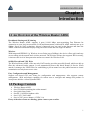
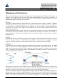
1.1 An Overview of the Wireless Router ADSL
Broadband Sharing and IP sharing
The Wireless Router ADSL supports 4 ports 10/100 Mbps auto-negotiating Fast Ethernet for
connection to your local area network (LAN) and downstream (with built-in ADSL modem) rate up to
8Mbps. Power by NAT technology, dozens of network users can surf on the Internet and share the
ADSL connection simultaneously by using one ISP account and one single IP address.
Wireless
With integrated IEEE802.11g Wireless Access Point (up to 54Mbps), the device offers quick and easy
access among wired network and wireless network. The Wireless Router also supports WPA security,
it increases the level of data protection and access control for Wireless LAN.
SOHO Firewall and VPN IPSec
The Wireless Router ADSL offers not only NAT but also provides powerful firewall, which are able to
filter the advanced hacker pattern. It can automatically detect and block Denial of Service (DoS)
attacks. It manages the VPNs IPSec for establishing a private tunnel over the public Internet to ensure
transmission security between two sites.
Easy Configuration and Management
Support web based GUI and Telnet for configuration and management. Also supports remote
management (Web and telnet) capability for remote user to configure and manage this product. It
incorporates besides a client Dynamic DNS.
1.2 Package Contents
• Wireless Router ADSL
• One CD-ROM containing the online manual
• One Quick Start Guide
• One RJ-11 ADSL/telephone cable
• One CAT-5 LAN cable
• One AC-DC power adapter (12VDC, 1A)
If any of the above items are missing, please contact your reseller.
1
WIRELESS ROUTER ADSL
1.3 Wireless Router ADSL Features
Wireless ADSL Router provides the following features:
•
ADSL Multi-Mode Standard: Supports downstream transmission rates of up to 8Mbps and
upstream transmission rates of up to 1024Kbps. It also supports rate management that allows
ADSL subscribers to select an Internet access speed suiting their needs and budgets. It is
compliant with Multi-Mode standard (ANSI T1.413, Issue 2; G.dmt (G.992.1); G.lite (G992.2).
•
Fast Ethernet Switch: A 4-port 10/100Mbps fast Ethernet switch is supported in the LAN site
and automatic switching between MDI and MDI-X for 10Base-T and 100Base-TX ports is
supported. An Ethernet straight or cross-over cable can be used directly, this fast Ethernet
switch will detect it automatically.
•
Wireless Ethernet 802.11g: With built-in 802.11g access point for extending the
communication media to WLAN while providing the WEP and WPA for securing your
wireless networks.
•
Multi-Protocol to Establish A Connection: Supports PPPoA (RFC 2364 - PPP over ATM
Adaptation Layer 5), RFC 1483 encapsulation over ATM (bridged or routed), PPP over
Ethernet (RFC 2516), and IPoA (RFC1577) to establish a connection with the ISP. The product
also supports VC-based and LLC-based multiplexing.
•
Quick Installation Wizard: Supports a WEB GUI page to install this device quickly. With
this wizard, an end user can enter the information easily which they from the ISP, then surf the
Internet immediately.
•
Universal Plug and Play (UPnP) and UPnP NAT Traversal: This protocol is used to enable
simple and robust connectivity among stand-alone devices and PCs from many different
vendors. It makes network simple and affordable for users. UPnP architecture leverages
TCP/IP and the Web to enable seamless proximity networking in addition to control and data
transfer among networked devices.
•
Network Address Translation (NAT): Allows multi-users to access outside resource such as
Internet simultaneously with one IP address/one Internet access account. Besides, many
application layer gateway (ALG) are supported such as web browser, ICQ, FTP, Telnet, Email, News, Net2phone, Ping, NetMeeting and others.
•
Firewall: Supports SOHO firewall with NAT technology. Automatically detects and blocks
the Denial of Service (DoS) attack. The URL-blocking, packet filtering are also supported. The
hacker’s attack will be recorded associated with timestamp in the security logging area. More
firewall features will be added continually, please visit our web site to download latest
firmware.
•
Domain Name System (DNS) relay: provides an easy way to map the domain name (a
friendly name for users such as www.yahoo.com) and IP address. When a local machine sets
its DNS server with this router’s IP address, then every DNS conversion requests packet from
the PC to this router will be forwarded to the real DNS in the outside network. After the router
gets the reply, then forwards it back to the PC.
2
•
WIRELESS ROUTER ADSL
Dynamic Domain Name System (DDNS): The Dynamic DNS service allows you to alias a
dynamic IP address to a static hostname. This dynamic IP address is the WAN IP address. For
example, to use the service, you must first apply an account from this free Web server
http://www.dyndns.org/. There are more than 5 DDNS servers supported.
•
Virtual Private Network (VPN): Allows a user to make a tunnel with a remote site directly to
secure the data transmission among the connection. Users can use embedded IPSec end point
supported by this router to make a VPN tunnel.
•
PPP over Ethernet (PPPoE): Provide embedded PPPoE client function to establish a
connection. Users can get greater access speed without changing the operation concept, sharing
the same ISP account and paying for one access account. No PPPoE client software is required
for the local computer. The Always ON, Dial On Demand and auto disconnection (Idle Timer)
functions are provided too.
•
Virtual Server: Users can specify some services to be visible from outside users. The router
can detect incoming service request and forward it to the specific local computer to handle it.
For example, users can assign a PC in a LAN acting as a WEB server inside and expose it to
the outside network. Outside users can browse an inside web server directly while it is
protected by NAT. A DMZ host setting is also provided to a local computer exposed to the
outside network, Internet
•
Rich Packet Filtering: Not only filters the packet based on IP address, but also based on Port
numbers. It also provides a higher-level security control.
•
Dynamic Host Control Protocol (DHCP) client and server: In the WAN site, the DHCP
client can get an IP address from the Internet Server Provider (ISP) automatically. In the LAN
site, the DHCP server can allocate up to 253 client IP addresses and distribute them including
IP address, subnet mask as well as DNS IP address to local computers. It provides an easy way
to manage the local IP network.
•
Static and RIP1/2 Routing: Supports an easy static table or RIP1/2 routing protocol to
support routing capability.
•
SNTP: An easy way to get the network real time information from an SNTP server.
•
SNMP: SNMP is an application layer protocol that is used for managing networks (V1,V2 and
V3)
•
Web based GUI: supports web based GUI for configuration and management. It is userfriendly with an on-line help, providing necessary information and assist user timing. It also
supports remote management capability for remote users to configure and manage this product.
•
Firmware Upgradeable: the device can be upgraded to the latest firmware through the WEB
based GUI.
•
Rich management interfaces: Supports flexible management interfaces with local console
port, LAN port, and WAN port. Users can use terminal application through console port to
configure and manage the device, or Telnet, WEB GUI, and SNMP through LAN or WAN
ports to configure and manage a device.
3
WIRELESS ROUTER ADSL
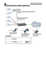
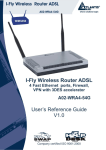
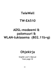
1.4 Wireless Router ADSL Application
4
WIRELESS ROUTER ADSL
Chapter 2
Using Wireless Router ADSL
2.1 Cautions for using the Wireless Router ADSL
Do not place the ADSL Wireless Router under high humidity and high temperature.
Do not use the same power source for ADSL Wireless Router with other equipment.
Do not open or repair the case yourself. If the ADSL Wireless Router is too hot, turn
off the power immediately and have a qualified serviceman repair it.
Place the ADSL Wireless Router on a stable surface.
Only use the power adapter that comes with the package.
Do NOT upgrade firmware on any Atlantis Land product over a wireless connection.
Failure of the device may result. Use only hard-wired network connections.
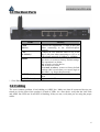
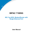
2.2 The Front LEDs
LED
POWER
SYS
WLAN
LAN
ADSL
5
Meaning
Lit when power ON
Blinking when system is ready
Lit green when the wireless connection is established. Flashes
when sending/receiving data.
Lit when connected to Ethernet device
Green for 100Mbps; Orange for 10Mbps
Blinking when data transmit/received
Lit when successfully connected to an ADSL DSLAM
WIRELESS ROUTER ADSL
2.3 The Rear Ports
PORT
Meaning
Connect the supplied RJ-11 cable to this port
when connecting to the ADSL/telephone
network.
Connect an UTP Ethernet cable to one of the
LAN
four LAN ports when connecting to a PC or an
(4 *RJ-45)*
office/home network of 10Mbps or 100Mbps.
After the device has turned on, press it to reset
RESET
the device or restore to factory default settings.
The operation is as below:
0-3 seconds: reset the device
3-6 seconds: no action
6 seconds or above: restore to factory default
settings (this is used when you can not login to
the router, e.g. forgot the password)
Connect the supplied power adapter to this
POWER (Jack)
jack.
A Power ON/OFF switch
POWER Switch
* 1 Fast Ethernet port on A02-RA210-W54.
LINE
(RJ-11)
2.4 Cabling
The most common problem is bad cabling or ADSL line. Make sure that all connected devices are
turned on. On the front of the product is a bank of LEDs. As a first check, verify that the LAN Link
and ADSL line LEDs are lit and SYS is blanking. If they are not, verify that you are using the proper
cables.
6
WIRELESS ROUTER ADSL
Chapter 3
Configuration
The ADSL Wireless Router can be configured with your Web browser. The web browser is included
as a standard application in the following operation systems, UNIX, Linux, Mac OS, Windows
95/98/NT/2000/Me, and etc. The product provides a very easy and user-friendly interface for
configuration.
3.1 Before Configuration
This section describes the configuration required by LAN-attached PCs that communicate with the
ADSL Wireless Router, either to configure the device or for network access. These PCs must have an
Ethernet interface (or wireless adapter) installed properly, be connected to the ADSL Wireless Router
either directly or through an external repeater hub, and have TCP/IP installed and configured to obtain
an IP address through a DHCP server or a fixed IP address that must be in the same subnet of the
ADSL Firewall Router. The default IP address of the ADSL Wireless Router is 192.168.1.254 and
subnet mask is 255.255.255.0. The best and easy way is to configure the PC to get an IP address from
the ADSL Wireless Router. Also make sure you have UNINSTALLED any kind of software firewall
that can cause problems while accessing the 192.168.1.254 IP address of the router.
Please follow the steps below for PC’s network environment installation. First of all, please check
your PC’s network components. The TCP/IP protocol stack and Ethernet network adapter must be
installed. If not, please refer to MS Windows related manuals.
Any TCP/IP capable workstation can be used to communicate with or through
the ADSL Wireless Router. To configure other types of workstations, please
consult the manufacturer’s documentation.
3.2 Connecting the Wireless Router ADSL
•
•
•
•
7
Connect the Router to a LAN (Local Area Network) and the ADSL/telephone network.
Power on the device
Make sure the PWR (SYS LED is blinking) is lit steady & LAN/WLAN LED is lit.
Before taking the next step, make sure you have uninstalled any software firewall.
WIRELESS ROUTER ADSL
3.3 Configuring PC in Windows
For Windows 95/98/ME
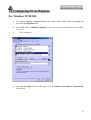
1.
Go to Start / Settings / Control Panel. In the Control Panel, double-click on Network and
choose the Configuration tab.
2.
Select TCP / IP -> NE2000 Compatible, or the name of any Network Interface Card (NIC)
in your PC.
3.
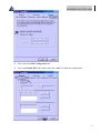
4.
Click Properties.
Select the IP Address tab. In this page, click the Obtain an IP address automatically
radio button.
8
WIRELESS ROUTER ADSL
5.
Then select the DNS Configuration tab.
6.
Select the Disable DNS radio button and click “OK” to finish the configuration.
9
WIRELESS ROUTER ADSL
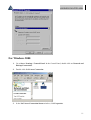
For Windows NT4.0
1.
Go to Start / Settings / Control Panel. In the Control Panel, double-click on Network and
choose the Protocols tab.
2.
Select TCP/IP Protocol and click Properties.
3.
Select the Obtain an IP address from a DHCP server radio button and click “OK”.
10
WIRELESS ROUTER ADSL
For Windows 2000
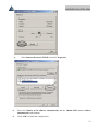
1.
Go to Start / Settings / Control Panel. In the Control Panel, double-click on Network and
Dial-up Connections.
2.
Double-click LAN Area Connection.
3.
In the LAN Area Connection Status window, click Properties.
11
WIRELESS ROUTER ADSL
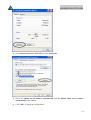
4.
Select Internet Protocol (TCP/IP) and click Properties.
5.
Select the Obtain an IP address automatically and the Obtain DNS server address
automatically radio buttons.
6.
Click “OK” to finish the configuration.
12
WIRELESS ROUTER ADSL
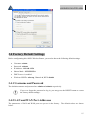
For Windows XP
1. Go to Start / Control Panel (in Classic View). In the Control Panel, double-click on
Network Connections.
2. Double-click Local Area Connection
3. In the LAN Area Connection Status window, click Properties.
13
WIRELESS ROUTER ADSL
4. Select Internet Protocol (TCP/IP) and click Properties.
5. Select the Obtain an IP address automatically and the Obtain DNS server address
automatically radio buttons
6. Click “OK” to finish the configuration.
14
WIRELESS ROUTER ADSL
3.4 Factory Default Settings
Before configurating this ADSL Wireless Router, you need to know the following default settings.
•
Username: admin
•
Password : atlantis
•
IP Address : 192.168.1.254
•
Subnet Mask : 255.255.255.0
•
DHCP server is enabled.
•
Wireless: SSSID= wlan-ap, Channel=6, WEP=disable
3.4.1 Username and Password
The default username and password are admin and atlantis respectively.
If you ever forget the password to log in, you may press the RESET button to restore
the factory default settings..
3.4.2 LAN and WAN Port Addresses
The parameters of LAN and WAN ports are pre-set in the factory. The default values are shown
below.
15
WIRELESS ROUTER ADSL
WAN Port
LAN Port
IP address
192.168.1.254
Subnet Mask
255.255.255.0
DHCP server function
Enabled
N/A
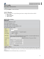
3.5 Information from the ISP
Before configuring this device, you have to check with your ISP (Internet Service Provider) what kind
of service is provided such as PPPoE, PPPoA, RFC1483, IpoA.
Gather the information as illustrated in the following table and keep it for reference.
PPPoE
PPPoA
VPI/VCI, VC-based/LLC-based multiplexing, Username,
Password, Service Name, and Domain Name System (DNS) IP
address (it can be automatically assigned from ISP or be set
fixed).
VPI/VCI, VC-based/LLC-based multiplexing, Username,
Password, and Domain Name System (DNS) IP address (it
can be automatically assigned from ISP or be set fixed).
RFC1483 Bridged
RFC1483 Routed
IPoA
VPI/VCI, VC-based/LLC-based multiplexing and configure
this product into BRIDGE Mode.
VPI/VCI, VC-based/LLC-based multiplexing, IP address,
Subnet mask, Gateway address, and Domain Name System
(DNS) IP address (it is fixed IP address).
VPI/VCI, IP address, Subnet mask, Gateway address, and
Domain Name System (DNS) IP address (it is fixed IP
address).
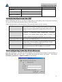
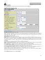
3.6 Configuring with the Web Browser
Open the web browser, enter the local port IP address of this ADSL Wireless Router, which defaults at
http://192.168.1.254, and click “Go”, a username and password window will appear. The default
username & password are admin & atlantis, in respectively
16
WIRELESS ROUTER ADSL
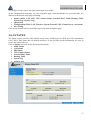
You will get a status report web page when login successfully.
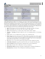
At the configuration homepage, the left navigation page where bookmarks are provided links you
directly to the desired setup page, including:
•
Status (ADSL, LAN, PPP, VPN connect Status, Learned MAC Table, Routing Table,
System Log, Security Log)
• Quick Start
• Configuration (WAN, LAN, Wireless, System, Firewall, VPN, Virtual Server, Advanced)
• Save Config
Click on the desired item to expand the page in the main navigation page.
3.6.1 STATUS
The Status section provides and contains many items including device H/W and S/W information,
LAN, WAN, Port status and all defined interfaces. It also provides useful information for users to
review the status of device.
Click on Status will open all the following subsections:
• ADSL Status
• LAN Status
• PPP Status
• VPN Connect Status
• Learned MAC Table
• Routing Table
• System Log
• Security Log
17
WIRELESS ROUTER ADSL
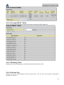
3.6.1.1 ADSL Status
the status of your ADSL connection. It will refresh every two seconds.
18
WIRELESS ROUTER ADSL
3.6.1.2 LAN Status
Displays the status of your Local Area Network (LAN) connection.
Display the status of TCP. This screen will automatically refresh every two seconds.
3.6.1.3 PPP Status
Displays the status of your PPP connection. It will refresh every ten seconds.
3.6.1.4 VPN Connect Status
When you click the VPN Connect Status, it gives you a quick view to know the ADSL Router’s
current status. The status of VPN connection will be shown.
19
WIRELESS ROUTER ADSL
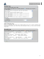
3.6.1.5 Learned MAC Table
Aging Timeout: Enter the time period for the router to memorize MAC addresses.
3.6.1.5 Routing Table
Display the current routing paths of A02-RA240-W54/A02-RA210-W54.
3.6.1.6 System Log
Display the system logs cumulated till the present time. You can trace the historical information
through this function.
20
WIRELESS ROUTER ADSL
.
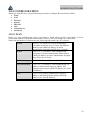
3.8.1.7 Security Log
Display the information of security logs. If hacker attacks your sever, he will be isolated by the
firewall function and the router will record related information. Hence, you know where the hacker
comes from.
21
WIRELESS ROUTER ADSL
3.8.2 CONFIGURATION
When you click this item, you get following sub-items to configure Wireless Router ADSL:
• WAN
• LAN
• Wireless
• System
• Firewall
• VPN
• Virtual Server
• Advanced
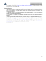
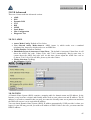
3.8.2.1 WAN
Before you start installing this device, you have to check with your ISP what kind of service
(connection method) is provided such as PPPoE, PPPoA, RFC1483 bridged or routed, IPoA.
Gather the information as illustrated in the following table and keep it for reference.
VPI/VCI, VC-based/LLC-based multiplexing,
PPPoE
Username, Password, Service Name, and Domain
Name System (DNS) IP address (it can be
automatically assigned from ISP or be set fixed).
PPPoA
VPI/VCI, VC-based/LLC-based multiplexing,
Username, Password, and Domain Name System
(DNS) IP address (it can be automatically assigned
from ISP or be set fixed).
RFC1483 Bridged
VPI/VCI, VC-based/LLC-based multiplexing
RFC1483 Routed
VPI/VCI, VC-based/LLC-based multiplexing, IP
address, Subnet mask, Gateway address, and
Domain Name System (DNS) IP address (it is fixed
IP address).
IPoA
VPI/VCI, IP address, Subnet mask, Gateway
address, and Domain Name System (DNS) IP
address (it is fixed IP address).
22
WIRELESS ROUTER ADSL
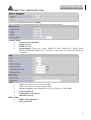
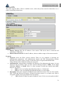
PPPoE(RFC 2516) / PPPoA(RFC 2364)
Pvc0 is set as default and then press submit.
The screens below contain settings for the WAN interface toward Internet.
Virtual Circuit
•
Virtual Circuit=Enabled
•
Bridge=disabled
•
IGMP=disabled
•
Encapsulation= There are 5 ways :PPPoE VC-Mux, PPPoE LLC, PPPoE None,
PPPoA VCMux, and PPPoA LLC. You have to check with your ISP about which way
is adopted.
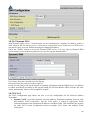
ATM
•
•
•
•
•
•
DHCP Client
•
•
VPI=8 (You have to check with your ISP)
VCI=35 (You have to check with your ISP)
Service Category= The Quality of Service for ATM layer. Select UBR.
Peak Cell Rate=0
Sustainable CeLL Rate=0
Max Burst Size=0
DHCP Client=Disabled
Host Name=idle
23
WIRELESS ROUTER ADSL
MAC Spoofing
•
MAC Spoofing, The MAC Spoofing is for solving the scenario when the ISP only
recognizing the specified MAC address.
•
MAC Address= 00:00:00:00:00:00
Static IP Settings
•
Static IP Address=0.0.0.0
•
Subnet Mask=0.0.0.0
•
Gateway=0.0.0.0
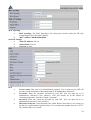
PPP
•
•
•
•
Service name: This item is for identification purposes. If it is required, your ISP will
provide you the information. Maximum input is 20 alphanumeric characters.
Username: Enter the username provided by your ISP. You can input up to 63
alphanumeric characters (case sensitive). This will usually be in the format of
“username@ispname” instead of simply “username”.
Password: Enter the password provided by your ISP. You can input up to 63
alphanumeric characters (case sensitive).
Disconnect Timeout: Auto-disconnect the ADSL Router when there is no activity on
the line for a predetermined period of time. You can input any number from 0 to 32767.
The default value is 0 seconds.
24
WIRELESS ROUTER ADSL
MRU: Maximum Receive Unit indicates the peer of PPP connection the maximum size
of the PPP information field this device can be received. The default value is 1492 and
is used in the beginning of the PPP negotiation. In the normal negotiation, the peer will
accept this MRU and will not send packet with information field larger than this value.
•
MTU: Maximum Transmission Unit indicates the network stack of any packet is larger
than this value will be fragmented before the transmission. During the PPP negotiation,
the peer of the PPP connection will indicate its MRU and will be accepted. The actual
MTU of the PPP connection will be set to the smaller one of MTU and the peer’s MRU.
The default value is 1492.
•
MSS: Maximum Segment Size is the largest size of data that TCP will send in a single
IP packet. When a connection is established between LAN client and a host in the
WAN side, the LAN client and the WAN host will indicate their MSS during the TCP
connection handshake. The default value is 1492.
•
Authentication: Default is Chap (Auto). Your ISP will advise you whether to use Chap
or Pap
•
Automatic Reconnect: Check to enable this device to automatically re-establish the
PPPoE session when disconnected by ISP.
Press Submit and then click on Save Config.
•
Press again Submit. to reboot the Router.
25
WIRELESS ROUTER ADSL
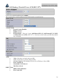
RFC 1483 Routing / Classical IP over ATM (RFC 1577)
Pvc0 is set as default and then press submit.
The screens below contain settings for the WAN interface toward Internet.
Virtual Circuit
•
Virtual Circuit=Enabled
•
Bridge=disabled
•
IGMP=disabled
•
Encapsulation= There are 3 ways :1483 Routed IP LLC, 1483 Routed IP VC-MUX
or Classical IP over ATM ( RFC 1577). You have to check with your ISP about which
way is adopted.
ATM
•
•
•
•
•
•
DHCP Client
•
•
VPI=8 (You have to check with your ISP)
VCI=35 (You have to check with your ISP)
Service Category= The Quality of Service for ATM layer. Select UBR.
Peak Cell Rate=0
Sustainable CeLL Rate=0
Max Burst Size=0
DHCP Client=Disabled
Host Name=idle
26
WIRELESS ROUTER ADSL
MAC Spoofing
•
MAC Spoofing, The MAC Spoofing is for solving the scenario when the ISP only
recognizing the specified MAC address.
•
MAC Address= 00:00:00:00:00:00
Static IP Settings
•
Static IP Address= Enter the information provided by your ISP.
•
Subnet Mask= Enter the information provided by your ISP.
•
Gateway= Enter the information provided by your ISP.
Press Submit and then click on Save Config.
Press again Submit. to reboot the Router.
27
WIRELESS ROUTER ADSL
3.8.2.2 LAN
This screen contains settings for LAN interface attached to the LAN port.
3.8.2.2.1 LAN Configuration
IP Address: Default at 192.168.1.254.
This is the device IP address in LAN site. If you plan to change it to another IP address to a different
ange of IP subnet. Please make sure your PC is also located at the same IP subnet. Otherwise, you may
not be able to access the router.
Subnet Mask: Default at 255.255.255.0.
DHCP Server: Check DHCP Server to enable the router to distribute IP Addresses, subnet mask and
NS setting to computers. Hence, the following fields will be activated. If you do not check this
selection, emember to specify a static IP address, subnet Mask, and DNS setting for each of your local
computers.
Be careful not to assign the same IP address to different computers.
DHCP Address pool selection: Auto or User Defined. If select the AUTO, router will assign an IP
address back to PC’s IP request. If User Defined, please specify the IP pool range.
User Defined Start Address: Enter the start address of this local IP network address pool. The pool is
a piece of continuous IP address segment. The default value is 192.168.1.100.
User Defined End Address: Enter the last address of this local IP network address pool that you
want the DHCP server to assign IP addresses to. The default value is 192.168.1.199.
With this case, the DHCP pool is from 192.168.1.100 to 192.168.1.199. Therefore, the local computer
will get an IP address located at this range randomly.
Press Submit and then click on Save Config.
28
WIRELESS ROUTER ADSL
Press again Submit. to reboot the Router.
3.8.2.3 Wireless
When you click this item, you get following sub-items to configure Wireless Router ADSL:
• Basic setting
• Advanced setting
• Wlan security
3.8.2.3.1 Base Settings
ESSID: Enter the unique ID given to the Access Point (AP), which is already built-in to the router’s
wireless interface. To connect to this device, your wireless clients must have the same ESSID as the
device.
Channel ID: Select the ID channel that you would like to use.
29
WIRELESS ROUTER ADSL
Security:
WEP Encryption: To prevent unauthorized wireless stations from accessing data transmitted
over the network, the router offers highly secure data encryption, known as WEP. If you
require high security for transmissions, there are two alternatives to select from: WEP 64 and
WEP 128. WEP 128 will offer increased security over WEP 64.
Passphrase: This is used to generate WEP keys automatically based upon the input string and
a pre-defined algorithm in WEP64 or WEP128. You can input the same string in both the AP
and Client card settings to generate the same WEP keys. Please note that you do not have to
enter Key (0-3) as below when the Passphrase is enabled.
Default Used WEP Key: Select the encryption key ID, please refer to Key (0-3) below.
Key (0-3): Enter the key to encrypt wireless data. To allow encrypted data transmission, the
WEP Encryption Key values on all wireless stations must be the same as the router.
There are four keys for your selection. The input format is in HEX [0,1,2,3,4,5,6,7,8,9,A,B,C,D,E,F]
style, 5 and 13 HEX codes are required for WEP64 and WEP128 respectively.
Secret AP:
• Enable: Any client that using the “any” setting cannot discover the Access Point (AP) in
question.
• Disable: Any client that using the “any” setting can discover the Access Point (AP) in
question.
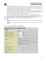
3.8.2.3.2 Advanced Wireless Configuration
30
WIRELESS ROUTER ADSL
3.8.2.3.3 Wi-FI Protected Access(WPA)
WPA-PSK:
• Data Encryption: TKIP (Temporal Key Integrity Protocol) utilizes a stronger encryption
method and incorporates Message Integrity Code (MIC) to provide protection against hackers.
• WPA Pre-Shared Key: The key for network authentication. The input format is in character
style and key size should be in the range between 8 and 63 characters.
• WPA Pre-Shared Key: The period of renewal time for changing the security key
automatically between wireless client and Access Point (AP).
RADIUS
•
•
•
RADIUS Server Address: IP address of Radius
RADIUS Server port: port
RADIUS Shared Secret: shared key
31
WIRELESS ROUTER ADSL
3.8.2.4 SYSTEM
There are five items under the System section:
• Password
• TimeZone
• Upgrade
• Factory Settings
• Restart
3.8.2.4.1 Password
Every time you change your password, please record the password and keep it at a safe place.
If you ever forget the password to log in, you may press the RESET button up to 10
seconds to restore the factory default settings. (user="admin", password="Atlantis")
Please note that the maximum input for password is 16 alphanumeric characters long. Since it is case
sensitive, be sure that you remember whether a letter is in upper or lower case and make sure that your
Caps Lock is off.
3.8.2.4.2 Time Zone
The Wireless Router ADSL does not have a real time clock on board; instead, it uses the simple
network time protocol (SNTP) to get the current time from the SNTP server in outside network.
Please choose your local time zone and click Submit. You will get the correct time information after
you really establish a connection to Internet. The current time of selected time zone will be shown in
the Status (System window).
Automatically adjust clock for daylight saving changes: It is optional for different time zone area.
SNTP Server IP Address: Specify the IP address if you want to use your familiar SNTP server.
3.8.2.4.3 Upgrade
When you click ConfigurationFirmware Upgrade, it allows you to input the location of firmware
stored on your PC and click the Upgrade button to upgrade to the new firmware.
32
WIRELESS ROUTER ADSL
Do NOT upgrade firmware on any Atlantis Land product over a wireless
connection.
Failure of the device may result. Use only hard-wired network connections.
Click Image Download.
Press the Sfoglia button to specify the path of the firmware file. Then, click Upload to start upgrading.
When the procedure is completed, Router will reset automatically to make the new firmware work.
3.8.2.4.4 Factory Settings
If for any reason, you have to reset this router back to factory default settings, be careful that the
current settings will be lost and the settings are reset back to its default value. The factory default
values is detailed in the section 3.4 ‘‘Factory Default Settings’’.
3.8.2.4.5 Restart
In case the router stops responding correctly or in some other way stops functioning, you can perform
the reboot. Your setting won’t be changed. Performing the reboot, click on the Restart button.
33
WIRELESS ROUTER ADSL
3.8.2.5 Firewall
Your router includes a full DoS firewall for controlling Internet access from your LAN, as well as
helping to prevent attacks from hackers. In addition to this, when using NAT (Network Address
Translation. Please see the WAN configuration section for more details on NAT) the router acts as a
“natural” Internet firewall, as all PCs on your LAN will use private IP addresses that cannot be directly
accessed from the Internet.
Firewall: Prevents access from outside your network. The router provides three levels of security
support:
NAT natural firewall: This masks LAN users’ IP addresses which are invisible to outside users on
the Internet, making it much more difficult for a hacker to target a machine on your network.
This natural firewall is on when NAT function is enabled.
Firewall Security and Policy (General Settings): Inbound direction of Packet Filter rules to prevent
unauthorized computers or applications accessing your local network from the Internet.
Intrusion Detection: Enable Intrusion Detection to detect, prevent and log malicious attacks.
Access Control: Prevents access from PCs on your local network:
Firewall Security and Policy (General Settings): Outbound direction of Packet Filter rules to
prevent unauthorized computers or applications accessing the Internet.
MAC Filter rules: To prevent unauthorized computers accessing the Internet.
URL Filter: To block PCs on your local network from unwanted websites.
You can find six items under the Firewall section: General Settings, Packet Filter, Intrusion Detection,
MAC Address Filter, URL Filter and Firewall Log.
You can choose not to enable Firewall, to add all filter rules by yourself, or enable the Firewall using
preset filter rules and modify the port filter rules as required.
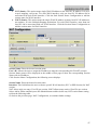
3.8.2.5.1 Packet Filering
User can decide to enable this firewall function including Packet Filter, Block Hacker Attack, and
Block WAN request features for better security control or not. But be noted, it wastes network
processor computation power. The performance will be lower about 10% to 15%. More firewall
features will be added continually, please visit our web site to download latest firmware.
Packet filtering function enables you to configure your router to check specified internal/external user
(IP address) from Internet access, or you can disable specific service request (Port number) to /from
Internet. This configuration program allows you to set up different filter rules up to 10 for different
users based on their IP addresses or their network Port number. The relationship among all filters is
“or” operation, which means the device checks these different filter rules one by one, stating from the
first rule.
As long as one of the rules is satisfied, the specified action will be taken. remote server using the port
number.
34
WIRELESS ROUTER ADSL
Packet filtering function enables you to configure your router to check specified internal/external user
(IP address) from Internet access, or you can disable specific service request (Port number) to /from
Internet. This configuration program allows you to set up different filter rules up to 10 for different
users based on their IP addresses or their network Port number. The relationship among all filters is
“or” operation, which means the device checks these different filter rules one by one, stating from the
first rule.As long as one of the rules is satisfied, the specified action will be taken.
•
Add: Click this button to add a new packet filter rule. After click, next figure will appear.
•
Edit: Check the Rule No. you want to edit. Then, click the “Edit” button.
•
Delete: Check the Rule No. you want to delete. Then, click the “Delete” button.
•
Outgoing / Incoming: Determine whether the rule is for outgoing packets or for incoming
packets.
•
Active: Choose “Yes” to enable the rule, or choose “No” to disable the rule.
•
Packet Type: Specify the packet type (TCP, UDP, ICMP or any) that the rule will be applied
to.Select TCP if you want to scope for the connection-based application service on the remote
server using the port number. Or select UDP if you want to scope for the connectionless
application service on the remote server using the port number.
•
Log: Choose “Yes” if you want to generate logs when the filer rule is applied to a packet.
•
Action When Matched: If any packet matches this filter rule, Forward or Drop this packet.
•
Source IP Address: Enter the incoming or outgoing packet’s source IP address(es).
•
Source Port: Check the TCP or UDP packet’s source port number(s).
•
Destination IP Address: Enter the incoming or outgoing packet’s destination IP address(es).
•
Destination Port: Check the TCP or UDP packet’s destination port number(s).
35
WIRELESS ROUTER ADSL
3.8.2.5.2 Bridge Filtering
MAC filtering function enables you to configure your ADSL Firewall Router to block internal user
(MAC address) from Internet access.
~ Enable / Disable: Check Enable / Disable radio button to active / disable, in respectively, the
MAC address filter function. If you check Enable, remember to choose either Allowed or Blocked
the MAC Address listed in the table, as shown above. If you select Blocked, the packet with the MAC
address in the table will be dropped and others will be forwarded. If you select Allowed, the packet
with the MAC address in the table will be forwarded and others will be dropped. Then select Apply
button to save the setting.
3.8.2.5.3 Intrusion Detection
The router’s Intrusion Detection System (IDS) is used to detect hacker attacks and intrusion attempts
from the Internet. If the IDS function of the firewall is enabled, inbound packets are filtered and
blocked depending on whether they are detected as possible hacker attacks, intrusion attempts or other
connections that the router determines to be suspicious.
Hacker attack types recognized by the IDS:
•
IP Spoofing
•
Ping of Death (Length > 65535)
•
Land Attack (Same source / destination IP address)
•
IP with zero length
•
Sync flooding
•
Smurf Attack (ICMP Echo with x.x.x.0 or x.x.x.255)
•
Snork Attack
•
UDP port loop-back
•
TCP NULL scan
36
WIRELESS ROUTER ADSL
3.8.2.5.4 Block Wan Request
The “Block WAN Request” is a stand-alone function and not relate to whether security enable or
disable. Mostly it is for preventing any scan tools from WAN site by hacker.
3.8.2.5.5 URL Blocking
URL filter rules allow you to prevent users on your network from accessing particular websites by
their URL. There are no predefined URL filter rules; you can add filter rules to meet your
requirements.
Keywords Filtering:
Allows blocking by specific keywords within a particular URL rather than having to specify a
complete URL (e.g. to block any image called “advertisement.gif”).
When enabled, your specified keywords list will be checked to see if any keywords are present
in URLs accessed to determine if the connection attempt should be blocked.
Please note that the URL filter blocks web browser (HTTP) connection attempts using port 80
only.
37
WIRELESS ROUTER ADSL
For example, if the URL is http://www.atlantis-land.com/start.html, it will be dropped as the
keyword “start” occurs in the URL.
Domains Filtering:
This function checks the domain name in URLs accessed against your list of domains to block or
allow. If it is matched, the URL request will be sent (Trusted) or dropped (Forbidden). The
checking procedure is:
1. Check the domain in the URL to determine if it is in the trusted list. If yes, the connection
attempt is sent to the remote web server.
2. If not, check if it is listed in the forbidden list, and if present then the connection attempt is
dropped..
3. If the packet does not match either of the above two items, it is sent to the remote web server.
4. Please be note that the domain only should be specified, not the full URL. For example to
block traffic to www.sex.com, enter “sex” or “sex.com” instead of “www.sex.com”. In the
example below, the URL request for www.helloworld.com.tw will be sent to the remote web
server because it is listed in the trusted list, whilst the URL request for www.sex or
www.sex.com will be dropped, because helloworld.com is in
the forbidden list.
38
WIRELESS ROUTER ADSL
3.8.2.6 VPN
The router supports IPSec VPN to establish secure, end-to-end private network connections over a
public networking infrastructure.
Click on Submit.
Remote:
• Remote Gateway IP: The IP address of the remote VPN device that is connected and
establishes a VPN tunnel.
• Remote Subnet/Network: Set the IP address, subnet or address range of the remote network.
Proposal:
• Proposal: Select the IPSec security method. There are two methods of checking the
authentication information, AH (authentication header) and ESP (Encapsulating Security
Payload). Use ESP for greater security so that data will be encrypted and authenticated.
Using AH data will be authenticated but not encrypted.
• Authentication: Authentication establishes the integrity of the datagram and ensures it is not
tampered with in transmit. There are three options, Message Digest 5 (MD5), Secure Hash
Algorithm (SHA-1) or NONE. SHA-1 is more resistant to brute-force attacks than MD5,
however it is slower.
•
MD5: A one-way hashing algorithm that produces a 128-bit hash.
•
SHA-1: A one-way hashing algorithm that produces a 160-bit hash.
• Encryption: Select the encryption method from the pull-down menu. There are four options,
DES, 3DES and Without Encryption. Without Encryption means it is a tunnel only with no
encryption. 3DES is more powerful but increase latency.
•
DES: Stands for Data Encryption Standard, it uses 56 bits as an encryption method.
39
WIRELESS ROUTER ADSL
•
3DES: Stands for Triple Data Encryption Standard, it uses 168 (56*3) bits as an
encryption method.
Perfect Forward Secrecy: Choose whether to enable PFS using Diffie-Hellman publickey
cryptography to change encryption keys during the second phase of VPN negotiation. This function
will provide better security, but extends the VPN negotiation time. Diffie- Hellman is a public-key
cryptography protocol that allows two parties to establish a shared secret over an unsecured
communication channel (i.e. over the Internet). There are three modes, MODP 768-bit, MODP 1024bit and MODP 1536-bit. MODP stands for Modular Exponentiation Groups.
Pre-shared Key: This is for the Internet Key Exchange (IKE) protocol, a string from 4 to 128
characters. Both sides should use the same key. IKE is used to establish a shared security policy and
authenticated keys for services (such as IPSec) that require a key.
Before any IPSec traffic can be passed, each router must be able to verify the identity of its peer. This
can be done by manually entering the pre-shared key into both sides (router or hosts).
SA Lifetime: Specify the number of minutes that a Security Association (SA) will stay active before
new encryption and authentication key will be exchanged. There are two kinds of SAs, IKE and IPSec.
IKE negotiates and establishes SA on behalf of IPSec, an IKE SA is used by IKE.
Phase 1 (IKE): To issue an initial connection request for a new VPN tunnel. The range can be from 5
to 15,000 minutes, and the default is 240 minutes.
Phase 2 (IPSec): To negotiate and establish secure authentication. The range can be from 5 to 15,000
minutes, and the default is 60 minutes.
A short SA time increases security by forcing the two parties to update the keys. However, every time
the VPN tunnel re-negotiates, access through the tunnel will be temporarily disconnected.
40
WIRELESS ROUTER ADSL
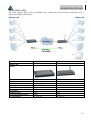
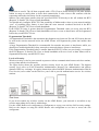
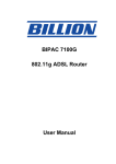
3.8.2.6.1 IPsec VPN
The router supports IPSec VPN to establish secure, end-to-end private network connections over a
public networking infrastructure.
Model Code
Picture
IP
NAT
LAN IP
Subnet Mask
VPN IPSec
Encryption
Authentication
Perfect Forward Secrety
Pre Shared Key
Remote LAN
A02-RA3+
Office LAN
A02-RA240-54G /A02-RA210-W54
69.121.1.31
Yes
192.168.1.X
255.255.255.0
ESP
DES
MD5
None
123456789
69.121.1.32
Yes
192.168.2.X
255.255.255.0
ESP
DES
MD5
None
123456789
41
WIRELESS ROUTER ADSL
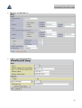
•
Remote LAN(A02-RA3+):
•
Office LAN(A02-RA240-W54):
42
WIRELESS ROUTER ADSL
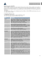
3.8.2.7 Virtual Server
When you click Virtual Server, you get the following figure.
Being a natural Internet firewall, this network router protects your network from being accessed by
outside users. When it needs to allow outside users to access internal servers, e.g. Web server, FTP
server, E-mail server or News server, this modem can act as a virtual server. You can set up a local
server with specific a port number that stands for the service, e.g. Web (80), FTP (21), Telnet (23),
SMTP (25), POP3 (110), When an incoming access request to the router for a specified port is
received, it will be forwarded to the corresponding internal server.
For example, if you set the Service Port number 80 (Web) to be mapped to the IP Address
192.168.1.2, then all the http requests from outside users will be forwarded to the local server with IP
address of 192.168.1.2. If the port is not listed as a predefined application, you need to add it
manually.
If you have disabled the NAT option in the WAN-ISP section, this Virtual Server
function will hence be invalid.
If the DHCP server option is enabled, you have to be very careful in assigning the IP
addresses of the virtual servers in order to avoid conflicts. The easy way is that the
IP address assigned to each virtual server should not fall into the range of IP
addresses that are to be issued by the DHCP server. You can configure the virtual
server IP address manually, but it is still in the same subnet with the router.
43
Application
ICQ 98, 99a
NetMeeting 2.1 a 3.01
VDO Live
MIRC
Cu-SeeMe
PC AnyWhere
Edonkey
MSN Messanger
OutBound
N/A
N/A
N/A
N/A
7648 TCP &UDP, 24032 UDP
5632 UDP, 22 UDP, 5631 TCP,
65301 TCP
N/A
N/A
Services
File Transfer Protocol (FTP) Data
FTP Commands
Telnet
Simple Mail Transfer Protocol (SMTP) Email
Domain Name Server (DNS)
Trivial File Transfer Protocol (TFTP)
finger
World Wide Web (HTTP)
POP3 Email
SUN Remote Procedure Call (RPC)
Network News Transfer Protocol (NNTP)
Network Time Protocol (NTP)
News
Simple Management Network Protocol (SNMP)
SNMP (traps)
Border Gateway Protocol (BGP)
Secure HTTP (HTTPS)
rlogin
rexec
talk
ntalk
Open Windows
Network File System (NFS)
X11
Routing Information Protocol (RIP)
Layer 2 Tunnelling Protocol (L2TP)
WIRELESS ROUTER ADSL
Inbound
N/A
1503 TCP, 1720 TCP
N/A
N/A
7648 TCP &UDP, 24032 UDP
5632 UDP, 22 UDP, 5631 TCP,
65301 TCP
4660-4662 TCP , 4665 UDP
TCP da 6891-6900
TCP 1863
TCP 6901
UDP 1863, 6901 e 5190
Port Number / Protocol
20/tcp
21/tcp
23/tcp
25/tcp
53/tcp and 53/udp
69/udp
79/tcp
80/tcp
110/tcp
111/udp
119/tcp
123/tcp and 123/udp
144/tcp
161/udp
162/udp
179/tcp
443/tcp
513/tcp
514/tcp
517/tcp and 517/udp
518/tcp and 518/udp
2000/tcp and 2000/udp
2049/tcp
6000/tcp and 6000/udp
520/udp
1701/udp
44
WIRELESS ROUTER ADSL
3.8.2.8 Advanced
There are 9 items under the Advanced section:
• ADSL
• DNS
• Dynamic DNS
• NAT
• RIP
• SNMP
• Static Route
• Misc Configuration
• Diagnostic Test
3.8.2.8.1 ADSL
• Annex Mode Config: Default at User Select
• User Selected Annex Mode:AnnexA. ADSL Annex A, which works over a standard
telephone line. Annex B, which works over an ISDN line.
• Trellis (Enable): Default at Enabled.
• Handshake Protocol (Autosense G.dmt First): The default is Autosense G.dmt firste; it will
detect the ADSL line code, G.dmt, G.lite, and T1.413 automatically. But in some area, it
cannot detect the ADSL line code well. At this time, please adjust the ADSL line code to
G.dmt or T1.413 first. If it still fails, please try the other values.
• Wiring Selection (Tip/Ring)
• Bit Swapping (Disable)
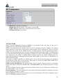
3.8.2.8.2 DNS
A Domain Name System (DNS) contains a mapping table for domain name and IP address. In the
Internet, every host has a unique and friendly name such as www.yahoo.com and IP address. The IP
address is so hard to remember that you may just enter the friendly name www.yahoo.com and then
the DNS will convert it to its equivalent IP address.
You can obtain Domain Name System (DNS) IP address automatically if ISP provides it when you
logon. Or your ISP may provide you with an IP address of DNS. If this is the case, you must enter the
DNS IP address.
45
WIRELESS ROUTER ADSL
3.8.2.8.3 Dynamic DNS
With Dynamic DNS service, a domain name can be translated into a dynamic IP address, which is
often issued by ISP for dial-up service. A local server, such as Web server, Email server or FTP server,
can then be easily accessed without knowing the changing IP address.
Check the “Enable” button to access the Dynamic DNS service. You may sign up Dynamic DNS
service at http://www.dyndns.org and there you can also register domain names.
Host: Enter one domain name you have registered.
User Name: Enter the username used for sign-up.
Password: Enter the password used for sign-up.
Period: Set the time period for the Router to exchange information with the DDNS server. In addition
to update periodically according to this period setting, the Wireless Router ADSL will take the same
action automatically whenever the assigned IP changes
3.8.2.8.4 NAT
The NAT Configuration page allows the user to set the configuration for the Network Address
Translation.
• Dynamic NAPT: It provides dynamic Network Address Translation capability between LAN
and multiple WAN connections, and the LAN traffic is routed to appropriate WAN
connections based-on the destination IP addresses and Rout Table. This eliminates the need for
the static NAT session configuration between multiple LAN clients and multiple WAN
connections.
46
WIRELESS ROUTER ADSL
• NAT (Static): This option maps single WAN IP address to the local PC IP address. It is peerto-peer mapping, one-to-one. For each WAN interface, only one local PC IP address can be
associated with each WAN interface. Click the link Session Name Configuration to add the
session name for WAN interface.
• NAPT (Static): This option maps the single WAN IP address to many local PCs IP addresses,
one-tomany. It is the multiple-mapping mechanism. For each WAN interface, more than one
local PC can be associated with one WAN interface. Click the Session Name Configuration to
add the session name for WAN interface.
Session Name: Enter the desired session name.
User’s IP: Allows the user to assign the IP address to map the corresponding NAT/NAPT sessions.
Session Name status will be displayed at the middle of this page to show the corresponding Session
Name with its IP address.
Click Session Name Configuration, the following screen displays.
Session Name: Enter the desired session name.
Interface: This field allows the user to choose specific WAN interface (PVC or PPP Session) for NAT
session.
NAT allows only one entry (User IP) per session, NAPT allows many entries (User IPs) per session.
Select Add or Delete and then press the Submit button to add or delete any NAT session name setting
to/from the following table.
Go back to the previous page, NAT Configuration, to continue further settings.
47
WIRELESS ROUTER ADSL
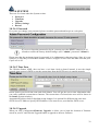
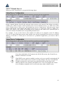
3.8.2.8.5 RIP
• RIP(Enable): Default at Disabled.
• Supply Interval(30seconds): Time among 2 packets RIP
• Expire Timeout(180seconds): Lead time before the timeout
• Garbage Timeout(120 seconds)
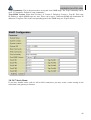
3.8.2.8.6 SNMP
Simple Network Management Protocol (SNMP) is an optional feature that may or may not be
supported by your ADSL Wireless Router ADSL.
SNMP is an application layer protocol that is used for managing networks. SNMP is an optional
feature that may or may not be in the specific firmware that you are working with. There are several
components that make up the SNMP structure, including agents, network management stations
(NMS), network management protocols, and a management information base (MIB). An SNMP agent
is a node that resides on the network, typically a computer or a router. The SNMP agent is controlled
and configured by the NMS by sending SNMP messages between one another. SNMP agents are
logged and identified in a Management Information Base (MIB), in which they are identified by an
object identifiers (OID).
One feature of SNMP is SNMP traps. SNMP traps are used to notify network managers of significant
events that have taken place in the network. These traps are sent to the SNMP NMS (NMS Server
located at Trap IP) through the specified ports.
SNMP System Identification: The System Name, System Contact, System Location, and System
OID are provided to identify the SNMP NMS. The System OID is the ID number placed in all Trap
reports.
The System Name, System Contact, and System Location can be up to 127characters. Default value
for System OID is 1.3.6.1.4.1.4900.
Read Community: This is the password to access public information.The Read Community can be up
to 127 characters. Default is “public.”
Write Community: This is the password to access private information. The Write Community can be
up to 127 characters. Default is “private.”
48
WIRELESS ROUTER ADSL
Trap Community: This is the password to access and view SNMP traps. The Trap Community can be
up to 127 characters. Default is “trap community.”
Trap SNMP Version: Select from Version 1 or Version 2. Default is Version 1. Trap IP: This is the
IP address to which SNMP traps are sent. There can be up to 5 different SNMP trap destination IP
addresses. Trap Port: This is the corresponding port for the SNMP trap (see Trap IP above)
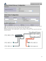
3.8.2.8.7 Static Route
If you have another router with a LAN-to-LAN connection, you may create a static routing on the
router that is the gateway to Internet.
49
WIRELESS ROUTER ADSL
Add: Click this button to add a new static routing. When you click this button, the next figure appears.
Edit: Check the item you want to edit. Then, click the “Edit” button.
Delete: Check the item you want to delete. Then, click the “Delete” button.
Destination Subnet / Dest. Subnet Mask / Gateway Address: Fill in these fields required by this Static
Routing function.
50
WIRELESS ROUTER ADSL
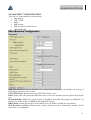
3.8.2.8.8 MISC CONFIGURATION
There are six items under the System section:
• Http Remote
• FTP e TFTP
• DMZ
• DHCP Relay
• PPP reconnect on WAN access
• PPP Half Bridge
Http Server Access: Default at Disabled. Or you may check it and specify the IP address or a group of
IPs (subnet) allowed to access router.
FTP /TFTP/Telnet: Router can act as a FTP/TFTP/Telnet server
DMZ: Enable this and specify the DMZ Host IP to access any incoming request packets from WAN
site.
PPP Half Bridge: Enable this, router will get an IP address from ISP and passing it to behind PC. At
thistime, the router works as a BRIDGE but using PPP to login.
DHCP Relay: Enable this and specify the DHCP server IP address for DHCP relay function.
PPP Reconnect on WAN Access: when a packet from the LAN is addressed to Internet WAN
connection is reestablished.
51
WIRELESS ROUTER ADSL
Connect PPP when ADSL is UP: Check to enable this device to automatically re-establish the
PPPoE/PPPoA session whenADSL is UP.
UPnP: Universal Plug and Play (UPnP) is an architecture for pervasive peer-to-peer network
connectivity of PCs and intelligent devices or appliances, particularly within the home. UPnP builds
on Internet standards and technologies, such as TCP/IP, HTTP, and XML, to enable these devices to
automatically connect with one another and work together to make networking - particularly home
networking – possible for more people.
The UPnP aware applications such as MSN Messenger will discover that they are behind a NAT
router, learn the external IP address and configure port mappings on the router to forward packets from
the external ports of the router to the internal ports used by the application.
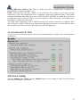
3.8.2.8.9 DIAGNOSTIC TEST
As soon as you enter the test program, all tests will run automatically to diagnose the connection status
of the device.
3.8.3 Save Config
Click the Submit, Save Config and then Submit button to write settings to flash. Then, the system
will reboot for changes to take effect.
52
WIRELESS ROUTER ADSL
Chapter 4
Troubleshooting
If the Wireless ADSL Router is not functioning properly, you can refer first to this chapter for simple
troubleshooting before contacting your service provider. This could save you time and effort but if the
symptoms persist, then consult your service provider.
Problems Starting Up the Wireless ADSL Router
Problem
Corrective Action
None of the LEDs are
on when you turn on
the Wireless ADSL
Router.
Check the connection between the adapter and the ADSL
Firewall Router. If the error persists, you may have a
hardware problem. In this case you should contact technical
support.
Problems with the WAN Interface
Problem
Corrective Action
Initialization of the
PVC connection failed.
Ensure that the cable is connected properly from the ADSL
port to the wall jack. The ADSL LED on the front panel of
the ADSL Firewall Router should be on. Check with your
VPI, VCI, type of encapsulation and type of multiplexing
settings are the same as what you collected from your
telephone company and ISP.
Reboot the Wireless Router ADSL. If you still have
problems, you may need to verify these variables with the
telephone company and/or ISP.
Problems with the LAN Interface
Problem
Corrective Action
Can’t ping any station
on the LAN.
Check the Ethernet LEDs on the front panel. The LED should
be on for a port that has a station connected. If it is off, check
the cables between your Wireless ADSL Router and the
station. Make sure you have uninstalled any software
firewall.
53
WIRELESS ROUTER ADSL
Verify that the IP address and the subnet mask are consistent
between the Wireless Router ADSL and the workstations.
54
WIRELESS ROUTER ADSL
APPENDIX A
Wireless LAN Overview
This section introduces the wireless LAN and some basic configurations. Wireless LANs can be as
simple as two computers with wireless LAN cards communicating in a peer-to-peer network or as
complex as a number of computers with wireless LAN cards communicating through access points
which bridge network traffic to the wired LAN.
Channel
The range of radio frequencies used by IEEE 802.11b wireless devices is called a “channel”. Channels
available depend on your geographical area. You may have a choice of channels (for your region) so
you should use a different channel than an adjacent AP (access point) to reduce interference.
Interference occurs when radio signals from different access points overlap causing interference and
degrading performance.
Adjacent channels partially overlap however. To avoid interference due to overlap, your AP should be
on a channel at least five channels away from a channel that an adjacent AP is using. For example, if
your region has 11 channels and an adjacent AP is using channel 1, then you need to select a channel
between 6 or 11.
ESS ID
An Extended Service Set (ESS) is a group of access points or wireless gateways connected to a wired
LAN on the same subnet. An ESS ID uniquely identifies each set. All access points or wireless
gateways and their associated wireless stations in the same set must have the same ESSID.
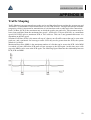
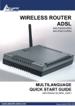
RTS/CTS
A hidden node occurs when two stations are within range of the same access point, but are not within
range of each other. The following figure illustrates a hidden node. Both stations (STA) are within
range of the access point (AP) or wireless gateway, but out-of-range of each other, so they cannot
“hear” each other, that is they do not know if the channel is currently being used. Therefore, they are
considered hidden from each other.
When station A sends data to the ADSL Router, it might not know that the station B is already using
the channel. If these two stations send data at the same time, collisions may occur when both sets of
data arrive at the AP at the same time, resulting in a loss of messages for both stations.
RTS/CTS is designed to prevent collisions due to hidden nodes. An RTS/CTS defines the biggest size
data frame you can send before an RTS (Request To Send)/CTS (Clear to Send) handshake is invoked.
When a data frame exceeds the RTS/CTS value you set (between 0 to 2432 bytes), the station that
wants to transmit this frame must first send an RTS (Request To Send) message to the AP for
55
WIRELESS ROUTER ADSL
permission to send it. The AP then responds with a CTS (Clear to Send) message to all other stations
within its range to notify them to defer their transmission. It also reserves and confirms with the
requesting station the time frame for the requested transmission.
Stations can send frames smaller than the specified RTS/CTS directly to the AP without the RTS
(Request To Send)/CTS (Clear to Send) handshake.
You should only configure RTS/CTS if the possibility of hidden nodes exists on your network and the
“cost” of resending large frames is more than the extra network overhead involved in the RTS
(Request To Send)/CTS (Clear to Send) handshake.
If the RTS/CTS value is greater than the Fragmentation Threshold value (see next), then the RTS
(Request To Send)/CTS (Clear to Send) handshake will never occur as data frames will be fragmented
before they reach RTS/CTS size.
Fragmentation Threshold
A Fragmentation Threshold is the maximum data fragment size (between 256 and 2432 bytes) that can
be sent in the wireless network before the ADSL Router will fragment the packet into smaller data
frames.
A large Fragmentation Threshold is recommended for networks not prone to interference while you
should set a smaller threshold for busy networks or networks that are prone to interference.
If the Fragmentation Threshold value is smaller than the RTS/CTS value (see previously) you set then
the RTS (Request To Send)/CTS (Clear to Send) handshake will never occur as data frames will be
fragmented before they reach RTS/CTS size.
Levels of Security
Wireless security is vital to your network to protect wireless communication between wireless stations,
access points and the wired network.
The figure below shows the possible wireless security levels on your ADSL Router. The highest
security level relies on EAP (Extensible Authentication Protocol) for authentication and utilizes
dynamic WEP key exchange. It requires interaction with a RADIUS (Remote Authentication Dial-In
User Service) server either on the WAN or your LAN to provide authentication service for wireless
stations.
If you do not enable any wireless security on the ADSL Router, your network is accessible to any
wireless networking device that is within range.
Use the ADSL Router web configurator to configurator to set up your wireless LAN security settings.
Refer to the chapter on using the ADSL Router web configurator to see how to access the web
configurator.
56
WIRELESS ROUTER ADSL
Data Encryption with WEP
WEP encryption scrambles the data transmitted between the wireless stations and the access points to
keep network communications private. It encrypts unicast and multicast communications in a network.
Both the wireless stations and the access points must use the same WEP key for data encryption and
decryption.
The ADSL Router allows you to configure up to four 64-bit or 128-bit WEP keys but only one key can
be enabled at any one time.
Configuring Wireless LAN
Click Wireless LAN, Wireless to open the Wireless screen.
The following table describes the labels in this screen.
Label
ESSID
Description
The ESSID (Extended Service Set Identification) is a
unique name to identify the ADSL Router in the
wireless LAN. Wireless stations associating to the
ADSL Router must have the same ESSID.
Enter a descriptive name (up to 32 characters).
Hide ESSID
Select Enable to hide the ESSID in so a station cannot
obtain the ESSID through passive scanning.
Select Disable to make the ESSID visible so a station
can obtain the ESSID through passive scanning.
Channel ID
The range of radio frequencies used by IEEE 802.11b
wireless devices is called a channel.
Select a channel from the drop-down list box.
RTS/CTS
The RTS (Request To Send) threshold (number of
Threshold
bytes) for enabling RTS/CTS handshake. Data with its
frame size larger than this value will perform the
RTS/CTS handshake. Setting this attribute to be larger
than the maximum MSDU (MAC service data unit)
size turns off the RTS/CTS handshake. Setting this
attribute to zero turns on the RTS/CTS handshake.
Enter a value between 0 and 2432.
Fragmentation The threshold (number of bytes) for the fragmentation
Threshold
boundary for directed messages. It is the maximum
data fragment size that can be sent.
Enter a value between 256 and 2432.
WEP Encryption WEP (Wired Equivalent Privacy) encrypts data frames
before transmitting over the wireless network.
Select Disable to allow all wireless computers to
communicate with the access points without any data
encryption.
Select 64-bit WEP or 128-bit WEP to use data
encryption.
Key 1 to Key 4 The WEP keys are used to encrypt data. Both the
ADSL Router and the wireless stations must use the
same WEP key for data transmission.
If you chose 64-bit WEP, then enter any 5 ASCII
characters or 10 hexadecimal characters ("0-9", "AF").
57
WPA-PSK
TKIP
WIRELESS ROUTER ADSL
If you chose 128-bit WEP, then enter 13 ASCII
characters or 26 hexadecimal characters ("0-9", "AF").
You must configure all four keys, but only one key can
be activated at any one time. The default key is key 1.
The key for network authentication. The input format
is in character style and key size should be in the range
between 8 and 63 characters.
TKIP (Temporal Key Integrity Protocol) utilizes a
stronger encryption method and incorporates Message
Integrity Code (MIC) to provide protection against
hackers.
58
WIRELESS ROUTER ADSL
APPENDIX B
Traffic Shaping
Traffic Shaping is an agreement between the carrier and the subscriber to regulate the average rate and
“burstiness” or fluctuation of data transmission over an ATM network. This agreement helps eliminate
congestion, which is important for transmission of real time data such as audio and video connections.
Peak Cell Rate (PCR) is the maximum rate at which the sender can send cells. This parameter may be
lower (but not higher) than the maximum line speed. 1 ATM cell is 53 bytes (424 bits), so a maximum
speed of 832 Kbps gives a maximum PCR of 1962 cells/sec. This rate is not guaranteed because it is
dependent on the line speed.
Sustained Cell Rate (SCR) is the mean cell rate of a bursty, on-off traffic source that can be sent at the
peak rate, and a parameter for burst-type traffic. SCR may not be greater than the PCR; the system
default is 0 cells/sec.
Maximum Burst Size (MBS) is the maximum number of cells that can be sent at the PCR. After MBS
is reached, cell rates fall below SCR until cell rate averages to the SCR again. At this time, more cells
(up to the MBS) can be sent at the PCR again. The following figure illustrates the relationship between
PCR, SCR and MBS.
59
WIRELESS ROUTER ADSL
APPENDIX C
Technical Features
IP, NAT, ARP, ICMP, DHCP(server, relay and client), RIP1/2 ,
SNMP, SNTP client, UPnP, Telnet server
RJ-45, 4 10/100Base-T ports (1 10/100 Base-T port on
LAN port
A02-RA210-W54)
RJ-11 (1 port ADSL)
WAN port
Reset, Power On/Off
External buttons
Power, System, Lan (4), WLAN and ADSL
LED Indicators
Standard ADSL Compliance ANSI T1.413 Issue 2, ITU-T G.992.1(Full Rate DMT), ITU-T
G.992.2 (Lite DMT), ITU-T G.994.1 (Multimode)
RFC2364(PPPoA), RFC2516(PPPoE), RFC1577 e RFC1483
Protocols ADSL
ATM AAL2/AAL5 and ATM service class : CBR, UBR, VBRATM
rt, VBR, ATM Forum UNI 3.0, 3.1 and 4.0
Standard IEEE802.11g e IEEE802.11b
Wireless
Intrusion Detection, DoS, Port Filters, URL blocking, MAC
Firewall
blocking
1 VPN IPSec (IKE, DES/3DES, AH, ESP, MD5/SHA1)
VPN
12V DC @ 1A
Input Power
< 10watts
Power Consumption
CE
Agency and Regulatory
180x 120 x 32 mm
Dimensions
<350g
Weight
Operating Temperature
0℃ to 40℃
Storage Temperature
-10℃ to 70℃
5-95% non-condensing
Operating Humidity
Protocols
60
WIRELESS ROUTER ADSL
APPENDIX D
Support
If you have any problems with the Wireless Router ADSL, please consult this manual.
If you continue to have problems you should contact the dealer where you bought this ADSL Router.
If you have any other questions you can contact the Atlantis Land company directly at the following
address:
Atlantis Land SpA
Viale De Gasperi, 122
20017 Mazzo di Rho(MI)
Tel: +39. 02.93906085, +39. 02.93907634(help desk)
Fax: +39. 02.93906161
Email: [email protected] or [email protected]
WWW: http://www.atlantis-land.com
61