1
VISTAm50
VISTA~5OUL
N5943-4Vl
11 I94
TABLE
OF CONTENTS
ARMING PERIMETER ONLY (STAY). ..............................
ARMING PERIMETER ONLY (INSTANT) ..........................
(AWAY). ..............................
ARMING ALL PROTECTION
ARMING ALL PROTECTION (MAXIMUM) .........................
DISARMING AND SILENCING ALARMS.. .........................
USING THE KEYSWITCH.. ............................................
CHIME
MODE.. ...........................................................
VIEWING CENTRAL STATION MESSAGES.. ....................
PANIC
KEYS.. .............................................................
ACCESS DOOR CONTROL ..........................................
USING #70 RELAY MENU MODE.. ..................................
USING SCHEDULES ....................................................
Delaying The Closing Time.. ......................................
Temporary Open/Close Schedules .............................
..............................
PROGRAMMING DEVICETIMERS..
THE SYSTEM.. ..............................................
TESTING
CONDITIONS..
.............................................
TROUBLE
FIRE ALARM SYSTEM .................................................
.......................................
NFPA RECOMMENDATIONS..
EMERGENCY EVACUATION.. ......................................
MAINTAINING YOUR SYSTEM .....................................
QUICK GUIDE TO SYSTEM FUNCTIONS ........................
SUMMARY OF AUDIBLE NOTIFICATION .........................
GLOSSARY.. ..............................................................
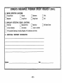
INSURANCE CREDIT REQUEST FORM ...........................
.3
SYSTEM OVERVIEW.. ..................................................
.
A Partitioned System,. ...............................................
.4
Zones ....................................................................
...................................................
4
Burglary Protection
Fire Protection . . . . . . . . . . . . . . . . . . . . . . . . . . . . . . . . . . . . . . . . . . . . . . . . . . . . . . . . . . 5
.5
Alarms ...................................................................
.
Memory of Alarm.. .....................................................
.6
Using Schedules.. ....................................................
.6
Device Timers .........................................................
.6
Accessing other partitions (GOT0 command). ...............
.7
Self-Help Feature.. ...................................................
.7
Phone Access & Voice Response ...............................
.8
ABOUT THE CONSOLES ...............................................
IO
FUNCTIONS OF THE CONSOLES ...................................
12
ENTRY/EXIT DELAYS.. ................................................
13
SECURITY CODES & AUTHORITY LEVELS ......................
13
Duress Code ..........................................................
13
Quick Arming .........................................................
14
Authority Levels.. ...................................................
16
To Add A User ........................................................
18
To Change A Users Code/To Delete A User ..................
19
ACCESSING OTHER PARTITIONS .................................
19
GOT0
Command.. ...................................................
19
Global Arming.. .......................................................
20
CHECKING FOR OPEN ZONES.. ....................................
21
DISPLAYING ALL ZONE DESCRIPTORS.. .......................
22
BYPASSING PROTECTION ZONES ................................
23
Quick Bypass ........................................................
23
Displaying Bypassed Protection Zones .......................
-2-
.24
.25
.26
.27
.28
.29
.30
.31
32
..3 3
.34
.35
.35
.36
..3 9
.41
.43
.45
.46
..4 7
..4 8
..5 0
.52
53
.59
SYSTEM
General
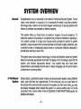
OVERVIEW
Congratulations on your ownership of an Ademco Partitioned Security System. You’ve
made a wise decision in choosing it, for it represents the latest in security protection
technology today. Ademco is the world’s largest manufacturer of security systems and
millions of premises are protected by Ademco systems,
This system offers you three forms of protection: burglary, fire and emergency. To
realize the system’s full potential, it is important that you feel comfortable in operating it.
Your system consists of at least one Console which provides full control of system
operation, various sensors which provide perimeter and interior burglary protection, plus
a selected number of strategically placed smoke or combustion detectors designed to
provide early warning in case of fire.
The system uses microcomputer technology to monitor all protection zones and system
status and provides appropriate information for display on the Console(s) used with the
system,
and initiates
appropriate
alarms. Your system may also have been
programmed to automatically transmit alarm or status messages over the phone lines to
a central alarm monitoring station.
A Partitioned
System
Simply stated, a partitioned system shares one physical alarm system among different
users, each with their own requirements.
For the most part, you as a user need not
know about other users and their structure in the system, but from time to time, you may
see display messages which indicate the system is in use by another user. Do not be
concerned, this is normal. Refer to the ACCESSING OTHER PARTITIONS section for
additional information.
-3-
SYSTEM
Zones
Burglary
Protection
OVERVIEW
Your system’s sensing devices have been assigned to various “zones.” For example,
the sensing device on your Entry/Exit door may have been assigned to zone 01,
sensing devices on windows in the master bedroom to zone 02, and so on. These
numbers will appear on the display, along with an alpha descriptor for that zone (if
programmed), when an alarm or trouble condition occurs.
The burglary protection portion of your system must be turned on or “armed” before it
will sense burglary alarm conditions. Your system provides four modes of burglary
protection: STAY, AWAY, INSTANT and MAXIMUM, and even allows you to BYPASS
selected zones of protection while leaving the rest of the system armed. The system
also provides a CHIME mode, for alerting users to the opening and closing of doors and
windows while the system is disarmed. Refer to the other sections of this manual for
procedures for using these features.
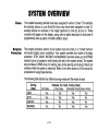
The following table lists the four different arming modes and the results of each.
Arming
Mode
AWAY
STAY
INSTANT
MAXIMUM
Exit Delay
Yes
Yes
Yes
Yes
-4-
Features For Each Arming Mode
Enty Delay
Perimeter Armed Interior Armed
Yes
Yes
Yes
Yes
Yes
No
Yes
No
No
Yes
No
Yes
SYSTEM
OVERVIEW
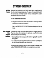
Fire Protection
The fire protection portion of your security system (if used) is always on and will sound
an alarm if a fire condition is detected. Refer to the FIRE ALARM SYSTEM section for
important
information
concerning
fire protection,
smoke detectors and planning
emergency exit routes from your house.
Alarms
When an alarm occurs, both the console and external sounders will sound, and the
console will display the zone(s) causing the alarm. If your system is connected to a
central monitoring station, an alarm message will also be sent. To stop the alarm
sounding, simply disarm the system.
Memory of
Alarm
When an alarm condition occurs, the console displays the number(s) of the zone(s) that
caused the problem, and displays the type of alarm (ex. FIRE, ALARM). It remains
displayed until it is cleared by disarming the system (see DISARMING THE SYSTEM
section).
-5-
SYSTEM
Using Schedules
Device
Timers
OVERVIEW
your system may have been Pwvammed with schedules for automatically arming,
disarming and activating various devices and/or performing other system functions at
predetermined times. Users can modify some of these schedules by manually
delaying a closing time, using temporaty schedules, or by programming special user
schedules. Refer to the USING SCHEDULES section at the end of this manual for
scheduling related procedures.
The system provides up to 20 “timers” which can be used to control various devices, such
as lights or appliances. These timers are similar in concept to the individual appliance timers
that might be purchased at a department store. The devices that can be controlled are
programmed into the system by the installer. Up to 16 of these devices can be
programmed. Refer to the PROGRAMMING DEVICE TIMERS section for procedures.
To Access Another
partition
(GOTO Command)
Each console is as.+gned a ,default partition for display purposes, and will show
only.that partition’sInformation. But, If the user is authorized, a console .in one
PadltlonCan be used to Perform sYstem functions in another Partition by usln9 the
GOTO command. Note that only those partitions authorized and programmed by the
installer can be accessed in this manner.
❑
foIlowed by
To GOTO another partition, enter your security code, then press
the desired partition number (1-8).
The console will remain in the new partition until directed to go to another partition, or
until 120 seconds has elapsed with no keypad activity. Entering partition number O
will return the console to its original partition.
-6-
SYSTEM
Self-Help
Feature
OVERVIEW
Abbreviated user’s instructions are built into the system that can be easily viewed on
the alpha console’s message display screen. This feature will prove particularly useful if
this manual is not conveniently
accessible when you need to perform a system
procedure with which you are not familiar.
To view the abbreviated
instructions:
1. Simply press and hold down the function key of interest until the description starts to
appear (about 5 seconds) and then release it.
Refer to the FUNCTIONS
function.
Phone Access &
Voice
Response
capabiii~
OF THE CONSOLE
section for descriptions
of each key
Your system may include a voice module that will permit you to access the system via a
Touch-tone phone, either on-premises or by call-in when away. The phone access
feature will enable you to do the following:
. Receive
security
●
synthesized
system.
vofice messages
over the telephone
regarding
Arm and disarm the system and perform most function commands
with voice confirmation provided after each command entry.
the status of the
via the telephone,
Complete information regarding the use of this feature is provided in a separate manual
entitled PHONE ACCESS USER’S GUIDE, which accompanies the voice module.
-7-
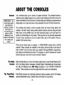
ABOUT
General
IMPORTANT: If the
console beeps rapidly
upon entering the
premises, it indicates
that an alarm has
occurred during your
absence. LEAVE
IMMEDIATELY and
CONTACT THE POLICE
from a nearby safe
location.
THE
CONSOLES
Your consoles allow you to control all system functions. The consoles feature a
telephone style (digital) keypad and a Liquid Crystal Display (LCD) which shows the
nature and location of all occurrences. Console display back lighting is programmable to
always stay on or to light only when a key is pressed, then turn off a few minutes later.
The consoles also feature a built-in sounder which will sound during alarms and
troubles. It will also “beep” during certain system functions, such as during entry/exit
delay times, during CHIME mode, and when depressing keys to arm and disarm the
system (to acknowledge the key press). These sounds can be optionally suppressed
in some of your consoles (so as not to disturb other users of the system). Ask your
installer if this has been done,
There are two basic types of consoles – a FIXED-WORD
console. These consoles are available in two styles, shown
either of which may have been used in your system. Although
both styles are functionally the same. The keypads on style
behind a flip-down cover which can be removed, if desired.
The Alpha
Console
The Fixed-Word
Console
console and an ALPHA
as style A and style B,
different in appearance,
B consoles are located
Alpha consoles feature a 2-line, 32 character alphanumeric Liquid Crystal Display (LCD)
which can display system messages in friendly English. Abbreviated user’s instructions
can also be displayed (see Self Help paragraph
in the SYSTEM OVERVIEW
section). These consoles can also be programmed with custom zone descriptors.
Fixed-Word consoles are functionally identical to alpha consoles, but the LCD display
uses pre-designated words to identify nature and location of occurrences.
-8-
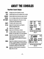
ABOUT
Fixed-Word
AWAW
STAY:
INSTANT:
BYPASS:
NOT READY:
READY:
NO AC:
AC:
CHIME
BAT:
ALARM:
CHECK:
FIRE:
Console
THE
CONSOLES
Displays
All burglary zones, interior & perimeter, are armed.
Perimeter burglary zones, such as windows& doors, are armed.
Perimeter burglary zones armed and entry delay is turned off.
One or more burglary protection zones have been bypassed.
Appears when burglary portion of the system is not ready
for arming (due to open protection zones).
The burglary system is ready to be armed.
Appears when AC power has been cut off. System is
operating on backup battery power.
Appears when AC power is present.
Appears when the CHIME feature is activated.
Low battery condition in a wireless sensor (if ID number
displayed) or low system battery (if no ID number displayed).
Appears when an intrusion has been detected and the
system is armed (also appears during a fire alarm or
audible emergency alarm). Accompanied by the protection
zone ID in alarm.
Appears when a malfunction is discovered in the system at
any time or if a trouble is detected in a FIRE zone at any time
or in a DAY/NIGHT burglary zone during a disarmed period.
Accompanied by a display of zone number in trouble.
Appears when a fire alarm is present. Accompanied by a
display of the zone in alarm.
-9-
m
AWAY
STAY
A~RM
INSTANT
CHECK
FIRE
‘YPASS
NOT READY
NO AC
CHIME
BAT
FIXED-WORDCONSOLEDISPLAYWINDOW
(STYLE“A”)
u~AwAY
BYPASS
NOAC
ALARM ST’Y
::;:=B%
FIRE CHECK INSTANT
FIXED-WORDCONSOLEDISPIAY WINDOW
(STYLE“B”)
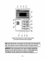
FUNCTIONS
OF
THE
1. ALPHA DISPLAY WINDOW: A 2-line, 32-character LiquidCrystal
9.
Display (LCD). Displays protectionpointidentificationand system
status,messages,and userinstructions.
2
3.
~
KEY: Disarmsthe burglaryportion of the system, silences
alarms and audible trouble indicators, and clears visual alarm trouble
after the problem has been corrected.
10.
Completely arms both perimeter and interior
m
‘Ey:
burglary protection for backup protection by sensing an intruder’s
movements through protected interior areas as well as guarding
protected doors, windows, etc. Late arrivals can enter throughan
11,
12.
13.
14.
sounds an alarm if one is opened. Interior protection is not armed,
which allows movement within your house without causing an alarm.
Late arrivals can enter through an entry delay zone withoutcausing an
alarm if the system is dkarmed before the entry delay time expires.
\_M_/
KEY: Arms in manner similar to AWAY mode, but
eliminates the entry dalay period, thus providing maximum protection.
An alarm will occur immediately upon opening any protection point,
including entry delay zmes.
6.
1=~
7.
[~]
KEY: Removes individual protection zones from being
monitored by the system. Displays previously bypassed protection
zcnes.
8.
1~~
KEY: Armsin mannersimilart.STAY mode,butturns
offtha entrydelaypertod,offeringgreatersecuritywhileinsideand not
expectingany late arrivals. An alarm will occur immediately upon
KEY: Tests thesyetemandalarm
-]
KEY:
be
Turns on& off the C1-lihrlEmode. When on, any
-~
KEY: When depressed priorto armingthe system,the
consolewilldisplay all open protectionzones withh the console’s
home partition.This key is also used to display all zone descriptors
that have been programmed for your system, by holdingthe key down
for at least 5 seconds.
{~]
KEY: Arms the perimeter burglary protection,guarding
protecteddoors,windows and other perimeter protection points, and
5.
-[
KEY Allows the entry of additional usercodesfhatcan
given to ofher users of the system.
entry through a protected delay or perimeter zone while the system is
dlsanmed WIIIcause atone to sound at the Console(s).
entrydelay zone withoutcausingan alarmif the systemis dkarmed
beforethe entrydelaytimeexpires.
4.
CONSOLE
15.
16.
sounder if disarmed.
17.
opening any perimeter protection point, including entry delay zones.
10-
❑ KEY:
PermksAWvtlNG
of the system without use of asec.rity
code (“Quick Arm”, if programmed).
KEYS 0-9 Used to enter your indvidual security access code(s).
POWEWREADY
INDICATOR:
(GREEN) On some consoles, this
lights when primary power is on: If off, s“stem is operatin on its
backup battery power. CALL YOUR lNSTA~LER lMMEDIAT#LY. On
other wpes of consoles, lit indicates system is ready to be armed,
while uh”litindicates system not ready.
ARMED INDICATOR: (RED) Lit when the system has been armed
(STAY, AWAY, INSTANT or MAXIMUM).
INTERNAL SOUNDER:
Source of audible internal warning and
confirmation sounds, as well as alarms (see “Summary of Audible
Notifications”).
A-B-C PANIC KEYS:
Refer to the PANIC KEYS section for
descriptions of these keys.
@
/
\
ARMEO
@w
w
E
,
,
/0
r
READ,
/7 o
-49
---10
0
‘
012
Typical Style “B Alpha Console shown above. Fixed-work consoles are functionally
the same except for screen displays and emergency key configuration.
Note: Unless stated otherwise, most procedures in this manual apply to all console types and
styles. Some procedures, however, are specifically intended for use by alpha consoles only.
Tf . Wh en using the keypad to enter codes and commands, sequential key
depressions must be made within 3 seconds of one another. If 3 seconds elapses without
a key depression, the entry is aborted and must be repeated from its beginning.
-11-
ENTRY/EXIT
General
Information
DELAYS
Your system has preset time delays, known as exit delay and entry delay. Whenever
you arm your system, exit delay gives you time to leave through the designated exit
door without setting off an alarm. Exit delay begins immediately after entering any arming
command, and applies to all modes of arming protection. [f programmed, a slow beeping
will sound throughout the exit delay period.
Entry Delay gives you time to disarm the system when you reenter through the
designated entrance door. But the system must be disarmed before the entry delay
period ends, or an alarm will occur. The console will beep during the entry delay period,
reminding you to disarm the system. You can also arm the system with no entry delay at
all by using either INSTANT or MAXIMUM arming modes. These modes provide greater
security while on the premises or while away for extended periods of time. See your
installer for your delay times.
-12-
SECURITY
CODES
General
Information
&
AUTHORITY
LEVELS
At the time of installation, you were assigned an authority level and a personal four-digit
security code, known only to you and yours. The security code must be entered when
arming and disarming the system. The authority level defines the system functions that
you can perform.
As an additional safety feature, other users that do not have a need to know your code
can be assigned different security codes, and each user can be given a different
authority level. Users are identified by “user numbers”, which are assigned when
assigning a user’s security code.
All codes can be used interchangeably
limits of each code’s authority level (a
disarmed by another user’s code), with
See AUTHORITY
LEVELS section on
regarding user authority levels.
Duress
Code
This feature is intended for use when you are forced to disarm or arm the system under
threat. When used, the system will act normally, but can silently notify the central station
of your situation, if that service has been provided. The duress code is pre-assigned
by the installer during installation (authority level 6).
Important:
Quick Arming
when performing system functions within the
system armed with one user’s code can be
the exception of the Operator Level C code.
the following page for detailed information
This code is useful only when the system is connected
to a central station.
❑
key can be pressed
Note that if “Quick Arming” was programmed by the installer, the
in place of the security code when arming the system. The security code must always
be used to disarm the system, however.
–13-
SECURITY
Authority
CODES
Levels
&
AUTHORITY
LEVELS
Authority levels define the system functions a particular user can perform. Depending on
the authority assigned to you, there are certain system functions you maybe prohibited
from performing. In summary, there are six authority levels, each having certain system
restrictions as shown below.
Level 1 Master:
Can perform all system functions in assigned partitions, and
can add, delete or change Manager and Operator level users.
Master codes are added by the Installer.
Level 2 Manager:
Can perform system functions in assigned partitions, and can
add, delete or change Operator level users.
Level 3 Operator
A: Can perform system functions in assigned partitions, but
cannot add or delete other users.
Level 4 Operator
B: Same as Operator A, except Operator B cannot bypass
zones of protection.
Level 5 Operator
C: Can arm the system in assigned partitions, but cannot disarm the
system unless the system was armed with this code. This code
is typically assigned to someone who has a need to arm/disarm
the system only at certain times (such as a baby-sitter).
Level 6 Duress:
Can arm and disarm the system, but also sends a silent panic
alarm to the central station, if that service is connected.
To view your
1.
authority
Enter your code+
level and system
capabilities:
❑ + ❑.
The console will display the partition(s) that you are authorized to operate, and your
user number and authority level in each partition.
-14-
SECURITY
General Rules
on Authority
Levels and
Changes
CODES
●
●
●
●
●
●
●
&
AUTHORITY
LEVELS
A user may not delete or change the user code of the SAME or HIGHER authority than
which he is assigned.
A user may only ADD users to a LOWER authority level.
A user may assign access codes only to those partitions to which the user adding the
code has access. (ex. a user with access to only partition 1 cannot assign codes in
partition 2.)
The only way to assign a user’s authority level is by using the “Add A User”
procedure. To change a user’s authority level, that user must first be deleted, then
added again.
A user can only be DELETED or CHANGED from within the partition he is assigned.
User numbers must be entered as 2-digit entries. Single digit user numbers must be
preceded by a “O” (example, 03, 04, etc.). Security codes are entered as 4-digit
numbers.
Before assigning a security code, be sure it does not conflict with any DURESS code.
Note: When adding, changing or deleting users, all other alpha consoles in that partition
will display “User Edit Mode – Please Stand By”, and key depressions (except Panic)
at those consoles will be ignored. Panic key depressions will cause an alarm and
terminate user entry.
To Exit User Edit
Mr)de
You can exit any of the user edit modes described
by doing the following:
1.
Press either ~
or
❑, or don’t
-15-
on the following pages at any time
press any key for 10 seconds.
SECURITY
To Add a User
CODES
&
AUTHORITY
LEVELS
IMPORTANT: Temporary users should not be shown how to use any system function
they do not need to know (e.g. bypassing protection zones).
CODE
key.
❑
1.
Enter Master or Manager code and press the
2.
Enter the new user’s 2-digit User Number (01-99).
3.
Enter 4-digit security code for that user. The following prompts will appear.
Enter 1 to add a new user code. Entering O will change the
existing user’s code to the code entered in step 3. See
IJ=NL?,7=YE5
Changing A User’s Code section.
I
I L15ERMIR8ER=3
I ENTERWTH.LEUEL
I
RFBUTTDN?
L?= no. 1= YES
EYE-1
I
I
I
Enter the authority level, 1-6, for this user within this partition.
1=master
3=operator A 5=operator C
2=manager
4=operator B 6=duress code
This prompt will appear if a 5800 series button transmitter has
been supplied and has not yet been assigned to a user,
Press 1 if a button transmitter will be assigned to this user.
Otherwise press O.
If assigning a button transmitter, this prompt will appear. Enter
the button’s zone number (see your installer for zone
number).
-16-
SECURITY
to
Add a User
(continued)
CODES
m
&
AUTHORITY
LEVELS
If you as a usel I ItUJe excess to other partitions, the console
will prompt for ability of this new user to access (GOTO)
those partitions. Press O (NO) or 1 (YES). If no, the system
activates this user code and exits “Add a User” mode. If yes,
the console prompts for the Global Arm option for this user.
Press 1 (YES) if this user will be allowed to arm more than
one partition. Press O if this user will arm only his assigned
pa.itbn.
IEE!ZEl
EEEl
The console now prompts for the user’s access to the next
partition (see GOTO command). Again press O or 1. If yes,
the system will automatically assign a user number for use in
that partition and will prompt for the authority level and global
arm option for this user within the partition (see previous
steps).
R
When all partitions have been displayed, the console will
scroll through the partition(s)
to which access has been
assigned, and will display the user number, authority level
and global arm option for each. The “G” after the authority
level indicates that the global arm feature is active for this user
in the displayed partition. The “*” indicates the partition from
which this user can be changed or deleted. The” .“ at the end
of the second line indicates that this user sends open/close
reports. Open/close reporting is automatically active for any
users added by you, if you have operdclose reporting active.
-17-
SECURITY
To Changea
User% Code
CODES
1.
&
AUTHORITY
Enter Master or Manager code and press the
LEVELS
CODE
key+ user number to be changed.
❑
2. Enter the new code for that user.
The system will recognize that the user number is already in use
and will prompt whether or not this is a new user. Enter O to
change the existing user’s code to the code entered in step 3.
-
E
To Delete a
User
The system will confirm that the change is allowed based on
authorization level, and if so, will put the new code into effect.
Note that if changing
one’s own code, the system will
prompt for the new code to be reentered. This prevents
accidentally changing a high level code.
1. Enter Master or Manager code and press the
CODE
key+ User Number to be deleted.
❑
2. Enter Master or Manager code first entered.
The system will recognize that the User number is already in
use and WIII prompt to confirm that it should be deleted. Press
=
O@fO)orl(
YES).
If yes, that user’s code will be removed from all partitions to
which it was assigned, and all authorization levels and other
information about that user will be deleted. Note that a user can
only be deleted from the partition in which it was first assigned,
and can only be deleted by a user with a higher authority level.
A User’s security code cannot be deleted by oneself.
E!rl
-18-
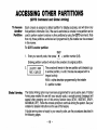
ACCESSING
OTHER
(GOTO Command
To Access
Another
Partition
Each console
PARTITIONS
and Global Arming)
is assigned
a default partition for display purposes, and will show only
But, if the user is authorized, a console in one partition can be
used to perform system functions in other partitions by using the GOTO command. Note
that only those partitions authorized and programmed by the installer can be accessed
in this manner.
that partition’s information.
To GOTO another
partition:
READY
1. Enter your security code, then press ~
+ partition number (O-8).
Entering partition number O will return the console to its original partition.
2“-
The console will remain in the new partition until directed to go
to another partition, or until 2 minutes has elapsed with no
~eypadactivi~
AAAA = alpha descriptor programmed
X = partition number
Global Arming
by the installer
The Global Arming option may have been programmed for use by some users. If Global
Arming was enabled for use with your security code, a console prompt (message) will
appear after pressing one of the arming function keys (STAY, INSTANT, AWAY,
MAXIMUM, OFF). Follow the console prompts to continue arming the system. See your
installer for detailed instructions on the use of this feature.
If global arming does not apply to your security code, use the procedures described in
the following pages,
-19-
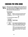
CHECKING
Using the ~
READY Key
FOR
OPEN
ZONES
Before arming your system, all protected doors, windows and other protection zones
must be closed or bypassed (see BYPASSING section). Otherwise the console will
display a “Not Ready” message. Using the READY key will display all zones that are
faulted, making it easier for you to secure any open zones.
To show faulted
zones:
Note: Some consoles light a green LED when the system
is ready. If not lit, the system is not ready to be armed.
E
READY
1. Do not enter security code, but simply press
~
.
EE&&-1
Typical
fault display
2“LZZEI
Secure or bypass the zones displayed before arming the
system. The “Ready” message will be displayed when all
protection zones have been either closed or bypassed.
t NOTE: All or part of this message maybe replaced by a customized
message programmed by the installer. Bear this in mind whenever the
instructions indicate that the “DISARMED” or” READY” message will be
displayed.
-20-
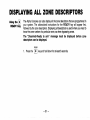
DISPLAYING
ALL
❑
Using the
READY Key
ZONE
DESCRIPTORS
The Alpha Consoles can also display all the zone descriptors that are programmed in
your system. The abbreviated
instructions
for the READY
key will appear first,
followed by the zone descriptors. Displaying all descriptors is useful when you need to
know the zone number of a particular zone, as when bypassing zones.
The “Disarmed-Ready
to arm”
descriptors
can be displayed.
message
must
be displayed
READY
1.
Press the
~
key and hold down for at least 5 seconds,
-21-
before
zone
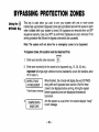
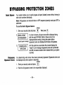
BYPASSING
❑
Using the
BYPASS Key
ZONES
PROTECTION
This key is used when you want to arm your system with one or more zones
intentionally unprotected. Bypassed zones are unprotected and will not cause an alarm
when violated while your system is armed. All bypasses are removed when an OFF
sequence (security code plus OFF) is performed. Bypasses are also removed if the
arming procedure that follows the bypass command is not successful.
Note: The system
To bypass
will
not allow
zones, the system
fire or emergency
must
be disarmed
zones to be bypassed.
first.
BYPASS
1. Enter your security code and press
❑
.
Enter zone number(s) for the zones to be bypassed (e.g., 01, 02,03, etc.).
Important! All single-digit numbers must be preceded by a zero (for example, enter
01 ‘for zone 1).
-
2.
B~/7355~lF~OflT
LIPST/71RS8EL?ROOfl
I
Typical bypass message
4.
I
L?1517RREOBYPRS5
RE131Y TOt?RI’/
I
When finished, the console will display the word BYPASS
along with each bypassed zone number. Wait for these
zones to be displayed before arming. Arming the system
before bypassed zones are displayed eliminates all
bypasses.
Arm the system as usual when the console displays “ready”
to arm message.
-22-
BYPASSING
Quick Bypass
Your system allows you to easily bypass all open (faulted)
enter zone numbers individually.
Note: All bypasses
perfonmed.
To use the Quick
1.
are removed when an OFF sequence
Bypass
I
Typical bypass message
3“
E!imzl
Displaying
Zones
feature:
Enter your security code and press
2. ~ypf155D7FplJflT
tiPSTW?58El?RUU/7 I
Bypassed
ZONES
PROTECTION
having to
(security code plus OFF) is
BYPASS
❑
zones without
then press
❑.
In a few moments, all open zones will be displayed along
with the word BYPASS. Wait for these zones to be
displayed before arming. Arming the system before
bypassed zones are displayed eliminates all bypasses.
Arm the system as usual when the console displays the
“ready” to arm message. Bypassed zones are unprotected
and will not cause an alarm when violated while your system
is armed.
For determining what zones have been previously
be displayed only when system is disarmed.
bypassed.
BYPASS
1.
Enter your security code and press
2.
Wait for all bypassed zones to be sequentially
-23-
~
.
displayed.
Bypassed
zones can
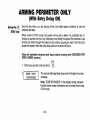
ARMING
PERIMETER
ONLY
(With Entry Delay ON)
❑
Using the
STAY key
Use this key when you are staying
entrance door later.
home,
but might expect
someone
to use the
When armed in STAY mode, the system will sound an alarm if a protected door or
window is opened, but you may otherwise move freely throughout the premises. Late
arrivals can enter through the entrance door without causing an alarm, but they must
disarm the system within the entry delay period or an alarm will occur.
Close all perimeter
windows
OPEN ZONES section)
and doors
before
arming
(see CHECKiNG
FOR
STAY
1.
Enter your security code and press
‘REzZ1
❑
.
The console will beep three times and will display the armed
n-lf=swe
Note: “ZONE BYPASSED” in this display simply indicates
that the interior zones of protection are not armed when using
STAY mode.
-24-
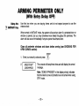
ARMING
PERIMETER
ONLY
(With Entry Delay OFF)
•17
Using the
INSTANT
Key
Use this key when
entrance door.
you are staying
home and do not expect
anyone
to use the
When armed in INSTANT mode, the system will sound an alarm if a protected door or
window is opened, but you may otherwise move freely throughout the premises. The
alarm will also sound immediately if anyone opens the entrance door.
Close all perimeter
windows
OPEN ZONES section)
and doors
before
arming
(see CHECKING
FOR
INSTANT
1.
Enter your security code and press
2“EE!izLl
‘esSage
❑
.
The console will beep three times and will display the armed
Note: “ZONE BYPASSED” in this display simply indicates
that the interior zones of protection are not armed when using
STAY mode.
-25-
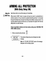
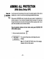
ARMING
ALL
PROTECTION
(With Entry Delay ON)
2
El
Using the
AWAY- Key
Use this key when no one will be staying on the premises.
When armed in AWAY mode, the system will sound an alarm if a protected door or
window is opened, or if any movement is detected inside the premises. You may leave
through the entrance door during the exit delay period without causing an alarm. You
may also reenter through the entrance door, but must disarm the system within the entry
delay period or an alarm will occur.
Close all perimeter
windows
OPEN ZONES section)
and doors
before
arming
(see CHECKING
FOR
AWAY
1.
Enter your security code and press
2.
FiR17ED““WHY”*
[
90U??WEx/TlwJ
I
❑
.
The console will beep twice and will display the armed
message.
I
Note: The “YOU MAY EXIT NOW” portion of the message
disappears when exit delay expires.
-26-
ARMING
ALL
PROTECTION
(With Entry Delay OFF]
4
❑
Using the
MAXIMUM
Key
Use this key when the premises will be vacant for extended periods of time such as
vacations, etc., or when no one will be moving through protected interior areas.
When armed in MAXIMUM mode, the system will sound an alarm if a protected door or
window is opened, or if any movement is detected inside the premises. You may leave
through the entrance door during the exit delay period without causing an alarm, but an
alarm will be sounded as soon as someone reenters.
Close all perimeter
windows
OPEN ZONES section)
and doors
before
arming
(see CHECKING
FOR
MAXIMUM
1.
Enter your security code and press
❑
2“EZEZI‘esSage<
.
The console will beep twice and will display the armed
Note: The “YOU MAY EXIT NOW” portion of the message
disappears when exit delay expires.
-27-
DISARMING
Using the
❑ OFF
Key
AND
SILENCING
ALARMS
The OFF key is used to disarm the system and to silence alarm and trouble sounds.
See “SUMMARY OF AUDIBLE NOTIFICATION” section for information which will help
you to distinguish between FIRE and BURGLARY alarm sounds.
IMPORTANT:
if you return and the main burglary sounder is on, DO NOT enter the
premises, but call the police from a nearby safe location. If you return after an alarm has
occurred and the main sounder has shut itself off, the console will beep rapidly upon
LEAVE
entering,
indicating
that an alarm has occurred
during your absence.
IMMEDIATELY and CONTACT THE POLICE from a nearby safe location.
To disarm
1.
the system
burglary
OFF
or fire alarms:
Enter your security code and press ~.
EiEl
Memory of
Alarm
and silence
The Ready message will be displayed (if no alarms have
occurred while armed) and the console will beep once to
confirm that the system is disarmed.
The console displays the zone number and type of alarm for any zone that has an
alarm condition. These messages will remain displayed until cleared by a user. If an
alarm has occurred, note the zone number displayed on the console and repeat step 1
above to clear the “Memory of Alarm” and restore the Ready message display. If the
Ready message will not display, go to the displayed zone and remedy the fault (close
windows, etc.). If the fault cannot be remedied, notify the alarm agency.
If the system was armed when the alarm occurred,
the system, a second time to clear the display.
-28-
repeat step 1 twice: once to disarm
USING
General
Arming
THE
KEYSWITCH
Your system may be equipped with a keyswitch for use when arming and disarming. A
red and green light on the keyswitch plate indicate the status of your system as follows:
Green
Light:
Red
Lit
Slow
Rapid
Light:
Steady:
Flashing:
Flashing:
Lights when the system is disarmed and ready to be armed (no
open zones). If the system is disarmed and the green light is off,
it indicates the system is not ready (one or more zones are
open).
Lights when system is armed or memory of alarm exists.
System is armed in AWAY mode.
System is armed in STAY mode.
Memory of alarm, indicating an alarm has occurred.
To arm in the AWAY mode, turn the key to the
right for 1/2 second and release. Consoles will
beep twice and the red light will stay on steady.
To arm in the STAY mode, turn the key to the
right and hold for longer than 3 seconds, then
release. Consoles will beep three times and the
red light will flash slowly.
Disarming
To disarm the system, turn the key to the right
and release. If an alarm has occurred, the red light
will be flashing rapidly (memory of alarm).
-29-
CHIME
Using the ~
Key
MODE
Your system can be set to alert you to the opening of a door or window while it is
disarmed by using CHIME mode. When activated, three tones will sound at the
Console whenever a protected perimeter door or window is opened, and the Not Ready
message will be displayed. Pressing the READY key will display the open protection
points.
Note that Chime mode can be activated only when the system is disarmed.
CHIME
1. To turn Chime Mode on, enter the security code and press
m
❑
.
The CHIME MODE ON message will appear for about two
seconds then disappear. To display this message again (to
determine whether chime mode is on or off), simply press and
hold down the CHIME key for 5 seconds.
CHIME
2,
To turn Chime Mode off, enter the security code and press
m
~
again.
The CHIME MODE OFF message will appear for about two
seconds then disappear. To display this message again (to
determine whether chime mode is on or off), simply press and
hold down the CHIME key for 5 seconds.
-30-
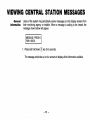
VIEWING
General
Information
CENTRAL
STATION
Users of the system may periodically
their monitoring agency or installer.
message shown below will appear.
1. Press and hold down
receive messages
When a message
MESSAGES
on their display screens from
is waiting to be viewed, the
❑ key for 5 seconds.
The message could take up to four screens to display all the information available.
-31-
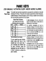
PANIC
KEYS
(FOR MANUALLY ACTIVATING SILENT AND/OR AUDIBLE ALARMS)
Using
Panic Keys
Your system may have been programmed to use special key combinations to manually
activate panic functions. The functions that might be programmed are Silent Emergency,
Audible Emergency, Personal Emergency, and Fire. See your installer for the function(s)
that may have been programmed for your system.
Active Panic Functions
A silent emergency will send a silent alarm
(your installer should note which
signal to the central station, but there will be no
function(s) is active in your system)
audible alarms or visual displays.
Keys
Zone
t-unction
An
audible
emergency
will send an
95
1 and*
emergency message to the central station (if
3 and #
96
connected) and will sound a loud, steady alarm at
your console and at any external sounders that
* and #
99
may be connected (ALARM
plus a zone
A*
95
would
also
be
displayed).
number
B“
99
A personal
emergency alarm will send an
c’
96
% May not be present on your c6neole(s).
emergency message to the central station (if
..
connected) and wil[sound at Consoles, but not
To use a paired key panic function,
at external bells or sirens. (ALARM plus a zone
simply
press
both
keys of the
number would also be displayed)
assigned
pair at the same time. If
A fire alarm will send a fire alarm message to
your
console(s)
have lettered keys
press
the
for
panic
functions,
designated
key and hold down for
at least 2 seconds to activate the
panic function.
-32-
the central
station
and will uniquely
sound
external bells and sirens (FIRE plus a zone
number would also be displayed).
ACCESS
General
Information
DOOR
CONTROL
Your system may be setup such that a locked access door (such as in a lobby) can be
unlocked using a console command. Ask your installer if this has been done in your
system.
To activate this relay:
1.
Enter your security code and press
The door will unlock for 2 seconds.
-33-
❑.
USING
General
Information
#70
Your system
RELAY
MENU
MODE
may be set up so that certain lights or other devices can be turned on or off by
using the #70 command from either a console or a telephone keypad (if voice module is used).
Ask your installer if this has been done in your system.
To activate relays from a console keypad, enter 4-digit security code + [#] +70. Follow
the console prompts described below.
To activate relays using a telephone and voice module, first dial the 2-digit phone
access code. When the system acknowledges the access, enter 4-digit security code + [#] +
70. The following promptshoice responses will begin.
Voice: “ENTER DEVICE CODE NOW
=[
Voice: “voice descriptor DEVICE
ml
I
Enter the 2-digit number of the device to be activated.
Note that if an invalid number is entered, the system will simply ask
you to reenter the number.
ENTER 1, FOR voice descr@orOFF
nn ON/OFF,
FOR voice descriptor ON
ENTER O
Press O or 1 to turn the device off or on respectively.
the 2-digit device number and voice descriptor is the
relay voice descriptor programmed by the installer.
“nn” represents
Voice: “voice descriptor DEVICE nn ON/OFF.
m[
TO EXIT ENTER 00 NOW”
press * to continue. The ENTER
DEVICE NO. prompt will appear.
From a telephone keypad, enter 00 to exit, or enter the next
relay number to be programmed. The current on/off state of that relay
will be annunciated as described above. Alternatively, if 6 seconds
elapses with no key depression, the voice module will annunciate the
“ENTER DEVICE CODE NOW message.
-34From
a console
keypad,
1
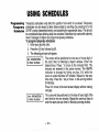
USING SCHEDULES
Delaying
the Closing
Time
Your system’s programmed
schedules may automatically
arm the system at a
Prdetwrnined time.in the Gventa Usermuststayon the premiseslaterthan usual,
usc is with master or manager authority levels can manually delay the automatic
arming (closing) time up to 2 hours.
To delay the closing time
1. Enter your security codo (master or manager authority levels only).
key, followed by 82.
2. Press the
3. A menu prompt will be displayed, asking for the number of hours of delay.
Enter the desired number of hours of delay, 1 or 2. The
system will automatically exit this mode after entry.
m ote t at t e e ay is from the scheduled closing time, not from the time the
command is entered.
important:
The selected delay cannot be reduced once it is set. A 1 hour
delay can be increased to 2 hours, though.
4. The system will automatically send a message to the central station informing
them that the programmed schedule has been changed.
❑
-35-
USING SCHEDULES
7emPoraW
Open/Close
Schedules
Temporary schedules allow you to override the normal schedules programmed by
the install=-Ternwary schedulesCanbe in effectfor UP to one week, and take
effectas soon as theY are programmed”
Schedules are comprised of an arming (closing) time window and a disarming
(opening) time window. A time window is simply a defined period of time, at the end
of which arming or disarming will occur.
Before programming a temporary schedule, use a worksheet similar to the one below
to plan your schedule. This will make it easier when actually programming the
schedule.
ArmlDisarm Windows
Disarm Window
StartTime HH:MM
StopTime HH:MM
Arm Window
Statt Time HH:MM
StopTime HH:MM
Mon
-36-
Tue
Wed
Thu
Fri
Sat
Sun
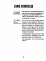
USING SCHEDULES
Programming
Temporary
Schedules
Temporary schedules only affect the partition from which it is entered. Temporary
schedules can be reused at later dates simply by scrolling (by pressing #) to the
DAyS? prowt (describedbelow)and activatiw the appropriatedays. ?his should
be considered when defining daily time windows. Note that only users wdh authority
level of manager or higher can program temporary schedules.
To program temporary schedules:
1. Enter your security code.
2.
3.
❑
key followed by 81,
Press the
The following prompts will appear.
The cursor will be positioned on the tens of hours digit of
the start time for Monday’s disarm window. Enter the
desired hour. Press * to move to the minutes field. The
minutes are entered in the same manner. The AM/PM
indication is changed
by hitting any key, O-9, while the
cursor is under the letter A/P position. Repeat for the stop
Mon ARM WINDOW
07:45AM 08:45AM
I
time entry. Press the * key to move to the arming window
for Monday.
Press # to move to the next screen display without making
changes.
The cursor will be positioned on the tens of hours digit of the
start time for the arm window. Repeat the previous steps to
enter the start and stop time for Monday’s arming window.
-37-
USING SCHEDULES
After the windows for that day have been completed, the
system will prompt for disarm and arm time windows for the
next day. Repeat the procedure for all days of the week.
When all of the days have been completed, the system will
ask which days are to be activated.
This is the prompt that actually activates the temporary
schedule,
and allows the temporary
schedule
to be
customized to a particular week’s needs. To select the days
which are to be activated, enter the desired number 1-7
(Monday = 1). An “X” will appear under that day, indicating
the previously entered schedule for that day is active.
Entering a day’s number again will deactivate that day.
Pressing O will turn all days on/off.
The temporary schedule will only be in effect for the days
which have the letter x underneath them. As the week
progresses, the days are reset to the deactive state.
When completed, press * to exit the temporary schedule
entry mode.
I&&YE-1
-38-
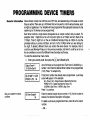
PROGRAMMING
QEVICE
TIMERS
General Information Device timers consist Of an ON time&an OFF time, and selected days of the week in which
they are active. There are up to 20 timers that can be used to control various devices, such
as lights or appliances. Your installer will have programmed the appropriate devices into the
system (up to 16 devices can be programmed).
Each timer controls a single device (designated as an output number) that you select. For
example, timer 1 might be set to turn the porch lights on at 7:OOpm and turn them off at
11:OOpm.Timer 2 might turn on the air conditioner Monday-Friday at 4:30pm to cool the
premises before you arrive at 5:OOpm, and turn it off at 10:OOpm when you are retiring for
the night. If desired, different timers can control the same device. For example, timer 2
could be used Monday-Friday as in the previous example, and timer 3 could be set to turn
the air conditioner on and off at different times Saturday and Sunday.
To enter the device timer menu mode:
1. Enter your security code, then press the
key followed by 83.
❑
Up to 20 timers can be programmed. Each timer is identified by a
number 1-20. Enter the desired timer number to be programmed
(1-20). Press *to accept entry.
06 07:OOP 11 :45P
PORCH LITE 04
I
If that timer number has already been programmed, a summary
screen will appear. In this example:
06= Timer # 04 = Output Device # affected by this timer
PORCH LITE = Output Descriptor for Device # 4
0700PM = Start Time; 11:45PM = Stop Time
Press * to continue.
See your installer for device
numbers.
IE!EKl
Enter the desired output device number (1-1 6). As the number is
entered, the device’s description will appear.
To delete a previously programmed timer, enter 00 as the output
number.
-39-
\
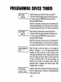
PROGRAMMING
P%Rl
DEVICE TIMERS
Enter the time you want the device turned on using 00:0111:59 format. When the display shows the desired time, press
the * key to move to the AM/PM field. Press any key O-9 to
change the AM/PM indication.
Enter 00:00 if this timer is not being used to turn something ON
for the days selected below. (ex. using one timer to turn lights on
one day and using another timer to turn them off on another day).
Enter the time you want the device turned off using 00:0111:59 format. When the display shows the desired time, press
the * key to move to the AM/PM field. Press any key O-9 to
change the AM/PM indication.
Enter 00:00 if this timer is not being used to turn something OFF
for the days selected below. (ex. using one timer to turn lights on
one day and using another timer to turn them off on another day).
Select the days on which the device is to be activated by
entering 1-7 (Monday = 1). An “X” will appear under that day,
indicating the output for that day is active. Entering a day’s
number again will deactivate that day. Pressing O will turn all days
on/off. The outputs will only be in effect for the days which have
the letter x underneath them. As the week progresses, the
selected days are reset to the deactive state, unless the
permanent option is selected (next screen prompt). When
completed, press * to continue.
Emil
Answering 1 (yes) means the system will continue executing this
timer on a continuous basis. An answer of O means execute each
day’s output only once.
-40-
TESTING THE SYSTEM
(TO BE CONDUCTED WEEKLY)
~
-
Using the
TEST Key
The TEST key puts your system into Test mode, which allows each protection
be checked for proper operation.
1.
Disarm the system and close all protected windows,
displayed.
-
point to
doors, etc. READY should be
TEST
2. Enter your security code and press the
❑ key.
3. The external sounder should sound for 3 seconds and then turn off. If the sounder
does not sound, it maybe due to dialer communication activity. Wait a few minutes
and try again.
If the sounder still does not sound, CALL FOR SERVICE
IMMEDIATELY.
4.
The console will sound a sinale bee~ everv 15 seconds as a reminder that the
system is in Test mode. Each t~me a p;otectiok zone is faulted (opened), the console
should beep three times. If the sounder does not sound, CALL FOR SERVICE
IMMEDIATELY.
Note that no alarm reports will be sent to the central monitoring station
while the svstem is in Test mode.
-41-
TESTING THE SYSTEM
Testing Your
System
1. Open and close each protected door and window in turn and listen for three beeps.
The identification of each faulted protection point should appear on the display.
2. Walk in front of any interior motion detectors (if used) and listen for three beeps as
movement is detected. The identification
of the detector should appear on the
display when it is activated.
3. Follow the manufacturer’s instructions to test all smoke detectors to ensure that all are
functioning properly. The identification of each detector (or the zone number of the
zone assigned to the detector) should appear on the display when each is
activated.
4. When all protection
points have been checked,
there should be no zone
identification numbers displayed. If a problem is experienced with any protection
point (no confirming sounds, no display), CALL FOR SERVICE IMMEDIATELY.
5. Turn off Test mode by entering the security code and pressing the OFF key.
-42-
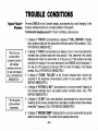
TROUBLE CONDITIONS
The word CHECK on the Console’s display, accompanied by a rapid “beeping” at the
Console, indicates that there is a trouble condition in the system.
To silence the beeping sound for “check” conditions, press any key.
Typical ‘iCheck”
Displays
i
Note that zone
numbers 88-91
represent problems
with wireless
●
receivers, which are
not user serviceable.
CALL FOR SERVICE
IMMEDIATELY.
** Not all systems
employ wireless
transmitters.
1. A display of “CHECK” accompanied by a display of “CALL SERVICE” indicates
that a problem exists with the system that eliminates some of the protection. CALL
FOR SERVICE IMMEDIATELY.
z. A display of “CHECK” accompanied by a display of one or more zone descriptors
indicates that a problem exists with those zone(s)*. First, determine if the zone(s)
displayed are intact and make them so if they are not. If the problem has been
corrected, the display of the zone descriptor(s) and CHECK should disappear. If
not, key an OFF sequence (Code plus OFF) to clear the display. If the display
persists, CALL FOR SERVICE IMMEDIATELY.
FAILURE”
at the Console indicates that a failure has
3. A display of “COMM.
occurred in the telephone communication
portion of your system. CALL FOR
SERVICE IMMEDIATELY.
4. A display of “SYSTEM LO BAT”, accompanied by a once per minute “beeping” at
the Console indicates that a low system battery condition exists. CALL FOR
SERVICE IMMEDIATELY.
5. A display of “LO BAT and a zone descriptor, accompanied by a once per minute
“beeping” at the Console indicates that a low battery condition exists in the wireless
transmitter** displayed. CALL FOR SERVICE IMMEDIATELY.
6. A display of “MODEM COMM” indicates that the control is on-line with the central
station’s remote computer. The control will not operate while on-line.
-43-
TROUBLE
Power
Failure
Non-Alpha
Console
Displays
CONDITIONS
If the POWER
indicator is off, operating power for the system has stopped and is
inoperative. CALL FOR SERVICE IMMEDIATELY.
If the POWER indicator is on, but
the message “AC LOSS” is displayed, the Console is operating on battery power
only. If only some lights are out on the premises, check circuit breakers and fuses and
reset or replace as necessary. CALL FOR SERVICE IMMEDIATELY
if AC power
cannot be restored.
The following displays will appear on non-alpha
condition (previously described) is present.
consoles when the associated
trouble
97= CALL SERVICE
FC = COMM FAILURE
BAT = SYSTEM LO BAT (if no zone number) or LO BAT (if zone number shows)
CC= MODEM COMM
NO AC = AC LOSS
SERVICING
lNFORIMATION
Your local Ademco dealer is the person best qualified to service your alarm system.
Arranging some kind of regular service program with him is advisable.
Your local Ademco dealer is
Name:
Address:
I Phone:
-44-
FIRE
General
In Case Of Fire
Alarm
Silencing
A Fire
Alarm
ALARM
SYSTEM
(IF
INSTALLED)
Your fire alarm system (if installed) is on 24 hours a day, providing continuous
protection. In the event of an emergency, the installed smoke and heat detectors will
automatically send signals to your Control/Communicator,
triggering a loud, interrupted
sound from the Console.
An interrupted sound will also be produced by optional
exterior sounders. A FIRE message will appear at your Console and remain on until you
silence the alarm.
1. Should you become aware of a fire emergency before your detectors sense the
problem, go to your nearest Console and manually initiate an alarm by pressing the
panic key pair assigned as FIRE emergency (if programmed by the installer) and
hold down for at least 2 seconds.
2. Evacuate all occupants from the premises.
3. If flames and/or smoke are present, leave the premises and notify your local Fire
Department immediately.
4. If no flames or smoke are apparent, investigate the cause of the alarm. The zone
descriptor of the zone(s) in an alarm condition will appear at the Console.
1.
2.
3.
4.
Silence the alarm by entering your code and pressing the OFF key. To clear the
display, enter your code and press the OFF key again.
If the Console does not indicate a READY condition after the second OFF sequence,
press the READY key to display the zone(s) that are faulted. Be sure to check
that smoke detectors are not responding to smoke or heat producing objects in their
vicinity. Should this be the case, eliminate the source of heat or smoke.
If this does not remedy the problem, there may still be smoke in the detector. Clear it
by fanning the detector for about 30 seconds.
When the problem has been corrected, clear the display by entering your code and
pressing the OFF key.
-45-
NATIONAL
FIRE
PROTECTION
RECOMMENDA71ONS
ON
SMOKE
ASSN.
DETECTORS
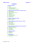
With regard to the number and placement of smoke/heat detectors, we subscribe to the
recommendations
contained in the National Fire Protection Association’s Standard #74
noted below.
Early warning fire detection is best achieved by the installation of fire detection
equipment in all rooms and areas of the household as follows: A smoke detector installed
outside of each separate sleeping area, in the immediate vicinity of the bedrooms and on
each additional story of the family living unit, including basements and excluding crawl
spaces and unfinished attics.
In addition, it is recommended that the householder consider the use of heat or smoke
detectors in the living room, dining room, bedroom(s), kitchen, hallway(s), attic, furnace
room, utility and storage rooms, basements and attached garages.
M&&d
“:wM
■
Smoke Detectorsfor Minimum Protection
~
Smoke Detectorsfor AdditionalProtection
A Heat-Activated Detectors
BASEMENT
I
-46-
EMERGENCY
i I1
I 71
AI
\
m
❑
BACK
❑
o
❑
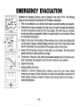
EVACUATION
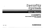
Establish and regularly practice a plan of escape in the event of fire. The following
steps are recomm-ended by the Natio”nal Fire Protection Association:
1. Plan on your detector or your interior and/or exterior sounders warning all occupants.
2. Determine two means of escape from each room. One path of escape should lead to
the door that permits normal exit from the building. The other may be a window,
should your path be unpassable. Station an escape ladder at such windows if there
is a long drop to the ground.
3. Sketch a floor plan of the building. Show windows, doors, stairs and rooftops that
can be used to escape. Indicate escape routes for each room. Keep these routes
free from obstruction and post copies of the escape routes in every room.
4. Assure that all bedroom doors are shut while you are asleep. This will prevent
deadly smoke from entering while you escape.
5. Try the door. If the door is hot, check your alternate escape route. If the door is cool,
open it cautiously. Be prepared to slam the door if smoke or heat rushes in.
6. Crawl in the smoke.
7. Escape quickly; don’t panic.
8. Establish a common meeting place outdoors, away from your house, where
everyone can meet and then take steps to contact the authorities and account for
those missing. Choose someone to assure that nobody returns to the house —
many die going back.
0
~~
FRONT
-47-
MAINTAINING YOUR SYSTEM
Taking Care of
Your System
Replacing
Batteries in
Wireless
Sensors
The components of your security system are designed to be as free of maintenance as
possible. However, there are some things you can do to make sure that your system is
in reliable working condition.
1. Test your system weekly.
2. Test the system after any alarm occurs (see TEST/IVG
THE SYSTEM).
Each wireless sensor in your system has a 9-volt battery. The system detects a low
battery in any wireless sensor, including smoke detectors, the optional personal
emergency transmitter, and the optional portable wireless keypad. (A low battery in a
portable wireless keypad is detected as soon as one of its keys is pressed, and the
console will display 00.)
Alkaline batteries provide a minimum of 1 year of operation, and in most units and
applications,
environment
E!EEEl
sensor
or low
actual
provide
2–4
years
of service.
Actual
battery
life will depend
on the
in which the sensor is used, the number of signals that the transmitter in the
has had to send, and the specific type of sensor. Factors such as humidity, high
temperatures
or large swings in temperature,
may all lead to the reduction of
battery life in an installation.
have a low battery in a wireless sensor, a low battery message is
If you
displayed
on the console.
In addition, a battery-operated
smoke detector with a low battery also emits a single
“chirp” sound once approximately every 20-30 seconds, identifying itself as the smoke
detector with the weak battery. If you do not replace a smoke detector’s low battery,
the smoke detector may sound continuously, as if there were a fire alarm.
Note:
The low battery message comes on as a warning that battery replacement
in indicated sensor(s) is due within 30 days. In the meantime, the sensor(s) causing the
low battery indication is still fully operational.
Impc?rtant: Use only batteries recommended by your installer as replacement.
-48-
MAINTAINING YOUR SYSTEM
The console’s warning tones can be silenced by performing an OFF sequence (code
plus OFF key), but the Console’s low battery message display will remain on as a
reminder that you have a low battery condition in one or more of your sensors. When
you replace the weak battery with a fresh one, the sensor will send a “good battery”
signal to the control as soon as the sensor is activated (opening/closing
of door,
window, etc.), causing the low battery display to turn off. If the sensor is not activated,
the display WIII automatically clear within approximately 1 hour.
Silencing Low
Battery Warning
Tones at the
Console
Routine Care
●
●
●
Treat the components
of your security system as you would any other electrical
equipment. Do not slam sensor-protected doors or windows.
Keep dust from accumulating on the console and all protective sensors, particularly on
motion sensors and smoke detectors.
The console and sensors should be cleaned carefully with a dry soft cloth. Do not
spray water or any other fluid on the units.
QUICK
SYSTEM
FUNCTION
PROCEDURE
Check Zones
Display All
Descriptors
Arm System
Press [*]
Press and hold [x]
for 5 seconds
Enter code
Press arming key desired
(AWAY, STAY, INSTANT,
MAXIMUM)
Enter code
Press OFF [1]
Enter code
Press BYPASS [6]
Enter zone numbers to be
bypassed (use 2-digit entries)
Enter code
Press BYPASS [6]
Press [#]
Enter code
Press CHIME [9]
Enter code
Press TEST [5]
Press and hold [0] for at least
5 seconds.
Enter user’s code
Press [*] + [*]
Disarm System
Bypass zones
Quick Bypass
Chime Mode
Test Mode
View Messages
View User
Capabilities
GUIDE
TO
~UNCTIONS
COMMENTS
To view faulted zones when system not ready.
Displays all alpha descriptors programmed by installer.
Arms system in mode selected.
Disarms system and silences alarms.
Bypassed zones are unprotected and will not
cause an alarm if violated.
Bypasses all faulted zones automatically.
Console will sound if doors
or windows are violated while system disarmed.
Sounds alarm sounder and allows sensors to be tested.
Message from central station will appear,
Displays partitions & authority
levels assigned to the user.
–50-
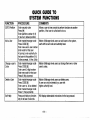
QUICK GUIDE TO
SYSTEM FUNCTIONS
FUNCTION
PROCEDURE
COMMENTS
GOTO Partition
Enter security code
Allows a user at one console to perform functions in another
Press [*]
Enter partition number (1-8)
O returns to default partition
Enter masterlmanager code
Press CODE [8]
Enter new user’s user number
Enter code for that user
At prompt, enter authority for
that user in this partition (1-5)
Follow prompts, 1=Yes, O=NO
Enter master/manager code
Press CODE [8]
Enter user’s 2-digit number
Enter new code for that user
Press O (No) at prompt.
Enter master/manager code
Press CODE [8]
Enter user no. to be deleted
Enter master/manager code
Press 1 (Yes) at prompt.
Press and hold any function
key for at least 5 seconds.
partition, if that user is authorized to do so.
Add a User
Change a user’s
Code
Delete a User
Self-Help
Master & Manager level users can add users to the system,
each with its own code and authority level.
Master & Manager level users can change their own or other
users’ codes.
Master & Manager level users can delete users.
A user can only be deleted by a user with
higher authority level.
Will display abbreviated instructions for the key pressed.
-51-
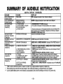
SUMMARY
OF AUDIBLE
(ALPHA
SOUND
t-k
D*
Console & External
LOUD CON~
Consoie & External
(not repeated)
Console only
I CAUSE
~~tiLAHY/AU=
EMERGENCY ALARM
a. sY~ARM
b. SYSTEM ARMING AITEMPT
WITH AN OPEN ZONE.
c. BYPASS VERIFY
~~ODt
NOTIFICATION
DISPLAY CONSOLES)
I DISPLAY
descrmtor of zone
t ISdmlaved:
.
ALA ~e
m alarm IS dmlaved.
m alarm ISalso displayed.
a. DISA~
ARM IS dsplayed.
b, The number and descriptor of the open protectionzone is displayed.
c. Numbers and descriptorsof the bypassad protectionzones are displayed (One
beep is heard for each zone d~played). Subsequently, the followingis displayed:
DISARMED BYPASS Ready to Arm
Opened L one identificationsWIIIappear.
(once every 15 seconds)
Console only
SHO_EEPS
Console only
Rtt SHOli I BkkPS
Console only
l-iA~
Console only
SLOW 13kt14NG
Console only
,.
ARM AWAY OR MAXIMUM
a. A1-tM~!ANT
b. ZONE OPENED WHILE SYSTEM
IS IN CHIME MODE,
c. ENTRY WARNING*’
a. 1 tiOUBLk
b. AC POWER LOSS ALERV
c. MEMORY OF ALARM
a. kN I HY DELAY
b. EXIT DELAY WARNING
(if programmed)
A~A
Y or ARtotti MAIS displayed. I-ied ARME u Indicator IS
lit.
a, ARMtD ~~ONe
BYPASSkD
is displayed. Red ARMED indicator is ~
b. CHIME displayed, descriptor of open protection zone will be displayed if the [x]
ke is pressed.
c. 6 ISARM SYSTEM OR ALARM WILL OCCUR is displayed,
a. CHtCK d isplayed, Descriptor of troubled protection zone is displayed.
b. AC LOSS displayed (may alternate with other displays that maybe present).
delay time without disarming causes alarm.
~o\RMED AWAY or ARMED MAXIMUM is displayed along with You May Exit
*
If bell is used as external sounder, fire alarm is pulsed ring; burglary/audible emergency is steady ring.
**
Entry warning may consist of three short beeps or slow continuous beeping, as programmed by your installer.
*V* Loss of system battery power is not indicated or annunciated by the console (warnings are for loss of AC power only).
–52-
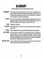
GLOSSARY
The following glossary of terms are used throughout the manual.
ARM/DISARM:
KEYPAD:
ZONE:
PARTITION:
BYPASS:
DELAY
ZONE:
DAY/NIGHT
ZONE:
“Armed” simply means that the burglary portion of your system is turned ON and is in a
state of readiness. “Disarmed” means that the burglary system is turned OFF, and must
be rearmed to become operational, However, even in a “disarmed” state, “emergency”
and “fire” portions of your system are still operational.
This is the area on your Console containing numbered pushbuttons similar to those on
telephones or calculators. These keys control the arming or disarming of the system, and
petform other functions which were previously described in this manual.
A specific area of protection.
An independent group of zones that can be armed and disarmed without affecting other
zones or users.
To disarm a specific area of burglary protection while leaving other areas operational.
An area of protection containing doors most frequently used to enter or exit (typically, a
front door, back door, or door from the garage into the building). The delay zone allows
sufficient time for authorized entry or exit without causing an alarm. Consult your installer
for the entry and exit delay times that have been set for your system during installation
and record them on the separate sheet provided in this manual.
An area of protection whose violation causes a trouble indication during the disarmed
(DAY) mode and an alarm during the armed (NIGHT) mode.
-53-
UL
“FEDERAL
NOTICE:
COMMUNICATIONS
is a “GRADE
COMMISSION
This
A“
svstem.
(FCC)
This equipment has been tested to FCC requirements and has been found acceptable
statement for your information:
Part
for use.
15
STATEMENT”
The FCC requires the following
This equipment generates and uses radio frequency energy and if not installed and used properly, that is, in strict accordance with the
manufacturer’s instructions, may cause interference to radio and television reception. It has been type tested and found to comply with
the limits for a Class B computing device in accordance with the specifications in Part 15 of FCC Rules, which are designed to provide
reasonable protection against such interference in a residential installation. However, there is no guarantee that interference will not
occur in a particular installation. If this equipment does cause interference to radio or television reception, which can be determined by
turning the equipment off and on, the user is encouraged to try to correct the interference by one or more of the following measures:
“
If using an indoor antenna, have a quality outdoor antenna installed.
●
●
Reorient the .ceceiyin~,antenna
... . . .., until interference is reduced or eliminated
Move the receiver away from the control/communicator.
“
Move the antenna leads away from any wire runs to the controllcommunicator.
“ Plug the control/communicator into a different outlet so that it and the receiver are on different branch circuits.
If necessary, the user should consult the dealer or an experienced radio/television technician for additional suggestions.
The user or installer may find the following booklet prepared by the Federal Communications Commission helpful: “Interference
Handbook
This booklet is available from the U.S. Government Printing Office, Washington, DC 20402.
The user shall not make any changes or modifications to the equipment unless authorized by the Installation Instructions or User’s
Manual. Unauthorized changes or modifications could void the user’s authority to operate the equipment.
PROBLEMS
IN THE EVENT OF TELEPHONE OPERATIONAL
In the event of telephone operational problems, disconnect the control by removing the plug from the RJ31 X (CA38A in Canada)
tele~hone wall iack. We recommend that vour certified installer demonstrate disconnecting the Dhones on installation of the svstem. Do
not ‘disconnect ~he ~hone connection inside the control/communicator. Doina so will resui{ in th’e loss of vour ~hone lines. If tie reaular
phone works correctly after the controlicommunicator has been disconnec~ed from the phone lines, th’e co~trollcommunicator h>s a
problem and should be returned for repair. If upon disconnection of the control/communicator, there is still a problem on the line, notify
the telephone company that they have a problem and request prompt repair service. The user may not under any circumstances (in or
out of warranty) attempt any service or repairs to the system. It must be returned to the factory or an authorized service agency for all
repairs.
-54-
“FEDERAL
COMMUNICATIONS
COMMISSION
(FCC)
Part
68
NOTICE
This equipment complies with Part 68 of the FCC rules. On the front cover of this equipment is a label that contains, among
other information, the FCC registration number and ringer equivalence number (REN) for this equipment. If requested, this
information must be provided to the telephone company.
This equipment uses the following jacks:
An RJ31 X is used to connect this equipment to the telephone network.
The REN is used to determine the quantity of devices which may be connected to the telephone line. Excessive RENs on
the telephone line may result in the devices not ringing in response to an incoming call. In most, but not all areas, the sum
of the RENs should not exceed five (5.0). To be certain of the number of devices that may be connected to the line, as
determined by the total RENs, contact the telephone company to determine the maximum REN for the calling area.
If this equipment causes harm to the telephone network, the telephone company will notify you in advance that temporary
discontinuance of service may be required. If advance notice is not practical, the telephone company will notify the
customer as soon as possible. Also, you will be advised of your right to file a complaint with the FCC if you believe
necessary.
The telephone company may make changes in its facilities, equipment, operations, or procedures that could affect the
operation of the equipment. If this happens, the telephone company will provide advance notice in order for you to make
the necessa~ modifications in order to maintain uninterrupted service.
If trouble is experienced with this equipment, please contact the manufacturer for repair and warranty information. If the
trouble is causing harm to the telephone network, the telephone company may request you remove the equipment from
the network until the problem is resolved.
There are no user serviceable components in this product, and all necessary repairs must be made by the manufacturer.
Other repair methods may invalidate the FCC registration on this product,
This equipment cannot be used on telephone company-provided coin service, Connection to Party Line Service is
subject to state tariffs.
This equipment is hearing-aid compatible.
When programming or making test calls to an emergency number, briefly explain to the dispatcher the reason for the call.
Perform such activities in the off-peak hours; such as early morning or late evening.
-55–
I
CANADIAN
NOTICE
DEPARTMENT
OF COMMUNICATIONS
[DOC)
. STATEMENT
.
The Canadian Department of Communications label identifies certified
equipment. This cefilfication means that the equipment meets certain
telecommunications network protective, operational and safety requirements.
The Depamnent does not guarantee the equipment will operate to the uset%
satisfaction.
Before installing this equipment, users should ensure that it is permissible to
be connected to the facilities of the local telecommunications company. The
equipment must also be installed using an acceptable method of connection. In
some cases, the company’s inside wiring associated with a single line
individual service may be extended by means of certified connector assembly
(telephone extension cord). The customer should be aware that compliance
with the above conditions may not prevent degradation of service in some
situations.
Repairs to certified equipment should be made by an authorized Canadian
maintenance facility designated by the supplier. Any repairs or alterations
made by the user to this equipment, or equipment malfunctions, may give the
telecommunications company cause to request the user to disconnect the
equipment,
Users should ensure for their own protection that the electrical ground
connections of the power utility, telephone lines and internal metallic water
pipe system, if present, are connected together. This precaution may be
particularly important in rural areas.
Caution: User should not attempt to make such connections themselves, but
should contact the appropriate electric inspection authority, or electrician, as
appropriate.
n
Th
r (LN) assigned to each terminal device denotes the
~~~n~$!:~~fal
load tobe:onnectedtoatelephonelcopwhich
is used
e dewce, to prevent overfoadmg. The terrmnabon on a loop may consist of
any combination of devices subject only to the requirement that the total of the
Load Numbers of all the devices doas not exceed 100.
-56-
AVIS
LWiquette du ministere des Communications du Canada identifie Ie materiel
homologue. Cette etiquette certifie que Ie materiel est corrforme a certaines
normes de protection, d’exploitation et de securite des rt%eaux de
t~ldcommunicafions. Le ministbre n’assure toutefois ,,
oas oue Ie mak$riel
forvctionneraa la satisfaction de I’ufilisateur.
Avant dlnstailer ce materiel, I’utilisateur doit s’assurer qu’il est permis de Ie
raccorder aux installations de I’entreprise locale de telecommunications. Le
materiel doit egalement 6tre installe en suivant une methode acceptee de
raccordement. Dans cerfains cas, 18sfils interieursde I’entrepriseutilises
pourun sem”ce individual ala Iigne unique peuvent ~tre prolonges au moyen
dun dispositifhomologue de raccordement (cordon prolongateur tdephonique
interne). L’abonne ne doit pas oublier qu’il est possibie que la conformit6 aux
condtions enonc6es ci-dessus n’empechet pas la degradation du service clans
certairres situations. Actuellement, [es entreprises de telecommunications ne
permeffent pas que loonraccorde Ieur materiel aux prises d’abonnes, sauf
clans Ies cas precis pr6vus par Ies tanfs particuliers de ces entreprises.
Les reparations du materiel homologue doivent 6tre effectuees pas un centre
d’entretien canadien autorise designe par Ie fournisseur. La compagnie de
telecommunications peut demander a I’utilisateurde d6brancher un appareil a
la suite de reparations ou de modifications effectuees par I’utilisateur ou a
cause de mauvais fonctionnement.
Pour se propre protection, I’utilisateur doit s’sssurer que tous Ies fils de mise
en terre de la source d’6nergie electnque, des Iignes telephoniques de reseau
de conduites d’eau s’ily en a, aoient raccordes ensemble. Cette precaution est
parficulierement importanceclans Ies regions mrales.
Avertiseemenk
L’utilisateur ne doit pas tenter de faire ces raccordements
lui-m~me; il doit avoir recours A un service d’inspection des installations
electriques, ou & un electrician, selon Ie cas.
,.
dice de charae (IC) assigne a chaque dispositif terminal pour Aviter toute
surcharge indiqu= Ie p6urcefita~e de la charge totale qui peut ?4re raccorde a
un circuit telephonique boucle utilise par ce dispositif. La terminaison du
circuit boucle peut Gtre constitute de niimporte quelle combinaison de
dispositifa, pourvu que la somme des indices de charge de I’ensemble des
dispositifsne d6passe pas 100.
WARNING!
THE
LIMITATIONS
OF THIS
ALARM
SYSTEM
Nhile this system is an advanced design security system, it does not offer guaranteed protection against burglary or fire or other
>mergency. Any alarm system, whether commercial or residential, is subject to compromise or failure to warn for a variety of reasons.
‘or example:
~ Intruders may gain access through unprotected openings or have the technical sophistication to bypass an alarm sensor or
disconnect an alarm warning device.
I Intrusion detectors (e.g. passive infrared detectors), smoke detectors, and many other sensing devices will not work without power.
Battery operated devices will not work without batteries, with dead batteries, or if the batteries are not put in properly. Devices
powered solely by AC will not work if their AC power supply is cut off for any reason, however briefly.
I Signals sent by wireless transmitters maybe blocked or reflected by metal before they reach the alarm receiver. Even if the signal
path has been recently checked during a weekly test, blockage can occur if a metal object is moved into the path.
~ A user may not be able to reach a panic or emergency button quickly enough.
~ While smoke detectors have played a key role in reducing residential fire deaths in the United States, they may not activate 01
provide early warning for a variety of reasons in as many as 35% of all fires, according to data published by the Federal Emergency
Management Agency. Some of the reasons smoke detectors used in conjunction with this System may not work are as follows.
Smoke detectors may have been improperly installed and positioned. Smoke detectors may not sense fires that start where smoke
cannot reach the detectors, such as in chimneys, in walls, or roofs, or on the other side of closed doors. Smoke detectors also may
not sense a fire on another level of a residence or building. A second floor detector, for example, may not sense a first floor of
basement fire. Moreover, smoke detectors have sensing limitations, No smoke detector can sense every kind of fire every time. In
general, detectors may not always warn about fires caused by carelessness and safety hazards like smoking in bed, violent
explosions, escaping gas, improper storage of flammable materials, overloaded electrical circuits, children playing with matches, or
arson. Depending upon the nature of the fire and/or the locations of the smoke detectors, the detector, even if it operates as
anticipated, may not provide sufficient warning to allow all occupants to escape in time to prevent injury or death.
I Passive Infrared Motion Detectors can only detect intrusion within the designed ranges as diagramed
in their installation manual.
Passive Infrared Detectors do not provide volumetric area protection. They do create multiple beams of protection, and intrusion can
only be detected in unobstructed areas covered by those beams. They cannot detect motion or intrusion that takes place behina
walls, ceilings, floors, closed doors, glass partitions, glass doors, or windows. Mechanical tampering, masking, painting or spraying
of any material on the mirrors, windows or any part of the optical system can reduce their detection ability. Passive Infrarec
Detectors sense changes in temperature; however, as the ambient temperature of protected area approaches the temperature range
of 90° to 1050F, the detection performance can decrease.
-57-
I
VVAtf NINUi!
THE
LIMITATIONS
OF THIS
(continued)
~●
ALARM
SYSTEM
Alarm warning devices such as sirens, bells or horns may not alert people or wake up sleepers if they are located on the other side of
closed or partly open doors. If warning devices sound on a different level of the residence from the bedrooms, then they are less
likely to waken or alert people inside the bedrooms. Even persons who are awake may not hear the warning if the alarm is muffled
I from a stereo, radio, air conditioner or other appliance, or by passing traffic. Finally, alarm warning devices, however loud, may not
~ warn hearing-impaired people or waken deep sleepers.
● Telephone lines needed to transmit alarm signals from a premises to a central monitoring station may be out of service or temporarily
out of service. Telephone lines are also subject to compromise by sophisticated intruders.
I* Even if the system responds to the emergency as intended, however, occupants may have insufficient time to protect themselves
from the emergency situation. In the case of a monitored alarm system, authorities may not respond appropriately.
● This equipment, like other electrical devices, is subject to component failure. Even though this equipment is designed to last as long
as 10 years, the electronic components could fail at any time.
The most common cause of an alarm system not functioning when an intrusion or fire occurs is inadequate maintenance. This alarm
system should be tested weekly to make sure all sensors and transmitters are working properly.
installing an alarm system may make one eligible for lower insurance rates, but an alarm system is not a substitute for insurance.
Homeowners, property owners and renters should continue to act prudently in protecting themselves and continue to insure their lives
I and property.
I We continue to develop new and improved protection devices. Users of alarm systems owe it to themselves
and their loved ones to
learn about these developments.
-58-
OWNER’S
INSURANCE
PREMIUM
CREDIT
REQUEST
This form should be completed and forwarded to your homeowner’s insurance carrier for possible premium credit.
A. GENERAL INFORMATION:
,nsured’sName and Address:
Mcy No.:
hsuranceCcmpany
ADEMCO’S
VISTA-50
Type of Alarm:
❑
Other
m
Burglary
❑
Fire
Serviced by
Installedby
Name
Name
Address
Address
B. NOTIFIES (Insert B = Burglary, F = Fire)
FireDe@
Polii Dept.
LocalSoundiig Device
Central Station a
Name
Ackkesl
!+mrle:
C. POWERED
D.
TESTING:
BY: A.C. With Rechargeable Power Supply
❑
Quarterly
Both
❑
Monthly
❑
Weekly
❑
continuedon other aide
-59-
Other
E. SMOKE
❑
❑
DETECTOR
LOCATIONS
Furnace Room
Basement
F. BURGLARY
m FrontDoor
DETECTING
❑
❑
DEVICE
Basement Door
❑
All windows
lst Floor Windows
D
All Accessible Openings,lncluding
PERTINENT
LOCATIONS:
D
❑
G. ADDITIONAL
Kitchen
Living Room
❑
❑
❑
❑
Dining Room
❑
❑
Rear Door
❑
Bedrooms
Interior locations
Swlights, Air Conditioners and Vents
INFORMATION:
Date
siglaiure:
–60-
Attic
Hall
All Exterior Doors
INDEX
A
AC .........................................9
AC LOSS .. .. ... ..... . .. ... .. ... .. .....44
Access Another Partition ,. .. .....19
access door . ... .... .... .... ...... ....33
Adda User .. .... .. .. ... ..... ... .. ... . . 16
Ademcodealer . ..... ... .. ... .. ..... . . 44
alarm ...................................5.9
ALPHA ..... .. ... . ..... ... .... ... .. ... ....8
Alpha consoles .... ... ... .. ... .. ... ....8
armed .....................................4
Audible Emergency .. . .... ..... . ....32
Authority levels .. .. ..... . .. 13.14.15
Away ....................4.9 .19.26.29
B
BAT . ... ...>... . ... .... ..... .... ......9. 44
burglary ... . .. ... ... ... .. ... .. . .... . ... ...3
burglary protection ... .................4
BYPASS .,, ... .. ... .. ..... ... ... .. ... ....9
bypass zones .. .. ..... .. ... . .... .....22
BYPASSING ..........................22
c
CALL SERVICE .. ... .... ... ..... .....43
cc . .. .. .... .... . ....... ... .. ... . ..... .. .. 44
ChangeaUser’sCode
. .. .. .... ....18
CHECK ... .. ... .. ...... ..... ... .. ....9. 43
CHIME ............................4.9.3o
closing time ,. .. ...... .. ... ... ... .. ....35
CODE ........................ ...........16
COMM. FAILURE ..,, ... . ... ..... ....43
D
Delaying the Closing Time .........35
Delete a User .. .. . .. ... ..... ...... .... 18
descriptors ......... ...... ...... ....... 21
Device Timers . .. ... . .. .. . .... . ....6.39
disarm ... . .... ...... ..... ... .. .. .... .... 28
Duress .. .. ... ... ... .. ... .. . .. .. .... ....14
Duress Code ..........................13
1, K
Instant .. ... ... .. .. . .... .....4.9. 19,25
keyswitch ... ...... .... .... .. .. .... ....29
L
LO BAT .................................43
low battery ... .. .. ...... .. ...... .. .....48
Low BatteryWarning .. ... ... .. .....49
E
M
emergency ,. ... .. ... ...... ..... .. .......3
EMERGENCYEVACUATION
,....47
Entry Delay . ..... ... ... ... ....... . ....12
Entry/Exit ., . ... .. ... ..... . .... ... ... ....4
exit delay .. .. ... ... .. ... .. ... ... ... ....12
Exit User Edit Mode .................15
maintenance ..........................48
Manager .... .. .... ..... ... ... .. . ... ....14
Master ..................................14
Maximum .. .. ...... .. ..... . ....4.19.27
Memory of Alarm ..................5.28
MODEMCOMM . ....... .... .. ... . ....43
F
FC .. ..... .. ... .. ... .. . .. .. . ... .. ... ... .... 44
fire ..................... .......3,9,32,45
fire emergency .. ... ... .. . .. .. .... ....45
fire protection . .. . .. ... ..... ..... . ......5
FIXED-WORD ... . .. ... .. ... .. .... ......8
Fixed-Word Console Displays ......9
Fixed-Word consoles ................. 8
N
NOAC .... ....... ..... ...... .......9. 44
NOTREADY ... ..... .. ....<. .. .....9. 20
G
GlobalArming . .. . ..... ..... ..... . ....19
GOTO . .. ... ..... .. ... ..... . .......17. 19
GOTO command .......................6
consoles .................................8
-61-
0
OFF . .. ...... .. ... ... .... .... .. 19,28,45
OPENZONES ., .. ....... ...... .. .....20
Open/Close Schedules ,... . .. .....36
Operator A ... .. ........ .. ... ... ... ....14
Operator B ... ..... .. ..... . ..... .......14
Operator C ... .. .. ...... .. ..... ... . ....14
INDEX
P
T
Panic Keys ............................32
Partitioned Security System . . .. ...3
partitioned system . .. .... . . ... .. . .. ...3
Personal Emergency .. ... . .. ... . ...32
Phone Access ... .. ... . .. ... . .. .. .. ....7
plan of escape .. . .. .. .. .. .. .. .. . .. ...47
Power ..... ..............................44
Temporary schedules . . . .. . ...36.37
Temporary users .. .. . . .. . .. .. . . .. ...16
TEST key . .. . . . ... . . ... . . .. . .. .. . . .. ...41
time window .. . .. ... . ... . . .. .. . .. . .. ...36
trouble condition .....................43
Q
Quick Arming ................... ...... 13
Quick Bypass ... ..... ................23
u
User Edit Mode ....................... 15
user numbers
. . . . . . . . .. . . . . . . . . . . . . . . . 13
user’s instructions .. . . ... . ... . ... . . ...7
v, w, z
R
READY .. . . . .. . . .. .. .. . .. ..9. 20.30.45
READY key ... . .. .. . .. ... . .. .. ...20.21
Replacing Batteries ... ..............48
voice module .. . . ... . . ... . ... . . ....7.34
wireless sensor .. . .. . .. . .. . .. . . .. . ...48
ZONE BYPASSED . .. . . .. . . .. . .. ....24
zone descriptors .. . . .. . .. .. . ... . . ...21
s
schedules . . .. .. .. .. . .. .. .. .. ... . ...6.35
security code .........................13
SECURITY CODES ,.. .. . ... . . .. ....13
sensing ctevices ... .. ... .. . .. .. .. . .....4
Silence thealarm ... . .. .. . .. . .. .. ....45
Silent Emergency . .. .. .. .. .. ... . . ...32
smoke detectors .. . ... . .. .. .. . .. ....42
Stay ......... ....... .....4.9 .19.24.29
SYSTEM LO BAT ... . . ... . .. . .. .. ....43
-62-
I
General Information
To Dispiay The Event Log
The system has the ability to record various events in a
historv Ioa wherein each event is recorded in one of
five c~teg~ries (listed below), with the time and date of
its occurrence. The Event Log holds up to 224 events,
with the oldest event being replaced by the logging of
any new event after the log is full. Using an alpha
console, the Event Log can be viewed one category at
a time, or can display all events, regardless of category
(ALL EVENT LOG). The system also allows selection
of displaying the COMPLETE log, or only those events
occurring since the last installer service (RECENT). In
addition, events in the other partitions can be viewed
by users authorized to access those partitions. Note
that events are displayed in chronological order, from
most recent to oldest.
1.
Enter CODE + [#] + [6] + [0]
2.
Seiect the display mode.
RECENT: Displays only those events occurring since last
installer service.
COMPLETE:
Displays complete event log (up to 224
events).
Press the desired key, O or 1.
~
3.
the partition, O-8.
Enter the partition number for the partition whose events
are to be displayed.
Select
Entering O (NO) will display all partitions’ events.
~
Side A Part
of
N5943-4V1
OVER
EVENT LOGGING
4.
PROCEDURES
Use the [3] & [1] keys (for next and previous
categories respectively) to display the categories of
events.
Press [8] to select a category and display the
first event. Press [8] again for each subsequent
event.
Shows burglary alarm occurred in zone 3 (C03) of
partition 1 (Pl ), at 12:02AM on January 1.
~
:%:::;’
After the last event has been displayed, the END
OF EVENT LOG message appeara for a few seconds,
then the system
RECENT/COMPLETE
step 2).
5.
automatically
displays
the
mode select screen again (see
To EXIT the Event Log:
Press [*] at any time.
(continued)
EmKl
::~=~:~”
ALARM EVENT LOG
Displays time and date for zones that have either caused
an alarm or have been restored in the selected partition.
CHECK EVENT LOG
Displays time and date for zones that have caused a
trouble or supervisory condition in the selected partition.
BYPASS EVENT LOG
Displays time and date
bypassed in the partition.
for zones
that
have
been
OPEN EVENT
LOG
Displays time, date and user number for each arming and
disarming of the system for the partition selected.
SYSTEM
EVENT
LOG
Displays time and date for system problems, such as AC
Loss, low battery, etc., regardless of partition.
ALL EVENT LOG
Displays all categories of events in chronological order.
See your
information
Side B
Installer
for additional
concerning
the event
log.
ADEMCO
ONE
YEAR
LIMITED
WARRANTY
Alarm Device Manufacturing Company, a Division of Pittway Corporation, and its divisions, subsidiaries and affiliates (‘Seller”), 165
Eileen Way, Syosset, New York 11791, warrants its security equipment (the “product”) to be free from defects in materials and
workmanship for one year from date of original purchase, under normal use and service. Seller’s obligation is limited to repairing or
replacing, at its option, free of charge for parts, labor, or transportation,
any product proven to be defective in materials of
workmanship under normal use and service. Seller shall have no obligation under this warranty or otherwise if the product is altered or
improperly repaired or serviced by anyone other than the Seller. In case of defect, contact the security professional who installed and
maintains your security equipment or the Seller for product repair.
This one year Limited Warranty is in lieu of all other express warranties, obligations or liabilities. THERE ARE NO EXPRESS
WARRANTIES, WHICH EXTEND BEYOND THE FACE HEREOF. ANY IMPLIED WARRANTIES,
OBLIGATIONS OR LIABILITIES MADE
BY SELLER IN CONNECTION WITH THIS PRODUCT, INCLUDING ANY IMPLIED WARRANTY OF MERCHANTABILITY,
OR FITNESS
FOR A PARTICULAR PURPOSE OR OTHERWISE, ARE LIMITED IN DURATION TO A PERIOD OF ONE YEAR FROM THE DATE OF
ORIGINAL PURCHASE.
ANY ACTION FOR BREACH OF ANY WARRANTY,
INCLUDING BUT NOT LIMITED TO ANY IMPLIED
WARRANTY OF MERCHANTABILITY,
MUST BE BROUGHT WITHIN 12 MONTHS FROM DATE OF ORIGINAL PURCHASE. IN NO CASE
SHALL SELLER BE LIABLE TO ANYONE FOR ANY CONSEQUENTIAL
OR INCIDENTAL DAMAGES FOR BREACH OF THIS OR ANY
OTHER WARRANTY, EXPRESS OR IMPLIED, OR UPON ANY OTHER BASIS OF LIABILITY WHATSOEVER,
EVEN IF THE LOSS OR
DAMAGE IS CAUSED BY THE SELLER’S OWN NEGLIGENCE OR FAULT. Some states do not allow limitation on how long an implied
warranty lasts or the exclusion or limitation of incidental or consequential damages, so the above limitation or exclusion may not apply
to you.
Seller does not represent that the product may not be compromised or circumvented; that the product will prevent any personal injury or
property loss by burglary, robbery, fire or otherwise; or that the product will in all cases provide adequate warning or protection. Buyer
understands that a properly installed and maintained alarm may only reduce the risk of a burglary, robbery, fire or other events
occurring without providing an alarm, but it is not insurance or a guarantee that such will not occur or that there will be no personal injury
or property loss as a result. CONSEQUENTLY,
SELLER SHALL HAVE NO LIABILITY FOR ANY PERSONAL INJURY, PROPERTY
DAMAGE OR OTHER LOSS BASED ON A CLAIM THE PRODUCT FAILED TO GIVE WARNING. HOWEVER, IF SELLER IS HELD LIABLE, WHETHER DIRECTLY OR INDIRECTLY,
FOR ANY LOSS OR DAMAGE ARISING UNDER THIS LIMITED WARRANTY OR
OTHERWISE,
REGARDLESS
OF CAUSE OR ORIGIN, SELLER’S MAXIMUM LIABILITY SHALL NOT IN ANY CASE EXCEED THE
PURCHASE PRICE OF THE PRODUCT, WHICH SHALL BE THE COMPLETE AND EXCLUSIVE REMEDY AGAINST SELLER. This
warranty gives you specific legal rights, and you may also have other rights which vary from state to state. No increase or alteration,
written or verbal, to this warranty is authorized.
- 63 -
(XDEMCO]
ALARM
DEVICE
MANUFACTURING
A DIVISION OF PIllWAY
165 Eileen Way, Syosset,
Copyright 0 1994 PIllWAY
N5943-4Vl
11194
CORPORATION
CORPORATION
New York
CORPORATION
11791