1
Error Recovery Guide
LH 1500® Hematology
Automation System
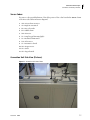
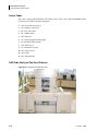
Hematology Specimen Processing
Module with System Manager
ies
00
Ser
15
LH
s
00
ie
Ser
15
LH
LH
15
00
Se
rie
s
A64192AA2
July 2008
FINAL
Beckman Coulter, Inc.
4300 N. Harbor Blvd.
Fullerton, CA 92835
FINAL
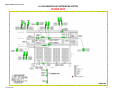
LH 1500® Hematology Automation System
Error Recovery Guide
PN A64192AA2 (July 2008)
Find us on the World Wide Web at:
www.beckmancoulter.com
Beckman Coulter Ireland Inc.
Mervue Business Park,
Mervue, Galway,
Ireland (353 91 774068)
Revision History
Initial Issue, 07/2008
This document applies to the latest software listed and higher versions. When a subsequent software version affects the
information in this document, a new issue will be released.
A64192AA2
FINAL
iii
Revision History
iv
A64192AA2
FINAL
Safety Notice
Read all product manuals and consult with Beckman Coulter-trained personnel before attempting
to operate instrument. Do not attempt to perform any procedure before carefully reading all
instructions. Always follow product labeling and manufacturer’s recommendations. If in doubt as
to how to proceed in any situation, contact your Beckman Coulter representative.
Beckman Coulter, Inc. urges its customers to comply with all national health and safety standards
such as the use of barrier protection. This may include, but is not limited to, protective eyewear,
gloves, and suitable laboratory attire when operating or maintaining this or any other automated
laboratory analyzer.
Alerts for Warning and Caution
WARNING
WARNING indicates a potentially hazardous situation, which, if not avoided, could
result in death or serious injury. May be used to indicate the possibility of
erroneous data that could result in an incorrect diagnosis.
CAUTION
CAUTION indicates a potentially hazardous situation, which, if not avoided, may
result in minor or moderate injury. It may also be used to alert against unsafe
practices. May be used to indicate the possibility of erroneous data that could
result in an incorrect diagnosis.
A64192AA2
FINAL
v
Safety Notice
Alerts for Warning and Caution
WARNING
Risk of operator injury if:
• All doors covers and panels are not closed and secured in place prior to and
during instrument operation.
• The integrity of safety interlocks and sensors is compromised.
• Instrument alarms and error messages are not acknowledged and acted upon.
• You contact moving parts.
• You mishandle broken parts.
• Doors, covers and panels are not opened, closed, removed and/or replaced
with care.
• Improper tools are used for troubleshooting.
To avoid injury:
• Keep doors, covers and panels closed and secured in place while the
instrument is in use.
• Take full advantage of the safety features of the instrument.
• Acknowledge and act upon instrument alarms and error messages.
• Keep away from moving parts.
• Report any broken parts to your Beckman Coulter Representative.
• Open/remove and close/replace doors, covers and panels with care.
• Use the proper tools when troubleshooting.
CAUTION
System integrity could be compromised and operational failures could occur if:
• This equipment is used in a manner other than specified. Operate the
instrument as instructed in the product manuals.
• You introduce software that is not authorized by Beckman Coulter into your
computer. Only operate your system’s software with software authorized by
Beckman Coulter.
• You install software that is not an original copyrighted version. Only use
software that is an original copyrighted version to prevent virus
contamination.
CAUTION
If you purchased this product from anyone other than Beckman Coulter or an
authorized Beckman Coulter distributor, and, it is not presently under a Beckman
Coulter service maintenance agreement, Beckman Coulter cannot guarantee that
the product is fitted with the most current mandatory engineering revisions or
that you will receive the most current information bulletins concerning the
product. If you purchased this product from a third party and would like further
information concerning this topic, call your Beckman Coulter Representative.
vi
A64192AA2
FINAL
Contents
Revision History, iii
Safety Notice, v
CHAPTER 1:
Error Recovery Procedures, 1-1
General Error Recovery, 1-1
Error Code Tables, 1-2
Sensor Codes, 1-2
Unit Error Code Categories, 1-3
Error Recovery Shutdown, 1-5
Error Recovery Startup, 1-6
Disabling the LH Unit Block(s) from the Line Controller, 1-7
Removing Cassettes from the Connection Unit, 1-8
Loading Cassettes in the Connection Unit, 1-10
Secondary Analysis Mode on the LH 1500 System, 1-11
STAT-CASS Mode, 1-12
Bypassing the Connection Unit Table, 1-13
CHAPTER 2:
Outlet Unit Error Recovery Codes, 2-1
Outlet Unit Error Recovery Codes, 2-1
CHAPTER 3:
Outlet Unit, 3-1
Outlet Unit Pictures, 3-1
Outlet Unit Sensor Codes, 3-3
Sensor Codes, 3-4
CHAPTER 4:
Inlet Unit Error Recovery , 4-1
Inlet Unit Error Recovery Codes, 4-1
vii
Contents
CHAPTER 5:
Inlet Unit, 5-1
Inlet Unit Pictures, 5-1
Inlet Unit Sensor Codes, 5-3
Sensor Codes, 5-4
CHAPTER 6:
Connection Unit, 6-1
Connection Unit Error Recovery, 6-1
CHAPTER 7:
Connection Unit Conveyor, 7-1
Connection Unit Conveyor Pictures, 7-1
Connection Unit Conveyor, 7-3
Sensor Codes, 7-4
Connection Unit Loading and Unloading Arms (Pictures), 7-4
Connection Unit Loading and Unloading Arms (Diagram), 7-6
Sensor Codes:, 7-7
Connection Unit Side View (Pictures), 7-7
Connection Unit Side View (Diagram), 7-9
Sensor Codes:, 7-10
Connection Unit Top View (Pictures), 7-10
Connection Unit Top View (Diagram), 7-12
Sensor Codes:, 7-13
CHAPTER 8:
Stockyard Unit, 8-1
Stockyard Unit Error Recovery, 8-1
CHAPTER 9:
Stockyard Unit Conveyor, 9-1
Stockyard Unit Conveyor Pictures, 9-1
Stockyard Unit Conveyor, 9-3
Sensor Codes, 9-4
Stockyard Unit H Lane (Pictures), 9-4
Stockyard Unit H Lane (Diagram), 9-6
Sensor Codes, 9-7
Stockyard Unit T Lane (Pictures), 9-7
Stockyard Unit T Lane (Diagram), 9-9
Sensor Codes, 9-10
3000 Tube Stockyard Top View (Pictures), 9-10
3000 Tube Stockyard Top View (Diagram), 9-12
Sensor Codes, 9-13
300 mm Sorting Lane (Pictures), 9-13
300 mm Sorting Lane (Diagram), 9-15
Sensor Codes, 9-16
600 mm I Lane (Pictures), 9-16
600 mm I Lane (Diagram), 9-18
Sensor Codes, 9-19
900 mm I Lane (Pictures), 9-19
900 mm I Lane (Diagram), 9-21
viii
Contents
Sensor Codes, 9-22
Abbreviations, Abbreviations-1
Beckman Coulter, Inc.
Customer End User License Agreement, Warranty-1
Trademarks, Trademarks-1
ix
Tables
Tables
1.1
Error Codes, 1-3
2.1
Outlet Unit Error Codes, 2-1
4.1
Inlet Unit Error Codes, 4-1
6.1
Connection Unit Error Codes, 6-1
8.1
Stockyard Unit Error Recovery Codes, 8-1
x
Figures
Figures
xii
1.1
Cassette Handling Mechanism, 1-9
1.2
LH Cassette Handling Mechanism, 1-11
3.1
Outlet Unit, 3-1
3.2
Outlet Unit Transfer Arm, 3-2
3.3
Outlet Unit Conveyor, 3-2
3.4
Outlet Unit Sensor Codes, 3-3
5.1
Inlet Unit, 5-1
5.2
Inlet Unit Transfer Arm, 5-2
5.3
Inlet Unit Conveyor, 5-2
5.4
Inlet Unit Sensor Codes, 5-3
7.1
Connection Unit Conveyor Side View, 7-1
7.2
Connection Unit Conveyor Top View, 7-2
7.3
Connection Unit Conveyor, 7-3
7.4
Connection Unit Overall View, 7-4
7.5
Connection Unit Loading and Unloading Arms, 7-5
7.6
Connection Unit Loading and Unloading Arms, 7-6
7.7
Connection Unit Overall View, 7-7
7.8
Connection Unit Side View, 7-8
7.9
Connection Unit Side View, 7-9
7.10
Connection Unit Overall View, 7-10
7.11
Connection Unit Top View, 7-11
7.12
Connection Unit Top View, 7-12
9.1
Stockyard Unit Overall Rear View, 9-1
9.2
Stockyard Unit Conveyor Top View, 9-2
9.3
Stockyard Unit Conveyor Sensor Codes, 9-3
9.4
Stockyard Unit H Lane Side View, 9-4
9.5
Stockyard Unit H Lane Top View, 9-5
9.6
Stockyard Unit H Lane, 9-6
9.7
Stockyard Unit T Lane Side View, 9-7
9.8
Stockyard Unit T Lane Top View, 9-8
9.9
Stockyard Unit T Lane, 9-9
9.10
Stockyard Unit Overall Rear View, 9-10
9.11
Sotckyard Unit Top View Loading and Retrieivng Arms, Loading and Retrieiving Shuttle Cups and Transfer Arms, 9-11
9.12
3000 Tube Stockyard Top View, 9-12
Figures
9.13
300 mm Sorting Lane Side View, 9-13
9.14
300 mm Sorting Lane Top View, 9-14
9.15
mm Sorting Lane, 9-15
9.16
600 mm I Lane Side View, 9-16
9.17
600 mm I Lane Top View, 9-17
9.18
600 mm I Lane, 9-18
9.19
900 mm I Lane Side View, 9-19
9.20
900 mm I Lane Top View, 9-20
9.21
900 mm I Lane, 9-21
xiii
CHAPTER 1
Error Recovery Procedures
General Error Recovery
When a problem occurs at a unit, an audible alarm sounds and flashing warning lights activate. The
keypad display at the affected unit will show which error code the problem generated. The error
code is a three-digit number, which the keypad display shows in two segments (for example, "1-50").
The error code and sensor in question will also be displayed in red on the bottom left hand corner
of the Line Controller until the alarm is silenced. The unit generating the error code will also be
highlighted in red on the Line Controller until error is cleared.
A64192AA2
1
Press the ALARM button on the keypad of the affected unit to silence the alarm.
2
Read the first one-digit segment of the error code on the keypad display on the affected unit.
3
Press the FUNCTION (-) button on the keypad to view the second two-digit segment of the error
code on the keypad display. The combination of the first one-digit segment and second twodigit segment gives the complete three-digit error code used for troubleshooting the problem.
4
Refer to the Error Code tables for the appropriate Unit Error Code. For example, if the error
occurs at the Outlet Unit, refer to Table 2.1, Outlet Unit Error Codes.
5
Look up the error code in the Keypad Display column of the error code table.
6
Read the information in the Sensor, Problem, and Solution columns for that error code. Do not
yet attempt to perform the steps suggested in the Solution column.
7
Locate the sensor on the appropriate Unit Sensor Diagram by using the Grid Ref (Grid
Reference). On the edges of the sensor diagram highlighted in Yellow is the locating reference
grid. Follow the appropriate letter and number to the intersecting area on the sensor diagram.
The sensor in error is located in the intersecting area.
FINAL
1-1
Error Recovery Procedures
Error Code Tables
8
Locate the actual sensor in error on the unit. The sensor in error is labeled on the unit.
9
Spend a moment looking at the hardware and try to find the cause of the problem.
10 After investigating the cause of the error, now perform the steps suggested in the Solution
column.
11 Press PAUSE/RUN to resume routine operations. Pay attention to the area around the sensor that
generated the error. Ensure that the error has been resolved.
12 If the problem persists, repeat the procedure.
13 Call your Beckman Coulter Representative for any unrecoverable errors.
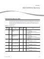
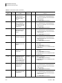
Error Code Tables
The Error Code tables describe error messages generated by the LH 1500 Hematology Automation
System. The tables provide the system error codes, the related sensor, a location reference point on
the appropriate schematic diagram and a brief explanation of the possible problem and possible
solutions.
1. Keypad Display: Contains the codes displayed on the keypads located at each unit of the system.
2. Sensor: Contains the alphanumeric codes as they appear in the Line Controller's Error Log.
These codes, (for example, "SN50") refer to specific sensors.
3. Problem: Provides a description of the cause of the error.
4. Sensor Diagram: Provides the name and location of the appropriate schematic diagram.
5. Grid Ref (Reference): Contains the reference position of the sensor on the appropriate
schematic diagram.
6. Solution: Provides a way to resolve an error condition.
Sensor Codes
The sensor codes provide definitions of the alpha portion of the codes found in the Sensor column
of the Error Code tables and Sensor diagrams.
1. AM = AC synchronous motor
2. AS = Magnetic autoswitch
1-2
A64192AA2
FINAL
Error Recovery Procedures
Unit Error Code Categories
3. BR = Bar-code reader
4. BZ = Audible alarm
5. DM = DC motor
6. LP = Lamp (keypad & warning light)
7. LS = Mechanical limit switch
8. PM = Pulse motor
9. SL = Pneumatic solenoid
10. SM = Stepper motor
11. SN = Sensor
12. SW = Keypad switch
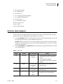
Unit Error Code Categories
An Error Code is a three-digit number. The keypad on the unit in error first shows the one-digit
segment. The first one-digit segment represents the error category.
1. Press the FUNCTION (-) button on the keypad to show the second two-digit segment. The second
two-digit segment refers to a specific numbered component.
Example: If the Error Code is 1-47 on a Connection Unit, it represents Sensor number 47 (SN47).
This Error Code means that the sensor associated with the right safety cover over the Loading
Arm detected a problem.
2. Press the FUNCTION (+) and FUNCTION (-) button alternately to toggle back and forth to see both
sets of digit segments.
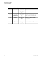
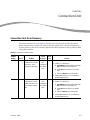
Table 1.1 Error Codes
Category
Problem
Error Description
Solution
0-xx
Bar-code
Bar-Code Error
1. Ensure bar-code is properly positioned on
sample tube in relation to sample tube
carrier.
2. Ensure bar-code is readable.
3. Ensure the bar-code spinners are properly
working.
(BUZZxx)
1-xx
Sensor
Sensor Error (SNxx) Check the sensor position and look for
(Can also refer to possible obstruction.
ASxx)
2-xx
Pneumatic Solenoid
Pneumatic Solenoid
Error (BUZZxx)
Check the pneumatic solenoid and look for
possible obstruction.
3-xx
Bar-Code Reader
Bar-Code reader
Error
Check that the bar-code reader light comes
on and that the carrier rotates properly.
(BRxx)
A64192AA2
FINAL
1-3
1
Error Recovery Procedures
Unit Error Code Categories
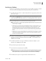
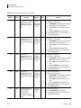
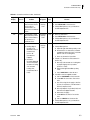
Table 1.1 Error Codes (Continued)
Category
Problem
Error Description
4-xx
Pulse Motor/AC Motor
Pulse Motor/AC
Motor Error
Solution
Check the motor and/or belt drive.
(PMxx, SMxx or
DMxx)
5-xx
7-xx
LH 750 Analyzer to
Connection Unit
Communication
Communication
Error
Auto Sensor
Auto Sensor Error
(LHxx)
(ASxx)
9-xx
1-4
Ensure that the Analyzer is Ready or the
cassette is loading or unloading properly.
Ensure that the pneumatic solenoid is
working properly.
Loading or Unloading AC motor on Loading Check the Loading or Unloading Arm motor.
Arm AC Motor
or Unloading Arm
Error (AMxx)
A64192AA2
FINAL
Error Recovery Procedures
Error Recovery Shutdown
Error Recovery Shutdown
The Error Recovery Shutdown procedure takes the LH 1500 system offline, stopping the command
of the Line Controller, interrupting LIS interfacing and powering off the automation line.
1
If possible, allow all specimens to complete analysis and arrive at appropriate positions on the
Outlet and Stockyard.
2
If possible, press PAUSE/RUN button on the Outlet Unit keypad. Verify all sample tube carriers
(pucks) stop behind the Outlet Unit and there are no moving sample tube carriers on the track.
3
Ensure all sample tubes are removed from the tracks and Connection Units.
NOTE Once a specimen is scanned at the bar-code reader inside the Connection Unit, the Line Controller
assumes analysis is complete.
• During Error Recovery there may be unanalyzed specimens in a Connection Unit or on a
LH 750. Unanalyzed specimens must be analyzed by Secondary Analysis Mode or STATCASS Mode after Error Recovery. If not, the unanalyzed specimens will route to the
Stockyard or Outlet if placed back on the LH 1500 System without being analyzed by the
LH 750.
• During Error Recovery specimens that have been analyzed by the LH 750, but not routed out
of the Connection Unit, can be placed back on the LH 1500 System and will be properly
routed to the Stockyard or Outlet.
4
At the Line Controller Main Menu screen Menu Bar, select System Operation > Shutdown. The
Shutdown screen appears. If Shutdown is desired, select <OK>. To cancel Shutdown, select
<Cancel>, then Select <OK>.
5
The Shutdown Reminder screen appears. If Shutdown is desired, select <OK>. To cancel
Shutdown, select <Cancel>, then Select <OK>.
6
Ensure that the System Status box is Ready.
7
Ensure that the Host Communication box is Offline.
NOTE While the Host Communication box is Offline, the LIS interfacing will be interrupted. LIS operations
will be compromised. Do not allow the Host Communications to be Offline for extended periods.
Perform System Startup to reset Host Communication to Online and restore LIS interfacing.
8
A64192AA2
FINAL
The Shutdown in Progress screen appears briefly on the Main Menu screen.
1-5
1
Error Recovery Procedures
Error Recovery Startup
9
Press the red power OFF button on the Inlet Unit and turn off the automation line.
NOTE Wait 60 seconds before pressing the green power ON button.
Error Recovery Startup
The Error Recovery Startup procedure brings the LH 1500 system online; powering on the
automation line, re-initializing robotics, restoring LIS interfacing and command to the Line
Controller.
1
Complete System Shutdown Procedure.
2
Ensure the LH 755 Analyzers are powered up including: LH 750 Analyzers, Workstations,
Slide Makers and Slide Stainers, if applicable.
3
On the LH Unit Blocks and Tracks remove any tubes and/or foreign objects.
4
Ensure the yellow emergency Stop buttons are in the "Out" position (not pushed) on all LH 1500
system components.
5
Press the green power ON button on the Inlet Unit to power on the automation line.
6
Select System Operation > Startup on the Main Menu Screen Menu Bar. The Startup screen
displays and shows the options available for managing sample data while performing Startup
on the LH 1500 System.
7
The following options are available:
• Delete Processed Samples Only - (default selection) This function looks at all processed
samples, and unprocessed samples more than 72 hours old, and deletes them (includes
exchanged racks). This deletion does not affect the stockyard or UDR racks, although
samples in the Error rack and Pending rack will be deleted.
• Do Not Delete - saves all of the data currently in the Line Controller.
• Delete All Sample Data - deletes all data currently in the Line Controller. Select <Do Not
Delete>
8
1-6
Select <OK> in the Startup screen to have the robotics initializes.
A64192AA2
FINAL
Error Recovery Procedures
Disabling the LH Unit Block(s) from the Line Controller
9
Check for any Units that are Magenta colored. This means that there is a communication error
between the Line Controller and the LH 1500 System. It may be necessary to:
• Perform the Shutdown procedure. Select Exit on the Main Menu Screen Menu Bar at the
Line Controller and ensure the Line Controller computer powers off. Press the red power
OFF button at the Inlet Unit to power off the automation line and wait one minute. First.
power on the automation line by pressing the green power ON button at the Inlet Unit.
Second, turn the Line Controller computer on, then perform the Startup procedure.
• Follow the LIS Guidelines to troubleshoot the communication error.
10 Ensure that the System Status box is Active.
11 Ensure that the Host Communication box is Online.
NOTE If Host Communication box is Offline, follow the LIS Guidelines to re-establish communication.
12 Ensure that the Connection units have four cassettes loaded properly.
13 Ensure all LH 1500 system components are running (not paused) and all LH Unit blocks are
properly Enabled (Auto Mode).
14 Continue with normal operation.
Disabling the LH Unit Block(s) from the Line Controller
The term LH Unit Block is defined as: The grouping of instrumentation consisting of a Connection
Unit and a LH 750 or LH 755 run by the Line Controller computer. Disabling and Enabling LH Unit
Blocks from the Line Controller is a workflow control tool during Routine Tasks or Extended Error
Recovery. Disabling an entire LH Unit Block does not allow routing of any new specimens to the
disabled Unit Block(s). The Line Controller then routes all new specimens to the enabled LH Unit
Block(s). Specimens remaining on the disabled LH Unit Block will be analyzed, off-loaded from the
Connection Unit and routed to their destination.
A64192AA2
1
At the Line Controller Main Menu, select the <Setup> button from the appropriate LH Unit
Block to be disabled.
2
At the LH Analyzer Setup Screen Connection Area, select <Enable> to enable LH Unit Block. To
disable Unit LH Block select <Disable>.
FINAL
1-7
1
Error Recovery Procedures
Removing Cassettes from the Connection Unit
3
4
Select <OK> to save changes or Select <Cancel> to exit.
5
Perform the Routine Tasks or Error Recovery procedure.
Select <OK> and return to the Main Menu. Enabled LH Unit Blocks appear off-white. Disabled
Unit blocks appear gray.
NOTE
6
•
After a Connection Unit is Disabled, the Loading and Unloading Arms pause once all specimens
have been off-loaded from the LH 750 Analyzer. The Loading and Unloading Arm Covers can
then be removed.
•
While a Connection Unit is Disabled, that Connection Unit must be in STAT-CASS Mode to load
cassettes from the right side loading bay.
•
If all Connection Units are disabled, all new specimens and unanalyzed specimens on the
LH 1500 System must be analyzed by Secondary Analysis Mode or STAT-CASS Mode.
To re-enable the appropriate LH Unit Block perform Steps 1-3, but Select <Enable> at Step 2.
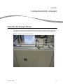
Removing Cassettes from the Connection Unit
Proper removal of the cassettes in a Connection Unit minimizes system errors.
1
Remove the right-side tabletop access cover of the Connection Unit and set aside. The
Connection Unit will PAUSE.
2
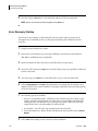
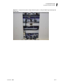
Remove cassette from position number one. Refer to Figure 1.1, Cassette Handling Mechanism.
NOTE When recovering from a cassette jam, it may not be possible to remove cassettes at position
number one due to excessive Errors and/or Alarms. If so, proceed to Step 7.
1-8
3
Replace the right-side tabletop access cover; ensure sensor trigger in the far left corner is
properly positioned.
4
Press the PAUSE/RUN button on Connection Unit. Allow the next cassette to advance to position
number one.
5
Repeat steps 1 through 4 until third cassette is ready to be removed.
A64192AA2
FINAL
Error Recovery Procedures
Removing Cassettes from the Connection Unit
6
Remove third cassette at position number one. At the same time remove the fourth (last)
cassette at position number six. Proceed to Step 9.
7
Remove the right-side tabletop access cover and remove the front covers of the Connection
Unit, and set aside.
8
Remove all four of the cassettes from the Connection Unit.
NOTE Once a specimen is scanned by the bar-code reader inside the Connection Unit, the Line
Controller assumes analysis is complete.
9
•
During Error Recovery there may be unanalyzed specimens in a Connection Unit or on a LH 750.
Unanalyzed specimens must be analyzed by Secondary Analysis Mode or STAT-CASS Mode. If
not, the unanalyzed specimens will go to the Stockyard or Outlet if placed back on the LH 1500
System.
•
During Error Recovery specimens that have been analyzed by the LH 750, but not routed out of
the Connection Unit, can be placed back on the LH 1500 System, and will be properly routed to
the Stockyard or Outlet.
Replace the front covers back into their proper positions and/or the right-side tabletop access
cover.
10 Press the PAUSE/RUN button on Connection Unit. Ensure there are no errors displayed on the
keypad.
NOTE If errors persist due to a cassette jam, see Loading Cassettes in the Connection Unit. Multiple
Errors and Alarms may occur. Continue to PAUSE/RUN and/or load cassettes until errors are cleared.
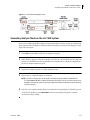
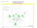
Figure 1.1 Cassette Handling Mechanism
A64192AA2
FINAL
1-9
1
Error Recovery Procedures
Loading Cassettes in the Connection Unit
Loading Cassettes in the Connection Unit
Proper loading of the cassettes minimizes system errors and allows the Connection Unit to
accurately organize the cassettes.
1
Before loading cassettes into a LH Connection Unit, ensure that the:
• LH 1500 robotic line has initialized with no errors.
• LH connection keypad LED indicates the AUTO status.
• LH connection Unit has not detected an error (if possible).
2
Remove the right-side tabletop access cover of the Connection Unit and set aside. The
Connection Unit will Pause.
3
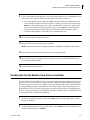
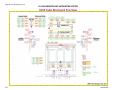
Load the first cassette at position #5 (the label must face away from operator). Refer to
Figure 1.2, LH Cassette Handling Mechanism.
4
Replace the right-side tabletop access cover back into the proper safety position; make sure the
sensor in the upper left corner is properly positioned.
5
Press the PAUSE/RUN button on Connection Unit. Allow the cassette to advance to position
number six.
6
Repeat steps 2 through 5 swiftly until fourth (last) cassette is loaded onto Connection Unit.
Timing is crucial. Do not exceed the maximum number of four cassettes.
NOTE
7
•
Do not place more than one cassette at a time on the Connection Unit.
•
Do not insert next cassette if another cassette is in position number four, wait until cassette
advances to position number six.
Ensure the cassettes have fully cycled and no errors are displayed on the keypad.
NOTE Home cassette positions are indicated by red outlined areas (Position number one, Position
number five, Position number six and Position number eight).
1-10
A64192AA2
FINAL
Error Recovery Procedures
Secondary Analysis Mode on the LH 1500 System
Figure 1.2 LH Cassette Handling Mechanism
Secondary Analysis Mode on the LH 1500 System
The use of Secondary Mode allows analysis of specimens without track processing. Secondary Mode
is the quickest mode of analysis for STAT specimens when numerous specimens are being processed
by the LH 1500 System.
1
Press STOP one time ONLY on the LH 750 Analyzer's keypad.
2
When "READY" appears on the LH 750 Analyzer use the bar-code wand and scan the sample ID
in the Bar-code field into the LH 750 Workstation Command Center, or input the sample ID into
the LH 750 Analyzer numeric keypad.
3
Aspirate the sample using the secondary aspiration probe.
4
Repeat steps 2 - 3 until all samples are analyzed.
NOTE If numerous samples are to be analyzed in Secondary Mode, proceed to DISABELING THE
LH 1500 CONNECTION UNIT Procedure. Disabling the Connection Unit will allow the workload to be
diverted to the other instrument. Processing samples while PAUSED will back-up the workload during
Secondary Analysis.
A64192AA2
5
After the cycle completes and results are received at the LH 750 Workstation ("READY" appears
on the LH 750 Analyzer), press START/CONT on the LH 750 Analyzer's keypad to continue
automatic mode processing.
FINAL
1-11
1
Error Recovery Procedures
STAT-CASS Mode
STAT-CASS Mode
The STAT-CASS mode (manual cassette mode) of operation allows processing of cassettes without
automation loading and unloading.
1
Press the STAT-CASS button one time only to select the STAT-CASS mode of operation. The
LH Connection Unit stops cassette loading from the Connection Unit Loading Arm to the
LH Analyzer. (Samples currently being processed on the LH 750 Analyzer complete analysis and
return to the Connection Unit for unloading.)
2
Wait until the STAT-CASS LED stops flashing and is continuously lit before loading the manual
cassette.
3
Remove the Loading and Unloading Arm covers at the LH Connection Unit.
4
Place the manual cassettes into the LH 750 Analyzer's right-side loading bay.
5
After analysis completes ("READY" appears on the LH 750 Analyzer), remove the finished
cassettes from the left-side unloading bay.
NOTE Ensure that the manual cassettes are removed from the LH 750 Analyzer before replacing the
Loading and Unloading Arm covers.
6
Replace the Loading and Unloading Arm covers.
7
Press STAT-CASS to end the STAT-CASS mode of operation and return the LH Connection Unit to
normal AUTO mode.
NOTE During the STAT-CASS mode of operation, the LH Connection Unit continues to load samples into
cassettes. Samples inside the Connection Unit are held for later processing. However, 15 minutes of
operation in the STAT-CASS mode generates a time-out error for samples held in the Connection Unit.
The Unit will continue to alarm audibly without an error code until the manual cassettes are removed,
the covers replaced and the STAT-CASS mode is deselected.
1-12
A64192AA2
FINAL
Error Recovery Procedures
Bypassing the Connection Unit Table
Bypassing the Connection Unit Table
In the event of an unrecoverable error condition due to hardware errors at the Connection Unit
Table, the Connection Unit will PAUSE and prevent samples from being processed. Utilizing
Function 97 will bypass the Connection Unit Table allowing processing of samples by the
Connection Unit Conveyor bar-code reader.
1
Perform the Error Recovery Shutdown procedure of the LH 1500 System.
2
Perform the Error Recovery Startup procedure of the LH 1500 System.
3
Ensure that the Connection Unit is in MANUAL MODE (the green LED pointing to MANUAL is
ON) and the keypad displays the numbers 00.
If not, press and hold down the AUTO/MANUAL key for 10 seconds until the green LED next to
MANUAL is ON.
A64192AA2
4
Press the FUNCTION (-) key to advance the display to number 97.
5
Press the ENTER key.
6
Ensure that the sample tube bar-code labels are successfully being read at the Conveyor Unit
Conveyor bar-code reader (BR02) by observing that the green LED on back of the bar-code
reader turns ON when it reads the sample tube label.
FINAL
1-13
1
Error Recovery Procedures
Bypassing the Connection Unit Table
1-14
A64192AA2
FINAL
CHAPTER 2
Outlet Unit Error Recovery Codes
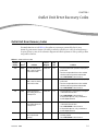
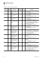
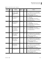
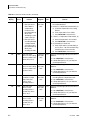
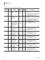
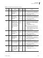
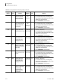
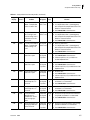
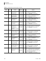
Outlet Unit Error Recovery Codes
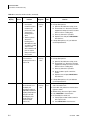
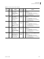
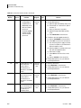
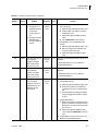
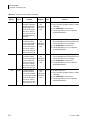
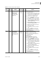
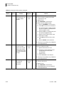
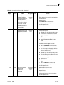
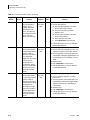
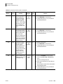
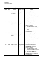
The Outlet Unit Error Code Table 2.1 describes error messages generated by the LH 1500
Hematology Automation System. The table provides the system error codes, the related sensor, a
location reference point on the schematic diagram and a brief explanation of the possible problem
and possible solutions.
Table 2.1 Outlet Unit Error Codes
Keypad
Display
Sensora
Problem
0-00
BZ00
0-01
Sensor
Diagram
Grid
Ref
Bar-code label did not
read or was incorrectly
positioned on tube.
Outlet Unit
B-3
1. Ensure the bar-code is present and properly
positioned.
2. Turn the sample tube in the carrier at BR01
with bar-code facing the bar-code reader.
3. Press PAUSE/RUN to clear the error.
BZ01
Bar-code label did not
read or was incorrectly
positioned on tube.
Outlet Unit
B-3
1. Ensure the bar-code is present and properly
positioned.
2. Turn the sample tube in the carrier at BR01
with bar-code facing the bar-code reader.
3. Press PAUSE/RUN to clear the error.
1-01
SN01
Outlet Transfer Arm
error finding the X-axis
home position.
Outlet Unit
D-3
1. Ensure there are no obstructions in the path
of the Outlet Transfer Arm.
2. Press PAUSE/RUN to clear the error.
If the problem persists, call your Beckman
Coulter Representative.
1-02
SN02
Outlet Transfer Arm
error finding the X-axis
home position.
Outlet Unit
D-3
1. Ensure there are no obstructions in the path
of the Outlet Transfer Arm.
2. Press PAUSE/RUN to clear the error.
3. If the problem persists, call your Beckman
Coulter Representative.
1-05
SN05
Outlet rack #1 from the
left not positioned
correctly.
Outlet Unit
D-3
1. Ensure that Outlet rack #1 is in place and
correctly seated.
2. Press PAUSE/RUN to clear the error.
A64192AA2
FINAL
Solution
2-1
Outlet Unit Error Recovery Codes
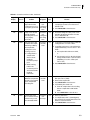
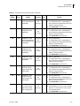
Outlet Unit Error Recovery Codes
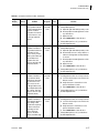
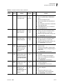
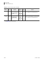
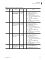
Table 2.1 Outlet Unit Error Codes (Continued)
Keypad
Display
Sensora
Problem
1-06
SN06
1-07
Sensor
Diagram
Grid
Ref
Outlet rack #2 from the
left not positioned
correctly.
Outlet Unit
D-4/5
1. Ensure that Outlet rack #2 is in place and
correctly seated.
2. Press PAUSE/RUN to clear the error.
SN07
Outlet rack #3 from the
left not positioned
correctly.
Outlet Unit
D-5
1. Ensure that Outlet rack #3 is in place and
correctly seated.
2. Press PAUSE/RUN to clear the error.
1-08
SN08
Outlet rack #4 from the
left not positioned
correctly.
Outlet Unit
D-5
1. Ensure that Outlet rack #4 is in place and
correctly seated.
2. Press PAUSE/RUN to clear the error.
1-09
SN09
Sample tube carrier
error at Outlet bar-code
reader.
Outlet Unit
C-3
1. Clear any obstruction.
2. If a sample tube carrier is jammed, gently
twist and push the sample tube carrier in the
direction of least resistance.
3. Press PAUSE/RUN to clear the error.
1-10
SN10
Fiber optic sensor did
not detect a sample
tube at Outlet bar-code
reader BR01.
Outlet Unit
C-3
1. Locate missing tube and place into the
waiting carrier.
2. Press PAUSE/RUN to clear the error.
1-11
SN11
Proximity sensor did
not detect a sample
tube carrier released
from the Outlet barcode reader.
Outlet Unit
B2
1. Clear any obstruction.
2. If a sample tube carrier is jammed, gently
twist and push the sample tube carrier in the
direction of least resistance.
3. Press PAUSE/RUN to clear the error.
1-12
SN12
Sample tube carrier
proximity sensor error
before the Outlet barcode reader.
Outlet Unit
C-4
This error occurs during Power On, if the sensor
is defective.
Sample tube carrier
proximity sensor error
at the Outlet waiting
queue.
Outlet Unit
Sample tube carrier
error at the Outlet
return track.
Outlet Unit
Proximity sensor did
not detect a sample
tube carrier from the
return track.
Outlet Unit
1-13
1-16
1-18
2-2
SN13
SN16
SN18
Solution
1. Press PAUSE/RUN to clear the error.
C-4
This error occurs during Power On, if the sensor
is defective.
1. Press PAUSE/RUN to clear the error.
B-5
This error occurs during Power On, if the sensor
is defective.
1. Press PAUSE/RUN to clear the error.
C-4
1. Clear any obstruction.
2. If a sample tube carrier is jammed, gently
twist and push the sample tube carrier in the
direction of least resistance.
3. Press PAUSE/RUN to clear the error.
A64192AA2
FINAL
Outlet Unit Error Recovery Codes
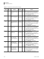
Outlet Unit Error Recovery Codes
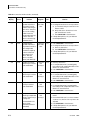
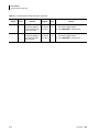
Table 2.1 Outlet Unit Error Codes (Continued)
Keypad
Display
Sensora
1-19
SN19
1-20
Sensor
Diagram
Grid
Ref
Proximity sensor did
not detect a sample
tube carrier entering
the Outlet waiting
queue.
Outlet Unit
C-4
1. Clear any obstruction.
2. If a sample tube carrier is jammed, gently
twist and push the sample tube carrier in the
direction of least resistance.
3. Press PAUSE/RUN to clear the error.
SN20
Outlet Transfer Arm
error finding the Y-axis
home position.
Outlet Unit
C-5
1. Ensure the Outlet Transfer Arm movement is
not obstructed.
2. Press PAUSE/RUN to clear the error.
3. If the problem persists, call your Beckman
Coulter Representative.
1-21
SN21
Outlet Transfer Arm
error finding the Y-axis
home position.
Outlet Unit
C-5
1. Ensure the Outlet Transfer Arm movement is
not obstructed.
2. Press PAUSE/RUN to clear the error.
3. If the problem persists, call your Beckman
Coulter Representative.
2-01
SL01
Outlet Transfer Arm Zaxis cylinder SL01 did
not fully extend /
retract and misses
activating the limit
sensor.
Outlet Unit
2-03
SL03
Stopper error at the
Outlet sample tube
carrier loading/
unloading position.
Outlet Unit
Problem
Solution
Transfer 1. Clear any obstruction.
2. Press PAUSE/RUN to clear the error.
Arm
3. If the problem persists, call your Beckman
Coulter Representative.
B-3
b
1. Clear any obstruction.
2. If a sample tube carrier is jammed, gently
twist and push the sample tube carrier in the
direction of least resistance.
3. Press PAUSE/RUN to clear the error.
2-04
SL04
Stopper error at the
Outlet sample tube
carrier loading/
unloading position.
Outlet Unit
B-4
1. Clear any obstruction.
2. If a sample tube carrier is jammed, gently
twist and push the sample tube carrier in the
direction of least resistance.
3. Press PAUSE/RUN to clear the error.
2-05
SL05
Stopper error before
the Outlet sample tube
carrier loading/
unloading position.
Outlet Unit
B-4
1. Clear any obstruction.
2. If a sample tube carrier is jammed, gently
twist and push the sample tube carrier in the
direction of least resistance.
3. Press PAUSE/RUN to clear the error.
2-06
SL06
Stopper error at Outlet
waiting queue lane
Outlet Unit
C-4
1. Clear any obstruction.
2. If a sample tube carrier is jammed, gently
twist and push the sample tube carrier in the
direction of least resistance.
3. Press PAUSE/RUN to clear the error.
A64192AA2
FINAL
2-3
2
Outlet Unit Error Recovery Codes
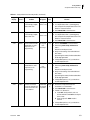
Outlet Unit Error Recovery Codes
Table 2.1 Outlet Unit Error Codes (Continued)
Keypad
Display
Sensora
Problem
2-07
SL07
2-08
SL08
Sensor
Diagram
Grid
Ref
Stopper error at Outlet
waiting queue lane.
Outlet Unit
C-3/4
1. Clear any obstruction.
2. If a sample tube carrier is jammed, gently
twist and push the sample tube carrier in the
direction of least resistance.
3. Press PAUSE/RUN to clear the error.
Outlet Divider Arm
error at the exit of the
waiting queue.
Outlet Unit
C-3
1. Ensure the gate arm is free to extend and
retract.
2. Verify the Divider arm is not slow to open and
close. If so, the cylinder air flow controller
may need adjustment.
3. Press PAUSE/RUN to clear the error.
Outlet Unit
B-3
1. Ensure the gate arm is free to extend and
retract.
2. Verify the Divider arm is not slow to open and
close. If so, the cylinder air flow controller
may need adjustment.
3. Press PAUSE/RUN to clear the error.
Associated with AS08
(retracted) and AS09
(extended).
2-09
SL08 #2 Outlet Divider Arm
error at the main lane.
Associated with AS15
(retracted) and AS16
(extended).
2-10
SL10
Stopper error at Outlet
return lane.
Outlet Unit
B-5
1. Clear any obstruction.
2. If a sample tube carrier is jammed, gently
twist and push the sample tube carrier in the
direction of least resistance.
3. Press PAUSE/RUN to clear the error.
2-11
SL11
Stopper error at Outlet
return lane.
Outlet Unit
B-5
1. Clear any obstruction.
2. If a sample tube carrier is jammed, gently
twist and push the sample tube carrier in the
direction of least resistance.
3. Press PAUSE/RUN to clear the error.
2-12
SL12
Outlet Divider Arm
error at the beginning
of main lane.
Outlet Unit
B-5
1. Ensure the gate arm is free to extend and
retract.
2. Verify the Divider arm is not slow to open and
close. If so, the cylinder air flow controller
may need adjustment.
3. Press PAUSE/RUN to clear the error.
Outlet Unit
B/C-3
a
1. Clear any obstruction.
2. If a sample tube carrier is jammed, gently
twist and push the sample tube carrier in the
direction of least resistance.
3. Press PAUSE/RUN to clear the error.
Associated with AS12
(retracted) and AS13
(extended).
2-13
2-4
Solution
SL13
Stopper error before
the Outlet bar-code
reader.
A64192AA2
FINAL
Outlet Unit Error Recovery Codes
Outlet Unit Error Recovery Codes
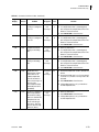
Table 2.1 Outlet Unit Error Codes (Continued)
Keypad
Display
Sensora
Problem
3-01
BR01
4-01
PM01
Sensor
Diagram
Grid
Ref
Failure of the bar-code
reader BR01 to read.
May have lost its
programming.
Outlet Unit
B-3
1. Perform SHUTDOWN at Line Controller.
2. Enter the System Setup > Maintenance
menu.
Default Password=password1
3. Verify correct setting of bar-code label and
exit screen.
Upon exiting the screen the bar-code readers
will be reprogrammed.
4. If the problem persists, call your Beckman
Coulter Representative.
Failure to move the
Outlet Transfer Arm in
the X-axis direction.
Outlet Unit
E-2
1. Ensure the Outlet Transfer Arm movement is
not obstructed.
2. Press PAUSE/RUN to clear the error.
3. If there is no obstruction:
a. Power OFF Outlet Unit, wait one minute
and then Power ON the Outlet Unit to
reset.
Solution
4. If the problem persists, call your Beckman
Coulter Representative.
4-02
PM02
Failure to move the
Outlet Transfer Arm in
the Y-axis direction.
Outlet Unit
B-15
1. Ensure the Outlet Transfer Arm movement is
not obstructed.
2. Press PAUSE/RUN to clear the error.
3. If there is no obstruction:
a. Power OFF Outlet Unit, wait one minute
and then Power ON the Outlet Unit to
reset.
4. If the problem persists, call your Beckman
Coulter Representative.
a. See Abbreviations for a list of sensor codes.
A64192AA2
FINAL
2-5
2
Outlet Unit Error Recovery Codes
Outlet Unit Error Recovery Codes
2-6
A64192AA2
FINAL
CHAPTER 3
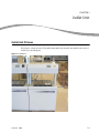
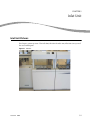
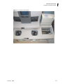
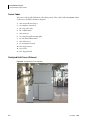
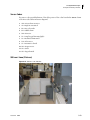
Outlet Unit
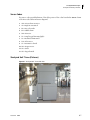
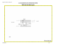
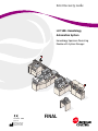
Outlet Unit Pictures
This chapter contains pictures of the Outlet Unit, Outlet Unit Transfer Arm, Outlet Unit Conveyor
and the associated diagrams.
Figure 3.1 Outlet Unit
A64192AA2
FINAL
3-1
Outlet Unit
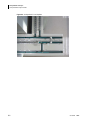
Outlet Unit Pictures
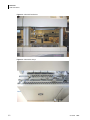
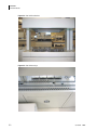
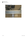
Figure 3.2 Outlet Unit Transfer Arm
Figure 3.3 Outlet Unit Conveyor
3-2
A64192AA2
FINAL
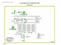
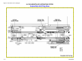
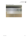
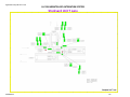
Figure3.4 Outlet Unit Sensor Cods
LH 1500 HEMATOLOGY AUTOMATION SYSTEM
Outlet Unit
A641922AA2
3-3
Outlet Unit
Sensor Codes
Sensor Codes
The sensor codes provide definitions of the alpha portion of the codes found in the Sensor column
of the Error Code tables and Sensor diagrams.
1. AM = AC synchronous motor
2. AS = Magnetic autoswitch
3. BR = Bar-code reader
4. BZ = Audible alarm
5. DM = DC motor
6. LP = Lamp (keypad & warning light)
7. LS = Mechanical limit switch
8. PM = Pulse motor
9. SL = Pneumatic solenoid
10. SM = Stepper motor
11. SN = Sensor
12. SW = Keypad switch
3-4
A64192AA2
FINAL
CHAPTER 4
Inlet Unit Error Recovery
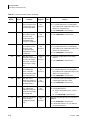
Inlet Unit Error Recovery Codes
The Inlet Unit Error Code Table 4.1 describes error messages generated by the LH 1500 Hematology
Automation System. The table provides the system error codes, the related sensor, a location
reference point on the schematic diagram and a brief explanation of the possible problem and
possible solutions.
Table 4.1 Inlet Unit Error Codes
Keypad
Display
Sensora
1-01
SN01
1-02
1-05
SN02
SN05
Sensor
Diagram
Grid Ref
Inlet Transfer Arm error
finding the X-axis home
position.
Inlet Unit
D-3
Inlet Transfer Arm error
finding the X-axis near
home position.
Inlet Unit
Inlet rack #1 from the left
not positioned correctly.
Inlet Unit
Problem
Solution
1. Ensure there are no obstructions in the path of the
Inlet Transfer Arm.
2. Press PAUSE/RUN to clear the error.
3. If the problem persists, call your Beckman Coulter
Representative.
D-3
1. Ensure there are no obstructions in the path of the
Inlet Transfer Arm.
2. Press PAUSE/RUN to clear the error.
3. If the problem persists, call your Beckman Coulter
Representative.
D-3
1. Ensure that Inlet rack #1 is in place and correctly
seated.
2. Press PAUSE/RUN to clear the error.
1-06
SN06
Inlet rack #2 from the left
not positioned correctly.
Inlet Unit
D-3
1. Ensure that Inlet rack #2 is in place and correctly
seated.
2. Press PAUSE/RUN to clear the error.
1-07
SN07
Inlet rack #3 from the left
not positioned correctly.
Inlet Unit
D-4
1. Ensure that Inlet rack #3 is in place and correctly
seated.
2. Press PAUSE/RUN to clear the error.
1-08
SN08
Inlet rack #4 from the left
not positioned correctly.
Inlet Unit
D-5
1. Ensure that Inlet rack #4 is in place and correctly
seated.
2. Press PAUSE/RUN to clear the error.
A64192AA2
FINAL
4-1
Inlet Unit Error Recovery
Inlet Unit Error Recovery Codes
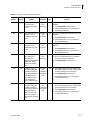
Table 4.1 Inlet Unit Error Codes (Continued)
Sensor
Diagram
Grid Ref
Sample tube carrier failed
to arrive in the time
allotted at the Inlet sample
tube carrier loading
position.
Inlet Unit
C-3
Proximity sensor did not
detect a sample tube
carrier released from the
Inlet sample tube carrier
loading position.
Inlet Unit
Sample tube carrier error
before the Inlet sample
tube carrier loading
position.
Inlet Unit
Keypad
Display
Sensora
Problem
1-09
SN09
1-11
1-12
SN11
SN12
Solution
1. Clear any obstruction.
2. If a sample tube carrier is jammed, gently twist
and push the sample tube carrier in the direction
of least resistance.
3. Press PAUSE/RUN to clear the error.
B-2
1. Clear any obstruction.
2. If a sample tube carrier is jammed, gently twist
and push the sample tube carrier in the direction
of least resistance.
3. Press PAUSE/RUN to clear the error.
C-4
1. Clear any obstruction.
2. If a sample tube carrier is jammed, gently twist
and push the sample tube carrier in the direction
of least resistance.
3. Press PAUSE/RUN to clear the error.
1-13
SN13
Sample tube carrier error
at the Inlet waiting queue.
Inlet Unit
C-4
1. Clear any obstruction.
2. If a sample tube carrier is jammed, gently twist
and push the sample tube carrier in the direction
of least resistance.
3. Press PAUSE/RUN to clear the error.
1-20
1-21
2-01
2-03
SN20
SN21
SL01
SL03
Inlet Transfer Arm error
finding the Y-axis home
position.
Inlet Unit
Inlet Transfer Arm error
finding the Y-axis near
home position.
Inlet Unit
Inlet Transfer Arm Z-axis
cylinder did not fully
extend / retract and
misses activating the limit
sensor. The limit sensors
are AS01 (up) and AS02.
Inlet Unit
Stopper error at the Inlet
sample tube carrier
loading position.
Inlet Unit
C-5
1. Ensure the Inlet Transfer Arm movement is not
obstructed.
2. Press PAUSE/RUN to clear the error.
3. If the problem persists, call your Beckman Coulter
Representative.
C-5
1. Ensure the Inlet Transfer Arm movement is not
obstructed.
2. Press PAUSE/RUN to clear the error.
3. If the problem persists, call your Beckman Coulter
Representative.
Transfer
Arm
B/C-3
1. Clear any obstruction.
2. Press PAUSE/RUN to clear the error.
3. If the problem persists, call your Beckman Coulter
Representative.
1. Clear any obstruction.
2. If a sample tube carrier is jammed, gently twist
and push the sample tube carrier in the direction
of least resistance.
3. Press PAUSE/RUN to clear the error.
2-04
SL04
Stopper error before the
Inlet sample tube carrier
loading position.
Inlet Unit
B/C-4
1. Clear any obstruction.
2. If a sample tube carrier is jammed, gently twist
and push the sample tube carrier in the direction
of least resistance.
3. Press PAUSE/RUN to clear the error.
4-2
A64192AA2
FINAL
Inlet Unit Error Recovery
Inlet Unit Error Recovery Codes
Table 4.1 Inlet Unit Error Codes (Continued)
Keypad
Display
Sensora
2-05
SL05
Problem
Stopper error before the
Inlet sample tube carrier
loading position.
Sensor
Diagram
Grid Ref
Inlet Unit
B/C-4
Solution
1. Clear any obstruction.
2. If a sample tube carrier is jammed, gently twist
and push the sample tube carrier in the direction
of least resistance.
3. Press PAUSE/RUN to clear the error.
2-06
SL06
Stopper error at the Inlet
waiting queue.
Inlet Unit
C-4
1. Clear any obstruction.
2. If a sample tube carrier is jammed, gently twist
and push the sample tube carrier in the direction
of least resistance.
3. Press PAUSE/RUN to clear the error.
2-07
SL07
Stopper error at the Inlet
waiting queue.
Inlet Unit
C-4
1. Clear any obstruction.
2. If a sample tube carrier is jammed, gently twist
and push the sample tube carrier in the direction
of least resistance.
3. Press PAUSE/RUN to clear the error.
2-08
SL08
Inlet Divider Arm error at
the exit of the waiting
queue.
Inlet Unit
B-3
Associated with AS15
(retracted) and AS16
(extended).
4-01
PM01
Failure to move the Inlet
Transfer Arm in the X-axis
direction.
1. Ensure the gate is free to extend and retract.
2. Verify the Divider Arm is not slow to extend and
retract.
3. If so, the airflow controller may need adjustment.
4. Press PAUSE/RUN to clear the error.
Inlet Unit
E-2
1. Ensure the Inlet Transfer Arm movement is not
obstructed.
2. Press PAUSE/RUN to clear the error.
3. If there is no obstruction:
a. Power OFF Inlet Unit, wait one minute and
then Power ON the Inlet Unit to reset.
4. If the problem persists, call your Beckman Coulter
Representative.
4-02
PM02
Failure to move the Inlet
Transfer Arm in the Y-axis
direction.
Inlet Unit
B-5/6
1. Ensure the Inlet Transfer Arm movement is not
obstructed.
2. Press PAUSE/RUN to clear the error.
3. If there is no obstruction:
a. Power OFF Inlet Unit, wait one minute and
then Power ON the Inlet Unit to reset.
4. If the problem persists, call your Beckman Coulter
Representative.
a. See Abbreviations for a list of sensor codes.
A64192AA2
FINAL
4-3
4
Inlet Unit Error Recovery
Inlet Unit Error Recovery Codes
4-4
A64192AA2
FINAL
CHAPTER 5
Inlet Unit
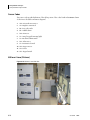
Inlet Unit Pictures
This chapter contains pictures of the Inlet Unit, Inlet Unit Transfer Arm, Inlet Unit Conveyor and
the associated diagram.
Figure 5.1 Inlet Unit
A64192AA2
FINAL
5-1
Inlet Unit
Inlet Unit Pictures
Figure 5.2 Inlet Unit Transfer Arm
Figure 5.3 Inlet Unit Conveyor
5-2
A64192AA2
FINAL
Figure 5.4 Inlet Unit Sensor Codes
LH 1500 HEMATOLOGY AUTOMATION SYSTEM
Inlet Unit
A641922AA2
5-3
Inlet Unit
Inlet Unit Pictures
Sensor Codes
The sensor codes provide definitions of the alpha portion of the codes found in the Sensor column
of the Error Code tables and Sensor diagrams.
1. AM = AC synchronous motor
2. AS = Magnetic autoswitch
3. BR = Bar-code reader
4. BZ = Audible alarm
5. DM = DC motor
6. LP = Lamp (keypad & warning light)
7. LS = Mechanical limit switch
8. PM = Pulse motor
9. SL = Pneumatic solenoid
10. SM = Stepper motor
11. SN = Sensor
12. SW = Keypad switch
5-4
A64192AA2
FINAL
CHAPTER 6
Connection Unit
Connection Unit Error Recovery
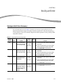
The Connection Unit Error Code Table 6.1 describes error messages generated by the LH 1500
Hematology Automation System. The table provides the system error codes, the related sensor, a
location reference point on the schematic diagram and a brief explanation of the possible problem
and possible solutions.
Table 6.1 Connection Unit Error Codes
Keypad
Display
1-01
Sensora
Problem
SN01
Obstruction or
hardware error at lower
limit sensor on the
Cassette Loading Arm.
Sensor
Diagram
Grid
Ref
Connection
Unit
Loading and
Unloading
Arms
D-5
Solution
1. Clear any obstruction.
2. If there is no obstruction:
a. SHUTDOWN at Line Controller and Power
OFF automation line at Inlet Unit.
b. Power ON the automation line at Inlet
Unit.
c. Perform STARTUP at Line Controller.
3. If the problem persists, call your Beckman
Coulter Representative.
1-02
SN02
Obstruction or
hardware error at the
middle limit sensor on
the Cassette Loading
Arm.
Connection
Unit
Loading and
Unloading
Arms
C-5
1. Clear any obstruction.
2. If there is no obstruction:
a. SHUTDOWN at Line Controller and Power
OFF automation line at Inlet Unit.
b. Power ON the automation line at Inlet
Unit.
c. Perform STARTUP at Line Controller.
3. If the problem persists, call your Beckman
Coulter Representative.
A64192AA2
FINAL
6-1
Connection Unit
Connection Unit Error Recovery
Table 6.1 Connection Unit Error Codes (Continued)
Keypad
Display
1-03
Sensora
SN03
Problem
Obstruction or
hardware error at the
upper limit sensor on
the Cassette Loading
Arm.
Sensor
Diagram
Grid
Ref
Connection
Unit
Loading and
Unloading
Arms
B-5
Solution
1. Clear any obstruction.
2. If there is no obstruction:
a. SHUTDOWN at Line Controller and Power
OFF automation line at Inlet Unit.
b. Power ON the automation line at Inlet
Unit.
c. Perform STARTUP at Line Controller.
3. If the problem persists, call your Beckman
Coulter Representative.
1-04
SN04
Obstruction or
hardware error at the
lower limit sensor on
the Cassette Unloading
Arm.
Connection
Unit
Loading and
Unloading
Arms
D-2
1. Clear any obstruction.
2. If there is no obstruction:
a. SHUTDOWN at Line Controller and Power
OFF automation line at Inlet Unit.
b. Power ON the automation line at Inlet
Unit.
c. Perform Startup at Line Controller.
3. If the problem persists, call your Beckman
Coulter Representative.
1-05
SN05
Obstruction or
hardware error at the
middle limit sensor on
the Cassette Unloading
Arm.
Connection
Unit
Loading and
Unloading
Arms
C-2
1. Clear any obstruction.
2. If there is no obstruction:
a. SHUTDOWN at Line Controller and Power
OFF automation line at Inlet Unit.
b. Power ON the automation line at Inlet
Unit.
c. Perform STARTUP at Line Controller.
3. If the problem persists, call your Beckman
Coulter Representative.
1-06
SN06
Obstruction or
hardware error at the
upper limit sensor on
the Cassette Unloading
Arm.
Connection
Unit
Loading and
Unloading
Arms
B-2
1. Clear any obstruction.
2. If there is no obstruction:
a. SHUTDOWN at Line Controller and Power
OFF automation line at Inlet Unit.
b. Power ON the automation line at Inlet
Unit.
c. Perform STARTUP at Line Controller.
3. If the problem persists, call your Beckman
Coulter Representative.
1-21
6-2
SN21
Sample Table Loading
Arm at the home
position did not
initialize due to an
obstruction or hardware
failure.
Connection
Unit Top
View
D-7
1. Clear any obstruction.
2. Press PAUSE/RUN to clear the error.
3. If the problem persists, call your Beckman
Coulter Representative.
A64192AA2
FINAL
Connection Unit
Connection Unit Error Recovery
Table 6.1 Connection Unit Error Codes (Continued)
Keypad
Display
Sensor
Diagram
Grid
Ref
Sample Tube Loading
Arm at the near home
position did not
initialize due to an
obstruction or hardware
failure.
Connection
Unit Top
View
D-7
1. Clear any obstruction.
2. Press PAUSE/RUN to clear the error.
3. If the problem persists, call your Beckman
Coulter Representative.
SN23
Sample Tube Loading
Arm at the limit position
did not initialize due to
an obstruction or
hardware failure.
Connection
Unit Top
View
D-6
1. Clear any obstruction.
2. Press PAUSE/RUN to clear the error.
3. If the problem persists, call your Beckman
Coulter Representative.
SN24
Scenarios:
Connection
Unit Top
View
D-4
1. Press PAUSE/RUN to clear the error.
2. If the problem persists:
a. Open the right-side tabletop safety cover.
b. Ensure there is no obstruction (cassette
trapped at shuttle position #5 or cassette
did not load onto Loading Arm).
c. Clear any obstruction if possible.
Sensora
Problem
1-22
SN22
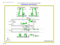
1-23
1-24
1. Leading edge of
cassette is not
detected in time at
cassette load
position #5
(cassette was
trapped).
2. Cassette is
incorrectly detected
at sensor 24 (due to
cassette not loading
onto Cassette
Loading Arm,
cassette was left on
track).
Solution
3. If there is no obstruction and cassette is in
position #5,
a. Manually load cassette onto Loading Arm
in proper finger position (cassette
positions 1 and 5).
b. Replace the right-side tabletop safety
cover.
c. Press PAUSE/RUN to clear the error.
4. If unable to remove trapped cassette:
a. Perform SHUTDOWN at Line Controller
b. Power OFF the automation line at Inlet
Unit.
c. Cut off incoming lab air supply to the line.
(If June-air compressor, turn Red Valve in
back of Compressor Unit.
d. Manually depress air cylinder (SL02) and
then remove trapped cassette.
e. Reconnect air supply.
f. Power ON the automation line at Inlet
Unit.
g. Perform STARTUP at Line Controller.
5. If the problem persists, call your Beckman
Coulter Representative.
A64192AA2
FINAL
6-3
6
Connection Unit
Connection Unit Error Recovery
Table 6.1 Connection Unit Error Codes (Continued)
Keypad
Display
1-25
Sensora
SN25
Problem
Scenario:
1. Unanalyzed
cassette may be in
cassette load
position #5 of the
shuttle and is
blocking sensor
SN25.
2. There may be an
obstruction
blocking sensor
SN25 before or after
a cassette is loaded
at position #5.
Sensor SN25 should
point to sample
tube position #2 in
the cassette
1-26
SN26
Cassette in shuttle has
not moved from
cassette position #5 to
position #6.
Sensor
Diagram
Grid
Ref
Connection
Unit Top
View
D-4
Solution
1. Press PAUSE/RUN to clear the error.
2. If the problem persists:
a. Open the left side bottom safety cover.
b. Ensure there is no obstruction (cassette
trapped at shuttle position #5 or cassette
did not load onto Loading Arm).
c. Clear any obstruction if possible.
d. Replace covers and press PAUSE/RUN to
clear the error.
3. If the problem persists, call your Beckman
Coulter Representative.
Connection
Unit Top
View
D-2
1. Press PAUSE/RUN to clear the error.
2. If the problem persists:
a. Open the left side bottom safety cover.
b. Ensure there is no obstruction (cassette
trapped at shuttle position #5 or cassette
did not load onto Loading Arm).
c. Clear any obstruction if possible.
d. Move cassette to position #6 in the
shuttle.
e. Replace cover and press PAUSE/RUN to
clear the error
3. If the problem persists, call your Beckman
Coulter Representative.
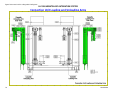
1-27
6-4
SN27
Sensor SN27 of the
Unload Shuttle is not
blocked by the
unloading cassette as
expected. (Cassette not
properly picked up from
Analyzer's left side
unloading bay and
placed at Unload
Shuttle cassette
position #7.)
Connection
Unit Top
View
C-1/
D-1
1. Remove Unloading Arm Cover from the leftside of Connection Unit.
2. Block SN27 with yardstick so that the sensor
light turns Green.
3. While blocking, the sensor light is Green.
4. Press PAUSE/RUN to clear the error.
5. If followed by Error Code 1-33:
a. Place proper cassette inside Connection
Unit at position #1.
b. Press PAUSE/RUN to clear the error.
A64192AA2
FINAL
Connection Unit
Connection Unit Error Recovery
Table 6.1 Connection Unit Error Codes (Continued)
Keypad
Display
1-28
1-29
1-30
1-31
1-32
A64192AA2
Sensor
Diagram
Grid
Ref
One of two limit sensors
associated with
cylinder SL25. Unload
Cassette Shuttle at
position #8.
Connection
Unit Top
View
C-1
One of two limit sensors
associated with
cylinder SL25. Unload
Cassette Shuttle at
position #7.
Connection
Unit Top
View
D-1
One of two limit sensors
associated with
cylinder SL26 at
position #8 at the Left
Side Unload Cassette
Shuttle.
Connection
Unit Top
View
C-2
One of two limit sensors
associated with
cylinder SL26 at
position #8 at the Left
Side Unload Cassette
Shuttle.
Connection
Unit Top
View
C-1
Analyzed cassette is in
cassette position #1.
SN32 should point to
sample tube position
#2 in the cassette.
Connection
Unit Top
View
C-4
Sensora
Problem
SN28
SN29
SN30
SN31
SN32
FINAL
Solution
This error occurs during Power ON, if the sensor
is defective.
1. Press PAUSE/RUN to clear the error.
2. If the problem persists, call your Beckman
Coulter Representative.
This error occurs during Power ON, if the sensor
is defective.
1. Press PAUSE/RUN to clear the error.
2. If the problem persists, call your Beckman
Coulter Representative.
This error occurs during Power ON, if the sensor
is defective.
1. Press PAUSE/RUN to clear the error.
2. If the problem persists, call your Beckman
Coulter Representative.
This error occurs during Power ON, if the sensor
is defective.
1. Press PAUSE/RUN to clear the error.
2. If the problem persists, call your Beckman
Coulter Representative.
This error occurs during Power ON, if the sensor
is defective.
1. Press PAUSE/RUN to clear the error.
2. If the problem persists, call your Beckman
Coulter Representative.
6-5
6
Connection Unit
Connection Unit Error Recovery
Table 6.1 Connection Unit Error Codes (Continued)
Keypad
Display
1-33
Sensora
SN33
Problem
Scenario:
1. Leading edge of
cassette was not
detected by sensor
SN33 at cassette
position #1.
2. Cassette trapped by
Stopper cylinder
SL27 at cassette
position #1.
Sensor
Diagram
Grid
Ref
Connection
Unit Top
View
C-5
Solution
1. Press PAUSE/RUN to clear the error.
2. If the problem persists:
a. Open the right-side tabletop safety cover.
b. Ensure there is no obstruction in path of
cassette. (1).
c. Clear any obstruction if possible.
d. Replace the right-side tabletop safety
cover.
e. Press PAUSE/RUN to clear the error.
3. If unable to remove trapped cassette: (2)
a. Perform SHUTDOWN at Line Controller.
b. Power OFF automation line at Inlet Unit.
c. Cut off incoming lab air supply to the line.
(If June-air compressor, turn Red Valve in
back of Compressor Unit.)
d. Manually depress air cylinder (SL27) and
then remove trapped cassette.
e. Reconnect air supply.
f. Power ON the automation line at Inlet
Unit.
g. Perform STARTUP at Line Controller.
4. If the problem persists, call your Beckman
Coulter Representative.
6-6
1-34
SN34
Sample Tube Unloading
Arm in the home
position did not
initialize due to an
obstruction or hardware
failure.
Connection
Unit Top
View
C-7
1. Clear any obstruction.
2. Press PAUSE/RUN to clear the error.
3. If the problem persists, call your Beckman
Coulter Representative.
1-35
SN35
Sample Tube Unloading
Arm in the near home
position did not
initialize due to an
obstruction or hardware
failure.
Connection
Unit Top
View
C-7
1. Clear any obstruction.
2. Press PAUSE/RUN to clear the error.
3. If the problem persists, call your Beckman
Coulter Representative.
1-36
SN36
Sample tube Unloading
Arm in the limit position
did not initialize due to
an obstruction or
hardware failure.
Connection
Unit Top
View
C-5
1. Clear any obstruction.
2. Press PAUSE/RUN to clear the error.
3. If the problem persists, call your Beckman
Coulter Representative.
A64192AA2
FINAL
Connection Unit
Connection Unit Error Recovery
Table 6.1 Connection Unit Error Codes (Continued)
Keypad
Display
1-37
Sensora
SN37
Problem
Scenarios:
1. Cassette was not
detected inside the
Load Shuttle
cassette position
#3.
2. Cassette incorrectly
detected inside
Load Shuttle during
Startup.
1-38
1-39
1-40
SN38
SN39
SN40
Sensor
Diagram
Grid
Ref
Connection
Unit Top
View
D-7
Solution
1. If error occurs when cassette is pushed into
the Load Shuttle:
a. Open the right-side tabletop safety cover.
b. Slide cassette to the right so the SN37
Orange LED is ON.
c. Replace the right-side tabletop safety
cover.
d. Press PAUSE/RUN to clear the error.
2. If the problem occurs immediately after
Startup:
a. Open the right-side tabletop safety cover.
b. Remove cassette from inside the Load
Shuttle cassette position #3.
c. Replace the right-side tabletop safety
cover.
One of two limit sensors
associated with
cylinder SL28 Right
Side Load Cassette
Shuttle, position #3.
Connection
Unit Top
View
D-7
One of two limit sensors
associated with
cylinder SL28 Right
Side Load Cassette
Shuttle, position #4.
Connection
Unit Top
View
C-7
Problem associated
with moving the
cassette in and out of
cassette position #2
(Tube pushup and
unload area).
Connection
Unit Top
View
C-6
This error occurs during Power On, if the sensor is
defective.
If the problem persists, call your Beckman
Coulter Representative.
This error occurs during Power On, if the sensor is
defective.
If the problem persists, call your Beckman
Coulter Representative.
1. Press PAUSE/RUN to clear the error.
2. If the problem persists:
a. Open the right-side tabletop safety cover.
b. Ensure the cassette has traveled from
cassette position #1 to cassette position
#2.
c. Ensure the Tube Unloading Arm finger is
trying to engage the cassette in order to
move it.
3. If the problem persist,
a. When the cassette has already moved to
position #2 and the Load Shuttle is at the
back position #3, then move the cassette
to position #3.
b. Replace the right-side tabletop safety
cover and press PAUSE/RUN to clear the
error.
4. If the problem continues to persist, call your
Beckman Coulter Representative.
A64192AA2
FINAL
6-7
6
Connection Unit
Connection Unit Error Recovery
Table 6.1 Connection Unit Error Codes (Continued)
Keypad
Display
1-41
Sensora
SN41
Problem
Scenarios:
1. Fiber optic sensor
did not detect a
sample tube at
Connection Unit
bar-code reader cup
(BR01) after
attempting to insert
a tube in the cup.
2. Fiber optic sensor
incorrectly detected
a sample tube left
at Connection Unit
bar-code reader cup
(BR01) after
unloading the tube.
1-42
1-43
SN43
Grid
Ref
Connection
Unit Side
View
C-4
Solution
1. Ensure whether a sample tube is present at
bar-code reader BR01.
2. If there is no sample tube located at BR01, (1)
a. Locate the sample tube in the Loading
Elevator.
b. Place sample tube in front of BR01.
c. Press PAUSE/RUN to clear the error.
3. If there is a sample tube located at BR01, (2)
a. Remove sample tube in front of BR01.
b. Press PAUSE/RUN to clear the error.
4. If followed by Error Code 1-49:
a. Place sample tube in cassette directly in
front of sensor. 1-49 with the label facing
towards the rear of the instrument.
b. Press PAUSE/RUN to clear the error.
One of two limits
sensors for the Loading
Elevator cylinder SL49,
(down sensor error).
Connection
Unit Side
View
D-5
One of two limits
sensors for the Loading
Elevator cylinder SL49
(up sensor error).
Connection
Unit Side
View
D-6
This error occurs during Power On, if the sensor is
defective.
1. Press PAUSE/RUN to clear the error.
2. If the problem persists, call your Beckman
Coulter Representative.
This error occurs during Power On if the sensor is
defective.
1. Press PAUSE/RUN to clear the error.
2. If the problem persists, call your Beckman
Coulter Representative.
1-44
SN44
Fiber optic sensor did
not detect a sample
tube at the lower
position of the
Unloading Elevator.
Connection
Unit Side
View
C-5
1. Ensure sample tube was loaded into
Unloading Elevator sample tube carrier.
2. Press PAUSE/RUN to clear the error.
3. If the problem persists, call your Beckman
Coulter Representative.
1-45
SN45
One of two limits
sensors for the
Unloading Elevator
cylinder SL51 (down
sensor error)
Connection
Unit Side
View
D-5
This error occurs during Power On, if the sensor is
defective.
One of two limits
sensors for the
Unloading Elevator
cylinder SL51 (up
sensor error)
Connection
Unit Side
View
D-6
1-46
6-8
SN42
Sensor
Diagram
SN46
1. Press PAUSE/RUN to clear the error.
2. If the problem persists, call your Beckman
Coulter Representative.
This error occurs during Power On, if the sensor is
defective.
1. Press PAUSE/RUN to clear the error.
2. If the problem persists, call your Beckman
Coulter Representative.
A64192AA2
FINAL
Connection Unit
Connection Unit Error Recovery
Table 6.1 Connection Unit Error Codes (Continued)
Keypad
Display
Sensora
Problem
Sensor
Diagram
Grid
Ref
Solution
1-47
SN47
Connection
Safety cover over the
Unit
Right-side Cassette
Loading Arm was off or Loading and
not properly positioned. Unloading
Arms
A-5
1. Ensure Loading Arm safety cover on the right
is properly positioned so that the sensor's
Red LED is ON.
2. Press PAUSE/RUN to clear the error.
1-48
SN48
Safety cover over the
Left-side Cassette
Unloading Arm was off
or not properly
positioned.
Connection
Unit
Loading and
Unloading
Arms
A-2
1. Ensure Unloading Arm safety cover on the
left-side is properly positioned so that the
sensor's Red LED is ON.
2. Press PAUSE/RUN to clear the error.
1-49
SN49
Fiber optic sensor did
not detect the sample
tube being loaded by
the Sample Tube
Loading Arm at the
following locations:
Connection
Unit Side
View
C-3
1. Locate the missing sample tube in either the
loading elevator or in front of BR01.
2. Locate fiber optic sensor 1-49 and place the
sample tube directly in front of sensor 1-49 in
either:
a. the sample tube holder next to BR01,
or
b. the cassette in position #4 with the label
facing towards the rear of the instrument
(depending on location of fiber optic
sensor 1-49.)
1. Loading Elevator
sample carrier
when it's down
inside the
Connection pickup
point.
2. When inserting
tubes in the
cassette at position
#4 of the Cassette
Handling
mechanism.
3. Press PAUSE/RUN to clear the error.
1-50
SN50
Fiber optic sensor
detected a sample tube
was left in the cassette
by the Sample Tube
Unloading Arm.
Connection
Unit Side
View
C-2
1. Locate sample tube in the cassette in front of
fiber optic sensor (SN50).
2. Remove the sample tube.
3. Press PAUSE/RUN to clear the error.
4. If followed by Error Code 1-44:
a. Place the sample tube in the unloading
elevator sample tube holder beside
SN44.
b. Press PAUSE/RUN to clear the error.
1-61
SN61
Sample tube carrier
error in the area in front
of the Conveyor Lane
bar-code reader BR02.
Connection
Unit
Conveyor
D-4
1. Clear any obstruction.
2. If a sample tube carrier is jammed, gently
twist and push the sample tube carrier in the
direction of least resistance.
3. Press PAUSE/RUN to clear the error.
A64192AA2
FINAL
6-9
6
Connection Unit
Connection Unit Error Recovery
Table 6.1 Connection Unit Error Codes (Continued)
Keypad
Display
Sensor
Diagram
Grid
Ref
Sample tube carrier
error in the area in front
of the Conveyor Lane
bar-code reader BR02
Connection
Unit
Conveyor
D-4
1. Clear any obstruction.
2. If a sample tube carrier is jammed, gently
twist and push the sample tube carrier in the
direction of least resistance.
3. Press PAUSE/RUN to clear the error.
SN65
Proximity sensor SN65
did not detect in time
the arrival of the
sample tube carrier,
located before the
Conveyor Loading Arm.
Connection
Unit
Conveyor
C-4
1. Clear any obstruction.
2. Press PAUSE/RUN to clear the error.
1-66
SN66
Proximity sensor SN66
did not detect in time
the arrival of the
sample tube carrier,
located at the Conveyor
Loading Arm.
Connection
Unit
Conveyor
D-4
1. Clear any obstruction.
2. If a sample tube carrier is jammed, gently
twist and push the sample tube carrier in the
direction of least resistance.
3. Press PAUSE/RUN to clear the error.
1-67
SN67
Fiber optic sensor
detected a sample tube
was left in the sample
tube carrier, located at
the Conveyor Loading
Arm.
Connection
Unit
Conveyor
D-4
1. Place the sample tube into the Loading
Elevator.
2. Press PAUSE/RUN to clear the error.
1-68
SN68
Proximity sensor SN68
did not detect the
arrival of the tube
carrier that had just left
the Loading Arm area.
Connection
Unit
Conveyor
D-4
1. Clear any obstruction.
2. If a sample tube carrier is jammed, gently
twist and push the sample tube carrier in the
direction of least resistance.
3. Press PAUSE/RUN to clear the error.
1-69
SN69
Fiber optic sensor
detects that a tube was
not off-loaded from the
Unloading Elevator.
Connection
Unit
Conveyor
B-4
1. Locate the sample tube and place in the
sample tube carrier next to SN69.
2. Press PAUSE/RUN to clear the error.
1-70
SN70
Proximity sensor SN70
error indicates the
expected sample tube
carrier did not arrived in
the allotted time.
Connection
Unit
Conveyor
D-5
1. Press PAUSE/RUN to clear the error.
2. If the problem persists:
a. Place a metal object in front of sensor
1-70.
b. Press PAUSE/RUN to clear the error.
1-71
SN71
One of two limit sensors
for the Conveyor
Loading Arm cylinder
SL72.
Connection
Unit
Conveyor
C-3
This error occurs during Power On, if the sensor is
defective.
Sensora
Problem
1-62
SN62
1-65
6-10
Solution
1. Press PAUSE/RUN to clear the error.
2. If the problem persists, call your Beckman
Coulter Representative.
A64192AA2
FINAL
Connection Unit
Connection Unit Error Recovery
Table 6.1 Connection Unit Error Codes (Continued)
Keypad
Display
1-72
1-73
1-74
Sensor
Diagram
Grid
Ref
One of two limit sensors
for the Conveyor
Loading Arm cylinder
SL72.
Connection
Unit
Conveyor
C-3
One of two limit sensors
for the Conveyor
Loading Arm cylinder
SL74.
Connection
Unit
Conveyor
C-5
One of two limit sensors
for the Conveyor
Loading Arm cylinder
SL74.
Connection
Unit
Conveyor
C-5
Sensora
Problem
SN72
SN73
SN74
Solution
This error occurs during Power On, if the sensor is
defective.
1. Press PAUSE/RUN to clear the error.
2. If the problem persists, call your Beckman
Coulter Representative.
This error occurs during Power On, if the sensor is
defective.
1. Press PAUSE/RUN to clear the error.
2. If the problem persists, call your Beckman
Coulter Representative.
This error occurs during Power On, if the sensor is
defective.
1. Press PAUSE/RUN to clear the error.
2. If the problem persists, call your Beckman
Coulter Representative.
1-75
SN75
Sample tube carrier
error at Conveyor
Unloading Arm
indicates the expected
tube carrier did not
arrive in the allotted
time.
Connection
Unit
Conveyor
B-4
1. Clear any obstruction.
2. Ensure a sample tube carrier is available to
off load the waiting sample tube.
3. Press PAUSE/RUN to clear the error.
2-01
SL01
Connection
During its operation
Unit
Cassette Loading Arm
Loading and
cylinder SL01 did not
fully extend and misses Unloading
Arms
activating the limit
sensor. The two limit
sensors are AS01
(down) and AS02 (up).
B-7
1. Ensure the cassette loading arm fingers align
with sample tube positions #1 and #5 of the
cassette and the positions are empty.
2. Press PAUSE/RUN to clear the error.
3. If the problem persists, call your Beckman
Coulter Representative.
2-02
SL02
Connection
During its operation
Unit
Cassette Loading Arm
Loading and
cylinder SL02 did not
fully extend and misses Unloading
Arms
activating the limit
sensor. The two limit
sensors for SL02 are
AS03 (down) and AS04
(up).
B-7
1. Ensure the cassette loading arm fingers align
with sample tube positions #1 and #5 of the
cassette and the positions are empty.
2. Press PAUSE/RUN to clear the error.
3. If the problem persists, call your Beckman
Coulter Representative.
A64192AA2
FINAL
6-11
6
Connection Unit
Connection Unit Error Recovery
Table 6.1 Connection Unit Error Codes (Continued)
Keypad
Display
Sensora
Problem
Sensor
Diagram
Grid
Ref
Solution
2-03
SL03
During its operation
Cassette Loading Arm
cylinder SL03 did not
swing up/down and
misses activating the
limit sensor. The two
limit sensors for SL03
are AS06 (down) and
AS05 (up).
Connection
Unit
Loading and
Unloading
Arms
B-7
1. Clear any obstruction.
2. Ensure cassette is properly seated on loading
arm fingers.
3. Press PAUSE/RUN to clear the error.
4. If the problem persists, call your Beckman
Coulter Representative.
2-04
SL04
During its operation
Cassette Unloading
Arm cylinder SL04 did
not fully extend and
misses activating the
limit sensor. The two
limit sensors are AS07
(down) and AS08 (up).
Connection
Unit
Loading and
Unloading
Arms
B/C-1
1. Ensure the cassette loading arm fingers align
with sample tube positions #8 and #12 of the
cassette and the positions are empty.
2. Press PAUSE/RUN to clear the error.
3. If the problem persists, call your Beckman
Coulter Representative.
2-05
SL05
During its operation
Cassette Unloading
Arm cylinder SL05 did
not fully extend and
misses activating the
limit sensor. The two
limit sensors are AS09
(down) and AS10 (up).
Connection
Unit
Loading and
Unloading
Arms
B-1
1. Ensure the cassette loading arm fingers align
with sample tube positions #8 and #12 of the
cassette and the positions are empty.
2. Press PAUSE/RUN to clear the error.
3. If the problem persists, call your Beckman
Coulter Representative.
2-06
SL06
During its operation
Cassette Unloading
Arm cylinder SL06 did
not swing up/down and
misses activating the
limit sensor. The two
limit sensors are AS12
(down) and AS11 (up.)
Connection
Unit
Loading and
Unloading
Arms
B-1
1. Clear any obstruction.
2. Ensure cassette is properly seated on loading
arm fingers.
3. Press PAUSE/RUN to clear the error.
4. If the problem persists, call your Beckman
Coulter Representative.
6-12
A64192AA2
FINAL
Connection Unit
Connection Unit Error Recovery
Table 6.1 Connection Unit Error Codes (Continued)
Keypad
Display
2-21
Sensora
SL21
Problem
Cassette jam was
detected in cassette
load position #5.
Cassette could be
jammed by Stopper
cylinder SL21.
Sensor
Diagram
Grid
Ref
Connection
Unit Top
View
C-4
Solution
1. Press PAUSE/RUN to clear the error.
2. If the problem persists:
a. Open the right-side tabletop safety cover.
b. Ensure cassette is not trapped by Stopper
cylinder SL21 at shuttle position #5.
3. If unable to remove trapped cassette:
a. Perform SHUTDOWN at Line Controller.
b. Power OFF automation line at Inlet Unit.
c. Cut off incoming lab air supply to the line.
(If June-air compressor, turn Red Valve in
back of Compressor Unit).
d. Manually depress air cylinder (SL21) and
then remove trapped cassette.
e. Reposition the cassette in position #5.
f. Reconnect air supply.
g. Power ON the automation line at Inlet
Unit.
h. Perform STARTUP at Line Controller.
4. If the problem persists, call your Beckman
Coulter Representative.
2-22
SL22
Cassette may be
jammed between
cassette position #6
and cassette position
#7.
Connection
Unit Top
View
D-3
1. Open the left lower front cover.
2. Clear any obstructions if possible.
3. Remove jammed cassette and place into
cassette position #7.
4. Replace covers.
5. Press PAUSE/RUN to clear the error.
6. If unable to remove trapped cassette”
a. Perform SHUTDOWN at Line Controller.
b. Power OFF automation line at Inlet Unit.
c. Cut off incoming lab air supply to the line.
(If June-air compressor, turn Red Valve in
back of Compressor Unit.)
d. Manually depress air cylinder (SL22) and
then remove trapped cassette.
e. Reposition the cassette in position #6.
f. Reconnect air supply.
g. Power ON the automation line at Inlet
Unit.
h. Perform STARTUP at Line Controller.
7. If the problem persists, call your Beckman
Coulter Representative.
A64192AA2
FINAL
6-13
6
Connection Unit
Connection Unit Error Recovery
Table 6.1 Connection Unit Error Codes (Continued)
Keypad
Display
2-23
Sensora
Problem
SL23
Stopped cassette error
at cassette position #6.
Cassette could be
jammed.
Sensor
Diagram
Grid
Ref
Connection
Unit Top
View
D-2
Solution
1. Open the left lower front cover.
2. Ensure cassette is properly positioned at
cassette position #6.
3. Replace covers.
4. Press PAUSE/RUN to clear the error.
If unable to remove trapped cassette”
a. Perform SHUTDOWN at Line Controller.
b. Power OFF automation line at Inlet Unit.
c. Cut off incoming lab air supply to the line.
(If June-air compressor, turn Red Valve in
back of Compressor Unit.)
d. Manually depress air cylinder (SL23) and
then remove trapped cassette.
e. Reposition the cassette in position #6.
f. Reconnect air supply.
g. Power ON the automation line at Inlet
Unit.
h. Perform STARTUP at Line Controller.
5. lf recovery is not possible, call your Beckman
Coulter Representative.
2-24
SL24
The analyzed cassette
is held at cassette
position #7 in the Left
Side Cassette Shuttle.
The Cassette Unloading
Arm cannot release the
cassette.
Connection
Unit Top
View
D-2
1. Press PAUSE/RUN to clear the error.
If arm cannot release cassette:
a. Open the left lower front cover.
b. Press down on the cassette to ensure
cassette releases from Cassette
Unloading Arm.
c. Replace covers.
d. Press PAUSE/RUN to clear the error.
2. If recovery is not possible, call your Beckman
Coulter Representative.
2-25
6-14
SL25
Left Side Cassette
Unload Shuttle
movement is
obstructed.
Connection
Unit Top
View
C/D-2
1.
2.
3.
4.
5.
Open the left lower front cover.
Clear any obstructions.
Replace covers.
Press PAUSE/RUN to clear the error.
If the problem persists, call your Beckman
Coulter Representative.
A64192AA2
FINAL
Connection Unit
Connection Unit Error Recovery
Table 6.1 Connection Unit Error Codes (Continued)
Keypad
Display
Sensor
Diagram
Grid
Ref
Cassette Ejector
cylinder SL26 did not
fully extend and misses
activating the limit
sensor. The cassette did
not move from shuttle
position #8. Cassette
could be jammed. The
two limit sensors are
SN30 and SN31.
Connection
Unit Top
View
C-1/2
1. Open the left lower front cover.
2. Clear obstruction or cause for jamming of the
cassette ejector.
3. Replace covers.
4. Press PAUSE/RUN to clear the error.
5. If the problem persists, call your Beckman
Coulter Representative.
Cassette Stopper
cylinder SL27 may have
trapped the cassette at
cassette position #1.
Connection
Unit Top
View
C-5
1. Press PAUSE/RUN to clear the error.
2. If the problem persists:
a. Open the right-side tabletop safety cover.
b. Ensure there is no obstruction (cassette
trapped by Stopper at shuttle position
#1).
c. Clear any obstructions if possible.
d. Replace the right-side tabletop safety
cover.
e. Press PAUSE/RUN to clear the error.
Sensora
Problem
2-26
SL26
2-27
SL27
Solution
3. If unable to remove trapped cassette:
a. Perform SHUTDOWN at Line Controller
b. Power OFF automation line at Inlet Unit.
c. Cut off incoming lab air supply to the line.
(If June-air compressor, turn Red Valve in
back of Compressor Unit).
d. Open the right-side tabletop safety cover.
e. Manually depress air cylinder (SL27) and
then remove trapped cassette.
f. Reconnect air supply.
g. Replace covers.
h. Power ON the automation line at Inlet
Unit.
i. Perform STARTUP at Line Controller.
4. If the problem persists, call your Beckman
Coulter Representative.
2-28
A64192AA2
SL28
FINAL
Right Side Cassette
Shuttle Load
movement is
obstructed.
Connection
Unit Top
View
C/D-7
1.
2.
3.
4.
5.
Open the left lower front cover.
Clear any obstructions.
Replace covers.
Press PAUSE/RUN to clear the error.
If the problem persists, call your Beckman
Coulter Representative.
6-15
6
Connection Unit
Connection Unit Error Recovery
Table 6.1 Connection Unit Error Codes (Continued)
Keypad
Display
2-41
Sensora
Problem
SL41
Sample Tube Loading
Arm cylinder did not
extend / retract
properly and misses
activating the limit
sensor. Cassette may
be misaligned. The limit
sensors are AS41
(down) and AS42 (up).
Sensor
Diagram
Grid
Ref
Connection
Unit Side
View
B-3
Solution
1. Press PAUSE/RUN to clear the error
2. If the problem persists,:
a. Ensure proper alignment of cassette
position #12 and SL41 finger.
b. Clear any obstruction if possible.
c. Replace covers.
d. Ensure proper alignment of cassette
position #12 and SL41.
e. Clear obstruction if possible.
f. Press PAUSE/RUN to clear the error.
3. If the problem persists, call your Beckman
Coulter Representative.
2-42
SL42
Sample Tube Loading
Arm cylinder SL42 did
not fully extend / retract
and was unable to
activate its limit sensor.
The sample tube
gripper may have tried
to insert another
sample tube into a
cassette that already
contains a sample tube.
The limit sensors are
AS43 (up) and AS44
(down).
Connection
Unit Side
View
C-3
1. Open the right-side tabletop safety cover.
2. Ensure cassette at loading position #4 is fully
seated to the right in the cassette shuttle.
3. Ensure alignment of the sample tube in the
Sample Tube Loading Arm gripper fingers and
the cassette position immediately in front of
SN49.
4. Replace covers.
5. Press PAUSE/RUN to clear the error.
6. If the problem persists, call your Beckman
Coulter Representative.
2-44
SL44
Sample Tube Unloading
Arm cylinder SL44 did
not fully extend / retract
and was unable to
activate its limit sensor.
Sample Tube Unloading
Arm gripper error
removing the sample
tubes from cassette to
the Unloading Elevator.
The limit sensors are
AS46 (up) and AS45
(down).
Connection
Unit Side
View
B-2
1. Open the right-side tabletop safety cover.
2. Ensure cassette is aligned at unloading
position #3.
3. Ensure alignment of the sample tube in the
Sample Tube Unloading Arm gripper fingers
and the cassette position immediately in
front of SN50.
4. Replace covers.
5. Press PAUSE/RUN to clear the error.
6. If the problem persists, call your Beckman
Coulter Representative.
6-16
A64192AA2
FINAL
Connection Unit
Connection Unit Error Recovery
Table 6.1 Connection Unit Error Codes (Continued)
Keypad
Display
2-45
Sensora
Problem
SL45
Sample Tube Unloading
Arm cylinder SL45 did
not fully extend / retract
and was unable to
activate its limit sensor.
The limit sensors are
AS48 (up) and AS47
(down).
Sensor
Diagram
Grid
Ref
Connection
Unit Side
View
C-2
Solution
1. Press PAUSE/RUN to clear the error.
2. If the problem persists:
a. Open the right-side tabletop safety cover.
b. Ensure proper cassette alignment or clear
any obstructions.
c. Replace covers.
d. Press PAUSE/RUN to clear the error.
3. If the problem persists, call your Beckman
Coulter Representative.
2-47
SL47
Sample tube(s) pusher
cylinder SL47 did not
fully extend and misses
activating its limit
sensor. It may not be
able to push tubes up to
unload them from
cassette. The limit
sensors are AS49 (up)
and AS50 (down).
Connection
Unit Side
View
D-2
1. Press PAUSE/RUN to clear the error.
2. If the problem persists:
a. Open the right-side tabletop safety cover.
b. Ensure there are not too many labels on a
tube not allowing tubes to be pushed up
to unload.
c. Ensure proper cassette alignment or clear
any obstruction.
d. Replace covers.
e. Press PAUSE/RUN to clear the error.
3. If the problem persists, call your Beckman
Coulter Representative.
2-48
2-49
A64192AA2
SL48
SL49
FINAL
Vertical Load Elevator
cylinder SL48 did not
fully extend / retract
and misses activating
its limit sensor. The
error occurs as the
loading holder moves
the sample tube carrier
up or down. The limit
sensors are AS51 (up)
and AS52 (down).
Connection
Unit Side
View
Loading Elevator
cylinder SL49 did not
fully extend / retract as
the loading holder
moved the sample up
or down and misses
activating its limit
sensor. The limit
sensors are SN42
(down) and SN43 (up).
Connection
Unit Side
View
D-5
1. Press PAUSE/RUN to clear the error.
2. If loading elevator does not move up or down:
a. Look into the Conveyor cover hole for the
Elevator carrier.
b. Verify there are no obstructions in the
path of the Elevator carrier.
c. Press PAUSE/RUN to clear the error.
3. If the problem persists, call your Beckman
Coulter Representative.
6-17
6
Connection Unit
Connection Unit Error Recovery
Table 6.1 Connection Unit Error Codes (Continued)
Keypad
Display
2-50
2-51
Sensor
Diagram
Grid
Ref
Vertical Unload Elevator
cylinder SL50 did not
fully extend / retract
and miss activating its
limit sensor. The errors
occur as the loading
holder moves the
sample tube carrier up
or down. The limit
sensors are AS53 (up)
and AS54 (down).
Connection
Unit Side
View
D-5
Loading Elevator
cylinder SL49 did not
fully extend / retract as
the loading holder
moved the sample up
or down and misses
activating its limit
sensor. The limit
sensors are SN45
(down) and SN46 (up).
Connection
Unit Side
View
Sensora
Problem
SL50
SL51
Solution
1. Press PAUSE/RUN to clear the error.
2. If loading elevator does not move up or down:
a. Look into the Conveyor cover hole for the
Elevator carrier.
b. Verify there are no obstructions in the
path of the Elevator carrier.
c. Press PAUSE/RUN to clear the error.
3. If the problem persists, call your Beckman
Coulter Representative.
D-5
1. Press PAUSE/RUN to clear the error.
2. If loading elevator does not move up or down:
a. Clear any obstruction.
b. Press PAUSE/RUN to clear the error.
3. If the problem persists, call your Beckman
Coulter Representative.
2-61
SL61
Stopper error before
the Conveyor Lane barcode reader BR02.
Connection
Unit
Conveyor
D-4
1. Clear any obstruction.
2. If a sample tube carrier is jammed, gently
twist and push the sample tube carrier in the
direction of least resistance.
3. Press PAUSE/RUN to clear the error.
2-62
SL62
Stopper error before
the Conveyor Lane barcode reader BR02.
Connection
Unit
Conveyor
D-4
1. Clear any obstruction.
2. If a sample tube carrier is jammed, gently
twist and push the sample tube carrier in the
direction of least resistance.
3. Press PAUSE/RUN to clear the error.
2-63
SL63
Stopper error at the
Conveyor Lane barcode reader BR02.
Connection
Unit
Conveyor
D-4
1. Clear any obstruction.
2. If a sample tube carrier is jammed, gently
twist and push the sample tube carrier in the
direction of least resistance.
3. Press PAUSE/RUN to clear the error.
2-64
SL64
Divider Arm error
diverting a sample tube
carrier to the Conveyor
Loading Arm.
Connection
Unit
Conveyor
D-4
1. Ensure the Divider Arm is free to extend and
retract.
2. Ensure the Divider arm is not slow to extend
or retract. If so, the flow of air may have to be
adjusted.
3. Press PAUSE/RUN to clear the error.
4. If the problem persists, call your Beckman
Coulter Representative.
Associated with limit
sensors AS64
(retracted) and AS74
(extended).
6-18
A64192AA2
FINAL
Connection Unit
Connection Unit Error Recovery
Table 6.1 Connection Unit Error Codes (Continued)
Keypad
Display
Sensora
Problem
Sensor
Diagram
Grid
Ref
2-65
SL65
Stopper error at
Conveyor Loading Arm
point "a".
Connection
Unit
Conveyor
D-4
a
1. Clear any obstruction.
2. If a sample tube carrier is jammed, gently
twist and push the sample tube carrier in the
direction of least resistance.
3. Press PAUSE/RUN to clear the error.
2-66
SL66
Stopper error at
Conveyor Loading Arm
point "b".
Connection
Unit
Conveyor
D-4
b
1. Clear any obstruction.
2. If a sample tube carrier is jammed, gently
twist and push the sample tube carrier in the
direction of least resistance.
3. Press PAUSE/RUN to clear the error.
2-67
SL67
Stopper error before
Conveyor Unloading
Arm.
Connection
Unit
Conveyor
C-4
1. Clear any obstruction.
2. If a sample tube carrier is jammed, gently
twist and push the sample tube carrier in the
direction of least resistance.
3. Press PAUSE/RUN to clear the error.
2-68
SL68
Stopper error at
Conveyor Unloading
Arm.
Connection
Unit
Conveyor
C-4
1. Clear any obstruction.
2. if a sample tube carrier is jammed, gently
twist and push the sample tube carrier in the
direction of least resistance.
3. Press PAUSE/RUN to clear the error.
2-69
SL69
Divider Arm error
diverting the sample
carrier with an offloaded sample tube
from the Connection
Unit to the conveyor on
the main lane.
Associated with AS69
(retracted) and AS75
(extended).
Connection D-5
Unit
Conveyor
1. Ensure the Divider Arm is free to extend and
retract.
2. Ensure the Divider arm is not slow to extend
or retract. If so, the flow of air may have to be
adjusted.
3. Press PAUSE/RUN to clear the error.
4. If the problem persists, call your Beckman
Coulter Representative.
2-70
SL70
Conveyor Loading Arm
did not fully extend /
retract while loading
tubes onto the Elevator
Sample Carrier and
misses activating its
limit sensor. The limit
sensors are AS70 (up)
and AS71 (down).
Connection C-3
Unit
Conveyor
1. Clear any obstruction.
2. Press PAUSE/RUN to clear the error.
3. If the problem persists, call your Beckman
Coulter Representative.
A64192AA2
FINAL
Solution
6-19
6
Connection Unit
Connection Unit Error Recovery
Table 6.1 Connection Unit Error Codes (Continued)
Keypad
Display
Sensor
Diagram
Grid
Ref
Sensora
Problem
2-71
SL71
Conveyor Loading Arm
rotary cylinder SL71
error while swinging
between the sample
tube pick up pick-up
position or the Loading
Elevator position. The
rotary cylinder limit
sensors are SN71 and
SN72.
Connection C-3
Unit
Conveyor
1. Clear any obstruction.
2. Press PAUSE/RUN to clear the error.
3. If the problem persists, call your Beckman
Coulter Representative.
2-73
SL73
Conveyor Unloading
Arm cylinder SL73 did
not fully extend / retract
while unloading tubes
from the Unload
Elevator Sample Carrier
and misses activating
its limit sensor. The limit
sensors are AS72 (up)
and AS73 (down).
Connection C-5
Unit
Conveyor
1. Clear any obstruction.
2. Press PAUSE/RUN to clear the error.
3. If the problem persists, call your Beckman
Coulter Representative.
2-74
SL74
Conveyor Unloading
Arm rotary cylinder
SL74 error while
swinging between the
unload sample tube
carrier position and the
Unloading Elevator
position. The rotary
cylinder limit sensors
SN73 and SN74.
Connection C-5
Unit
Conveyor
1. Clear any obstruction.
2. Press PAUSE/RUN to clear the error.
3. If the problem persists, call your Beckman
Coulter Representative.
3-01
BR01
Failure of the Bar-code
reader BR01. May have
lost programming.
Connection D-8
Unit Top
View
1. Perform SHUTDOWN at Line Controller.
2. Enter the System Setup > Maintenance
menu.
Default Password=password1
3. Verify correct setting of bar-code label and
exit screen.
Upon exiting the screen the bar-code readers
will be reprogrammed.
4. If the problem persists, call your Beckman
Coulter Representative.
6-20
Solution
A64192AA2
FINAL
Connection Unit
Connection Unit Error Recovery
Table 6.1 Connection Unit Error Codes (Continued)
Keypad
Display
Sensor
Diagram
Grid
Ref
Sensora
Problem
3-02
BR02
Failure of the Bar-code
reader BR02. May have
lost programming.
Connection D-4
Unit
Conveyor
1. Perform SHUTDOWN at Line Controller.
2. Enter the System Setup > Maintenance
menu.
Default Password=password1
3. Verify correct setting of bar-code label and
exit screen.
Upon exiting the screen the bar-code readers
will be reprogrammed.
4. If the problem persists, call your Beckman
Coulter Representative.
4-01
PM01
Pulse Motor PM01 Error
driving the Sample
Tube Loading Arm.
Connection D-5
Unit Top
View
1. Open the right-side tabletop safety cover.
2. Manually move the Sample Tube Loading
Arm approximately 1 foot to the left.
3. Replace the right-side tabletop safety cover.
4. Press PAUSE/RUN to clear the error.
4-02
PM02
Pulse Motor PM02 Error
driving the Sample
Tube Unloading Arm.
Connection C-4
Unit Top
View
1. Open the right-side tabletop safety cover.
2. Manually move the Sample Tube Loading
Arm approximately 1 foot to the left.
3. Replace the right-side tabletop safety cover.
4. Press PAUSE/RUN to clear the error.
5-01
LH01
COM
Parallel communication
error with the Analyzer:
Cassette is ready to be
loaded. The Analyzer
did not issue load
permission.
Connection None
Unit
1. Ensure the LH 750 is operational and ready to
receive cassette.
Analyzer may be unable to accept another
cassette due to workload, reagent change or
lengthy delay.
2. Press PAUSE/RUN to clear the error.
5-02
LH02
TIM
Time out error at
Analyzer while in STATCASS mode. Cassette
Loading/Unloading Arm
covers open beyond set
time.
Connection None
Unit
1. Ensure the STAT-CASS mode of analysis is
completed.
2. Ensure the Loading and Unloading Arm
safety covers are replaced and STAT-CASS
mode is deselected.
3. Press PAUSE/RUN to clear the error.
5-03
LH03
RACK
Improper cassette(s)
located in the LH 750
Unloading Bay.
Connection None
Unit
1. Remove improper cassette(s) from
LH 750 Unloading Bay.
2. Press PAUSE/RUN to clear the error.
5-04
LH04 IN
Analyzer cassette
delivery error: The
LH 750 Analyzer
received a cassette, but
it was not loaded
correctly.
Connection None
Unit
1. Ensure the cassette is loaded properly in the
LH 750 Loading Bay.
OR
2. Ensure the cassette sensor on the
LH 750 Analyzer is functioning properly.
3. Press PAUSE/RUN to clear the error.
A64192AA2
FINAL
Solution
6-21
6
Connection Unit
Connection Unit Error Recovery
Table 6.1 Connection Unit Error Codes (Continued)
Keypad
Display
9-01
9-02
Sensora
AM01
AM02
Problem
Sensor
Diagram
Grid
Ref
Solution
AC Synchronous Motor Connection D-5
Unit
Failure while driving the
Cassette Loading Arm Loading and
Unloading
up or down.
Arms
There is no user procedure to solve this problem.
Connection D-3
Unit
Loading and
Unloading
Arms
There is no user procedure to solve this problem.
AC Synchronous Motor
Failure driving the
Cassette Unloading
Arm.
Call your Beckman Coulter Representative.
Call your Beckman Coulter Representative.
a. See Abbreviations for a list of sensor codes.
6-22
A64192AA2
FINAL
CHAPTER 7
Connection Unit Conveyor
Connection Unit Conveyor Pictures
This chapter contains pictures of the Connection Unit Conveyor, Connection Unit Loading and
Unloading Arms, Connection Unit Side View, Connection Unit Top and the associated diagrams.
Figure 7.1 Connection Unit Conveyor Side View
A64192AA2
FINAL
7-1
Connection Unit Conveyor
Connection Unit Conveyor Pictures
Figure 7.2 Connection Unit Conveyor Top View
7-2
A64192AA2
FINAL
Figure 7.3 Connection Unit Conveyor
LH 1500 HEMATOLOGY AUTOMATION SYSTEM
Connection Unit Conveyor
A641922AA2
7-3
Connection Unit Conveyor
Connection Unit Conveyor Pictures
Sensor Codes
The sensor codes provide definitions of the alpha portion of the codes found in the Sensor column
of the Error Code tables and Sensor diagrams.
1. AM = AC synchronous motor
2. AS = Magnetic autoswitch
3. BR = Bar-code reader
4. BZ = Audible alarm
5. DM = DC motor
6. LP = Lamp (keypad & warning light)
7. LS = Mechanical limit switch
8. PM = Pulse motor
9. SL = Pneumatic solenoid
10. SM = Stepper motor
11. SN = Sensor
12. SW = Keypad switch
Connection Unit Loading and Unloading Arms (Pictures)
Figure 7.4 Connection Unit Overall View
7-4
A64192AA2
FINAL
Connection Unit Conveyor
Connection Unit Conveyor Pictures
Figure 7.5 Connection Unit Loading and Unloading Arms
A64192AA2
FINAL
7-5
7
Figure 7.6 Connection Unit Loading and Unloading Arms
LH 1500 HEMATOLOGY AUTOMATION SYSTEM
Connection Unit Loading and Unloading Arms
7-6
A641922AA2
Connection Unit Conveyor
Connection Unit Conveyor Pictures
Sensor Codes:
The sensor codes provide definitions of the alpha portion of the codes found in the Sensor column
of the Error Code tables and Sensor diagrams.
1. AM = AC synchronous motor
2. AS = Magnetic autoswitch
3. BR = Bar-code reader
4. BZ = Audible alarm
5. DM = DC motor
6. LP = Lamp (keypad & warning light)
7. LS = Mechanical limit switch
8. PM = Pulse motor
9. SL = Pneumatic solenoid
10. SM = Stepper motor
11. SN = Sensor
12. SW = Keypad switch
Connection Unit Side View (Pictures)
Figure 7.7 Connection Unit Overall View
A64192AA2
FINAL
7-7
7
Connection Unit Conveyor
Connection Unit Conveyor Pictures
Figure 7.8 Connection Unit Side View
7-8
A64192AA2
FINAL
Figure 7.9 Connection Unit Side View
LH 1500 HEMATOLOGY AUTOMATION SYSTEM
Connection Unit Side View
A641922AA2
7-9
Connection Unit Conveyor
Connection Unit Conveyor Pictures
Sensor Codes:
The sensor codes provide definitions of the alpha portion of the codes found in the Sensor column
of the Error Code tables and Sensor diagrams.
1. AM = AC synchronous motor
2. AS = Magnetic autoswitch
3. BR = Bar-code reader
4. BZ = Audible alarm
5. DM = DC motor
6. LP = Lamp (keypad & warning light)
7. LS = Mechanical limit switch
8. PM = Pulse motor
9. SL = Pneumatic solenoid
10. SM = Stepper motor
11. SN = Sensor
12. SW = Keypad switch
Connection Unit Top View (Pictures)
Figure 7.10 Connection Unit Overall View
7-10
A64192AA2
FINAL
Connection Unit Conveyor
Connection Unit Conveyor Pictures
Figure 7.11 Connection Unit Top View
A64192AA2
FINAL
7-11
7
Figure 7.12 Connection Unit Top Diagram
LH 1500 HEMATOLOGY AUTOMATION SYSTEM
Connection Unit Top View
7-12
A641922AA2
Connection Unit Conveyor
Connection Unit Conveyor Pictures
Sensor Codes:
The sensor codes provide definitions of the alpha portion of the codes found in the Sensor column
of the Error Code tables and Sensor diagrams.
1. AM = AC synchronous motor
2. AS = Magnetic autoswitch
3. BR = Bar-code reader
4. BZ = Audible alarm
5. DM = DC motor
6. LP = Lamp (keypad & warning light)
7. LS = Mechanical limit switch
8. PM = Pulse motor
9. SL = Pneumatic solenoid
10. SM = Stepper motor
11. SN = Sensor
12. SW = Keypad switch
A64192AA2
FINAL
7-13
7
Connection Unit Conveyor
Connection Unit Conveyor Pictures
7-14
A64192AA2
FINAL
CHAPTER 8
Stockyard Unit
Stockyard Unit Error Recovery
The Stockyard Unit Error Code Table 8.1 describes error messages generated by the LH 1500
Hematology Automation System. The table provides the system error codes, the related sensor, a
location reference point on the schematic diagram and a brief explanation of the possible problem
and possible solutions.
Table 8.1 Stockyard Unit Error Recovery Codes
Keypad
Display
Sensora
Problem
0-00
BZ00
0-11
0-12
0-13
A64192AA2
BZ11
BZ12
BZ13
FINAL
Sensor
Diagram
Grid
Ref
Bar-code label did not
read at the Stockyard
bar-code reader BR01.
Stockyard
Unit
D-3
1. Ensure the bar-code is present and properly
positioned.
2. Turn the sample tube in the carrier at BR01
with bar-code facing the bar-code reader.
3. Press PAUSE/RUN to clear the error.
Bar-code label did not
read at the Stockyard
bar-code reader BR01.
Stockyard
Unit
D-3
1. Ensure the bar-code is present and properly
positioned.
2. Turn the sample tube in the carrier at BR01
with bar-code facing the bar-code reader.
3. Press PAUSE/RUN to clear the error.
Positioning error at the
Stockyard bar-code
reader BR01.
Stockyard
Unit
D-3
1. Ensure the bar-code is present and properly
positioned.
2. Turn the sample tube in the carrier at BR01
with bar-code facing the bar-code reader.
3. Press PAUSE/RUN to clear the error.
Invalid routing code at
the Stockyard bar-code
reader BR01. Additional
sample programming
caused a sorting
conflict.
Stockyard
Unit
D-3
1. Remove the sample tube and press ENTER.
2. Press PAUSE/RUN to clear the error.
Conveyor
Conveyor
Conveyor
Solution
Conveyor
8-1
Stockyard Unit
Stockyard Unit Error Recovery
Table 8.1 Stockyard Unit Error Recovery Codes (Continued)
Keypad
Display
Sensora
0-21
BZ21
Problem
Stockyard bar-code
reader error at BR02.
Sensor
Diagram
Grid
Ref
Stockyard
Unit
D-4
1. Ensure the bar-code is present and properly
positioned.
2. Turn the sample tube in the carrier at BR01
with bar-code facing the bar-code reader.
3. Press PAUSE/RUN to clear the error.
D-4
1. Ensure the bar-code is present and properly
positioned.
2. Turn the sample tube in the carrier at BR01
with bar-code facing the bar-code reader.
3. Press PAUSE/RUN to clear the error.
D-4
1. Remove the sample tube.
2. Press PAUSE/RUN to clear the error.
Conveyor
0-22
0-23
1-04
1-05
1-21
1-22
1-32
1-33
8-2
BZ22
BZ23
SN04
SN05
SN21
SN22
SN32
SN33
Positioning error at the
Stockyard bar-code
reader BR02.
Stockyard
Unit
Invalid route code at
the Stockyard bar-code
reader BR02. Additional
sample programming
caused a sorting
conflict.
Stockyard
Unit
Sample tube not
present in the first level
Stockyard Loading
Shuttle Cup.
3000 Tube
Stockyard
Sample tube not
present in the first level
Stockyard Retrieving
Shuttle Cup.
3000 Tube
Stockyard
Sample tube not
present in the second
level Stockyard Loading
Shuttle Cup.
3000 Tube
Stockyard
Sample tube not
present in the second
level Stockyard
Retrieving Shuttle Cup.
3000 Tube
Stockyard
Sample tube not
present in the third
level Stockyard Loading
Shuttle Cup.
3000 Tube
Stockyard
Sample tube not
present in the third
level Stockyard
Retrieving Shuttle Cup.
3000 Tube
Stockyard
Conveyor
Solution
Conveyor
E-4/5
C
1. Ensure sample tube is correctly loaded into
Stockyard Loading Shuttle Cup.
2. Press PAUSE/RUN to clear the error.
E-4/5
C
1. Ensure sample tube is correctly loaded into
Stockyard Loading Shuttle Cup.
2. Press PAUSE/RUN to clear the error.
E-4/5
C
1. Ensure sample tube is correctly loaded into
Stockyard Loading Shuttle Cup.
2. Press PAUSE/RUN to clear the error.
E-4/5
C
1. Ensure sample tube is correctly loaded into
Stockyard Loading Shuttle Cup.
2. Press PAUSE/RUN to clear the error.
E-4/5
C
1. Ensure sample tube is correctly loaded into
Stockyard Loading Shuttle Cup.
2. Press PAUSE/RUN to clear the error.
E-4/5
C
1. Ensure sample tube is correctly loaded into
Stockyard Loading Shuttle Cup.
2. Press PAUSE/RUN to clear the error.
Top View
Top View
Top View
Top View
Top View
Top View
A64192AA2
FINAL
Stockyard Unit
Stockyard Unit Error Recovery
Table 8.1 Stockyard Unit Error Recovery Codes (Continued)
Keypad
Display
Sensora
1-40
SN40
1-43
1-44
1-45
1-46
1-48
1-49
A64192AA2
SN43
SN44
SN45
SN46
SN48
SN49
FINAL
Sensor
Diagram
Grid
Ref
Sample tube carrier
error before the
Stockyard bar-code
reader BR01.
Stockyard
Unit
D-3
1. Ensure the sensor is operating correctly.
2. If a sample tube carrier is jammed, gently
twist and push the sample tube carrier in the
direction of least resistance.
3. Press PAUSE/RUN to clear the error.
Sample tube carrier
error before the
Stockyard bar-code
reader BR01.
Stockyard
Unit
D-3
1. Clear any obstruction.
2. If a sample tube carrier is jammed, gently
twist and push the sample tube carrier in the
direction of least resistance.
3. Press PAUSE/RUN to clear the error.
Fiber Optic sensor is
detecting incorrectly
the tube on the sample
carrier. Stockyard
Loading Arm gripper
failed to pick up sample
at Bar-code reader
BR01
Stockyard
Unit
D-3
1. Remove the sample tube from the sample
tube holder in front of SN44 and place the
sample tube in the Stockyard Loading Arm
gripper fingers.
2. Press PAUSE/RUN to continue.
Sample tube carrier
error before the
Stockyard bar-code
reader BR02.
Stockyard
Unit
Sample tube carrier
error before the
Stockyard bar-code
reader BR02.
Stockyard
Unit
Sample tube carrier
error at the Stockyard
bar-code reader BR02.
Stockyard
Unit
Fiber optic sensor did
not detect a sample
tube at the Stockyard
bar-code reader BR02
during a retrieval
process.
Stockyard
Unit
Problem
Conveyor
Conveyor
Conveyor
Solution
NOTE DO NOT place the sample tube in the
sample tube holder below the Stockyard
Loading Arm gripper. This may cause the
Stockyard Loading Arm to bend, or cause
sample tube breakage.
D-4
1. Clear any obstruction.
2. If a sample tube carrier is jammed, gently
twist and push the sample tube carrier in the
direction of least resistance.
3. Press PAUSE/RUN to clear the error.
D-4
1. Clear any obstruction.
2. If a sample tube carrier is jammed, gently
twist and push the sample tube carrier in the
direction of least resistance.
3. Press PAUSE/RUN to clear the error.
D-4
1. Clear any obstruction.
2. If a sample tube carrier is jammed, gently
twist and push the sample tube carrier in the
direction of least resistance.
3. Press PAUSE/RUN to clear the error.
D-4
1. Ensure the sample tube was retrieved from
the Retrieving Shuttle Cup.
2. Press PAUSE/RUN to clear the error.
Conveyor
Conveyor
Conveyor
Conveyor
8-3
8
Stockyard Unit
Stockyard Unit Error Recovery
Table 8.1 Stockyard Unit Error Recovery Codes (Continued)
Keypad
Display
Sensora
Problem
1-51
SN51
1-52
8-4
SN52
Sensor
Diagram
Grid
Ref
Proximity sensor did not
detect the expected
sample tube carrier
after it passed BR02.
Stockyard
Unit
D-5
1. Clear any obstruction.
2. If a sample tube carrier is jammed, gently
twist and push the sample tube carrier in the
direction of least resistance.
3. Press PAUSE/RUN to clear the error.
Sample tube carrier
error at the Stockyard
waiting sample tube
carrier queue.
Stockyard
Unit
D/E-4
1. Clear any obstruction.
2. If a sample tube carrier is jammed, gently
twist and push the sample tube carrier in the
direction of least resistance.
3. Press PAUSE/RUN to clear the error.
Conveyor
Conveyor
Solution
1-55
SN55
Sample tube carrier
Stockyard
error before the H-Lane. Unit T Lane
C-3
1. Clear any obstruction.
2. If a sample tube carrier is jammed, gently
twist and push the sample tube carrier in the
direction of least resistance.
3. Press PAUSE/RUN to clear the error.
1-57
SN57
Sample tube carrier
error at the T-Lane
sample tube carrier
sorting position #1.
Stockyard
Unit T Lane
C-4
1. Clear any obstruction.
2. If a sample tube carrier is jammed, gently
twist and push the sample tube carrier in the
direction of least resistance.
3. Press PAUSE/RUN to clear the error.
1-58
SN58
Proximity sensor did not
detect a sample tube
carrier after it entered
the H-Lane.
Stockyard
Unit T Lane
C-3/4
1. Clear any obstruction.
2. If a sample tube carrier is jammed, gently
twist and push the sample tube carrier in the
direction of least resistance.
3. Press PAUSE/RUN to clear the error.
1-59
SN59
Sample tube carrier
error on the exit of the
H-Lane.
Stockyard
Unit T Lane
C-4
1. Clear any obstruction.
2. If a sample tube carrier is jammed, gently
twist and push the sample tube carrier in the
direction of least resistance.
3. Press PAUSE/RUN to clear the error.
1-60
SN60
Sample tube carrier
error at the T-Lane
sample tube carrier
sorting position #2.
Stockyard
Unit T Lane
C-4
1. Clear any obstruction.
2. If a sample tube carrier is jammed, gently
twist and push the sample tube carrier in the
direction of least resistance.
3. Press PAUSE/RUN to clear the error.
1-62
SN62
Proximity sensor did not
detect a sample tube
carrier arriving
Stockyard waiting
empty sample tube
carrier queue.
Stockyard
Unit T Lane
C-4
1. Clear any obstruction.
2. If a sample tube carrier is jammed, gently
twist and push the sample tube carrier in the
direction of least resistance.
3. Press PAUSE/RUN to clear the error.
A64192AA2
FINAL
Stockyard Unit
Stockyard Unit Error Recovery
Table 8.1 Stockyard Unit Error Recovery Codes (Continued)
Keypad
Display
Sensora
Problem
1-63
SN63
1-64
Sensor
Diagram
Grid
Ref
Proximity sensor did not
detect a sample tube
carrier on return lane.
Stockyard
Unit T Lane
D--4
1. Clear any obstruction.
2. If a sample tube carrier is jammed, gently
twist and push the sample tube carrier in the
direction of least resistance.
3. Press PAUSE/RUN to clear the error.
SN64
Sample tube carrier
error coming from HLane incoming lane to
make the turn to the
return lane.
Stockyard
Unit H Lane
B-4
1. Clear any obstruction.
2. If a sample tube carrier is jammed, gently
twist and push the sample tube carrier in the
direction of least resistance.
3. Press PAUSE/RUN to clear the error.
1-65
SN65
Proximity sensor did not
detect a sample tube
carrier turning on HLane.
Stockyard
Unit H Lane
B-4
1. Clear any obstruction.
2. If a sample tube carrier is jammed, gently
twist and push the sample tube carrier in the
direction of least resistance.
3. Press PAUSE/RUN to clear the error.
1-67
SN67
Stockyard first level
access door open.
3000 Tube
Stockyard
C-4/5
1. Close the door.
2. Press PAUSE/RUN to clear the error.
3. If the error persists, call your Beckman
Coulter Representative.
C-4/5
1. Close the door.
2. Press PAUSE/RUN to clear the error.
3. If the error purists, call your Beckman Coulter
Representative.
C-4/5
1. Close the door.
2. Press PAUSE/RUN to clear the error.
3. If the error purists, call your Beckman Coulter
Representative.
E-4/5
C
1. Ensure the Stockyard Loading Shuttle
movement is not obstructed.
2. Press PAUSE/RUN to clear the error.
E-4/5
C
1. Ensure the Stockyard Retrieving Shuttle
movement is not obstructed.
2. Press PAUSE/RUN to clear the error.
D-4/5
D
1. Ensure the Stockyard Internal Transfer Arm
air cylinder movement is not obstructed.
2. Press PAUSE/RUN to clear the error.
D-4/5
D
1. Ensure that Stockyard Internal Arm Pushing
cylinder movement is not obstructed.
2. Press PAUSE/RUN to clear the error.
Top View
1-68
SN68
Stockyard second level
access door open.
3000 Tube
Stockyard
Top View
1-69
SN69
Stockyard third level
access door open.
3000 Tube
Stockyard
Top View
2-01
2-02
2-03
2-05
A64192AA2
SL01
SL02
SL03
SL05
FINAL
Stockyard Loading
Shuttle Cup error on
first level.
3000 Tube
Stockyard
Stockyard Retrieving
Shuttle Cup error on
first level.
3000 Tube
Stockyard
Stockyard Internal
Transfer Arm air
cylinder error on first
level moving up or
down.
3000 Tube
Stockyard
Stockyard Internal Arm
Pushing cylinder error
on the first level.
3000 Tube
Stockyard
Top View
Top View
Top View
Top View
Solution
8-5
8
Stockyard Unit
Stockyard Unit Error Recovery
Table 8.1 Stockyard Unit Error Recovery Codes (Continued)
Keypad
Display
Sensora
Problem
2-06
SL06
2-08
2-10
2-11
2-12
2-14
2-15
2-16
2-17
2-19
2-40
8-6
SL08
SL10
SL11
SL12
SL14
SL15
SL16
SL17
SL19
SL40
Sensor
Diagram
Grid
Ref
Rotating cylinder error
on the Stockyard
Loading Elevator.
3000 Tube
Stockyard
E-4
A
1. Ensure the Stockyard Loading Elevator
movement is not obstructed.
2. Press PAUSE/RUN to clear the error.
Rotating cylinder error
on the Stockyard
Retrieving Elevator.
3000 Tube
Stockyard
E-5
B
1. Ensure the Stockyard Retrieving Elevator
movement is not obstructed.
2. Press PAUSE/RUN to clear the error.
Stockyard Loading
Shuttle Cup error on
second level.
3000 Tube
Stockyard
Stockyard Retrieving
Shuttle Cup error on
second level.
3000 Tube
Stockyard
Stockyard Internal
Transfer Arm air
cylinder error on
second level moving up
or down.
3000 Tube
Stockyard
Stockyard Internal Arm
Pushing cylinder error
on the second level.
3000 Tube
Stockyard
Stockyard Loading
Shuttle Cup error on
third level.
3000 Tube
Stockyard
Stockyard Retrieving
Shuttle Cup error on
third level.
3000 Tube
Stockyard
Stockyard Internal
Transfer Arm cylinder
error on third level
moving up or down.
3000 Tube
Stockyard
Stockyard Internal Arm
Pushing cylinder error
on the third level.
3000 Tube
Stockyard
Stopper error before
the Stockyard bar-code
reader BR01.
Stockyard
Top View
Top View
E-4/5
C
1. Ensure the Stockyard Loading Shuttle
movement is not obstructed.
2. Press PAUSE/RUN to clear the error.
E-4/5
C
1. Ensure the Stockyard Retrieving Shuttle
movement is not obstructed.
2. Press PAUSE/RUN to clear the error.
D-4/5
D
1. Ensure the Stockyard Internal Transfer Arm
air cylinder movement is not obstructed.
2. Press PAUSE/RUN to clear the error.
D-4/5
D
1. Ensure that Stockyard Internal Arm Pushing
cylinder movement is not obstructed.
2. Press PAUSE/RUN to clear the error.
E-4/5
C
1. Ensure the Stockyard Loading Shuttle
movement is not obstructed.
2. Press PAUSE/RUN to clear the error.
E-4/5
C
1. Ensure the Stockyard Retrieving Shuttle
movement is not obstructed.
2. Press PAUSE/RUN to clear the error.
D-4/5
D
1. Ensure the Stockyard Internal Transfer Arm
cylinder movement is not obstructed.
2. Press PAUSE/RUN to clear the error.
D-4/5
D
1. Ensure that Stockyard Internal Arm Pushing
cylinder movement is not obstructed.
2. Press PAUSE/RUN to clear the error.
D-3
1. Clear any obstruction.
2. If a sample tube carrier is jammed, gently
twist and push the sample tube carrier in the
direction of least resistance.
3. Press PAUSE/RUN to clear the error.
Top View
Top View
Top View
Top View
Top View
Top View
Top View
Top View
Unit
Conveyor
Solution
A64192AA2
FINAL
Stockyard Unit
Stockyard Unit Error Recovery
Table 8.1 Stockyard Unit Error Recovery Codes (Continued)
Keypad
Display
Sensora
Problem
2-41
SL41
2-43
2-44
2-45
2-46
2-48
2-49
2-50
A64192AA2
SL43
SL44
SL45
SL46
SL48
SL49
SL50
FINAL
Sensor
Diagram
Grid
Ref
Stopper error before
the Stockyard bar-code
reader BR01.
Stockyard
D-3
1. Clear any obstruction.
2. If a sample tube carrier is jammed, gently
twist and push the sample tube carrier in the
direction of least resistance.
3. Press PAUSE/RUN to clear the error.
Stopper error at the
Stockyard bar-code
reader BR01.
Stockyard
D-3
1. Clear any obstruction.
2. If a sample tube carrier is jammed, gently
twist and push the sample tube carrier in the
direction of least resistance.
3. Press PAUSE/RUN to clear the error.
Stopper error at the
second stopper before
the Stockyard bar-code
reader BR02.
Stockyard
D-4
1. Clear any obstruction.
2. If a sample tube carrier is jammed, gently
twist and push the sample tube carrier in the
direction of least resistance.
3. Press PAUSE/RUN to clear the error.
Stopper error at the
stopper before the
Stockyard bar-code
reader BR02.
Stockyard
D-4
1. Clear any obstruction.
2. If a sample tube carrier is jammed, gently
twist and push the sample tube carrier in the
direction of least resistance.
3. Press PAUSE/RUN to clear the error.
Stopper error at the
Stockyard bar-code
reader BR02.
Stockyard
D-4
1. Clear any obstruction.
2. If a sample tube carrier is jammed, gently
twist and push the sample tube carrier in the
direction of least resistance.
3. Press PAUSE/RUN to clear the error.
Stopper error at the
Stockyard waiting
empty sample tube
carrier queue.
Stockyard
E-4
1. Clear any obstruction.
2. If a sample tube carrier is jammed, gently
twist and push the sample tube carrier in the
direction of least resistance.
3. Press PAUSE/RUN to clear the error.
Stopper error at the
Stockyard waiting
empty sample tube
carrier queue.
Stockyard
E-4
1. Clear any obstruction.
2. If a sample tube carrier is jammed, gently
twist and push the sample tube carrier in the
direction of least resistance.
3. Press PAUSE/RUN to clear the error.
Stockyard Divider Arm
error at the sample
tube carrier waiting
lane sorting position.
Stockyard
D-4
1. Ensure the gate is free to extend and retract.
2. Ensure the gate arm is not to slow to extend/
retract. If so, the cylinder air flow controller
may need adjustment.
3. Press PAUSE/RUN to clear the error.
Unit
Conveyor
Unit
Conveyor
Unit
Conveyor
Unit
Conveyor
Unit
Conveyor
Unit
Conveyor
Unit
Conveyor
Unit
Conveyor
Solution
8-7
8
Stockyard Unit
Stockyard Unit Error Recovery
Table 8.1 Stockyard Unit Error Recovery Codes (Continued)
Keypad
Display
Sensora
2-55
SL55
2-56
2-57
2-58
2-59
2-60
2-61
2-62
8-8
SL56
SL57
SL58
SL59
SL60
SL61
SL62
Problem
Stopper error at the
T-Lane before sorting
position.
Stopper error at the
T-Lane sorting position.
Stockyard Divider Arm
error at the entrance of
H Lane.
Stopper error at the exit
of the H-Lane.
Stopper error at the exit
of the H-Lane.
Stopper error at the TLane sample tube
carrier sorting position
#1.
Stopper error at the TLane sample tube
carrier sorting position
#2.
Stockyard Divider Arm
error at the T-Lane
sample tube carrier
sorting position #2.
Sensor
Diagram
Grid
Ref
Stockyard
C-3
1. Clear any obstruction.
2. If a sample tube carrier is jammed, gently
twist and push the sample tube carrier in the
direction of least resistance.
3. Press PAUSE/RUN to clear the error.
C-3
1. Clear any obstruction.
2. If a sample tube carrier is jammed, gently
twist and push the sample tube carrier in the
direction of least resistance.
3. Press PAUSE/RUN to clear the error.
C-3
1. Ensure the gate is free to extend and retract.
2. Ensure the gate arm is not to slow to extend/
retract. If so, the cylinder air flow controller
may need adjustment.
3. Press PAUSE/RUN to clear the error.
C-4
1. Clear any obstruction.
2. If a sample tube carrier is jammed, gently
twist and push the sample tube carrier in the
direction of least resistance.
3. Press PAUSE/RUN to clear the error.
C-4
1. Clear any obstruction.
2. If a sample tube carrier is jammed, gently
twist and push the sample tube carrier in the
direction of least resistance.
3. Press PAUSE/RUN to clear the error.
C-4
1. Clear any obstruction.
2. If a sample tube carrier is jammed, gently
twist and push the sample tube carrier in the
direction of least resistance.
3. Press PAUSE/RUN to clear the error.
C-4
1. Clear any obstruction.
2. If a sample tube carrier is jammed, gently
twist and push the sample tube carrier in the
direction of least resistance.
3. Press PAUSE/RUN to clear the error.
C-4
1. Ensure the gate is free to extend and retract.
2. Ensure the gate arm is not to slow to extend/
retract. If so, the cylinder air flow controller
may need adjustment.
3. Press PAUSE/RUN to clear the error.
Unit T Lane
Stockyard
Unit T Lane
Stockyard
Unit T Lane
Stockyard
Unit T Lane
Stockyard
Unit T Lane
Stockyard
Unit T Lane
Stockyard
Unit T Lane
Stockyard
Unit T Lane
Solution
A64192AA2
FINAL
Stockyard Unit
Stockyard Unit Error Recovery
Table 8.1 Stockyard Unit Error Recovery Codes (Continued)
Keypad
Display
Sensora
2-63
SL63
2-64
3-01
3-02
4-01
SL64
BR01
BR02
SM01
Problem
Stopper error at the
H-Lane empty sample
tube carrier lane.
Stopper error at the
H-Lane empty sample
tube carrier lane.
Sensor
Diagram
Grid
Ref
Stockyard
B-3/4
1. Clear any obstruction.
2. If a sample tube carrier is jammed, gently
twist and push the sample tube carrier in the
direction of least resistance.
3. Press PAUSE/RUN to clear the error.
B-3/4
1. Clear any obstruction.
2. If a sample tube carrier is jammed, gently
twist and push the sample tube carrier in the
direction of least resistance.
3. Press PAUSE/RUN to clear the error.
D-3
1. Perform SHUTDOWN at Line Controller.
2. Enter the System Setup, Maintenance
menu.
Default Password=password1
3. Verify correct setting of bar-code label and
exit screen.
Upon exiting the screen, the bar-code readers
will be reprogrammed.
4. If the problem persists, call your Beckman
Coulter Representative.
D-4
1. Perform SHUTDOWN at Line Controller.
2. Enter the System Setup, Maintenance
menu.
Default Password=password1
3. Verify correct setting of bar-code label and
exit screen.
Upon exiting the screen, the bar-code readers
will be reprogrammed.
4. If the problem persists, call your Beckman
Coulter Representative.
D-4/5
D
1. Ensure the Stockyard Transfer Arm
movement is not obstructed.
2. Press PAUSE/RUN to clear the error.
3. If there is no obstruction:
a. Power OFF Stockyard Unit, wait one
minute and then Power ON the Stockyard
Unit to reset.
b. Place Stockyard in AUTO mode to
initialize.
Unit H Lane
Stockyard
Unit H Lane
Failure of the Bar-code
reader BR01 to read.
May have lost its
programming.
Stockyard
Failure of the Bar-code
reader BR02 to read.
May have lost its
programming.
Stockyard
Failure to move the
Stockyard Transfer Arm
on the first level in the
X-axis direction.
3000 Tube
Stockyard
Top View
Unit
Conveyor
Unit
Conveyor
Solution
4. If the problem persists, call your Beckman
Coulter Representative.
A64192AA2
FINAL
8-9
8
Stockyard Unit
Stockyard Unit Error Recovery
Table 8.1 Stockyard Unit Error Recovery Codes (Continued)
Keypad
Display
Sensora
Problem
4-02
SM02
Failure to move the
Stockyard Transfer Arm
on the first level in the
Y-axis direction.
Sensor
Diagram
Grid
Ref
3000 Tube
Stockyard
Top View
C-4/5
Solution
1. Ensure the Stockyard Transfer Arm
movement is not obstructed.
2. Press PAUSE/RUN to clear the error.
3. If there is no obstruction:
a. Power OFF Stockyard Unit, wait one
minute and then Power ON the Stockyard
Unit to reset.
b. Place Stockyard in AUTO mode to
initialize.
4. If the problem persists, call your Beckman
Coulter Representative.
4-03
SM03
Failure to move the
Stockyard Loading
Elevator in the Z-axis
direction.
3000 Tube
Stockyard
Top View
E-4
A
1. Ensure the Stockyard Loading Elevator
movement is not obstructed.
2. Press PAUSE/RUN to clear the error.
3. If there is no obstruction:
a. Power OFF Stockyard Unit, wait one
minute and then Power ON the Stockyard
Unit to reset.
b. Place Stockyard in AUTO mode to
initialize.
4. If the problem persists, call your Beckman
Coulter Representative.
4-04
SM04
Failure to move the
Stockyard Retrieving
Elevator in the Z-axis
direction.
3000 Tube
Stockyard
Top View
E-5
B
1. Ensure the Stockyard Retrieving Elevator
movement is not obstructed.
2. Press PAUSE/RUN to clear the error.
3. If there is no obstruction:
a. Power OFF Stockyard Unit, wait one
minute and then Power ON the Stockyard
Unit to reset.
b. Place Stockyard in AUTO mode to
initialize.
4. If the problem persists, call your Beckman
Coulter Representative.
4-05
SM05
Failure to move the
Stockyard Transfer Arm
on the second level in
the X-axis direction.
3000 Tube
Stockyard
Top View
D-4/5
D
1. Ensure the Stockyard Transfer Arm
movement is not obstructed.
2. Press PAUSE/RUN to clear the error.
3. If there is no obstruction:
a. Power OFF Stockyard Unit, wait one
minute and then Power ON the Stockyard
Unit to reset.
b. Place Stockyard in AUTO mode to
initialize.
4. If the problem persists, call your Beckman
Coulter Representative.
8-10
A64192AA2
FINAL
Stockyard Unit
Stockyard Unit Error Recovery
Table 8.1 Stockyard Unit Error Recovery Codes (Continued)
Keypad
Display
Sensora
Problem
4-06
SM06
Failure to move the
Stockyard Transfer Arm
on the second level in
the Y-axis direction.
Sensor
Diagram
Grid
Ref
3000 Tube
Stockyard
Top View
C-4/5
Solution
1. Ensure the Stockyard Transfer Arm
movement is not obstructed.
2. Press PAUSE/RUN to clear the error.
3. If there is no obstruction:
a. Power OFF Stockyard Unit, wait one
minute and then Power ON the Stockyard
Unit to reset.
b. Place Stockyard in AUTO mode to
initialize.
4. If the problem persists, call your Beckman
Coulter Representative.
4-07
SM07
Failure to move the
Stockyard Transfer Arm
on the third level in the
X-axis direction.
3000 Tube
Stockyard
Top View
D-4/5
D
1. Ensure the Stockyard Transfer Arm
movement is not obstructed.
2. Press PAUSE/RUN to clear the error.
3. If there is no obstruction:
a. Power OFF Stockyard Unit, wait one
minute and then Power ON the Stockyard
Unit to reset.
b. Place Stockyard in AUTO mode to
initialize.
4. If the problem persists, call your Beckman
Coulter Representative.
4-08
SM08
Failure to move the
Stockyard Transfer Arm
on the third level in the
Y-axis direction.
3000 Tube
Stockyard
Top View
C-4/5
1. Ensure the Stockyard Transfer Arm
movement is not obstructed.
2. Press PAUSE/RUN to clear the error.
3. If there is no obstruction:
a. Power OFF Stockyard Unit, wait one
minute and then Power ON the Stockyard
Unit to reset.
b. Place Stockyard in AUTO mode to
initialize.
4. If the problem persists, call your Beckman
Coulter Representative.
7-07
A64192AA2
AS07
FINAL
Stockyard Internal
Transfer Arm gripper on
the first level failed to
pick up sample.
3000 Tube
Stockyard
Top View
D-4/5
D
1. Ensure the sample tube is properly
positioned in gripper fingers.
2. Press PAUSE/RUN to clear the error.
8-11
8
Stockyard Unit
Stockyard Unit Error Recovery
Table 8.1 Stockyard Unit Error Recovery Codes (Continued)
Keypad
Display
Sensora
Problem
7-22
AS22
7-31
AS31
Sensor
Diagram
Grid
Ref
Stockyard Internal
Transfer Arm gripper on
the second level failed
to pick up sample.
3000 Tube
Stockyard
Top View
D-4/5
D
1. Ensure the sample tube is properly
positioned in gripper fingers.
2. Press PAUSE/RUN to clear the error.
Stockyard Internal
Transfer Arm gripper on
the third level failed to
pick up sample.
3000 Tube
Stockyard
Top View
D-4/5
D
1. Ensure the sample tube is properly
positioned in gripper fingers.
2. Press PAUSE/RUN to clear the error.
Solution
a. See Abbreviations for a list of sensor codes.
8-12
A64192AA2
FINAL
CHAPTER 9
Stockyard Unit Conveyor
Stockyard Unit Conveyor Pictures
Figure 9.1 Stockyard Unit Overall Rear View
A64192AA2
FINAL
9-1
Stockyard Unit Conveyor
Stockyard Unit Conveyor Pictures
Figure 9.2 Stockyard Unit Conveyor Top View
9-2
A64192AA2
FINAL
Figure 9.3 Connection Unit Top Diagram
LH 1500 HEMATOLOGY AUTOMATION SYSTEM
Stockyard Unit Conveyor
A641922AA2
9-3
Stockyard Unit Conveyor
Stockyard Unit Conveyor Pictures
Sensor Codes
The sensor codes provide definitions of the alpha portion of the codes found in the Sensor column
of the Error Code tables and Sensor diagrams.
1. AM = AC synchronous motor
2. AS = Magnetic autoswitch
3. BR = Bar-code reader
4. BZ = Audible alarm
5. DM = DC motor
6. LP = Lamp (keypad & warning light)
7. LS = Mechanical limit switch
8. PM = Pulse motor
9. SL = Pneumatic solenoid
10. SM = Stepper motor
11. SN = Sensor
12. SW = Keypad switch
Stockyard Unit H Lane (Pictures)
Figure 9.4 Stockyard Unit H Lane Side View
9-4
A64192AA2
FINAL
Stockyard Unit Conveyor
Stockyard Unit Conveyor Pictures
Figure 9.5 Stockyard Unit H Lane Top View
A64192AA2
FINAL
9-5
9
Figure 9.6 Stockyard Unit H Lane
LH 1500 HEMATOLOGY AUTOMATION SYSTEM
Stockyard Unit H Lane
9-6
A641922AA2
Stockyard Unit Conveyor
Stockyard Unit Conveyor Pictures
Sensor Codes
The sensor codes provide definitions of the alpha portion of the codes found in the Sensor column
of the Error Code tables and Sensor diagrams.
1. AM = AC synchronous motor
2. AS = Magnetic autoswitch
3. BR = Bar-code reader
4. BZ = Audible alarm
5. DM = DC motor
6. LP = Lamp (keypad & warning light)
7. LS = Mechanical limit switch
8. PM = Pulse motor
9. SL = Pneumatic solenoid
10. SM = Stepper motor
11. SN = Sensor
12. SW = Keypad switch
Stockyard Unit T Lane (Pictures)
Figure 9.7 Stockyard Unit T Lane Side View
A64192AA2
FINAL
9-7
9
Stockyard Unit Conveyor
Stockyard Unit Conveyor Pictures
Figure 9.8 Stockyard Unit T Lane Top View
9-8
A64192AA2
FINAL
Figure 9.9 Stockyard Unit T Lane
LH 1500 HEMATOLOGY AUTOMATION SYSTEM
Stockyard Unit T Lane
A641922AA2
9-9
Stockyard Unit Conveyor
Stockyard Unit Conveyor Pictures
Sensor Codes
The sensor codes provide definitions of the alpha portion of the codes found in the Sensor column
of the Error Code tables and Sensor diagrams.
1. AM = AC synchronous motor
2. AS = Magnetic autoswitch
3. BR = Bar-code reader
4. BZ = Audible alarm
5. DM = DC motor
6. LP = Lamp (keypad & warning light)
7. LS = Mechanical limit switch
8. PM = Pulse motor
9. SL = Pneumatic solenoid
10. SM = Stepper motor
11. SN = Sensor
12. SW = Keypad switch
3000 Tube Stockyard Top View (Pictures)
Figure 9.10 Stockyard Unit Overall Rear View
9-10
A64192AA2
FINAL
Stockyard Unit Conveyor
Stockyard Unit Conveyor Pictures
Figure 9.11 Sotckyard Unit Top View Loading and Retrieivng Arms, Loading and Retrieiving Shuttle Cups and
Transfer Arms
A64192AA2
FINAL
9-11
9
Figure 9.12 Stockyard Unit T Lane
LH 1500 HEMATOLOGY AUTOMATION SYSTEM
3000 Tube Stockyard Top View
9-12
A641922AA2
Stockyard Unit Conveyor
Stockyard Unit Conveyor Pictures
Sensor Codes
The sensor codes provide definitions of the alpha portion of the codes found in the Sensor column
of the Error Code tables and Sensor diagrams.
1. AM = AC synchronous motor
2. AS = Magnetic autoswitch
3. BR = Bar-code reader
4. BZ = Audible alarm
5. DM = DC motor
6. LP = Lamp (keypad & warning light)
7. LS = Mechanical limit switch
8. PM = Pulse motor
9. SL = Pneumatic solenoid
10. SM = Stepper motor
11. SN = Sensor
12. SW = Keypad switch
300 mm Sorting Lane (Pictures)
Figure 9.13 300 mm Sorting Lane Side View
A64192AA2
FINAL
9-13
9
Stockyard Unit Conveyor
Stockyard Unit Conveyor Pictures
Figure 9.14 300 mm Sorting Lane Top View
9-14
A64192AA2
FINAL
Figure 9.15 300 mm Sorting Lane
LH 1500 HEMATOLOGY AUTOMATION SYSTEM
300 mm Sorting Lane
A641922AA2
9-15
Stockyard Unit Conveyor
Stockyard Unit Conveyor Pictures
Sensor Codes
The sensor codes provide definitions of the alpha portion of the codes found in the Sensor column
of the Error Code tables and Sensor diagrams.
1. AM = AC synchronous motor
2. AS = Magnetic autoswitch
3. BR = Bar-code reader
4. BZ = Audible alarm
5. DM = DC motor
6. LP = Lamp (keypad & warning light)
7. LS = Mechanical limit switch
8. PM = Pulse motor
9. SL = Pneumatic solenoid
10. SM = Stepper motor
11. SN = Sensor
12. SW = Keypad switch
600 mm I Lane (Pictures)
Figure 9.16 600 mm I Lane Side View
9-16
A64192AA2
FINAL
Stockyard Unit Conveyor
Stockyard Unit Conveyor Pictures
Figure 9.17 600 mm I Lane Top View
A64192AA2
FINAL
9-17
9
Figure 9.18 600 mm I Lane
LH 1500 HEMATOLOGY AUTOMATION SYSTEM
600 mm I Lane
9-18
A641922AA2
Stockyard Unit Conveyor
Stockyard Unit Conveyor Pictures
Sensor Codes
The sensor codes provide definitions of the alpha portion of the codes found in the Sensor column
of the Error Code tables and Sensor diagrams.
1. AM = AC synchronous motor
2. AS = Magnetic autoswitch
3. BR = Bar-code reader
4. BZ = Audible alarm
5. DM = DC motor
6. LP = Lamp (keypad & warning light)
7. LS = Mechanical limit switch
8. PM = Pulse motor
9. SL = Pneumatic solenoid
10. SM = Stepper motor
11. SN = Sensor
12. SW = Keypad switch
900 mm I Lane (Pictures)
Figure 9.19 900 mm I Lane Side View
A64192AA2
FINAL
9-19
9
Stockyard Unit Conveyor
Stockyard Unit Conveyor Pictures
Figure 9.20 900 mm I Lane Top View
9-20
A64192AA2
FINAL
Figure 9.21 900 mm I Lane
LH 1500 HEMATOLOGY AUTOMATION SYSTEM
900 mm I Lane
A641922AA2
9-21
Stockyard Unit Conveyor
Stockyard Unit Conveyor Pictures
Sensor Codes
The sensor codes provide definitions of the alpha portion of the codes found in the Sensor column
of the Error Code tables and Sensor diagrams.
1. AM = AC synchronous motor
2. AS = Magnetic autoswitch
3. BR = Bar-code reader
4. BZ = Audible alarm
5. DM = DC motor
6. LP = Lamp (keypad & warning light)
7. LS = Mechanical limit switch
8. PM = Pulse motor
9. SL = Pneumatic solenoid
10. SM = Stepper motor
11. SN = Sensor
12. SW = Keypad switch
9-22
A64192AA2
FINAL
Abbreviations
AM — AC synchronous motor
AS — Magnetic autoswitch
BR — Bar-code reader
BZ — Audible Alarm
DM — DC Motor
LP — Lamp (keypad & warning light)
LS — Mechanical limit switch
PM — Pulse motor
SL — Pneumatic solenoid
SM — Stepper motor
SN — Sensor
SW — Keypad switch
A64192AA2
FINAL
Abbreviations-1
Abbreviations
Abbreviations-2
A64192AA2
FINAL
Beckman Coulter, Inc.
Customer End User License Agreement
This Product contains software that is owned by Beckman Coulter, Inc. or its suppliers and is
protected by United States and international copyright laws and international trade provisions. You
must treat the software contained in this Product like any other copyrighted material. This license
and your right to use the Product terminate automatically if you violate any part of this agreement.
This is a license agreement and not an agreement for sale. Beckman Coulter hereby licenses this
Software to you under the following terms and conditions:
You May:
1. Use this software in the computer supplied to you by Beckman Coulter;
2. Maintain one copy of this software for backup purposes (the backup copy shall be supplied by
Beckman Coulter);
3. After written notification to Beckman Coulter, transfer the entire Product to another person or
entity, provided you retain no copies of the Product software and the transferee agrees to the
terms of this license agreement.
You May Not:
1. Use, copy or transfer copies of this Software except as provided in this license agreement;
2. Alter, merge, modify or adapt this Software in any way including disassembling or decompiling;
3. Loan, rent, lease, or sublicense this Software or any copy.
Limited Warranty
Beckman Coulter warrants that the software will substantially conform to the published
specifications for the Product in which it is contained, provided that it is used on the computer
hardware and in the operating system environment for which it was designed. Should the media on
which your software arrives prove defective, Beckman Coulter will replace said media free of charge
within 90 days of delivery of the Product. This is your sole remedy for any breech of warranty for
this software.
Except as specifically noted above, Beckman Coulter makes no warranty or representation, either
expressed or implied, with respect to this software or its documentation including quality,
performance, merchantability, or fitness for a particular purpose.
No Liability for Consequential Damages
In no event shall Beckman Coulter or its suppliers be liable for any damages whatsoever (including,
without limitation, damages for loss of profits, business interruption, loss of information, or other
pecuniary loss) arising out of the use of or inability to use the Beckman Coulter Product software.
Because some states do not allow the exclusion or limitation of liability for consequential damages,
the above limitation might not apply to you.
General
This agreement constitutes the entire agreement between you and Beckman Coulter and
supersedes any prior agreement concerning this Product software. It shall not be modified except
by written agreement dated subsequent to the date of this agreement signed by an authorized
Beckman Coulter representative. Beckman Coulter is not bound by any provision of any purchase
order, receipt, acceptance, confirmation, correspondence, or otherwise, unless Beckman Coulter
A64192AA2
FINAL
Warranty-1
Beckman Coulter, Inc. Customer End User License Agreement
specifically agrees to the provision in writing. This agreement is governed by the laws of the State
of Florida.
Warranty-2
A64192AA2
FINAL
Trademarks
The BECKMAN COULTER logo and COULTER are trademarks of Beckman Coulter, Inc.
All other trademarks, service marks, products, or services are trademarks or registered trademarks of their
respective holders.
A64192AA2
FINAL
Trademarks-1
www.beckmancoulter.com
© 2008 Beckman Coulter, Inc.
All Rights Reserved