1
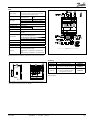
ADAP-KOOL® Refrigeration control systems
Contents
Introduction .......................................................................................4
Compressor- and condenser controls ..............................................6
Introduction ............................................................................................................... 6
Capacity control ........................................................................................................ 8
EKC 331T ......................................................... 8
AK-PC 530 .....................................................12
AK-PC 840 .....................................................18
AK-PC 730 .....................................................20
AKC 25H1 ......................................................22
AKC 25H3 ......................................................23
AKC 25H5 ......................................................24
Water chiller control ..............................................................................................25
AKC 25H7 ......................................................25
AK-CH 650 ....................................................26
Dry cooler ..................................................................................................................28
AK-PC 420 .....................................................28
Liquid injection in the suction line ..................................................................30
EKC 319A.......................................................30
Speed control of compressor and condenser................................32
Introduction .............................................................................................................32
AKD 2800 ......................................................33
AKD 5000 .....................................................34
Accessories for AKD ..................................35
RGE..................................................................36
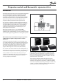
Evaporator controls and thermostatic expansion valves.............38
Introduction .............................................................................................................38
Temperature control .............................................................................................40
EKC 100..........................................................40
EKC 102..........................................................42
Refrigeration appliance controls ......................................................................50
EKC 301..........................................................50
EKC 202..........................................................56
EKC 202D ......................................................62
AK-CC 210.....................................................70
AK-CC 250.....................................................79
AK-CC 450.....................................................80
Media temperature control ................................................................................82
EKC 361..........................................................82
EKC 368..........................................................86
Evaporator controls and electrically operated
expansion valves .............................................................................90
Introduction .............................................................................................................90
Refrigeration appliance controls ......................................................................92
EKC 414A.......................................................92
EKC 414A1 ....................................................96
EKC 414C1 ................................................. 101
EKC 514B1 ................................................. 106
AK-CC 550.................................................. 112
AK-CC 750.................................................. 114
AKC 114-116 ............................................. 116
AKC 121A ................................................... 117
Cold storage room control ............................................................................... 118
AKC 72A ..................................................... 118
AKC 121B ................................................... 119
AKC 151R ................................................... 120
RK0YG302
©
Danfoss
04/2007
1
Water chiller control ........................................................................................... 122
EKC 312....................................................... 122
EKC 315A.................................................... 126
EKC 316A.................................................... 130
Liquid level control ............................................................................................. 134
EKC 347....................................................... 134
Wireless temperature monitoring................................................138
AK-Wireless ............................................... 138
Accessories .....................................................................................140
IO modules for the AK series ........................................................................... 140
Module overview .................................... 141
AK-XM 101A .............................................. 142
AK-XM 102A/B ......................................... 142
AK-XM 204A/B ......................................... 143
AK-XM 205A/B ......................................... 144
AK-OB 101A .............................................. 145
AK-XM 107A .............................................. 145
AK-PS 075/150/250 ............................... 146
AK-OB 003A .............................................. 147
AK-XM 208B .............................................. 147
Display ..................................................................................................................... 148
EKA 161/162/163/164 .......................... 148
Display console ....................................... 150
EKA 165 ...................................................... 151
AKA 14 ........................................................ 152
AKA 15 ........................................................ 152
Thermometer ........................................................................................................ 153
EKA 151 ...................................................... 153
Temperature sensors......................................................................................... 154
AKS 11, AKS 12, AKS 21 ......................... 154
EKS 111 ....................................................... 156
EKS 211 ....................................................... 157
Pressure transmitters ......................................................................................... 158
AKS 32, AKS 33 and AKS 32R .............. 158
Level transmitter.................................................................................................. 161
AKS 41 ......................................................... 161
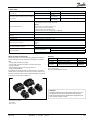
Expansion valves ................................................................................................. 162
AKV 10, AKV 15, AKV 20........................ 162
AKVA 10 AKVA 15, AKVA 20................. 165
Coils for expansion valves .................. 168
ETS ............................................................... 170
ICM ............................................................... 172
Evaporation pressure valve.............................................................................. 174
KVS ............................................................... 174
Gas detector .......................................................................................................... 176
GD ................................................................ 176
2
RK0YG302
©
Danfoss
05/2007
System units ...................................................................................178
System unit 1 ........................................................................................................ 178
AK-SM 720 ................................................. 179
AK-PI 200.................................................... 179
Web-based operation ........................... 180
AK-ST 500 .................................................. 180
EM 100 ........................................................ 181
Optimisation ............................................ 182
System unit 2 ........................................................................................................ 184
AK-SM 350 ................................................. 184
System unit 3 ........................................................................................................ 186
AK-SC 255 .................................................. 186
System unit 4 ........................................................................................................ 188
AKA 245...................................................... 188
AKA 243A................................................... 188
AKA 241...................................................... 188
Operation .................................................. 189
AKA 21 ........................................................ 189
AK-Monitor................................................ 189
MIMIC .......................................................... 189
AKM 4 ......................................................... 189
AKM 5 .......................................................... 189
Optimisation ............................................ 190
Accessories ............................................................................................................ 192
AKA 231...................................................... 192
AKA 222/223............................................. 193
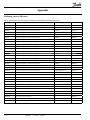
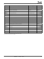
Appendix ........................................................................................194
Ordering survey AK series ................................................................................ 194
RK0YG302
©
Danfoss
04/2007
3
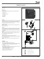
Introduction
Danfoss has s a comprehensive offer to the food retail industry
that consists of electronic controls, compressors, condensing
units, line components and services which provide optimisation
control of refrigeration system and energy savings with HACCP
compliance at the same time.
Electronic controls, as vital part of ADAP-KOOL® Refrigeration
Control System, offer a complete electronic system for control,
monitoring, and alarm handling for supermarket refrigeration
covering Compressor and condensers capacity control, Evaporator
and cold room control, HVAC and lighting control and CO2
applications in refrigeration.
ADAP-KOOL® Refrigeration Control System and its features
make possible optimisation of refrigeration performance and
energy savings with variety of features and function according to
application requirements. That is possible due intelligent features
such as adaptive superheat control, floating condensing pressure
and suction pressure optimisation enabled by using electronic
expansion valve AKV, speed control of compressors and/or
condensers using AKD variable speed drives, intelligent defrost,
automatic fault detection and diagnosis, etc.
4
RK0YG302
©
Danfoss
Advanced ADAP-KOOL® solutions are Hazard Analysis Critical
Control Point (HACCP) compliant and provide HACCP registration.
ADAP-KOOL® refrigeration control system makes the job of
complying with HACCP much easier where controllers maintain
critical temperature points, to selected limits, at measured time
intervals which can be accurately monitored, and logged against
defined parameters providing appropriate documented evidence
of HACCP compliance through simple and automatic recording
of the critical points. Data logs can be set-up to identify critical
temperatures for each area, cabinet or cold room as required and
can be easily adapted to identify and note any incidents such as
case cleaning etc. for your HACCP registration either gathered via
communication system or direct from controllers. ADAP-KOOL®
controller series combined with AKS Pt 1000 temperature sensors
maintain close and accurate set-point temperature control less
then +/- 1°C as it is required in EN441-13 without additional
calibration.
05/2007
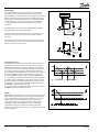
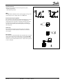
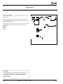
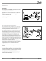
Three Level of Control
ADAP-KOOL®
ion
trol & Optimisat
Supervisory Con
ntrol
Co
rvisory
Supe
m
Alar
rol &
ont
al C
Loc
For reliable control
and operation
For improved
monitoring and
contol of
refrigeration
performance with
remote communication
and alarm
Supervisory control
and optimisation with
advanced automatic.
Fault Detection and
Diagnosis drives energy
usage down and
enhances operational
performance, resulting
in lower lifetime cost
ADAP-KOOL® Refrigeration Control System is compact, flexible,
easy to install and program and enables the solution to grow
with the application needs. This flexible modular concept allows
the constantly adaptation to the application development easy
retrofitting an existing installation. ADAP-KOOL® controls offer
three levels of control for different application demands with
growing benefits and energy savings features according to your
needs:
• Local control and alarm solutions ensure accurate control and
reliable operation of refrigeration system with possibility of
HACCP compliance.
• Supervisory control as more advanced solution comprises
remote alarm with data communication, some energy savings
features with HACCP registration.
• Supervisory Control and Optimisation provides optimised
control with furthermore energy saving features like master
control, intelligent defrost, fault detection and diagnosis with
extended remote service capabilities and HACCP registration
and compliance.
Electronic controls described in this catalogue consist of the following controls:
Compressor and condensers capacity controls are used from
relatively small basic systems with just two hermetic compressors,
to large power packs with multiple semi-hermetic compressors
equipped with variable speed drives and unloaders. ADAPKOOL® Pack controls offer different levels of solutions: From
compressor capacity control and step/variable control with local
alarm ensuring accurate control and operational confidence, to
advanced solutions of control up to 12 compressors or fans with
intelligent control that optimised both suction and condensing
pressure according to the load and external temperatures.
Evaporator and cold room controls cover regulation from simple
thermostat controls with room temperature control via pump
down or compressor start/stop regulation up to electronic expansion valves regulation with many intelligent functions and energy
savings. In addition, different levels of evaporator solutions are
offered: From local temperature control of one evaporator with
alarm ensuring easy and reliable control and operational confidence, to advanced control up to 4 evaporators where controllers
are capable to regulate simultaneously temperature, defrosting,
door frame, rail heat, light and fan operation. Advanced features
like defrost function, adaptive superheat control with AKV electronic expansion valve, intelligent fault detection with diagnosis and pulsing of rail heat and fans making possible optimal
functionality of refrigeration system saving energy and keep food
quality in display cases and cold rooms.
Variable speed control of compressors and condenser fan with
variable speed drive AKD reduces energy consumption and refrigerant charge as well noise level. Use of AKD stabilise condensing
pressure and reduce dirt build-up on condenser.
All ADAP-KOOL® controls are designed to be used as stand alone
or to be integrated into a complete ADAP-KOOL® refrigeration
control system solution using data communication. That enables
local or remote monitoring with alarm handling, control of your
refrigeration system and proactive service management while
reducing running costs.
RK0YG302
©
Danfoss
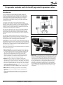
ADAP-KOOL® controls in CO2 refrigeration applications
Due environmental and cost reasons, CO2 is becoming more and
more utilised refrigerant in Food Retail refrigeration applications.
Installation costs as well as energy costs are on the same level as
in traditional refrigeration systems without any extra costs while
the performance of refrigeration systems remains consistent.
ADAP-KOOL® refrigeration control system is designed to handle
the challenges with CO2. All the benefits of the advanced adaptive control system as e.g. energy saving master control functions
can also be utilised in a CO2 based refrigeration plant. At present
Danfoss control solutions are available for all cascade systems and
during the last years several large installations has been installed
running with CO2 controlled by ADAP-KOOL® for both medium
and low temperature applications. Danfoss is preparing a control
solution for trans critical CO2 system and also the necessary line
components.
Enterprise Level Services - RETAIL-CARETM
For chain-store customer with many and diverse outlets further
services like Alarm/Service management, Energy management,
performance reports including HACCP documentation and key
asset performance indicators are essential to optimise operating
cost. For these services, Danfoss has developed a suite of expert
services under the banner of RETAIL-CARETM, delivering a complete set of management tools to assist retailers in the ongoing
management and reduction of operational costs. Within Food
Retail business, these services also help to provide, maintain and
document food quality. ADAP-KOOL® refrigeration controls are an
integral part of RETAIL-CARETM services.
Danfoss’ extensive product range lets you configure a complete
solution for your business from a vast array of products for different applications, including not only the ADAP-KOOL® range, but
also compressors, sight glasses, solenoid valves, check valves, ball
valves, shut-off valves, filter driers (cores and casings), pressure
controls and expansion valves. Details about these components
are available in other Danfoss literature.
04/2007
5
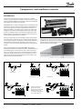
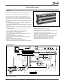
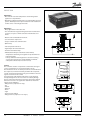
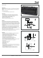
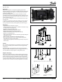
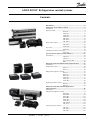
Compressor- and condenser controls
Introduction
Compressor and condensers capacity controls are used from
compact systems with just two hermetic compressors up to large
power-packs with multiple semi-hermetic compressors equipped
with variable speed drives and unloaders.
ADAP-KOOL® Pack controls offer different levels of solutions: from
compressor capacity control and step/variable control with local
alarm ensuring accurate control and operational confidence, to
advanced solutions of control up to 12 compressors or fans with
intelligent control that optimised both suction and condensing
pressure according to the load and external temperatures. Intelligent features such as floating condensing pressure control and
suction pressure optimisation are enabled.
Further energy savings are achieved with variable speed control
of condenser fans and compressors and other advanced features
such as adaptive defrost, self-diagnosis and automatic fault detection of blocked condenser. These features reduce service and
maintance costs and achieving optimal efficiency of refrigeration
system.
Among many benefits of having ADAP-KOOL® Refrigeration
Control System with full communication offer a well informed and
structured diagnostic tool for remote service. Almost all parameters are accessible via this remote communication. For example,
signals like “night setback” are sent to all controllers in the network, which avoid extra installation wiring and site labour costs,
while ensuring system optimisation.
Danfoss provides solutions in three different levels to cover different applications. These ensure you that in choosing Danfoss Pack
Controllers your refrigeration control system perfectly matched
to your application, without being over dimensioned or unnecessarily complex.
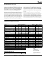
Supervisory
Control
Local Control & Alarm
EKC 331T Capacity control
AK-PC 530 Reliable control
Suction unit
Power pack
Condenser
Variable speed drive of
Compressors and/or
Condenser Fans with AKD
will reduce the energy
consumption and improve
your system efficiency
6
RK0YG302
©
Danfoss
Supervisory
Control &
Optimisation
05/2007
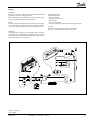
AK-PC 840 Intelligent control
Brief outline about some of the controls
Controller series AKC 25H_ is a complete control unit for capacity
regulation of compressors and condensers in small refrigerating
systems ensuring precise and stable refrigeration plant suction
and condensing pressure regulation. Being a part of ADAP-KOOL®
Refrigeration control systems, the compressor control ensures
optimum monitoring and alarm procedures and the possibility
of different monitoring functions to optimise refrigeration plant
operation.
EKC 331T controller is used for capacity regulation of compressors or condensers in compact refrigerating systems monitoring
minimum and maximum pressure. Regulation can be carried out
with up to 4 identical capacity steps. Step control with EKC 331T
reduces number of cut in/cut out cycles using patented smart
neutral zone control of the compressor. Using optional LON module, EKC 331T can be integrated into ADAP-KOOL® system.
AK-PC 530 controller is used for capacity regulation of compressors or condensers in refrigerating systems where compressor and
condenser control is based on a pressure transmitter or temperature sensor. There are eight outputs for control up to 8 compressors and/or 8 fans. More fan outputs can be added via the connection of one or two EKC 331T as slave modules (up to 8 fan steps).
This analogue output can also be used for an external AKD speed
drive to control all condensers. Setup of controller is very userfriendly by selection of a pre-defined compressor configuration.
AK-PC 840 controller is used for capacity control of complete
power pack in medium to big refrigeration systems. The modular
design with AK extension modules allows up to 12 compressors
with 3 unloaders, and up to 12 condenser fans. The controller offers universal thermostats, pressostats, alarm inputs and analogue
inputs, based on already available measurements or extra inputs.
This functionality minimises the use of extra external equipment.
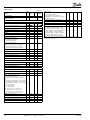
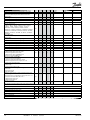
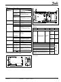
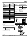
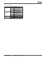
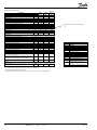
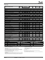
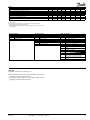
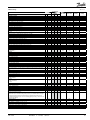
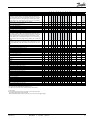
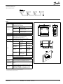
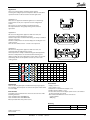
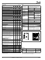
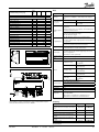
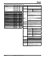
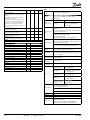
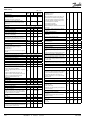
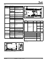
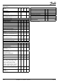
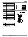
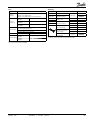
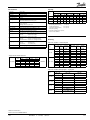
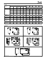
Comparison of controls in this section
Capacity control
Function
Type EKC 331T
5
Number of outlets
Expansion of number of
outlets
Total number of inputs and
outlets
Max. number of compressors
Compressor control
Control
Control sensor, compressor
8
Compressor and Condenser
AK-PC 530 AKC 25H1 AKC 25H3 AKC 25H5
10
11
11
11
2x EKC 331T
33 + 8
4
8
Step
Step
NZ
NZ
Pressure/
Pressure/
Temperature Temperature
Safety signal per compressor
1
Night setback
X
X
P0 - optimisation
X
Load shedding
Three-way valve control
Pump control
Max. number of fans
4
8
Fan control
Step
Step/Speed
PI/P control
NZ
P/PI
Control sensor,
Pressure/
Pressure/
condenser
Temperature Temperature
Floating condenser pressure
X
Heat recovery function
X
Condenser error monitoring
Display
Yes
Option
Data communication
Option
Option
General alarm input
5
General thermostat
General pressure switch
General analogue input
27
34
9
Step
NZ
Pressure
9
Step
NZ
Pressure
32
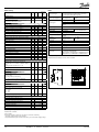
AK-PC 840
Basis 8
Up to 40
Up to 80
Cascade
Chiller
Dry cooler
AK-PC 730 AK-CH 650 AK-PC 420
Basis 8
Basis 8
10
Up to 40
Up to 40
Up to 40
30
9
12
4
Step/Speed Step/Speed Step/Speed Step/Speed
PI
PI
PI
PI
Pressure
Pressure/
Temperature
Temperature
Up to 6
Up to 6
Up to 6
Up to 6
Up to 6
Up to 6
via AKC 22H via AKC 22H via AKC 22H
X
X
X
X
X
X
X
X
X
X
X
X
X
XX
XX
X
X
X
12
6
6
Step/Speed Step/Speed Step/Speed Step/Speed
P/PI
P/PI
PI
P/PI
Pressure/
Pressure/
Pressure/
Pressure/
Temperature Temperature Temperature Temperature
X
X
X
X
X
X
X
X
X
X
X
Option
Option
Option
Option
LON RS 485 LON RS 485 LON RS 485
Option
Max. 10
Max. 10
Max. 10
3
Max. 5
Max. 5
Max. 5
Max. 5
Max. 5
Max. 5
Max. 5
Max. 5
Max. 5
X
9
9
9
NZ
Pressure
PI
Pressure
PI
Pressure
X
X
X
X
DANBUSS
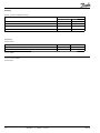
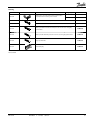
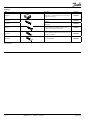
Expanded water cooling control
Function
Capacity control of brine system
AKC 25H7
X
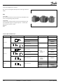
Note
Adjustable speed is not available
on all compressors.
Check compressor data.
Fluid injection in the suction pipe
Function
Limiting the discharge gas temperature
EKC 319
X
RK0YG302
©
Danfoss
04/2007
A list of AKC controls can be
found at the back of the catalogue.
7
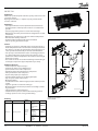
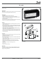
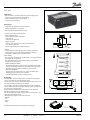
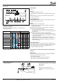
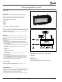
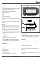
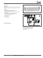
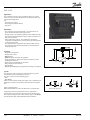
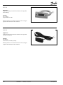
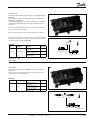
Capacity control
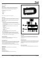
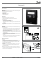
EKC 331T
Application
The controller is used for capacity regulation of compressors or
condensers in small refrigerating systems.
Regulation can be carried out with up to four identical capacity
steps.
Advantages
• Patented neutral zone regulation
• Sequential or cyclic operation
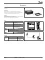
Functions
• Regulation
Regulation with up to four relay outputs can be carried out.
Regulation takes place with a set reference which is compared to
a signal from a pressure transmitter or a temperature sensor.
• Relay module
It is possible to use the controller as relay module, so that the
relays are cut in or out by means of an external voltage signal.
• Alarmfunction
A relay becomes activated when the set alarm limits are exceeded.
• Digital input
The digital input can be used for:
- night operation where the suction pressure is raised
- heat recovery where the condensing pressure is raised
- external start/stop of the regulation.
- Monitoring of safety circuit
• Possibility of data communication
Display
A signal from a pressure transmitter will always be converted and
shown as a temperature value.
Settings are made as for temperature values.
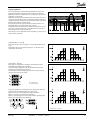
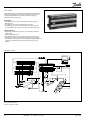
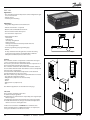
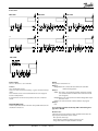
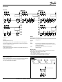
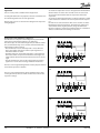
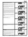
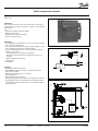
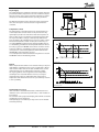
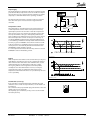
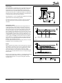
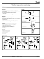
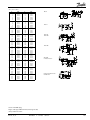
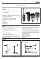
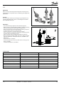
Capacity regulation
The cut-in capacity is controlled by signals from the connected
pressure transmitter (temperature sensor) and the set reference.
Outside the reference a neutral zone is set where the capacity will
neither be cut in nor out.
Outside the neutral zone (in the hatched areas named +zone and
-zone) the capacity will be cut in or out if the regulation registers
a change of pressure (the temperature) “away” from the neutral
zone. Cutin and cutout will take place with the set time delays.
If the pressure (the temperature) however “approaches” the
neutral zone, the controller will make no changes of the cut-in
capacity.
If regulation takes place outside the hatched area (named ++zone
and --zone), changes of the cut-in capacity will occur somewhat
faster than if it were in the hatched area.
Cutin of steps can be defined for either sequential or cyclic operation.
8
RK0YG302
©
Danfoss
05/2007
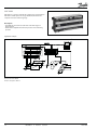
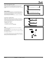
EKC 331T
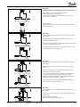
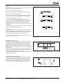
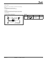
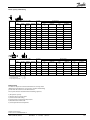
Sequential
The relays are here cut in in sequence – first relay number 1, then
2, etc.
Cutout takes place in the opposite sequence, i.e. the last cut-in
relay will be cut out first.
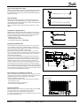
Cyclic
The relays are coupled here so that the operating time of the
individual relays will become equalised.
At each cutin the regulation scans the individual relays’ hours,
cutting in the relay with least time on it.
At each cutout a similar thing happens. Here the relay is cut out
that has most hours on the hours.
Rx = random relay
h = number of hours
If capacity regulation is carried out on two compressors with one
unloader each, the following function can be used:
Relays 1 and 3 are connected to the compressor motor.
Relays 2 and 4 are connected to the unloaders.
Relays 1 and 3 will operate in such a way that the operating time
for the two relays will become equalised.
C = compressor, L = Unloader
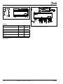
Relay module
The controller can also be used as a relay module where the relays
in the module are operated by the received voltage signal. The
signal must be connected to terminal 15-16.
Depending on the definition of the signal and the number of
relays used, the relays will be ”distributed” over the signal.
A hysteresis at the individual coupling points will ensure that the
relay will not cut in or out when not required.
EKC 331T
RK0YG302
©
Danfoss
04/2007
9
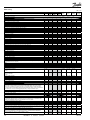
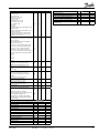
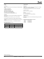
Menu survey
SW: 1.1x
Parame- Min.
ter
Function
Factory
setting
Max.
Normal display
Shows the signal from the temperature sensor/
pressure transmitter
-
°C
Reference
Set the regulation’s set point
-
-60 °C
170 °C 3
Neutral zone
r01
0.1 K
20 K
Max. limitation of set point setting
r02
-60 °C
170 °C 50
4.0
Min. limitation of set point setting
r03
-60 °C
50 °C
-60
Correction of signat from the sensor
r04
-20 K
20 K
0.0
Select unit (C-b=°C and F-P= °F)
r05
C-b
F-P
C-b
Reference displacement by signal at DI input
r13
-50 K
50 K
0
c01
0 min.
30 min 2
Min. time period between cutins of same relay
c07
0 min.
60 min. 4
Definition of regulation mode
1: Sequential (step mode/FILO)
2: Cyclic (step mode/FIFO)
3: Compressor with unloader
c08
1
3
1
If the regulation mode 3 has been selected, the
relays for the unloaders can be defined to:
no: Cut in when more capacity is required
nc: Cut out when more capacity is required
c09
no
nc
no
Regulation parameter for + Zone
c10
0.1 K
20 K
3
Regulation parameter for + Zone min.
c11
0.1 min. 60 min. 2
Regulation parameter for ++ Zone seconds
c12
1s
180 s
30
Regulation parameter for - Zone
c13
0K
20 K
3
Regulation parameter for - Zone min.
c14
0.1 min. 60 min. 1
Regulation parameter for - - Zone seconds
c15
1s
180 s
90 min. 30
o22
0
3
0
o23
0h
999 h
0
Operating hours of relay 2 (value times 10)
o24
0h
999 h
0
Operating hours of relay 3 (value times 10)
o25
0h
999 h
0
Operating hours of relay 4 (value times 10)
o26 0 h
999 h 0
Setting of refrigerant
1=R12. 2=R22. 3=R134a. 4=R502. 5=R717.
6=R13. 7=R13b1. 8=R23. 9=R500. 10=R503.
11=R114. 12=R142b. 13=User defined. 14=R32.
o30 0
30
0
15=R227. 16=R401A. 17=R507. 18=R402A.
19=R404A. 20=R407C. 21=R407A. 22=R407B.
23=R410A. 24=R170. 25=R290. 26=R600.
27=R600a. 28=R744. 29=R1270. 30=R417A
*) This setting will only be possible if a data communication moduel has been
installed in the controller.
Capacity
Min. ON time for relays
Define DI input:
0: not used
1: Contact displaces reference
2: Contact starts and stops regulation
3: Interrupted contact will cut out the capacity,
and alarm will be given.
Operating hours of relay 1 (value times 10)
30
Alarm
Alarm time delay
A03
1 min.
Upper alarm limit (absolute value)
A10
-60 °C
170 °C 50
Lower alarm limit (absolute value)
A11
-60 °C
50 °C
Controllers address
o03*
1
60
0
On/off switch (service-pin message)
o04*
-
-
-
-60
Miscellaneous
o05
Define input signal and application:
0: no signal /regulation stopped
1: 4-20 mA pressure transmitter - compressor
reg.
2: 4-20 mA pressure transmitter - condenser reg.
3: AKS 32R pressure transmitter - compressor reg.
4: AKS 32R pressure transmitter - condenser reg.
o10
5: 0 - 10 V relay module
6: 0 - 5 V relay module
7: 5 - 10 V relay module
8: Pt 1000 ohm sensor - compressor reg.
9: Pt 1000 ohm sensor - condenser reg.
10: PTC 1000 ohm sensor - compressor reg.
11: PTC 1000 ohm sensor - condenser reg.
Set supply voltage frequency
o12
off(-1)
100
-
0
11
0
50 Hz
60 Hz
50
Manual operation with “x” relays
o18
0
4
0
Define number of relay outputs
o19
Access code
1
4
4
Pressure transmitter’s working range - min. value o20
-1 bar
0 bar
-1
Pressure transmitter’s working range - max. value o21
1 bar
40 bar 12
10
RK0YG302
©
Danfoss
05/2007
EKC 331T
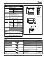
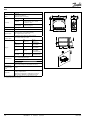
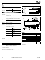
Data
Supply voltage
230 V a.c. +/-15% 50/60 Hz, 5 VA
Pressure transmitter*) with 4-20 mA or
temperature sensor Pt 1000 ohm or
temperature sensor PTC 1000 ohm or
voltage signal (0 - 5 V, 0 - 10 V or 5 - 10 V)
Input signal
Digital input to external contact function
AC-1: 4 A (ohmic)
AC-15: 3 A (inductive)
AC-1: 4 A (ohmic)
AC-15: 1 A (inductive)
Relay output
4 pcs. SPST
Alarmrelay
1 pcs. SPST
Data communication
Possible to connect a data communication
module
-10 - 55°C, during operation
-40 - 70°C, during transport
Environments
20 - 80% Rh, not condensed
No shock influence/vibrations
Enclosure
IP 20
Weight
300 g
Mounting
DIN rail
Display
LED, 3 digits
Terminals
max. 2.5 mm2 multicore
Approvals
EU Low voltage Directive and EMC demands re
CE-marking complied with.
LVD-tested acc. to EN 60730-1 and EN 60730-2-9
EMC-tested acc. to EN50081-1 and EN 50082-2
Black
Brown
Blue
*) As pressure transmitter can be used AKS 32R or AKS 33.
The installation of data communications must comply with the requirements described in literature sheet no. RC8AC
Data communication
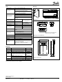
Ordering
Type
Function
Ordering
EKC 331T
Capacity controller
084B7105
EKA 175
Data communication module
(accessories), (RS 485 module)
084B7093
Additional information!
Manual: RS8CU
EKC 331T
RK0YG302
©
Danfoss
04/2007
11
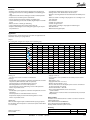
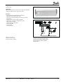
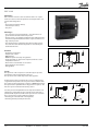
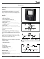
AK-PC 530
Application
The controller is used for capacity regulation of compressors or
condensers in small refrigerating systems.
Numbers of compressors and condensers can be connected, as
required.
There are eight outputs and more can be added via an external
relay module.
Advantages
• Patented neutral zone regulation
• Many possible combinations for compressor constellations
• Sequential or cyclic operation
• Possibility of suction pressure optimisation via the data communication
Regulation
Regulation is based on signals from one pressure transmitter for
the compressor regulation and one pressure transmitter for the
condenser regulation plus one temperature sensor for the air
temperature before the condenser.
The two pressure transmitters can be replaced by two
temperature sensors when regulation has to be carried out on
brine systems.
• Pressure regulation P0 (pack)
• Temperature regulation Sx (chiller)
• Pressure regulation Pc (pack/chiller)
• Pressure regulation with variable reference (Sc3)
Functions
• Relays for compressor and condenser regulation
• Voltage output for capacity regulation of condenser
• Status inputs. An interrupted signal indicates that the safety
circuit has been activated and the respective circuit stopped
• Contact inputs for indication of alarms
• Contact inputs for displacement of references or for indication of
alarms
• Alarm relay
• External start/stop of regulation
• Possibility of data communication
Operation
All operation takes place either via data communication or via
connection of a display type EKA 164 or EKA 165.
Combinations
The controller has ten relay outputs two of which have been
reserved for the alarm function and for the ”AKD start/stop”
function.
For a start relays are reserved for compressor capacities starting
from DO1, DO2, etc.
The remaining relays up to and including DO8 will then be
available for fans. If more are required, one or more relay modules
type EKC 331 with max. eight steps can be connected. The signals
to these modules are to be taken from the controller’s analog
output. Another solution could be that the fan speed is controlled
via the analog output and a frequency converter.
If the alarm function and the ”AKD start/stop” function are left out,
all ten relay outputs may be used for compressors and fans (but
max. eight for compressors and max. eight fans).
12
RK0YG302
©
Danfoss
05/2007
Compressors and unloaders can
be combined in various ways.
AK-PC 530
Capacity regulation
The cut-in capacity is controlled by signals from the connected
pressure transmitter/temperature sensor and the set reference.
Outside the reference a neutral zone is set where the capacity will
neither be cut in nor out.
Outside the neutral zone (in the hatched areas named +zone and
-zone) the capacity will be cut in or out if the regulation registers a
change of pressure “away” from the neutral zone. Cutin and cutout
will take place with the set time delays.
If the pressure however “approaches” the neutral zone, the controller will make no changes of the cut-in capacity.
If regulation takes place outside the hatched area (named ++zone
and --zone), changes of the cut-in capacity will occur somewhat
faster than if it were in the hatched area.
Cutin of steps can be defined for either sequential, cyclic, binary or
"mix & match" operation.
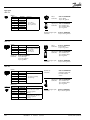
Sequential (first in - last out)
The relays are here cut in in sequence – first relay number 1, then
2, etc.
Cutout takes place in the opposite sequence, i.e. the last cut-in
relay will be cut out first.
Cyclic (first in - first out)
The relays are coupled here so that the operating time of the
individual relays will become equalised.
At each cutin the regulation scans the individual relays’ hours,
cutting in the relay with least time on it.
At each cutout a similar thing happens. Here the relay is cut out
that has most hours on the hours.
Rx = random relay
h = number of hours
If capacity regulation is carried out on two compressors with one
unloader each, the following function can be used:
Relays 1 and 3 are connected to the compressor motor.
Relays 2 and 4 are connected to the unloaders.
Relays 1 and 3 will operate in such a way that the operating time
for the two relays will become equalised.
C = compressor, L = Unloader
AK-PC 530
RK0YG302
©
Danfoss
04/2007
13
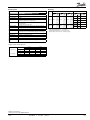
Menu survey
Sequence
1. o61 must be set as the first parameter. This parameter determines which of the four operating interfaces (application mode) are
activated. This must be set via the display keys. It cannot be set via data communication. (Active functions are shown below in shaded
fields.)
2. Quick- start
To get the system up and running quickly so that cooling can be commenced, start it by setting the following parameters (these parameters can only be set when the regulation is stopped, r12=0):
r23, r28 and then either (c08, c09 and c16) or (c17 to 28) – continue with c29, o06, o30, o75, o76, o81 and finally r12=1.
3. Once the regulation is under way, you can go through the other parameters and adjust them in situ.
o61 =
Parameter
Function
Normal display
Shows P0 in EKA 165 (display with buttons)
Shows Pc in EKA 163
-
1
°C
°C
2
P
P
Min.
3
°C
°C
Max.
Factory
setting
4
P
P
°C/bar
°C/bar
P0 reference
Neutral zone
Correction of signal from P0 sensor
Select unit (0=bar and °C, 1=Psig and °F)
Start/Stop of regulation
r01
r04
r05
r12
0.1°C/0.1 bar
-50°C /-5.0 bar
0
OFF
20°C /5.0 bar
50°C/5.0 bar
1
ON
4.0°C/0.4 bar
0.0
0
OFF
Reference offset for P0 (see also r27)
r13
-50°C/-5.0 bar
50°C/5.0 bar
0.0
Set regulation setpoint for P0
Shows total P0 reference
( r23 + various displacements)
Limitation: P0 reference max. value
(also applies to regulation with reference displacement)
Limitation: P0 referencen min. value
(also applies to regulation with reference displacement)
Displacement of P0 (ON=active “r13”)
Pc reference
Set regulation setpoint for Pc
r23
-99°C/-1 bar
30°C/60.0 bar
0.0°C/3.5 bar
r24
°C/bar
r25
-99°C/-1.0 bar
30°C/60.0 bar
30.0°C/40.0 bar
r26
-99°C/-1.0 bar
30°C/40.0 bar
-99.9°C/-1.0 bar
r27
OFF
ON
OFF
r28
-25°C/0.0 bar
75°C/60.0 bar
35°C/15.0 bar
Shows total Pc reference
r29
°C/bar
Limitation: Pc referencen max. value
r30
-99.9°C/-0.0 bar
99.9°C/60.0 bar
Limitation: Pc referencen min. value
r31
-99.9°C/0.0 bar
99.9°C/60.0 bar
-99.9°C/0.0 bar
Correction of signal from Pc sensor
r32
Pc reference variation.1 and 2 are PI-regulation
1: Fixed reference. “r28” is used
2: Variable reference. Outdoor temperature (Sc3) included
r33
in the reference
3: As 1, but with P-regulation (Xp-band)
4: As 2, but with P-regulation (Xp-band)
-50°C/-5.0 bar
50°C/5.0 bar
0.0
1
4
1
Reference offset for Pc
The mean temperature difference across the condenser at
maximum load (dim tm K)
The mean temperature difference across the condenser at
the lowest relevant compressor capacity (min tm K)
This is where you can see the actual pressure (P0) that is
being measured by the pressure transmitter.
This is where you can see the actual pressure (T0) that is
part of the regulation. From the sensor which is defined
in “o81”
Capacity
r34
-50°C/-5.0 bar
50°C/5.0 bar
0.0
r35
3.0
50.0
10.0
r56
3.0
50.0
8.0
Min. ON time for relays
Min. time period between cutins of same relay
Definition of regulation mode
1: Sequential (step mode/FILO)
2: Cyclic (step mode/FIFO)
3: Binary and cyclic
If a regulation mode with unloaders is selected, the relay
must be defined to:
0: Cut in when more capacity is required
1: Cut out when more capacity is required
c01
c07
0 min
0 min.
30 min.
60 min
0
4
c08
1
3
1
c09
0
1
0
Regulation parameter for + Zone
c10
0.1 K/0.1 bar
20 K/2.0 bar
4.0/0.4 bar
Regulation parameter for + Zone
c11
0.1 min
60 min
4.0
r57
°C/bar
r58
°C
55.0°C/60.0 bar
Regulation parameter for ++ Zone
c12
0.1 min.
20 min
2.0
Regulation parameter for - Zone
c13
0.1 K/0.1 bar
20 K/2.0 bar
4.0/0.3 bar
To be continued
14
RK0YG302
©
Danfoss
05/2007
AK-PC 530
Regulation parameter for - Zone
c14
0.1 min.
60 min
1.0
Regulation parameter for - - Zone
c15
0.02 min.
20 min
0.5
Definition of compressor connections.
Following "c17" to "c28" is another way to define compressorw than with "c16".. A code will then have to be set for
the relays that are to be ON at the different steps:
Step 1 (M&M operation)
Step 2 (M&M operation)
Step 3 (M&M operation)
Step 4 (M&M operation)
Step 5 (M&M operation)
Step 6 (M&M operation)
Step 7 (M&M operation)
Step 8 (M&M operation)
Step 9 (M&M operation)
Step 10 (M&M operation)
Step 11 (M&M operation)
Step 12 (M&M operation)
Definition of condenser:
1-8: Total number of fan relays or voltage step on the
voltage output
9: Only via analog output and start of frequency converter
10: Not used
11- 18: Total number of fan relays which are to be connected with alternating start-up.
Cut in compressor capacity with manual control. See also
“c32”
Manual control of compressor capacity (when ON, the
value in “c31” will be used)
Pump down limit. Limit value where the last compressor
is cut out.
Proportinal band Xp for (P= 100/Xp) condenser regulation
I: Integration time Tn for condenser regulation
Cutin condenser capacity with manual control. See also
“n53”
Manual control of condenser capacity (when ON, the
value in “n52” will be used)
Start speed The voltage for the speed regulation is kept
at 0 V until the regulation requires a higher value than the
value set here.
Min. speed. The voltage for the speed regulation switches
to 0 V when the regulation requires a lower value than the
value set here.
Alarm
Delay time for a A32 alarm
Low alarm and safety limit for P0
Delay time for a DI1 alarm
Delay time for a DI2 alarm
Delay time for a DI3 alarm
Upper alarm and safety limit for Pc
Upper alarm limit for sensor "Saux1"
Delay time for a P0 alarm
Delay time for a Pc alarm
Miscellaneous
Controllers address
On/off switch (service-pin message)
c16
1
26
0
c17
0
15
0
c18
c19
c20
c21
c22
c23
c24
c25
c26
c27
c28
0
0
0
0
0
0
0
0
0
0
0
15
15
15
15
15
15
15
15
15
15
15
0
0
0
0
0
0
0
0
0
0
0
c29
0/OFF
18
0
c31
0%
100%
0
c32
OFF
ON
OFF
c33
-99.9°C/-1.0 bar
100°C/60 bar
100°C/60 bar
n04
n05
0.2 K/0.2 bar
30 s
40.0 K/10.0 bar
600 s
10.0 K/3.0 bar
150
n52
0%
100%
0
n53
OFF
ON
OFF
n54
0%
75%
20%
n55
0%
50%
10%
A03
A11
A27
A28
A29
A30
A32
A44
A45
0 min.
-99°C/-1.0 bar
0 min. (-1=OFF)
0 min. (-1=OFF)
0 min. (-1=OFF)
-10 °C/0.0 bar
1°C (0=OFF)
0 min. (-1=OFF)
0 min. (-1=OFF)
90 min.
30°C/40 bar
999 min.
999 min.
999 min.
99 °C/60.0 bar
150°C
999 min.
999 min.
0 min.
-40°C/0.5 bar
OFF
OFF
OFF
60.0°C/60.0 bar
OFF
0 min.
0 min.
o03*
o04*
1
-
990
-
o05
1 (0=OFF)
100
OFF
o06
0
7 (1)
0
o12
50 Hz
60 H
0
o18
0
18
0
Access code
Used sensor type for Sc3, Sc4 and "Saux1"
0=Pt 1000, 1=PTC1000
2-7=variations with temperature sensor on P0 and Pc. See
earlier in the manual.
Set supply voltage frequency
Manual control of outputs:
0: No override
1-10: 1 will cut in relay 1, 2 relay 2, etc.
11-18: Gives voltage signal on the analog output. (11
gives 1.25 V, and so on in steps of 1.25 V
*) This setting is only possible if data communication module is mounted in the controller
AK-PC 530
RK0YG302
©
Danfoss
04/2007
To be continued
15
P0 pressure transmitter’s working range - min. value
P0 pressure transmitter’s working range - max. value
Use of DI4-input
0=not used. 1=P0 displacement. 2=alarm function.
Alarm="A31"
Operating hours of relay 1 (value time 1000)
Operating hours of relay 2 (value time 1000)
Operating hours of relay 3 (value time 1000
Operating hours of relay 4 (value time 1000)
Setting of refrigerant
1=R12. 2=R22. 3=R134a. 4=R502. 5=R717. 6=R13.
7=R13b1. 8=R23. 9=R500. 10=R503. 11=R114.
12=R142b. 13=User defined. 14=R32. 15=R227.
16=R401A. 17=R507. 18=R402A. 19=R404A. 20=R407C.
21=R407A. 22=R407B. 23=R410A. 24=R170. 25=R290.
26=R600. 27=R600a. 28=R744. 29=R1270. 30=R417A.
31=R422A.
Use of DI5-input
0=not used. 1=Pc displacment. 2=alarm function.
Alarm="A32"
Pc pressure transmitter’s working range - min. value
Pc pressure transmitter’s working range - max. value
Read temperature at sensor "Saux1"
Operating hours of relay 5 (value time 1000)
Operating hours of relay 6 (value time 1000)
Operating hours of relay 7 (value time 1000)
Operating hours of relay 8 (value time 1000)
Selection of application
1. Temperature signal and "c16" mode
2: Pressure signal and "c16" mode
3. Temperature signal and M&M mode
4. Pressure signal and M&M mode
Function for relay output DO9:
0. Start/stop of speed regulation
1. Inject on signal for evaporator control
2. Boost ready (at least one compressor is on)
3. Start /stop of condenser fan
Function for relay output DO10:
0. Alarm relay
1. Start/stop of condenser fan
Definition of alarm message at DI1 signal:
0. Not used
1. Fan failure (A34)
2. DI1 alarm (A28)
Definition of the signal to the P0 regulation when temperature signal.
If frost protection is required, the setting must be 1 or 2.
0. Pressure transmitter AKS 32R on P0
1. Temperature input Saux
2. Temperature input S4
Display connection
Off: EKA 164
On: EKA 165 (extended display with light-emitting diodes)
Service
Status on DI1 input
Status on DI2 input
Read temperature at sensor "Sc3"
Read temperature at sensor "Sc4"
Status on DI3 input
Status on DI4 input
Status on DI5 input
16
RK0YG302
©
o20
o21
-1 bar
1 bar
0 bar
60 bar
-1.0
12.0
o22
0
2
0
o23
o24
o25
o26
0.0 h
0.0 h
0.0 h
0.0 h
99.9 h
99.9 h
99.9 h
99.9 h
0.0
0.0
0.0
0.0
o30
0
31
0
o37
0
2
0
o47
o48
o49
o50
o51
o52
o53
-1 bar
1 bar
0 bar
200 bar
-1.0
34.0
0.0 h
0.0 h
0.0 h
0.0 h
99.9 h
99.9 h
99.9 h
99.9 h
0.0
0.0
0.0
0.0
1
4
1
o75
0
3
0
o76
0
1
0
o78
0
2
0
o81
0
2
0
o82
Off
On
Off
o61
°C
1
2
u10
u37
u44
u45
u87
u88
u89
Danfoss
3
4
°C
°C
05/2007
AK-PC 530
Data
Supply voltage
Input signal
Montage
24 V a.c. +/-15% 50/60 Hz, 5 VA
2 pcs. Pressure transmitters type AKS 32R
(temperature sensor in brine systems)
3 pcs. temperature sensor input for PT 1000
ohm/0°C or PTC 1000 ohm/25°C
1 pcs. for Start/stop of regulation
Digitale input from
contact function.
8 pcs. for monitoring of safety circuits
3 pcs. for alarm function
2 pcs. for alarm function or for displacement of
references
Relay output for
8 pcs. SPST
capacity regulation
"AKD start/stop" relay 1 pcs. SPST
AC-1: 3 A (ohmic)
AC-15: 2 A (inductive)
Alarm relay
1 pcs. SPDT
AC-1: 6 A (ohmic)
AC-15: 3 (inductive)
Voltage output
0-10 V d.c.
EKA 163
Display outputs
Data communication
Environments
Enclosure
Weight
Mounting
Terminals
Approvals
AK-PC 530
Pc display
Operation, P0 display and
EKA 165(164)
LED
Possible to connect a data communication
module
0 - 55°C, during operation
-40 - 70°C, during transport
Only for front mounting (IP 65)
Only connection via plugs
20 - 80% Rh, not condensing
No shock influence/vibrations
IP 20
0.4 kg
DIN rail or on wall
max. 2.5 mm2 multicore
Display type EKA 163/EKA 164
EU Low voltage Directive and EMC demands re
CE-marking complied with.
LVD-tested acc. to EN 60730-1 and EN 60730-2-9
EMC-tested acc. to EN61000-6-2 and 3
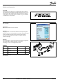
Ordering
Type
Function
Ordering
AK-PC 530
EKA 163B
EKA 164B
Capacity controller
084B8007
Display unit
084B8574
Display unit with operation buttons
084B8575
Display unit with operation buttons
and light-emitting diodes for input and
084B8573
EKA 165
output
084B7298
Cable for display unit 2 m, 1 pcs.
Cable for display unit 6 m, 1 pcs.
084B7299
EKA 175
Data communication module, FTT 10
084B7093
Data communication module, MOD-bus
084B8571
EKA 178B
The installation of data communications must comply with the requirements described in literature sheet no. RC8AC
Display type EKA 165
Additional information!
Manual: RS8EJ
AK-PC 530
RK0YG302
©
Danfoss
04/2007
17
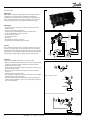
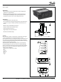
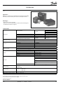
AK-PC 840
Application
AK-PC 840 is a complete regulating unit for capacity control of
compressors and condensers in commercial refrigeration.
In addition to capacity control the controller can give signals to
other controllers about the operating condition, e.g. forced closing of expansion valves, alarm signals and alarm messages.
Advantages
• Control of up to 12 compressors, which can have up to three
unloaders each
• Speed control of two compressors
• Suction pressure optimisation via data communication
• It can handle different compressor sizes
• Control of up to 12 fans
• Speed control of fans
• PI control
• Error detection of dirty condenser
• Separate functions independent of control
Control
The controller’s main function is to control compressors and condensers so that operation all the time takes place at the energyoptimum pressure conditions. Both suction pressure and condensing pressure are controlled by signals from pressure transmitters
transmitting a voltage signal, e.g. types AKS 32 and AKS 32R.
Functions
• Monitoring of safety automation can be connected.
• When the compressors stop when there is an error in the system,
a signal can be given to other controls so that the electronic
expansion valves are closed.
• Alarm signals can be generated directly from the controller and
via data communication.
• Alarms are shown with texts so that the cause of the alarm is
easy to see.
• Liquid injection into suction line
• The status of the outputs and inputs is shown by means of lightemitting diodes on the front panel
• Plus some completely separate functions thar are totally independent of the regulation – such as alarm, thermostat and pressure control functions.
Single compressor control
Single condenser control
Both compressor and condenser control
18
RK0YG302
©
Danfoss
05/2007
AK-PC 840
Data
Supply voltage
24 V a.c. +/- 20%
Power consumption
AK-PC 840
12 VA
Analoge indgange
Pt 1000 ohm /0°C
Dissolution: 0.1°C
Accuracy: +/- 0.5°
Pressure transmitter Dissolution 1 mV
type AKS 32R /
Accuracy +/- 10 mV
AKS 32 (1-5 V)
Max. connection of 5 pressure
transmitters on one module
Voltage signal
0-10 V
On/off supply voltage
inputs
Relay outputs
SPDT
Solid state outputs
Ambient temperature
Enclosure
Contact function
(On/Off )
On at R < 20 ohm
Off at R > 2K ohm
(Gold -plated contacts not necessary)
Low voltage
0/80 V a.c./d.c.
Off: U < 2 V
On: U > 10 V
High voltage
0/260 V a.c.
Off: U < 24 V
On: U > 80 V
AC-1 (ohmic)
4A
AC-15 (inductive)
3A
U
Min. 24 V
Max. 230 V
Low and high voltage must not
be connected to the same output
group
Ordering
Type
Function
Application Language
Code no.
Controller
Fuse
5 A (T)
Can be used for
loads that are cut in
and out frequently,
e.g. :
Loads, rail heat, fans
and AKV valve
Max. 240 V a.c. , Min. 48 V a.c.
Max. 0.5 A,
Leak < 1 mA
Max. 1 AKV
During transport
-40 to 70°C
During operation
-20 to 55°C ,
0 to 95% RH (non condensing)
No shock influences/vibrations
Material
PC/ABS
Enclosure
IP10 , VBG 4
Mounting
For mounting on wall or DIN rail
Modules in100/200-/controllerseries
Ca. 200 g/500 g/600 g
EU low voltage
directive and EMC
requirements are
complied with
LVD tested according to EN 60730
EMC tested
Immunity according to EN 61000-6-2
Emission according to EN 50081-1
UL 873,
UL file number: E166834
AK-PC 840
English, German, French,
Italian,
Dutch
080Z0111
English (UK),
Controller for capacity compressor/
Spanish,
condenser/
control of compresPortuguese,
both
sors and condensers
English (US)
080Z0112
English (UK),
Danish,
Swedish,
Finnish
080Z0113
Miscellaneous
Extension modules if several connections are needed
Weight with screw
terminals
Approvals
Software for operation of AK controllers
AK-ST 500
Cable between PC and AK controller
The installation of data communications must comply with the requirements described in literature sheet no. RC8AC
Cable between zero modem cable and AK controller
External display that can be connected to the conEKA 163B,
troller module. For showing, say, the suction pressure EKA 164B
Real time clock for use in controllers that require
a clock function, but are not wired with data communication.
See
section
Accessories
AK
modules
AK-OB 101A
Additional information!
Manual: RS8EG--
AK-PC 840
RK0YG302
©
Danfoss
04/2007
19
AK-PC 730
Application
AK-PC 730 is particularly well-suited to capacity control of cascade
or booster systems.
By using two controllers, a complete capacity control of both
circuits is achieved.
Advantages
• Start-up coordination ensures optimum interaction between
the high pressure and low pressure circuits in cascade/booster
systems
• Start/stop signal for injection in cascade heat exchanger
• Optimisation of suction pressure from the refrigeration area that
is used most
• Optimisation of condenser in relation to ambient temperature
• Error detection of dirty condenser
• Flexible hardware platform with extension modules
• Fast set-up using pre-defined set-ups
Control
• Compressor capacity is controlled via the suction pressure P0, a
media temperature of S4 or an alternative control pressure Pctrl.
The reference can either be overide with a day/night signal or it
can be optimised automatically via the data communication.
• Fan capacity is controlled either via the condensing pressure Pc
or a media temperature S7 (dry cooler). The reference can be
optimised via ambient temperature measurement and changed
during heat recovery.
• The Ss and Sd sensors are used for monitoring of overheating of
suction pipe and pressure pipe temperature respectively.
Additional functions
• Control of up to 4 compressor steps
• Compressors of the same or different size
• Speed control of one or two compressors
• Equalising of operating time between compressors
• Anti-cycle timers for each compressor
• Up to 6 safety inputs per compressor
• Capacity limit of compressors via two digital inputs
• Step or speed control of up to 6 fans
• Monitoring of fans
• Coordination function between high-pressure and low-pressure
circuits
• Injection signal for cascade heat exchanger
• Monitoring of too low suction pressure P0 and of high condensing pressure Pc
• 5 digital inputs for alarm monitoring
• 5 thermostats and pressure switches for monitoring/control
• 5 voltage inputs 0-10 V d.c. for signal monitoring
Additional information!
Manual: RS8EK
Ordering
Type
AK-PC 730
20
Function
Capacity control
Application
compressor/condenser/
both
Language
Code no.
English,
German,
French, Italian,
Dutch
080Z0116
English (UK),
Spanish,
Portuguese,
English (US)
080Z0117
English (UK),
Danish,
Swedish,
Finnish
080Z0118
RK0YG302
©
Danfoss
05/2007
AK-PC 730
Example
The example below uses 2 no. AK-PC 730 to control a complete
cascade system with R404A for refrigeration and e.g. CO2 for freezing.
High-pressure circuit
Consists of 3 compressors, of which the first is speed-controlled
via a frequency converter type AKD.
The condenser consists of 4 fans which are all speed-controlled via
a frequency converter type AKD.
The compressor capacity is adjusted according to the pressure
measurement Pctrl which is located in the low-pressure circuit.
The suction pressure P0 is used for low-pressure monitoring.
Low-pressure circuit
Consists of 2 compressors, of which one is speed-controlled via a
frequency converter type AKD. Here the pressure measurement
Pctrl is used as high-pressure monitoring.
AK-PC 730
RK0YG302
©
Danfoss
Coordination
Start-up coordination between high-pressure and low-pressure
circuits can be carried out in two ways:
1) The low-pressure circuit is only allowed to start compressors
when at least one high-pressure compressor is running.
2) The high-pressure circuit starts compressors, when the load on
the low-pressure circuit requires that compressors should be
started.
Cascade heat exchanger
The injection in the cascade heat exchanger takes place via a step
motor valve type ETS and control type EKC 316. The signal for
start/stop of injection comes from AK-PC 730 in the high-pressure
circuit, but it could also come from the other AK-PC 730 in the
low-pressure circuit.
04/2007
21
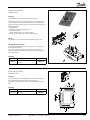
AKC 25H1
AKC 25H1 is a capacity controller for compressors and condensors.
AKC 25H1 controls up to nine stages distributed between the
compressor and/or condensing stage.
Description
• Possibility of connection to both main and relief stages of
identical sizes.
• Neutral zone adjustment of suction pressure and condensing
pressure.
Application example
Additional information!
Technical brochure: RC1J4
Function description: RC1JZ
22
RK0YG302
©
Danfoss
05/2007
AKC 25H1
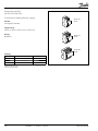
AKC 25H3
The control has the same functions as AKC 25H1, but can
additionally be used to control two independent refrigeration
circuits.
Description
• Neutral zone adjustment of suction pressure and condensing
pressure.
• PI regulation of condensing pressure.
• Regulation of condensing pressure as a function of outdoor
temperature
• Possibility of variable speed regulation of condenser fan or
connection of a relay module for further step-by-step coupling
of condenser steps
• Internal day/night clock
• Connection of display to show selected operating parameters
Application example
Additional information!
Technical brochure: RC1J4
Function description: RC8AH
AKC 25H3
RK0YG302
©
Danfoss
04/2007
23
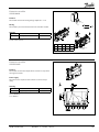
AKC 25H5
The controller has the same functions as the AKC 25H1 but also
offers the possibility of controlling the different stage intervals
and speed adjustment. This ensures even better capacity
adaptation to the actual load.
Description
• Possibility of connection to both main and relief stages of
different sizes.
• PI regulation of suction and condensing pressure.
• Possibility of connection to VLT frequency converter for the
speed regulation of a compressor stage or condensing stage.
Further functions
• Regulation of condensing pressure as a function of outdoor
temperature
• Internal day/night clock
• Possibility of heat recovery or liquid injection in suction line
Connection of display to show selected operating parameters
• Possibility of connecting external energy monitoring equipment
so that the maximum coupled compressor capacity can be
limited
Application example
Additional information!
Technical brochure: RC1J4
Function description: RC1J5
24
RK0YG302
©
Danfoss
05/2007
AKC 25H5
Water chiller control
AKC 25H7
AKC 25H7 is a complete brine cooler control unit that has been
developed for indirect refrigerating systems in supermarkets.
The controller’s main function is to control compressors and
condensers in such a way that the required brine temperature is
maintained on the cold and warm side of the compressor system.
The controller contains all the functions required for the control of
a brine cooler:
• The cold brine temperature can be controlled according to the
shop temperature or the enthalpy
• Day/night programmes for the temperature reference (economy
control)
• Alarm limits and delays on forward and return flow temperatures
• Capacity control and monitoring of compressors distributed on
one or two groups
• Sequential control or time equalisation of compressors
• Frost cutout for monitoring of suction pressure P0
• Peak load limitation via external signal
• Central defrost control or weekly programme (stop based on
temperature or time)
• Signal given when injection is permitted
• Control and monitoring of single pump or twin pump on cold
and warm brine
• Built-in rotation between twin pumps
• Automatic pump change when pump is defective
• Control and monitoring of air-cooled or brine-cooled condenser
• Condenser can be controlled based on pressure (Pc) or warm
brine temperature (S7)
• Monitoring of max. condensing pressure
• Step regulation or speed regulation of fans
• Condensing pressure can be controlled according to outdoor
temperature and an external voltage signal
• Control of heat recovery temperature with built-in safeguard
against too low condensing pressure
• Heat recovery temperature can be controlled according to
outdoor temperature and an external voltage signal
• Monitoring of the compressors’ safety circuit can be
supplemented with alarm module type AKC 22H
Application example
Additional information!
Function description: RC1NP
AKC 25H7
RK0YG302
©
Danfoss
05/2007
25
AK-CH 650
Application
AK-CH 650 is for capacity control of chillers.
The controller can control compressors, fans, pumps, defrosting
sequences and start/stop injection in a heat exchanger.
(If complete dry refrigeration control is required including a threeway valve for the condenser, AK-PC 420 is recommended.)
Advantages
• Optimisation of charge temperature from the refrigeration area
which is used most
• Optimisation of condenser in relation to ambient temperature
• Flexible hardware platform with extension modules
• Fast set-up using pre-defined set-ups.
Control
• Compressor capacity is controlled via the charge temperature
S4. The reference can either be over-ridden via day/night signal,
an external 0-10 V signal, temperature signal or optimised automatically from the refrigeration area which is used most
• Fan capacity is controlled either via the condensing pressure Pc
or a media temperature S7 (dry refrigeration). The reference can
be optimised via ambient temperature and changed during heat
recovery.
• The Ss and Sd sensors are used for monitoring of overheating of
the suction pipe and pressure pipe temperature respectively.
Additional functions
• Control of up to 6 compressors
• Compressors of the same or different size
• Speed control of one or two compressors
• Equalising of operating time between compressors
• Anti-cycle timers for each compressor
• Up to 6 safety inputs per compressor
• Capacity limit of compressors via 2 digital inputs
• Step or speed control of up to 8 fans
• Monitoring of fans
• Signal for start/stop of injection in heat exchangers
• Control and monitoring of 2 twin pumps. Automatic rotation
• Defrost control according to internal schedule, digital input or
network signal
• Defrost stop according to temperature and/or time
• Alarm monitoring of low suction pressure P0 (frost protection),
high condensing pressure and high brine temperature.
• Monitoring of external frost protection
• 5 digital inputs for alarm monitoring
• 5 thermostats and pressure switches for monitoring/control
• 5 voltage inputs 0-10 V d.c. for signal monitoring
26
RK0YG302
©
Danfoss
05/2007
AK-CH 650
Example
Compressors
Compressor capacity is controlled by charge temperature S4 and
by suction pressure P0 as frost protection.
Three compressors are used with speed control on the first compressor. Pc is used for high pressure monitoring.
Pumps
Two twin pumps controlled by time-based rotation. The pumps
are monitored by a pressure difference pressure switch. If pump
errors occur, automatic switch to the other pump takes place.
Condenser/dry cooler
AK-PC 420 is used for:
• Fan speed control
• Three-way valve control
• Pump control
• Heat recovery control
• Capacity control from signal from condensing pressure Pc.
Injection
EKC 316A is used for optimum control of superheat.
The valve is an expansion valve with a step motor.
Defrosting
For defrosting the compressors are stopped and the connected
refrigeration areas are defrosted by circulation of brine. Defrosting is stopped at S3 temperature with subsequent drip off delay
before the compressors are restarted.
Additional information!
Manual: RS8ER
AK-CH 650
RK0YG302
©
Danfoss
04/2007
27
Dry cooler
AK-PC 420
Application
AK-PC 420 is a complete capacity control of a dry cooler including
fans, three-way valve, pumps and heat recovery.
Advantages
• Complete capacity control of dry cooler
• Option of choosing control sensor (S7/Pc and/or S8)
• Control according to one loop or two loop principles for optimum operation on all system types
• Fan speed control
• Fan connection according to sequential or rotational operation
• Reference according to ambient temperature
Control
• Capacity control according to condensing pressure Pc or brine
return temperature S7.
• Reference temperature according to fixed settings with option
of overriding via ambient temperature or external 0-10 V signal.
Separate reference for heat recovery.
• For one-loop control a capacity adjustment of the three-way
valve and fans is carried out via Pc or S7.
• For two-loop control individual capacity adjustment of the two
circuits is carried out: three-way valve via Pc/S7 and fans via S8.
This ensures that even difficult systems with long tubes can be
handled optimally.
Functions
• Control and monitoring of max. 6 fans via step or speed control
• Sequential or rotational fan operation
• Three-way valve control
• Over-riding of reference temperature via ambient temperature
Sc3 or 0-5 V d.c. signal
• Separate reference temperature for heat recovery with overriding via 0-5 V d.c. signal
• Input for start and outlet for activation of heat recovery
• Control and monitoring of two twin pumps with rotational
operation
• Safety function for high condensing pressure
• Alarm relay
• External control start/stop
Additional information!
Manual: RS8EL
Operation
All operation takes place either via data communication or by
connection of a display of the type EKA 164. Extra readout via
display of the type EKA 163.
28
RK0YG302
©
Danfoss
05/2007
AK-PC 420
RK0YG302
©
Danfoss
04/2007
29
Liquid injection in the suction line
EKC 319A
Application
The controller limits the pressure gas temperature in compressors
by opening up for liquid injection in the suction line.
Control
A temperature sensor will register the discharge gas temperature.
If the temperature reaches the set temperature value, opening of
the valve will be commenced.
A PI regulation will adapt the opening degree of the valve so that
the temperature will be limited.
Temperature sensor
Type AKS 21 can be used. It can stand the high temperature.
Valve
If the liquid injection is carried out directly in the suction line an
expansion valve type AKV, or a type AKVA (for NH3), is used. The
capacity requirement is determined by the size of the valve. If the
compressor is provided with a connection for liquid injection a
pulse solenoid valve type EVRP is used in the liquid supply.
Alarm function
The controller will sound an alarm if the set alarm limit is exceeded.
The alarm will activate the alarm relay.
30
RK0YG302
©
Danfoss
05/2007
EKC 319A
Menu survey
SW = 1.1x
Function
Para- Min.
meter
Max.
Fac.
setting
Normal display
Read the measured discharge gas temperature
-
°C
If you wish to see the actual opening degree,
give the lower button a brief push
-
%
If you wish to set the temperature reference
you obtain access by pushing both buttons
simultaneously
-
-70°C
160°C
Data
Supply voltage
Power consumption
125
Input signal
Display/Control
Select unit (0=°C, 1=°F)
r05
0
1
0
Start/stop of regulation
r12
OFF
ON/on
on
Temperature sensor
Pt 1000 ohm/0°C
Enclosure
Contact function start/stop of regulation
AC-1: 4 A (ohmic)
SPST
AC-15: 3 A (inductive)
AKV, AKVA or EVRP via 24 a.c. Pulse-Width
Modulating output
Possible to connect a data communication
module
0 - 55°C, during operation
-40 - 70°C, during transport
20 - 80% Rh, not condensed
No shock influence/vibrations
IP 20
Weight
300 g
Alarm relay
Valve connection
Alarm
24 V a.c. +/-15% 50/60 Hz, 60 VA
(the supply voltage is galvanically separated from
the input and output signals. Input/output are
not individual galvanic isolated)
Controller
5 VA
20 W coil for AKV/A
55 VA
Coil for EVRP
40 VA
Data communication
Alarm limit
A16
-50°C
150°C
135
Time delay for alarm
A17
0s
999 s
0
Function of the alarm relay when the temperature exceed the alarm limit
0: Alarm relay active
1: Alarm relay not active
A19
0
1
1
Proportionale factor Kp
n04
0,5
30
15
I: Integration time Tn
n05
60 s
600
s/Off
120
Montage
DIN Rail
Periode time
n13
3s
10 s
3
Display
LED, 3-digits
Terminals
max. 2.5 mm2 multicore
Approvals
EU Low Voltage Directive and EMC demands re
CE-marking complied with.
LVD-tested acc. to EN 60730-1 and EN 60730-2-9
EMC-tested acc. to EN50081-1 and EN 50082-2
Environments
Regulating parameters
Miscellaneous
Controller's address
o03*
0
119
-
ON/OFF switch (service-pin message)
o04*
OFF
ON
-
Set supply voltage frequency
o12
0/50
Hz
1/60
Hz
50
Select the showing of the "normal display":
0: Discharge gas temperature is shown
1: Valve’s opening degree is shown
o17
0
1
0
Manual control of outputs:
OFF: No manual control
1: Valve output put in pos. ON
2: Alarm relay activated (cut out)
o18
OFF
2
off
Service
Read discharge gas temperature
u01
°C
Read temperature reference
u02
°C
Read status of input DI
u10
Read valve’s opening degree
u24
%
*) This setting will only be possible if a data communication module has been
installed in the controller.
Factory setting
If you need to return to the factory-set values, it can be done in this way:
- Cut out the supply voltage to the controller
- Keep both buttons depressed at the same time as you reconnect the supply voltage
Ordering
Type
Function
Ordering
EKC 319A
Temperature controller
084B7251
EKA 175
Data communication module
(accessories), (RS 485 modul)
084B7093
The installation of data communications must comply with the requirements described in literature sheet no. RC8AC
Additional information!
Manual: RS8EB
EKC 319A
RK0YG302
©
Danfoss
04/2007
31
Speed control of compressor and condenser
Introduction
AKD-Variable Speed Drives are engineered to optimize performance in your refrigeration system and as a part of ADAP-KOOL®
system are dedicated to the following refrigeration applications:
• Pack or Compressor Control
• Pumps
• HVAC (Centrifugal fans and pumps)
• Condensers
AKD-Variable Speed Drives offer a variety of benefits in the refrigeration systems:
Energy savings
The continuous variable speed control by AKD makes intelligent
capacity control possible. It creates stability while balancing the
capacity to the actual load, resulting in improved system COP and
significant energy savings. Intelligent compressor and condenser
fan control is a “must” in any optimised refrigeration system.
Improved control and product quality
Stabilizing and optimising pressures result in less ice formation
on evaporators producing optimal airflow, air temperature and
reduced temperature “pull-down” resulting in improved product
quality. A stabilized condensing pressure will result in less migration of refrigerant thereby reducing the amount of refrigerant
needed in the system.
Noise reduction in many ways
AKD variable speed technology reduces the acoustic noise level of
condenser fan motors significantly.
AKD also protects the environment against electrical noise by
having an excellent RFI filter in accordance with international
standards (EN 55011 class 1A or1B).
Longer lifetime
Continuous control with AKD reduces the total number of start/
stops required, as well as the mechanical wear of rotating components.
Easy to install and use
AKD eliminates the need for special starting equipment due to
the inherent built-in current reduction. It offers motor protection
against overload and high temperature conditions and has builtin crank case heater function. It is easy to integrate the AKD into
your facility due to the time saving, user-friendly set-up and installation procedures. In addition, the built-in PI controller provides
direct control of specific applications.
32
RK0YG302
©
Danfoss
ADAP-KOOL® system integration
Thanks to LON module for data communication AKD-Variable
Speed Drives are easily integrated into ADAP-KOOL® system
making possible:
• Monitoring of the energy consumption
• Alarm monitoring and alarming
• Monitoring of actual capacity of pumps, compressors and fans
• Remote access to data via modem/gateway
• Remote commissioning through up/download of parameter files,
significantly simplifying the installation
AKD can be easily applied with the standard EKC 531 and AK-PC
Pack controller for infinitely variable speed control and energy
optimisation of Condenser fans and/or Compressors, matching
required capacity to load variations.
In HVAC applications around the refrigeration system, they can be
applied to AHU fans and circulation pumps, maximising energy
savings and improving system efficiency.
05/2007
AKD 2800
AKD 2800
AKD 2800 is a frequency converter for use in refrigeration system
in book form design and with local control panel. It has an IP 20
enclosure and is available in versions with or without RFI filter.
(Please note that Danfoss recommend that for Food Retail
applications the drive is always purchased complete with the RFI
filter.)
A LON module for data communication with ADAP-KOOL® is
available as accessory - see section “AKD Variable Speed Drives,
accessories and spare parts".
For single phase versions, please contact Danfoss.
AKD 2800 Variable Speed Drives 220-240 V
AKD 2800 Serie 220-240V is available from 0.37 kW to 3.7 kW.
AKD 2800 Variable Speed Drives 380-440 V
AKD 2800 Serie 380-440V is available from 0.55 kW to 18.5 kW.
In the table only types with RFI filter are listed.
A LON module for data communication with ADAP-KOOL® is
available as accessory - see section “AKD Variable Speed Drives,
accessories and spare parts".
Type
Rated
Power
[kW]
AKD 2805
AKD 2807
AKD 2811
AKD 2815
AKD 2822
AKD 2830
AKD 2840
AKD 2855
AKD 2875
AKD 2880
AKD 2881
AKD 2882
0.55 kW
0.75 kW
1.1 k W
1.5 kW
2.2 kW
3 kW
4 kW
5.5 kW
7.5 kW
11 kW
15 kW
18.5 KW
AKD 2800
Output. current
160% cont.
For condenser fan,
HVAC and compresor
applications
1.7 A
2.1 A
3A
3.7 A
5.2 A
7A
9.1 A
12 A
16 A
24 A
32 A
37.5 A
Weight
Code No.
3.00
3.10
3.10
3.10
4.20
4.20
4.30
6.50
6.50
18.50
18.50
18.50
175B4538
175B4539
175B4540
175B4541
175B4542
175B4543
175B4544
175B4545
175B4546
175B4547
175B4548
175B4549
RK0YG302
©
Danfoss
04/2007
33
AKD 5000
AKD 5000 is a frequency converter for use in refrigeration systems
in compact cabinet design, with a local control panel. It is
available in versions with IP 20 or IP 54 enclosure and is available
in versions with RFI filter.
Variable Speed Drives, 220-240 V
AKD 5000 Series 220-240 V is available from 0.75 kW to 75 kW.
ADAP-KOOL® LON module
For AKD 5000 versions supplied without LON module an optional
module is available - see section “AKD Variable Speed Drives,
accessories and spare parts”.
For other versions and configurations, please contact Danfoss.
Variable Speed Drives 380-440 V
AKD 5000 Series 380-440 V is available from 0.75 kW to 75 kW.
ADAP-KOOL® LON module
AKD 5000 with build in LON module is available.
For AKD 5000 versions supplied without LON module an optional
module is available - see section “AKD Variable Speed Drives,
accessories and spare parts”.
For other versions and configurations, please contact Danfoss.
Type
Rated
Power
[kW]
Outp. curr. 160% cont.
Compressor Application
Output. curr. 110% cont.
condenser fan or HVAC
fan/pump applications
AKD 5001
0.75 kW
2.2 A
2.2 A
AKD 5002
1.1 kW
2.8 A
2.8 A
AKD 5003
1.5 kW
4.1 A
4.1 A
AKD 5004
2.2 kW
5.6 A
5.6 A
AKD 5005
3 kW
7.2 A
7.2 A
AKD 5006
4 kW
10 A
10 A
AKD 5008
5.5 kW
13 A
13 A
AKD 5011
7.5 kW
16 A
16 A
AKD 5016
11 kW
24 A
32 A
AKD 5022
15 kW
32 A
37.5 A
AKD 5027
18.5 kW
37.5 A
44 A
AKD 5032
22 kW
44 A
61 A
AKD 5042
30 kW
61 A
73 A
AKD 5052
37 kW
73 A
90 A
AKD 5062
45 kW
90 A
106 A
AKD 5072
55 kW
106 A
147 A
AKD 5102
75 kW
147 A
177 A
RFI filter
Class 1B
Class 1A
Class 1B
Class B
Weight
[Kg]
Encl.
8.20
12.60
9.00
13.30
9.00
13.40
9.00
13.80
9.40
12.30
11.10
14.00
11.20
14.00
11.80
16.50
24.00
45.90
25.70
44.20
29.20
45.60
31.00
56.90
43.30
60.10
46.10
61.90
45.00
45.00
50.00
50.00
50.00
IP 20
IP 54
IP 20
IP 54
IP 20
IP 54
IP 20
IP 54
IP 20
IP 54
IP 20
IP 54
IP 20
IP 54
IP 20
IP 54
IP 20
IP 54
IP 20
IP 54
IP 20
IP 54
IP 20
IP 54
IP 20
IP 54
IP 20
IP 54
IP 20
IP 54
IP 54
IP 20
IP 54
Code No.
Incl. RFI
Incl. RFI
Incl. LON *
178B4648
178B4706
178B4649
178B4707
178B4650
178B4708
178B4651
178B4709
178B4652
178B4710
178B4653
178B4711
178B4655
178B4712
178B4654
178B4713
178B4656
178B4714
178B4657
178B4715
178B4658
178B4716
178B4659
178B4717
178B4660
178B4718
178B4661
178B4719
178B4662
178B4720
178B7377
178B7117
178B7379
178B4663
178B4721
178B4664
178B4722
178B4665
178B4723
178B4666
178B4724
178B4667
178B4725
178B4668
178B4726
178B4669
178B4727
178B4670
178B4728
178B4671
178B4729
178B4672
178B4730
178B4673
178B4731
178B4674
178B4732
178B4676
178B4733
178B4677
178B4734
178B4678
178B4735
178B7378
178B7381
178B4362
*) With LON module for ADAP-KOOL® data communication
34
RK0YG302
©
Danfoss
05/2007
AKD 5000
Accessories for AKD
Type
Terminal cover
Code No.
195N1900
195N1901
195N1902
195N2179
195N2180
Top cover IP 21
195N2181
Filter modul
LON Interface
Accessories for AKD
195N2182
195N3103
195N2100
175Z4362
Description
AKD 2803-2815, 200-240 V,
AKD 2805-2815, 380-480 V
AKD 2822-2840, 200-240 V,
AKD 2822-2840, 380-480 V
AKD 2840, 200-240 V,
AKD 2855-2875, 380-480 V
AKD 2803-2815, 200-240 V,
AKD 2805-2815, 380-480 V
AKD 2822, 200-240 V,
AKD 2822-2840, 380-480 V
AKD 2840, 200-240 V,
AKD 2855-2875, 380-480 V
AKD 2880-2882, 380-480 V
VLT 2803-2875
AKD 2800 series
AKD 5000 series
RK0YG302
©
Danfoss
04/2007
35
RGE
RGE, Variable Speed Control, is used for fan speed control, and is
available in single and three phase versions. RGE is a simple and
efficient all-in-one pressure sensor and fan speed control, featuring a reliable sensing mechanism using bellows. RGE is easy to
install and set up, and can be used for a large number of refrigerants: R 22, R 407C, R 404A, R 134a and R 410A. RGE is CE/EMC
approved.
Type
Code No.
Refrigerants
RGE-Z3T4-7DS
061H3050
RGE-X3R4-7DS
061H3006
RGE-Z1N4-5H
061H3013
RGE-Z1L4-7DS
061H3045
RGE-Z1N4-7DS
061H3005
RGE-Z3R4-7DS
061H3003
RGE-Z1P4-7DS
061H3008
RGE-Z1Q4-7DS
061H3009
RGE-Z1L6-7DS
RGE-Z1N6-7DS
RGE-Z3R6-7DS
RGE-Z1P6-7DS
RGE-Z3T6-7DS
RGE-Z1Q6-7DS
RGE-X3R6-7DS
061H3048
061H3021
061H3027
061H3022
061H3051
061H3023
061H3028
R22/R404A/
R407C
R22/R404A/
R407C
R407C/R404A/
R134a/R22
R407C/ R404A/
R134a/R22
R407C/ R404A/
R134a/R22
R407C/ R404A/
R134a/R22
R407C/ R404A/
R134a/R22
R407C/ R404A/
R134a/R22
R410A
R410A
R410A
R410A
R410A
R410A
R410A
36
RK0YG302
Motor rating
[A]
0.2-7 A
Voltage
[V]
200-240
No. of
phases
3
Current
[A]
7A
Adj. range
[bar]
116-406 psig/ 8-28 bar
P-band
[bar]
4 bar
Factory
setting [bar]
16 bar
0.2-5 A
380-415
3
5A
116-406 psig/ 8-28 bar
4 bar
16 bar
0.2-2 A
200-240
1
2A
116-406 psig/ 8-28 bar
4 bar
19 bar
0.2-2 A
200-240
1
2A
116-406 psig/ 8-28 bar
6 bar
19 bar
0.2-4 A
200-240
1
4A
116-406 psig/ 8-28 bar
4 bar
19 bar
0.2-5 A
200-240
3
5A
116-406 psig/ 8-28 bar
4 bar
16 bar
0.2-6 A
200-240
1
6A
116-406 psig/ 8-28 bar
4 bar
19 bar
0.2-8 A
200-240
1
8A
116-406 psig/ 8-28 bar
4 bar
19 bar
0.2-2 A
0.2-4 A
0.2-5 A
0.2-6 A
0.2-7 A
0.2-8 A
0.2-5 A
200-240
200-240
200-240
200-240
200-240
200-240
380-415
1
1
3
1
3
1
3
2A
4A
5A
6A
7A
8A
5A
16-39 bar/232-566 psig
16-39 bar/232-566 psig
16-39 bar/232-566 psig
16-39 bar/232-566 psig
16-39 bar/232-566 psig
16-39 bar/232-566 psig
16-39 bar/232-566 psig
9 bar
8 bar
8 bar
8 bar
8 bar
8 bar
8 bar
32 bar
32 bar
32 bar
32 bar
32 bar
32 bar
32 bar
©
Danfoss
05/2007
RGE
RK0YG302
©
Danfoss
04/2007
37
Evaporator controls and thermostatic expansion valves
Introduction
Thermostatic expansion valves are used in traditional refrigeration
systems and refrigeration appliances with limited possibility
of energy savings where injection of refrigerant liquid into
evaporator is controlled by the refrigerant superheat. Therefore,
thermostatic expansion valves are especially suitable for liquid
injection in ”dry“ evaporators where the superheat at the
evaporator outlet is proportional to the evaporator load.
The evaporator controls for regulating refrigeration appliances
with thermostatic expansion valves or compressor are capable
of regulating different types of functions in order to fulfil any
evaporator control demand. The controls have functions for
regulating/monitoring temperature, defrosting, doors, rail
heating, light and fan operation.
With remote communication as a part of ADAP-KOOL®
refrigeration control system, evaporator controls comprise
monitoring and control of display cases and cold rooms including
alarm monitoring improving performance of refrigeration system.
EKC controllers 102, 202 and AK-CC 210 improve operation
routines with cost optimised design for most common
applications
Characteristic of the EKC controllers 102, 202 and AK-CC 210 is
easy panel installation due to the integrated mounting brackets.
The controllers have high-effect 16A relays which enable direct
connection of heavy loads, such as compressor or defrost.
Also, all the controllers have built-in 230 V a.c. supply and
supports different types of sensors (Pt 1000, NTC and PTC).
The controllers have enhanced life-time and reliability thanks to
IP 65 rating, so no water spray can damage it. Copy key with room
for 25 controller setups ensures a fast and easy programming.
Factory calibration ensures that the measuring accuracy of
controllers in combination with a Pt 1000 sensor is better than
required in EN 441-13 without any subsequent calibration
ensuring compliance with HACCP.
EKC 301 as DIN-rail mounting controller is designed for room
temperature control via pump down or compressor start/stop.
EKC 301 is controlling compressor, fan, defrost and alarm and
it replaces several traditional controllers and defrost clocks due
optional Real time clock module.
There are other controllers like AKC 121 which are used in
applications where TEV-valves are used but additional hardware
or functions are required. The controls are capable of regulating
one or more evaporators, depending on the type of controls. The
controls are capable of regulating simultaneously temperature,
defrosting, door frame, rail heat, light and fan.
38
RK0YG302
©
Danfoss
05/2007
ADAP-KOOL® evaporator controllers offer three levels of control
for different application demands.
Supervisory control &
Optimised control with
EKC 414A1/514B /
AKC 1xx & AK-CC
Supervisory control
with
EKC 301/202/AK-CC 450
Local control &
alarm with
EKC 100, 102
This section
Comparison of controls in this section
Temperature control of refrigeration appliances and cold storage rooms
Type
Relays
Compressor/ Valve, Amp:
Defrost, Amp:
Fan, Amp:
Alarm/Light/Aux/, Amp:
Second compressor, Amp:
Analogue inputs
Digital inputs
Pt 1000 sensor
PTC and NTC Sensor
Copy key as option
Data communication as option
Real time clock
HACCP compliance via system
HACCP function
Application selection switch
Weighted sensor output
Coordinated defrost
Coordinated defrost via system
EKC
100
1
10 (SPST)
EKC
102A
1
10
EKC
102B
2
10 10
EKC
102C
2
10 10
10
10
10
10
2
1
1
2
1
2
1
EKC
102D
3
10
10
6
2
1
EKC
202A
2
10 10
4
EKC
202B
3
10
10
6
4
2
1
2
1
NTC
2
1
EKC
202C
4
10
10
6
4
EKC
202D
4
10
10
6
4
AK-CC
210
4
10
10
6
4
2
1
3
2
3
2
2
1
YES
YES
AK-CC
450
6
½
4
4
4
4
6
3
EKC
301
4
6
6
6
4
2
1
YES
YES
YES
YES
YES
YES
YES
YES
YES
YES
YES
YES
Current specifications and relay sizes:
10 = 10 (6) A. The relay is a 16 A relay.
6 = 6 (3) A. The relay is a 8 A relay.
4 = 4 (1) A. The relay is a 8 A relay.
PCB paths and derating mean that the specified values may not be exceeded.
Temperature control with high accuracy
Type
EKC 361
EKC 368
Code No.
084B7060
084B7079
Application
Cold storage rooms for e.g. fruit
Work areas in the food industry
Delicatessen appliances
Cold storage rooms for meat product
RK0YG302
©
Danfoss
04/2007
39
Temperature control
EKC 100
Introduction
The controller is used for temperature control of refrigeration
plant.
Operation, setting and programming are optimised and simplified
as much as possible.
The controller is designed so that temperature control and
defrost control can be made via pump down or start/stop of the
compressor.
Menu survey
SW = 1.1X
Parameter
Function
Normal operation
Temperature (set point)
Thermostat
Differential
Display adjust
Compressor
Min. ON-time
Min. OFF-time
Defrost
Defrost stop temperature
Interval between defrost
starts
Max. defrost duration
Displacement of time on
cutin of defrost at start-up
Miscellaneous
Delay of output sigal after
start-up
Fault code
Sensor error
Code
Min.
value
Max.
value
Factory
setting
---
-60°C
50°C
0°C
r1
r4
1K
-20 K
20 K
20 K
2K
0K
c1
c2
0 min.
0 min.
30 min.
30 min.
0 min.
0 min.
d2
d3
0°C
0 hours
25°C/off
48 hours
25°C/off
8 hours
d4
d5
0 min.
0 min.
99 min.
15 min.
45 min.
0 min.
o1
0 min.
15 min.
0 min.
Er
Regulation starts when the voltage is on.
40
RK0YG302
©
Danfoss
05/2007
EKC 100
Technical data
Supply voltage
Sensor connection
230 V a.c. +10/-15 %. 0.5 VA
NTC 5000 ohm/25°C. e.g. type EKS 211
Measuring
range
Accuracy
Controller
NTC sensor
Display
Light-emitting
diode (LED)
Electrical connection cable
Relay
-60 to +50°C
±1 K below -0°C
±0.5 K between -0 to +10°C
±1 K above +10°C
±0.5 K at 0°C
LED, 2 digits
Indicates cut-in relay
Max.1,5 mm2 multi-core cable on supply and relays.
Max. 1 mm2 on sensors
Terminals are mounted on the circuit board
CE
UL
Rated voltage 250 V
240 V a.c.
10 A Resistive
I
10 (6) A
5FLA 30LRA
The relay is a 16 A relay, but conductor lanes and
derating mean that 10 (6) A must not be exceeded
Environments
Enclosure
Approvals
0 - 55°C, during operation
-40 - 70°C, during transport
20 - 80% Rh, not condensed
No shock influence/vibrations
IP 20/IP 65 from front.
Buttons are imbedded in the front.
EU Low Voltage Directive and EMC demands re CEmarking complied with
LVD tested acc. EN 60730-1 and EN 60730-2-9, A1, A2
EMC tested acc. EN50082-1 and EN 60730-2-9, A2
Electrical connection
(115 V a.c.)
NTC - temperature sensor type EKS 211:
Ordering
Type
EKC 100
Function
Voltage
Number
Code No.
Temperature
controller
230 V
60 pcs
084B8610
115 V
60 pcs
084B8611
Additional information!
Data sheet: RD8AZ
EKC 100
RK0YG302
©
Danfoss
04/2007
41
EKC 102
Application
• The controller is used for temperature control refrigeration appliances and cold room
• Defrost control
• For front panel mounting
Advantages
• Integrated refrigeration-technical functions
• Defrost on demand in 1:1 systems
• Buttons and seal imbedded in the front
• IP 65 enclosure from the front panel
• Can control two compressors
• Digital input for either:
- Door alarm
- Defrost start
- Start/stop of regulation
- Night operation
- Change-over between two temperature reference
- Case cleaning function
• Instant programming via programming key
• HACCP
Factory calibration that will guarantee a better measuring
accuracy than stated in the standard EN 441-13 without
subsequent calibration (Pt 1000 ohm sensor)
Control
The controller contains a temperature control where the signal
can be received from one temperature sensor.
The sensor is placed in the cold air flow after the evaporator or in
the warm air flow just before the evaporator.
The controller controls the defrost with either natural defrost or
electric defrost. Renewed cutin after defrost can be accomplished
based on time or temperature.
A measurement of the defrost temperature can be obtained
directly through the use of an S5 sensor.
One, two or three relays will cut the required functions in and out
– the application determines which:
• Refrigeration (compressor or solenoid valve)
• Defrost
• Alarm
• Refrigeration 2 (compressor 2)
• Fan
The different applications are described on next page.
The series
There are four controllers in the series:
A-model for simple regulation
B-model where an alarm function and possibly also a digital input
will be required
C-model where the defrost temperature also enjoys top priority
D-model with fan function, change-over between temperature
reference and case cleaning function
All these four controllers are without data communication.
If data communication or additional functions are required, we
refer you to the EKC 202 or AK-CC 210 series.
42
RK0YG302
©
Danfoss
05/2007
EKC 102
EKC 102A
Controller with one relay output and one temperature sensor.
Temperature control at start/stop of compressor.
Natural defrost at stop of compressor.
Instead of the compressor a solenoid valve may of course be
connected in the liquid line.
Heating function
The controller can also be used as a simple on/off thermostat for
heating applications.
EKC 102B
Controller with two relay outputs, extra temperature sensor and
digital input.
Relay output 2 can be used for alarm function or for cutin and
cutout of a refrigeration step 2.
The extra temperature signal can be used for product sensor or for
condenser sensor with alarm function.
The digital input can be used for door alarm, defrost start, start/
stop of refrigeration or for night signal.
EKC 102C
Controller with two relay outputs, extra temperature sensor and
digital input.
Relay output 2 can be used for electric defrost or for an alarm
function.
Temperature signal 2 can be used for defrost stop based on
temperature or for product sensor.
In a 1:1 sysem and with the sensor mounted on the evaporator
the controller will be able to use the ”defrost on demand”
function. The function will start a defrost when the evaporator’s
refrigeration capacity drops due to icing-up.
The digital input can be used for door alarm, defrost start, start/
stop of refrigeration or for night signal.
EKC 102D
Controller with three relay outputs, two temperature sensors and
digital input.
Temperature control at start/stop of compressor/solenoid valve
Defrost sensor
Electrical defrost /gas defrost
Relay output 3 is used for control of fan.
EKC 102
RK0YG302
©
Danfoss
04/2007
43
Menu survey EKC 102A
SW = 1.1x
Parameters
Function
Normal operation
Temperature (set point)
Thermostat
Differential
Max. limitation of setpoint setting
Min. limitation of setpoint setting
Adjustment of temperature indication
Temperature unit (°C/°F)
Correction of the signal from Sair
Manual service (-1), stop regulation (0), start regulation (1)
Compressor
Min. ON-time
Min. OFF-time
Compressor relay must cutin and out inversely
(NC-function)
Defrost
Defrost method (0=none/1=natural)
Defrost stop temperature
Interval between defrost starts
Max. defrost duration
Displacement of time on cutin of defrost at start-up
Defrost sensor (0=time, 1=Sair)
Defrost at start-up
Miscellaneous
Delay of output signals after start-up
Access code
Used sensor type (Pt /PTC/NTC)
Refrigeration or heat (rE=refrigeration, HE=heat)
Display step = 0.5 (normal 0.1 at Pt sensor)
Save the controllers present settings to the programming
key. Select your own number.
Load a set of settings from the programming key (previously saved via o65 function)
(Can only be set when regulation is stopped (r12=0)
Replace the controllers factory settings with the present
settings
Service
Status on relay
Can be controlled manually, but only when r12=-1
Codes
Min.value
Max.value
Factory
setting
---
-50°C
99°C
2°C
r01
r02
r03
r04
r05
r09
r12
0,1 K
-49°C
-50°C
-20 K
°C
-10 K
-1
20 K
99°C
99°C
20 K
°F
10 K
1
2K
99°C
-50°C
0K
°C
0K
1
c01
c02
c30
0 min
0 min
OFF
30 min
30 min
On
0 min
0 min
OFF
d01
d02
d03
d04
d05
d10
d13
0
0°C
0 hours
0 min
0 min
0
no
1
25°C
48 hours
180 min
240 min
1
yes
1
6°C
8 hours
45 min
0 min
0
no
o01
o05
o06
o07
o15
o65
0s
0
Pt
rE
no
0
600 s
100
ntc
HE
yes
25
5s
0
Pt
rE
no
0
o66
0
25
0
o67
OFF
On
OFF
u58
Regulation starts when the voltage is
on.
Fault code display
A45
Standby mode
Alarm code display
Fault in controller
E1
E29
Sair sensor error
Status code display
S0
Regulating
S2
ON-time Compressor
S3
OFF-time Compressor
Refrigeration stopped by thermostat
S11
Defrost sequence. Defrosting
S14
S20
Emergency cooling
S32
Delay of output at start-up
non
The defrost temperature cannot be
displayed. There is no sensor
-dDefrost in progress/First cooling after
defrost
PS
Password required. Set password
Factory setting
If you need to return to the factory-set values, it can be done in this way:
- Cut out the supply voltage to the controller
- Keep upper and lower button depressed at the same time as you reconnect the supply voltage
44
RK0YG302
©
Danfoss
05/2007
EKC 102
Menu survey EKC 102B and EKC 102C
SW = 1.1X
Parameters
Function
Normal operation
Temperature (set point)
Thermostat
Differential
Max. limitation of setpoint setting
Min. limitation of setpoint setting
Adjustment of temperature indication
Temperature unit (°C/°F)
Correction of the signal from Sair
Manual service, stop regulation, start regulation (-1, 0, 1)
Displacement of reference during night operation
Alarm
Delay for temperature alarm
Delay for door alarm
Delay for temperature alarm after defrost
High alarm limit
Low alarm limit
High alarm limit for condenser temperature (o69)
Compressor
Min. ON-time
Min. OFF-time
Time delay for cutin of comp.2
Compressor relay must cutin and out inversely
(NC-function)
Defrost
Defrost method (0=none/1=natural)
Defrost stop temperature
Interval between defrost starts
Max. defrost duration
Displacement of time on cutin of defrost at start-up
Defrost sensor 0=time, (B:1=Sair.) (C: 1=S5, 2=Sair)
Defrost at start-up
Max. aggregate refrigeration time between two defrosts
Defrost on demand - S5 temperature’s permitted variation
during frost build-up. On central plant choose 20 K (=off )
Miscellaneous
Delay of output signals after start-up
Input signal on DI1. Function:
(0=not used. , 1= door alarm when open. 2=defrost start
(pulse-pressure). 3=ext.main switch. 4=night operation
Access code 1 (all settings)
Used sensor type (Pt /PTC/NTC)
Display step = 0.5 (normal 0.1 at Pt sensor)
Access code 2 (partly access)
Save the controllers present settings to the programming
key. Select your own number.
Load a set of settings from the programming key (previously saved via o65 function)
(Can only be set when regulation is stopped (r12=0)
Replace the controllers factory settings with the present
settings
Select application for Saux sensor (0=not used, 1=product
sensor, 2=condenser sensor)
Select application for S5 sensor (0=defrost sensor, 1=
product sensor)
Select application for relay 2: 1=compressor-2/defrost, 2=
alarm relay
Service
Temperature measured with Saux sensor
Temperature measured with S5 sensor
Status on DI1 input. on/1=closed
Status on relay for cooling
Can be controlled manually, but only when r12=-1
Status on relay 2
Can be controlled manually, but only when r12=-1
EKC
102B
EKC
102C
Min.value
Max.value
Factory
setting
---
-50°C
50°C
2°C
r01
r02
r03
r04
r05
r09
r12
r13
0,1 K
-49°C
-50°C
-20 K
°C
-10 K
-1
-10 K
20 K
50°C
49°C
20 K
°F
10 K
1
10 K
2K
50°C
-50°C
0K
°C
0K
1
0K
A03
A04
A12
A13
A14
A37
0 min
0 min
0 min
-50°C
-50°C
0°C
240 min
240 min
240 min
50°C
50°C
99°C
30 min
60 min
90 min
8°C
-30°C
50°C
c01
c02
c05
c30
0 min
0 min
0 sec
OFF
30 min
30 min
999 sec
On
0 min
0 min
5 sec
OFF
0
0°C
0 hours
0 min
0 min
0
no
0 hours
0K
1
25°C
48 hours
180 min
240 min
1 (2)
yes
48 hours
20 k
1
6°C
8 hours
45 min
0 min
0
no
8 hours
2K
o01
o02
0s
0
600 s
4
5s
0
o05
o06
o15
o64
o65
0
Pt
no
0
0
100
ntc
yes
100
25
0
Pt
no
0
0
o66
0
25
0
o67
OFF
On
OFF
o69
0
2
0
o70
0
1
0
1
2
1
Codes
d01
d02
d03
d04
d05
d10
d13
d18
d19
o71
*
1=Sair 1=S5
Comp. / Defrost/
Alarm
Alarm
u03
u09
u10
u58
u70
Regulation starts when the voltage is on.
Alarm code display
High temperature alarm
A1
A2
Low temperature alarm
A4
Door alarm
A45
Standby mode
Condenser alarm
A61
Fault code display
Fault in controller
E1
E27
S5 sensor error
E29
Sair sensor error
E30
Saux sensor error
Status code display
S0
Regulating
S2
ON-time Compressor
S3
OFF-time Compressor
Refrigeration stopped by main
S10
switch
S11
Refrigeration stopped by
thermostat
Defrost sequence. Defrosting
S14
Door open (open DI input)
S17
S20
Emergency cooling
S25
Manual control of outputs
S32
Delay of output at start-up
non The defrost temperature
cannot be displayed. There is
no sensor
-dDefrost in progress/First cooling after defrost
PS
Password required. Set
password
Factory setting
If you need to return to the factory-set values, it can be done in this way:
- Cut out the supply voltage to the controller
- Keep upper and lower button depressed at the same time as you reconnect the supply voltage
* 1=>EL if o71 = 1
EKC 102
RK0YG302
©
Danfoss
04/2007
45
EKC 102D
SW = 1.2X
Parameters
Function
Normal operation
Temperature (set point)
Thermostat
Differential
Max. limitation of setpoint setting
Min. limitation of setpoint setting
Adjustment of temperature indication
Temperature unit (°C/°F)
Correction of the signal from Sair
Manual service(-1), stop regulation(0), start regulation (1)
Displacement of reference during night operation
Activation of reference displacement r40
Value of reference displacement (can be activated by r39 or DI)
Alarm
Delay for temperature alarm
Delay for door alarm
Delay for temperature alarm after defrost
High alarm limit
Low alarm limit
Alarm delay DI1
High alarm limit for condenser temperature (o70)
Compressor
Min. ON-time
Min. OFF-time
Compressor relay must cutin and out inversely (NC-function)
Defrost
Defrost method (none/EL/gas)
Defrost stop temperature
Interval between defrost starts
Max. defrost duration
Displacement of time on cutin of defrost at start-up
Drip off time
Delay for fan start after defrost
Fan start temperature
Fan cutin during defrost
Defrost sensor (0=time, 1=S5, 2=Sair)
Defrost at start-up
Max. aggregate refrigeration time between two defrosts
Defrost on demand - S5 temperature’s permitted variation during
frost build-up. On central plant choose 20 K (=off )
Fans
Fan stop at cutout compressor
Delay of fan stop
Fan stop temperature (S5)
Miscellaneous
Delay of output signals after start-up
Input signal on DI1. Function:
0=not used. 1=status on DI1. 2=door function with alarm when
open. 3=door alarm when open. 4=defrost start (pulse-pressure).
5=ext.main switch. 6=night operation 7=change reference (activate
r40). 8=alarm function when closed. 9=alarm function when open.
10=case cleaning (pulse pressure). 11=Inject off when open.
Access code 1 (all settings)
Used sensor type (Pt /PTC/NTC)
Display step = 0.5 (normal 0.1 at Pt sensor)
Case cleaning. 0=no case cleaning. 1=Fans only. 2=All output Off.
Access code 2 (partly access)
Save the controllers present settings to the programming key. Select
your own number.
Load a set of settings from the programming key (previously saved
via o65 function) Can only be set when regulation is stopped (r12=0)
Replace the controllers factory settings with the present settings
Select application for S5 sensor (0=defrost sensor, 1= product sensor,
2=condenser sensor with alarm)
Service
Temperature measured with S5 sensor
Status on DI1 input. on/1=closed
Status on night operation (on or off ) 1=closed
Read the present regulation reference
Status on relay for cooling (Can be controlled manually, but only
when r12=-1)
Status on relay for fans (Can be controlled manually, but only when
r12=-1)
Status on relay for defrost. (Can be controlled manually, but only
when r12=-1)
Temperature measured with Sair sensor
46
RK0YG302
©
Codes
Min.value
Max.value
Factory
setting
---
-50°C
50°C
2°C
r01
r02
r03
r04
r05
r09
r12
r13
r39
r40
0,1 K
-49°C
-50°C
-20 K
°C
-10 K
-1
-10 K
OFF
-50 K
20 K
50°C
49°C
20 K
°F
10 K
1
10 K
on
50 K
2K
50°C
-50°C
0.0 K
°C
0K
1
0K
OFF
0K
A03
A04
A12
A13
A14
A27
A37
0 min
0 min
0 min
-50°C
-50°C
0 min
0°C
240 min
240 min
240 min
50°C
50°C
240 min
99°C
30 min
60 min
90 min
8°C
-30°C
30 min
50°C
c01
c02
c30
0 min
0 min
0/OFF
30 min
30 min
1/on
0 min
0 min
0/OFF
d01
d02
d03
d04
d05
d06
d07
d08
d09
d10
d13
d18
d19
no
0°C
0 hours
0 min
0 min
0 min
0 min
-15°C
no
0
no
0 hours
0K
gas
25°C
48 hours
180 min
240 min
60 min
60 min
0°C
yes
2
yes
48 hours
20 K
EL
6°C
8 hours
45 min
0 min
0 min
0 min
-5°C
yes
0
no
0 hours
20 K
F01
F02
F04
no
0 min
-50°C
yes
30 min
50°C
no
0 min
50°C
o01
o02
0s
0
600 s
11
5s
0
o05
o06
o15
o46
o64
o65
0
Pt
no
0
0
0
100
ntc
yes
2
100
25
0
Pt
no
0
0
0
o66
0
25
0
o67
o70
OFF
0
On
2
OFF
0
u09
u10
u13
u28
u58
Alarm code display
High temperature alarm
A1
A2
Low temperature alarm
A4
Door alarm
A15
DI 1 alarm
A45
Standby mode
A59
Case cleasning
Condenser alarm
A61
Fault code display
Fault in controller
E1
E27
S5 sensor error
E29
Sair sensor error
Status code display
S0
Regulating
S2
ON-time Compressor
S3
OFF-time Compressor
S4
Drip-off time
Refrigeration stopped by main
S10
switch
S11
Refrigeration stopped by
thermostat
S14
Defrost sequence. Defrosting
Defrost sequence. Fan delay
S15
Refrigeration stopped because
S16
of open DI input
Door open (open DI input)
S17
S20
Emergency cooling
S25
Manual control of outputs
S29
Case cleaning
S32
Delay of output at start-up
non The defrost temperature cannot be displayed. There is stop
based on time
-dDefrost in progress/First cooling after defrost
PS
Password required. Set
password
Factory setting
If you need to return to the factory-set
values, it can be done in this way:
- Cut out the supply voltage to the
controller
- Keep upper and lower button
depressed at the same time as you
reconnect the supply voltage
u59
u60
u69
Danfoss
Regulation starts when the
voltage is on.
05/2007
EKC 102
Connections
EKC 102A
EKC 102B
(115 V)
EKC 102C
(115 V)
or
(115 V)
or
(115 V)
or
(115 V)
(115 V)
EKC 102D
(115 V)
Power supply
230 V a.c. or 115 V a.c. See controller.
Sensors
Sair is thermostat sensors.
Saux is an extra sensor for measuring e.g. the condenser temperature.
S5 is a defrost sensor and is used if defrost has to be stopped
based on temperature.
It may however also be used as product sensor or condenser
sensor.
Digital On/Off signals
A cut-in input will activate a function. The possible functions are
described in menu o02.
Relays
The general connections are:
Relay 1
Refrigeration. The contact will cut in when the controller
demands refrigeration
Relay 2
Alarm. The relay is cut out during normal operation and cuts
in in alarm situations and when the controller is dead
(de-energised)
Refrigeration 2. The contact will cut in when refrigeration step 2
has to be cut in
Defrost. The contact will cut in when defrost is in progress
Relay 3
Fan
The controller cannot be hooked up with a monitoring unit
type m2 or AK-SM
Electric noise
Cables for sensors, DI inputs and data communication must be
kept separate from other electric cables:
- Use separate cable trays
- Keep a distance between cables of at least 10 cm
- Long cables at the DI input should be avoided
EKC 102
RK0YG302
©
Danfoss
04/2007
47
Data
Supply voltage
Sensors
Accuracy
Display
Digital inputs
Electrical connection cable
Relays*
Environments
Enclosure
Approvals
230 V a.c.(115 V) +10/-15 %. 1.5 VA
Pt 1000 or
PTC (1000 ohm/25°C) or
NTC-M2020 (5000 ohm/25°C)
Measuring range -60 to +99°C
±1 K below -35°C
Controller
±0.5 K between -35 to +25°C
±1 K above +25°C
±0.3 K at 0°C
Pt 1000 sensor
±0.005 K per grad
LED, 3 digits
Signal from contact functions
Requirements to contacts: Gold plating
Cable length must be max. 15 m
Use auxiliary relays when the cable is longer
Max.1.5 mm2 multi-core cable on supply and relays.
Max. 1 mm2 on sensors - and DI inputs.
Terminals are mounted on the circuit board
CE
UL **
(250 V a.c.)
(240 V a.c.)
DO1.
10 A Resistive
10 (6) A
Refrigeration
5FLA, 30LRA
DO2. Alarm/
10 A Resistive
Defrost/
10 (6) A
5FLA, 30LRA
Refrigeration
6 A Resistive
3FLA, 18LRA
DO3. Fan
6 (3) A
131 VA Pilot
duty
0 to +55°C, During operations
-40 to +70°C, During transport
20 - 80% Rh, not condensed
No shock influence/vibrations
IP 65 from front.
Buttons and packing are imbedded in the front.
EU Low Voltage Directive and EMC demands re CEmarking complied with
LVD tested acc. EN 60730-1 og EN 60730-2-9, A1, A2
EMC tested acc. EN50082-1 og EN 60730-2-9, A2
Weight = 170 g
* DO1 and DO2 are 16 A relays. DO3 is a 8 A relay. Max. load must be keept.
** UL-approval based on 30000 couplings
Ordering
Type
Function
EKC 102A
Temperature controller
EKC 102B
Supply
Code No.
230 V a.c.
084B8500
115 V a.c.
084B8503
230 V a.c.
084B8501
115 V a.c.
084B8504
230 V a.c.
084B8502
115 V a.c.
084B8505
230 V a.c.
084B8506
115 V a.c.
084B8507
Temperature controller with alarm function
EKC 102C
Temperature controller for electric defrost
Controller for refrigeration with fan function
EKC 102D
EKA 182A
Copy key EKC - EKC
084B8567
Additional information!
Manual: RS8DY
48
RK0YG302
©
Danfoss
05/2007
EKC 102
RK0YG302
©
Danfoss
04/2007
49
Refrigeration appliance controls
EKC 301
Application
The controller is a simple thermostat regulator in which some
refrigeration-technical functions have been integrated so that it
can replace a link-up of a group of thermostats and timers.
Advantages
• One electronic controller is able to replace several traditional
controllers and defrost clocks
• Temperatures, times, operating conditions, parameter codes and
alarm and fault codes can be read from the display
• Three LEDs indicate the actual condition of the system:
- refrigeration
- defrost
- fan running
• Easy to re-establish factory setting
• In the event of error function, the actual parameter code can be
displayed
• All alarms are indicated bya the three LEDs fashing at once
• Easy to install data communication at a later date
Functions
controller comes in several versions with a growing number
of functions - from the simple one with just one relay to more
advanced versions with three relays. All versions are furthermore
available with an alarm function. The number of relays will then be
increased by one.
The relays are used for controlling:
- compressor
- fan
- defrost
- alarm
One of the connections to the controller is a digital input.
This input will register the position of a connected switch and
depending on the functions you want to use, it will work, as
follows:
- activate a door alarm if the door remains open for longer than
allowed
- start a defrost
- or transmit the signal to the data communication
Accessories
The controller can be extended by one insertion module if the
application warrants it.
The controller comes prepared with plug and terminals, so all you
have to do is to push the module into place.
If you want to change the periodical defrost, so
that it can be performed at specific times of the
day, a clock module may be fitted.
Up to six defrost cycles per day can now be set.
The module is provided with battery backup.
(Type = EKA 172)
If it is required that operation is to take place
from a PC, a data communication module must
be placed in the controller.
Two types of insertion modules for data
communication can be had - they are LON
modules with FFT10 interface or RS 485
interface.
50
RK0YG302
©
Danfoss
05/2007
EKC 301
Controller application overview
Function
1
Application no.
2
3
Room temperature control by pump
down or compressor start/stop
Example: Controller for application number 3 satisfies requirement for
4
• room temperature control (thermostat) by pump down or compressor start/stop.
• time controlled defrost using hot gas or electricity
Natural defrost
Temperature controlled defrost with
electricity or hot gas
• fan motor control
Time-controlled defrost with electricity
or hot gas
Fan motor control
Application no. 1
Room temperature control by pump down.
Natural defrost on pump down.
Room temperature control by compressor start/stop.
Natural defrost on compressor stop.
Application no. 2
Room temperature control by pump down.
Temperature-controlled electric defrost.
Room temperature control by pump down.
Temperature-controlled hot gas defrost.
Room temperature control by compressor
start/stop.
Temperature-controlled electric defrost.
Application no. 3
Room temperature control by pump down.
Time-controlled electric defrost.
Room temperature control by pump down.
Time-controlled hot gas defrost.
Room temperature control by compressor
start/stop.
Time-controlled electric defrost.
Room temperature control by pump down.
Temperature-controlled hot gas defrost.
Room temperature control by compressor
start/stop.
Temperature-controlled electric defrost.
Application no. 4
Room temperature control by pump down.
Temperature-controlled electric defrost.
EKC 301
RK0YG302
©
Danfoss
04/2007
51
Data
Supply voltage
Power consumption
Sensors
Controller
sensor system
230 V +10/-15%, 50/60 Hz
5.0 VA
Pt 1000 ohm or
PTC (R25 = 1000 ohm)
Measuring
-60 to +50°C
range
±0.5°C for sensor temperature
-35 to +25°C;
±1°C for sensor temperature
-60 to -35°C
Accuracy
LED, three digits (0.1°C read-off accuracy in
measuring range)
Display
External alarm
contact
Electrical connection
cable
Relays
Standard SPST contact (door alarm)
max. 2.5 mm2 multi-core cable
Weight: 300 g
Controller relay
SPST NO, Imax. = 6 A ohmic/ 3 A
AC 15* inductive
Defrost relay
SPST NO, Imax. = 6 A ohmic/3 A
AC 15* inductive
Fan motor relay
SPST NO, Imax. = 6 A ohmic/ 3 A
AC 15* inductive
Alarm relay
SPST NC, Imax. = 4 A ohmic/1 A
AC 15* inductive
Imin. = 1 mA on 100 mV**
0 to +55°C during operation
-40 to +70°C during transport
Environments
Enclosure
Approvals
*
**
20 - 80% Rh, not condensed
No shock influence/vibrations
IP 20
EU low-voltage directive and EMC stipulations
on CE marking are complied with.
LVD-tested to EN 60730-1 and EN 60730-2-9
EMC-tested to EN 50081-1 and EN 50082-1
AC 15 load to EN 60947-5-1
Gold plating ensures make function with small contact loads
Electrical connection
Application 1 with
alarm relay
52
Application 2
with alarm relay
RK0YG302
©
Danfoss
05/2007
Application 3 and 4 with
alarm relay
EKC 301
Menu survey
1BSBNFUFS
DPEFT
4FUUJOHBOESFBEPõQBSBNFUFST
/PSNBMPQFSBUJPO
5FNQFSBUVSFDPOUSPMMFSUFNQFSBUVSF
5IFSNPTUBU
%JõFSFOUJBM
.BYMJNJUBUJPOPGTFUUFNQFSBUVSF
.JOMJNJUJBUJPOPGTFUUFNQFSBUVSF
"EKVTUNFOUPGUFNQFSBUVSFJOEJDBUJPO
5FNQFSBUVSFVOJU¡$¡'
"MBSN
6QQFSEFWJBUJPOBCPWFUFNQTFUUJOHEJõFSFOUJBM
-PXFEFWBJUJPOCFMPXUFNQTFUUJOH
5FNQFSBUVSFBMBSNEFMTZ
%PPSBMBSNEFMBZ
$PNQSFTTPS
.JO0/UJNF
.JO0''UJNF
$VUJOGSFRVFODZPOTFOTPSGBVMU
$PNQSFTTPSTUPQBUPQFOEPPSZFTOP
%FGSPTU
%FGSPTUNFUIPE&-("4
%FGSPTUTUPQUFNQFSBUVSF
*OUFSWBMNCFUXFFOEFGSPTUTUBSUT
.BYEFGSPTUEVSBUJPO
%FGSPTUUJNFEFMBZBGUFSQPXFSVQ
%SJQPõUJNF
'BOTUBSUEFMBZBGUFSEFGSPTU
'BOTUBSUUFNQFSBUVSF
'BODVUJOEVSJOHEFGSPTUZFTOP
%FGSPTUTFOTPSZFTOP
5FNQFSBUVSFBMBSNEFMBZBGUFSEFGSPTU
%FMBZPGEJTQMBZWJFXBGUFSEFGSPTUTUPQ
%FGSPTUBUTUBSUVQ
'BO
'BOTUPQPODPNQSFTTPSDVUPVUZFTOP
'BOTUPQEFMBZ
'BOTUPQBUPQFOEPPSZFTOP
.JTDFMMBOFPVT
%FMBZPGPVUQVUTJHOBMBGUFSTUBSUVQ
%JHJUBMJOQVUTJHOBMT
OPUVTFEEPPSBMBSN
EFGSPTUCVT.BJOTXJUDI
"DDFTTDPEF
6TFETFOTPSUZQF1U15$
3FBMUJNFDMPDLJGmUUFE
4JYTUBSUUJNFTGPSEFGSPTU
"MMDBOCFDVUPVUCZTFUUJOHPO0''
)PVSTFUUJOH
.JOVUFTFUUJOH
'BVMUDPEFEJTQMBZ
&
'BVMUJODPOUSPMMFS
&
%JTDPOOFDUFESPPNTFOTPS
&
4IPSUDJSDVJUFESPPNTFOTPS
&
%JTDPOOFDUFEEFGSPTUTFOTPS
&
4IPSUDJSVDVJUFEEFGSPTUTFOTPS
&
$IBOHFCBUUFSZDIFDLDMPDL
$POUSPMMFS
BQQMJDBUJPOOP
¡$
¡$
S
S
S
S
S
,
¡$
¡$
,
,
¡$
¡$
,
,
¡$
¡$
,
¡$
"
"
"
"
,
,
NJO
NJO
,
,
NJO
NJO
,
,
NJO
NJO
D
D
D
D
NJO
NJO
NJO
NJO
NJO
NJO
OP
¡$
0''
NJO
NJO
NJO
NJO
¡$
¡$
IPVS
NJO
NJO
NJO
NJO
¡$
NJO
NJO
OP
NJO
NJO
ZFT
NJO
NJO
P
P
T
T
T
P
P
0''
0''
1U15$
UU
0''
U
U
IPVS
NJO
IPVS
NJO
IPVS
NJO
E
E
E
E
E
E
E
E
E
E
E
E
E
'
'
'
"MBSNDPEFEJTQMBZ
"
)JHIUFNQFSBUVSFBMBSN
"
-PXUFNQFSBUVSFBMBSN
"
%PPSBMBSN
) The compressor relay closes when the room temperature exceeds
the setting value and differential.
) Alarm is released and sensor failure is indicated, if the room
temperature reaches 5°C or more outside the setting range
–60° to +50°C.
3)
After start-up and throughout three days and nights this value is used by
the controller. Afterwards the controller is capable by itself to calculate the
average value of previous cut-in times.
4
) Function possibilities with SPST contact, connected to the
terminals 3 and 4 are the following:
Door alarm: If SPST is cut out, alarm signalling starts and the fan is stopped,
cf. A04 or F03.
Defrost: If SPST is cut in, defrost starts. (However, if d03 is not OFF, defrost will
during contact break down start with the programmed time intervalles).
2
RK0YG302
©
'BDUPSZ
TFUUJOH
¡$
1
EKC 301
.JOWBMVF .BYWBMVF
Danfoss
"DUVBM
TFUUJOHT
&¡$
IPVS
NJO
NJO
NJO
NJO
¡$
OP
ZFT
NJO
NJO
OP
OP
NJO
ZFT
4UBUVTDPEFEJTQMBZ
4
0/UJNF
4
0''UJNF
4
%SJQPõUJNF
4
$PPMJOHTUPQQFE
Bus: With installed communication card, the position of the SPST contacts will
be registered in the BUS system.
Main Switch: Start/stop control
5
) Factory settings are indicated for standard units. Other code numbers have
customized settings.
Factory setting
If you need to return to the factory-set values, it can be done in this way:
- Cut out the supply voltage to the controller
- Keep both buttons depressed at the same time as you reconnect the supply voltage
04/2007
53
Ordering
EKC 301, controllers for DIN-rail mounting
Application no.
Controller
Without alarm relay
With alarm relay
1
084B7513
084B7516
2
084B7514
084B7517
3
084B7515
084B7518
4
084B7515
084B7518
Accessories
Plug-in modules
Description
Type
Code No.
Real time clock
EKA 172
084B7069
Bus communication card RS 485
EKA 175
084B7093
The installation of data communications must comply with the requirements described in literature
sheet no. RC8AC
Additional information!
Technical brochure: RD8AE
Manual: RS8AV
54
RK0YG302
©
Danfoss
05/2007
EKC 301
RK0YG302
©
Danfoss
04/2007
55
EKC 202
Application
• The controller is used for temperature control refrigeration
appliances and cold room in supermarkets
• Control of defrost, fans, alarm and light
• For front panel mounting
Advantages
• Integrated refrigeration-technical functions
• Defrost on demand in 1:1 systems
• Buttons and seal imbedded in the front
• IP 65 enclosure from the front panel
• Digital input for either:
- Door contact function with alarm
- Defrost start
- Start/stop of regulation
- Night operation
- Change-over between two temperature reference
- Case cleaning function
• Instant programming via programming key
• HACCP
Factory calibration that will guarantee a better measuring
accuracy than stated in the standard EN 441-13 without
subsequent calibration (Pt 1000 ohm sensor)
Extra module
• The controller can afterwards be fitted with an insertion module
if the application requires it.
The controller has been prepared with plug, so the module
simply has to be pushed in
- Battery and buzzer module
The module guarantees voltage to the controller if the supply
voltage should drop out for more than four hours. The clock
function can thus be protected during a power failure.
- Data communication
If you require operation from a PC, a data communication
module has to be placed in the controller.
- Coordinated defrost via data communication
Regulering
The controller contains a temperature control where the signal
can be received from one temperature sensor.
The sensor is placed in the cold air flow after the evaporator or in
the warm air flow just before the evaporator.
The controller controls the defrost with either natural defrost or
electric defrost. Renewed cutin after defrost can be accomplished
based on time or temperature.
A measurement of the defrost temperature can be obtained
directly through the use of a defrost sensor.
Two to four relays will cut the required functions in and out – the
application determines which:
• Refrigeration (compressor or solenoid valve)
• Defrost
• Fan
• Alarm
• Light
The different applications are described on next page.
56
RK0YG302
©
Danfoss
05/2007
EKC 202
EKC 202A
Controller with two relay outputs, two temperature sensors and
digital input.
Temperature control at start/stop of compressor/solenoid valve
Defrost sensor
Electrical defrost/gas defrost
Alarm function
If an alarm function is required, relay number two may be used for
it.
Defrost is performed here with circulation of the air as the fans are
operating continuously.
EKC 202B
Controller with three relay outputs, two temperature sensors and
digital input.
Temperature control at start/stop of compressor/solenoid valve
Defrost sensor
Electrical defrost /gas defrost
Relay output 3 is used for control of fan.
EKC 202C
Controller with four relay outputs, two temperature sensors and
digital input.
Temperature control at start/stop of compressor/solenoid valve
Defrost sensor
Electrical defrost /gas defrost
Control of fan
Relay output 4 can be used for an alarm function or for a light
function.
EKC 202
RK0YG302
©
Danfoss
04/2007
57
Menu survey
SW = 1.2x
Parameters
Function
Codes
Controller
EKC
EKC
EKC
202A
202B
202C
Normal operation
Temperature (set point)
--Thermostat
Differential
r01
Max. limitation of setpoint setting
r02
Min. limitation of setpoint setting
r03
Adjustment of temperature indication
r04
Temperature unit (°C/°F)
r05
Correction of the signal from Sair
r09
Manual service(-1), stop regulation(0), start regulation (1)
r12
Displacement of reference during night operation
r13
Activation of reference displacement r40
r39
Value of reference displacement (activation by r39 or DI)
r40
Alarm
Delay for temperature alarm
A03
Delay for door alarm
A04
Delay for temperature alarm after defrost
A12
High alarm limit
A13
Low alarm limit
A14
A27
Alarm delay DI1
High alarm limit for condenser temperature (o70)
A37
Compressor
Min. ON-time
c01
Min. OFF-time
c02
Compressor relay must cutin and out inversely (NC-function)
c30
Defrost
Defrost method (none/EL/gas)
d01
Defrost stop temperature
d02
Interval between defrost starts
d03
Max. defrost duration
d04
Displacement of time on cutin of defrost at start-up
d05
Drip off time
d06
Delay for fan start after defrost
d07
Fan start temperature
d08
Fan cutin during defrost
d09
Defrost sensor (0=time, 1=S5, 2=Sair)
d10
Max. aggregate refrigeration time between two defrosts
d18
Defrost on demand - S5 temperature’s permitted variation during frost build-up. On
d19
central plant choose 20 K (=off )
Fans
Fan stop at cutout compressor
F01
Delay of fan stop
F02
Fan stop temperature (S5)
F04
Real time clock
Six start times for defrost.
t01-t06
Setting of hours.
0=OFF
Six start times for defrost.
t11-t16
Setting of minutes.
0=OFF
Clock - Setting of hours
t07
Clock - Setting of minute
t08
Clock - Setting of date
t45
Clock - Setting of month
t46
Clock - Setting of year
t47
Miscellaneous
Delay of output signals after start-up
o01
o02
Input signal on DI1. Function:
0=not used. 1=status on DI1. 2=door function with alarm when open. 3=door alarm
when open. 4=defrost start (pulse-pressure). 5=ext.main switch. 6=night operation
7=change reference (r40 will be activated) 8=alarm function when closed. 9=alarm function when open. 10=case cleaning (pulse pressure). 11=Inject off when open.
Network address
o03
On/Off switch (Service Pin message)
o04
o05
Access code 1 (all settings)
Used sensor type (Pt /PTC/NTC)
o06
Display step = 0.5 (normal 0.1 at Pt sensor)
o15
Max hold time after coordinated defrost
o16
Configuration of light function (relay 4)
o38
1=ON during night operation. 2=ON/OFF via data communication. 3=ON follows the
DI-function, when DI is selected to door function or to door alarm
Activation of light relay (only if o38=2)
o39
o46
Case cleaning. 0=no case cleaning. 1=Fans only. 2=All output Off.
Access code 2 (partly access)
o64
Save the controllers present settings to the programming key. Select your own number.
o65
Load a set of settings from the programming key (previously saved via o65 function) Can
o66
only be set when regulation is stopped (r12=0)
Replace the controllers factory settings with the present settings
o67
Re alternative application for the S5 sensor (maintain the setting at 0 if it is used as
o70
defrost sensor, otherwise 1 = product sensor and 2 = condenser sensor with alarm)
Select application for relay 4: 1=defrost/light, 2= alarm
o72 Defrost /
Alarm
58
RK0YG302
©
Danfoss
05/2007
Light /
Alarm
Min.value
Max.value
Factory
setting
-50°C
50°C
2°C
0,1 K
-49°C
-50°C
-20 K
°C
-10 K
-1
-10 K
OFF
-50 K
20 K
50°C
49°C
20 K
°F
10 K
1
10 K
on
50 K
2K
50°C
-50°C
0.0 K
°C
0K
1
0K
OFF
0K
0 min
0 min
0 min
-50°C
-50°C
0 min
0°C
240 min
240 min
240 min
50°C
50°C
240 min
99°C
30 min
60 min
90 min
8°C
-30°C
30 min
50°C
0 min
0 min
0/OFF
30 min
30 min
1/on
0 min
0 min
0/OFF
no
0°C
0 hours
0 min
0 min
0 min
0 min
-15°C
no
0
0 hours
0K
gas
25°C
48 hours
180 min
240 min
60 min
60 min
0°C
yes
2
48 hours
20 K
EL
6°C
8 hours
45 min
0 min
0 min
0 min
-5°C
yes
0
0 hours
20 K
no
0 min
-50°C
yes
30 min
50°C
no
0 min
50°C
0 hours
23 hours
0 hours
0 min
59 min
0 min
0 hours
0 min
1
1
0
23 hours
59 min
31
12
99
0 hours
0 min
1
1
0
0s
0
600 s
11
5s
0
0
OFF
0
Pt
no
0 min
1
240
ON
100
ntc
yes
60 min
3
0
OFF
0
Pt
no
20
1
OFF
0
0
0
0
ON
2
100
25
25
OFF
0
0
0
0
OFF
0
On
2
OFF
0
1
2
2
Actual
setting
EKC 202
Service
Temperature measured with S5 sensor
Status on DI1 input. on/1=closed
Status on night operation (on or off ) 1=closed
Read the present regulation reference
Status on relay for cooling (Can be controlled manually, but only when r12=-1)
Status on relay for fans (Can be controlled manually, but only when r12=-1)
Status on relay for defrost. (Can be controlled manually, but only when r12=-1)
Temperature measured with Sair sensor
Status on relay 4 (alarm, defrost, light).(Can be controlled manually, but only when
r12=-1)
u09
u10
u13
u28
u58
u59
u60
u69
u71
Factory setting
If you need to return to the factory-set values, it can be done in this way:
- Cut out the supply voltage to the controller
- Keep upper and lower button depressed at the same time as you reconnect the
supply voltage
Fault code display
Fault in controller
E1
E6
Change battery + check clock
E 27
S5 sensor error
E 29
Sair sensor error
Alarm code display
A1
High temperature alarm
A2
Low temperature alarm
A4
Door alarm
A5
Max. Hold time
A 15
DI 1 alarm
A 45
Standby mode
A 59
Case cleasning
Condenser alarm
A 61
Status code display
S0
Regulating
S1
Waiting for end of the coordinated defrost
S2
ON-time Compressor
S3
OFF-time Compressor
S4
Drip-off time
S10
Refrigeration stopped by main switch
S11
Refrigeration stopped by thermostat
S14
Defrost sequence. Defrosting
Defrost sequence. Fan delay
S15
Refrigeration stopped because of open DI
S16
input
Door open (open DI input)
S17
S20
Emergency cooling
S25
Manual control of outputs
S29
Case cleaning
S32
Delay of output at start-up
non
The defrost temperature cannot be displayed. There is stop based on time
-dDefrost in progress/First cooling after
defrost
PS
Password required. Set password
Start-up:
Regulation starts when the voltage is on.
1 Go through the survey of factory settings. Make any necessary
changes in the respective parameters.
2 For network. Set the address in o03 and then transmit it to the
gateway/system unit with setting o04.
EKC 202
RK0YG302
©
Danfoss
04/2007
59
Connections
EKC 202A
EKC 202B
EKC 202C
or
or
Power supply
230 V a.c.
Sensors
Sair is thermostat sensors.
S5 is a defrost sensor and is used if defrost has to be stopped
based on temperature. It may however also be used as product
sensor or condenser sensor.
Digital On/Off signal
A cut-in input will activate a function. The possible functions are
described in menu o02.
Relays
The general connections are:
Refrigeration. The contact will cut in when the controller demands
refrigeration
Defrost.
Fan.
Alarm.
The relay is cut out during normal operation and
cuts in in alarm situations and when the controller is
dead (de-energised)
Light.
The contact will cut in when the controller
demands light.
Electric noise
Cables for sensors, DI inputs and data communication must be
kept separate from other electric cables:
- Use separate cable trays
- Keep a distance between cables of at least 10 cm
- Long cables at the DI input should be avoided
Data communication
If data communication is used, it is important that the installation
of the data communication cable is performed correctly.
See separate literature No. RC8AC..
Data communication
60
RK0YG302
©
Danfoss
05/2007
EKC 202
Data
Supply voltage
Sensors
Accuracy
Display
Digital inputs
Electrical connection cable
Relays*
Environments
Enclosure
230 V a.c. +10/-15 %. 1.5 VA
Pt 1000 or
PTC (1000 ohm/25°C) or
NTC-M2020 (5000 ohm/25°C)
Measuring range -60 to +99°C
±1 K below -35°C
Controller
±0,5 K between -35 to +25°C
±1 K above +25°C
±0.3 K at 0°C
Pt 1000 sensor
±0.005 K per grad
LED, 3 digits
Signal from contact functions
Requirements to contacts: Gold plating
Cable length must be max. 15 m
Use auxiliary relays when the cable is longer
Max.1,5 mm2 multi-core cable on supply and relays.
Power current terminals are mounted on the circuit
board.
Max. 1 mm2 on sensors - and DI inputs.
Low current terminals are with plugs
CE
UL ***
(250 V a.c.)
(240 V a.c.)
DO1.
10 A Resistive
10 (6) A
Refrigeration
5FLA, 30LRA
10 A Resistive
DO2. Defrost
10 (6) A
5FLA, 30LRA
6 A Resistive
DO3. Fan
6 (3) A
3FLA, 18LRA
131 VA Pilot duty
DO4. Alarm or
4 (1) A
4 A Resistive
light
Min. 100 mA** 131 VA Pilot duty
0 to +55°C, During operations
-40 to +70°C, During transport
20 - 80% Rh, not condensed
No shock influence/vibrations
IP 65 from front.
Buttons and packing are imbedded in the front.
Escapement
reserve for the
clock
4 hours
Approvals
EU Low Voltage Directive and EMC demands re CEmarking complied with
LVD tested acc. EN 60730-1 og EN 60730-2-9, A1, A2
EMC tested acc. EN50082-1 og EN 60730-2-9, A2
Weight = 200 g
* DO1 and DO2 are 16 A relays. DO3 and DO4 are 8 A relays. Max. load must be keept.
** Gold plating ensures make function with small contact loads
*** UL-approval based on 30000 couplings
Ordering
Type
Function
Code No.
EKC 202A
Refrigeration controller
084B8521
EKC 202B
Refrigeration controller with fan function
084B8522
EKC 202C
Refrigeration controller for electric defrost
084B8523
Data communication module
MOD bus
Data communication module
RS 485
EKA 178A
EKA 179A
084B8564
084B8565
EKA 181A
Battery and buzzer module that will protect the
clock in case of lengthy power failure
084B8566
EKA 181C
Battery module that will protect the clock in case of
lengthy power failure
084B8577
EKA 182A
Copy key EKC - EKC
084B8567
Additional information!
Manual: RS8DZ
EKC 202
RK0YG302
©
Danfoss
04/2007
61
EKC 202D
Application
• The controller is used for temperature control refrigeration
appliances in supermarkets
• With many predefined applications one unit will offer you
several options. Flexibility has been planned both for new
installations and for service in the refrigeration trade
Advantages
• Several applications in the same unit
• The controller has integrated refrigeration-technical functions,
so that it can replace a whole collection of thermostats and
timers
• Buttons and seal imbedded in the front
• Easy to remount data communication
• Two temperature references
• Digital inputs for various functions
• Clock function with backup
Control
The controller contains a temperature control where the signal
can be received from one or two temperature sensors.
The thermostat sensors are either placed in the cold air flow after
the evaporator, in the warm air flow just before the evaporator,
or both. A setting will determine how great an influence the two
signals are to have on the control.
A measurement of the defrost temperature can be obtained
directly through the use of an S5 sensor or indirectly through
the use of the S4 measurement. Four relays will cut the required
functions in and out – the application determines which. The
options are the following:
• Refrigeration (compressor or relay)
• Fan
• Defrost
• Rail heat
• Alarm
• Light
62
RK0YG302
©
Danfoss
05/2007
EKC 202D
Sensors
Up to two thermostat sensors can be connected to the controller.
The relevant application determines how.
A sensor in the air before the evaporator:
This connection is primarily used when control is based on area.
A sensor in the air after the evaporator:
This connection is primarily used when refrigeration is controlled
and there is a risk of a too low temperature near the products.
A sensor before and after the evaporator:
This connection offers you the possibility of adapting the
thermostat, the alarm thermostat and the display to the relevant
application. The signal to the thermostat, the alarm thermostat
and the display is set as a weighted value between the two
temperatures, and 50% will for example give the same value from
both sensors.
The signal to the thermostat, the alarm thermostat and the display
can be set independently of one another.
Defrost sensor
The best signal concerning the evaporator’s temperature
is obtained from a defrost sensor mounted directly on the
evaporator. Here the signal may be used by the defrost function,
so that the shortest and most energy-saving defrost can take
place.
If a defrost sensor is not required, defrost can be stopped based
on time, or S4 can be selected.
Change of temperature reference
In an impulse appliance, for example, used for various product
groups. Here the temperature reference is changed easily with
a contact signal on a digital input. The signal raises the normal
thermostat value by a predefined amount. At the same time the
alarm limits with the same value are displaced accordingly.
EKC 202D
RK0YG302
©
Danfoss
04/2007
63
Application
Here is a survey of the controller’s field of application.
A setting will define the relay outputs so that the controller’s interface will be targetted to the chosen application.
On next page you can see the relevant settings for the respective
wiring diagrams.
S3 and S4 are temperature sensors. The application will determine
whether either one or the other or both sensors are to be used.
S3 is placed in the air flow before the evaporator. S4 after the
evaporator.
A percentage setting will determine according to what the control
is to be based. S5 is a defrost sensor and is placed on the evaporator.
DI1 and DI2 are contact functions that can be used for one of the
following functions: door function, alarm function, defrost start,
external main switch, night operation, change of thermostat
reference, appliance cleaning, forced refrigeration or coordinated
defrost. See the functions in settings o02 and o37.
Refrigeration control with one compressor
The functions are adapted to small refrigeration systems which
either may be refrigeration appliances or coldrooms.
The three relays can control the refrigeration, the defrost and the
fans, and the fourth relay can be used for either alarm function,
light control or rail heat control
• The alarm function can be linked up with a contact function
from a door switch. If the door remains open longer than allowed there will be an alarm.
• The light control can also be linked up with a contact function
from a door switch. An open door will switch on the light and
it will remain lit for two minutes after the door has been closed
again.
• The rail heat function can be used in refrigeration or freezing
appliances or on the door’s heating element for frostrooms.
1
The fans can be stopped during defrost and they may also follow a
door switch’s open/close situation.
2
There are several other functions for the alarm function as well
as the light control, rail heat control and fans. Please refer to the
respective settings.
3
64
RK0YG302
©
Danfoss
05/2007
EKC 202D
Menu survey
SW = 2.0x
Parameters
Function
Normal operation
Temperature (set point)
Thermostat
Differential
Max. limitation of setpoint setting
Min. limitation of setpoint setting
Adjustment of temperature indication
Temperature unit (°C/°F)
Correction of the signal from S4
Correction of the signal from S3
Manual service, stop regulation, start regulation (-1, 0, 1)
Displacement of reference during night operation
Definition and weighting, if applicable, of thermostat sensors - S4% (100%=S4,
0%=S3)
Activation of reference displacement r40
Value of reference displacement (activate via r39 or DI)
Alarm
Delay for temperature alarm
Delay for door alarm
Delay for temperature alarm after defrost
High alarm limit
Low alarm limit
Alarm delay DI1
Alarm delay DI2
Signal for alarm thermostat. S4% (100%=S4, 0%=S3)
Compressor
Min. ON-time
Min. OFF-time
Compressor relay 1 must cutin and out inversely
(NC-function)
Defrost
Defrost method (none/EL/GAS/BRINE)
Defrost stop temperature
Interval between defrost starts
Max. defrost duration
Displacement of time on cutin of defrost at start-up
Drip off time
Delay for fan start after defrost
Fan start temperature
Fan cutin during defrost
Defrost sensor (0=time, 1=S5, 2=S4)
Pump down delay
Max. aggregate refrigeration time between two defrosts
Defrost on demand - S5 temperature’s permitted variation during frost build-up.
On central plant choose 20 K (=off )
Fan
Fan stop at cutout compressor
Delay of fan stop
Fan stop temperature (S5)
Real time clock
Six start times for defrost.
Setting of hours.
0=OFF
Six start times for defrost.
Setting of minutes.
0=OFF
Clock - Setting of hours
Clock - Setting of minute
Clock - Setting of date
Clock - Setting of month
Clock - Setting of year
Miscellaneous
Delay of output signals after start-up
Input signal on DI1. Function:
0=not used. 1=status on DI1. 2=door function with alarm when open. 3=door
alarm when open. 4=defrost start (pulse-pressure). 5=ext.main switch. 6=night
operation 7=change reference (activate r40). 8=alarm function when closed.
9=alarm function when open. 10=case cleaning (pulse pressure). 11=forced cooling at hot gas defrost.
Network address
On/Off switch (Service Pin message)
IMPORTANT! o61 must be set prior to o04
Access code 1 (all settings)
Used sensor type (Pt /PTC/NTC)
Display step = 0.5 (normal 0.1 at Pt sensor)
Max hold time after coordinated defrost
Select signal for display view. S4% (100%=S4, 0%=S3)
EKC 202D
RK0YG302
©
Danfoss
Min.-value
Max.-value
Factory
setting
---
-50.0°C
50.0°C
2.0°C
r01
r02
r03
r04
r05
r09
r10
r12
r13
r15
0.0 K
-49.0°C
-50.0°C
-20.0 K
°C
-10.0 K
-10.0 K
-1
-10.0 K
0%
20.0K
50°C
49.0°C
20.0 K
°F
+10.0 K
+10.0 K
1
10.0 K
100%
2.0 K
50.0°C
-50.0°C
0.0 K
°C
0.0 K
0.0 K
0
0.0 K
100%
r39
r40
OFF
-50.0 K
ON
50.0 K
OFF
0.0 K
A03
A04
A12
A13
A14
A27
A28
A36
0 min
0 min
0 min
-50.0°C
-50.0°C
0 min
0 min
0%
240 min
240 min
240 min
50.0°C
50.0°C
240 min
240 min
100%
30 min
60 min
90 min
8.0°C
-30.0°C
30 min
30 min
100%
c01
c02
c30
0 min
0 min
0
OFF
30 min
30 min
1
ON
0 min
0 min
0
OFF
d01
d02
d03
d04
d05
d06
d07
d08
d09
d10
d16
d18
d19
no
0.0°C
0 hours
0 min
0 min
0 min
0 min
-15.0°C
no
0
0 min
0 hours
0.0 K
bri
25.0°C
48 hours
180 min
240 min
60 min
60 min
0.0°C
yes
2
60 min
48 hours
20.0 k
EL
6.0°C
8 hours
45 min
0 min
0 min
0 min
-5.0°C
yes
0
0 min
0 hours
20.0 K
F01
F02
F04
no
0 min
-50.0°C
yes
30 min
50.0°C
no
0 min
50.0°C
t01t06
0 hours
23 hours
0 hours
t11t16
0 min
59 min
0 min
t07
t08
t45
t46
t47
0 hours
0 min
1
1
0
23 hours
59 min
31
12
99
0 hours
0 min
1
1
0
o01
o02
0s
1
600 s
11
5s
0
o03
o04
0
OFF
240
ON
0
OFF
o05
o06
o15
o16
o17
0
Pt
no
0 min
0%
100
ntc
yes
60 min
100%
0
Pt
no
20
100%
Codes
***
***
***
***
***
***
***
***
***
***
***
EL-diagram
number
1
2
3
04/2007
Actual
setting
65
Input signal on DI2. Function:
(0=not used. 1=status on DI2. 2=door function with alarm when open. 3=door
alarm when open. 4=defrost start (pulse-pressure). 5=ext. main switch 6=night
operation 7=change reference (activate r40). 8=alarm function when closed.
9=alarm function when open. 10=case cleaning (pulse pressure). 11=forced cooling at hot gas defrost.). 12=coordinaded defrost)
Configuration of light function (relay 4)
1=ON during night operation. 2=ON/OFF via data communication. 3=ON follows
the DI-function, when DI is selected to door function or to door alarm
Activation of light relay (only if o38=2)
Rail heat On time during day operations
Rail heat On time during night operations
Rail heat period time (On time + Off time)
Case cleaning. 0=no case cleaning. 1=Fans only. 2=All output Off.
Selection of EL diagram.
Access code 2 (partly access)
Save the controllers present settings to the programming key. Select your own
number.
Load a set of settings from the programming key (previously saved via o65 function)
Replace the controllers factory settings with the present settings
Service
Status codes
Temperature measured with S5 sensor
Status on DI1 input. on/1=closed
Temperature measured with S3 sensor
Status on night operation (on or off ) 1=closed
Temperature measured with S4 sensor
Thermostat temperature
Read the present regulation reference
Status on DI2 output. on/1=closed
Temperature shown on display
Measured temperature for alarm thermostat
Status on relay for cooling
Status on relay for fan
Status on relay for defrost
Status on relay for railheat
Status on relay for alarm
Status on relay for light
***
*
***
*
o37
0
12
0
o38
1
3
1
o39
o41
o42
o43
o46
o61
o64
o65
OFF
0%
0%
6 min
0
1
0
0
ON
100%
100%
60 min
2
3
100
25
OFF
0
0
10 min
0
1
0
0
o66
0
25
0
o67
OFF
On
OFF
1
2
3
S0-S33
u09
u10
*** u12
*** u13
*** u16
u17
u28
u37
u56
u57
**
u58
**
u59
**
u60
**
u61
**
u62
**
u63
***
*) Can only be set when regulation is stopped (r12=0)
**) Can be controlled manually, but only when r12=-1
***) With access code 2 the access to these menues will be limited
Factory setting
If you need to return to the factory-set values, it can be done in this way:
- Cut out the supply voltage to the controller
- Keep both buttons depressed at the same time as you reconnect the supply voltage
66
RK0YG302
©
Danfoss
05/2007
EKC 202D
Connections
Relays
The general uses are mentioned here.
DO1: Refrigeration. The relay will cut in when the controller demands refrigeration
DO2: Defrost. The relay will cut in when defrost is in progress
DO3: Fans
The relay will cut in when the fans have to operate
DO4: For either alarm, rail heat or light
Alarm: Cf. diagram. The relay is cut in during normal operation and cuts out in alarm situations and when the controller
is dead (de-energised)
Rail heat: The relay cuts in when rail heat is to operate
Light: The relay cuts in when the light has to be switched on
Data communication
(115 V a.c.)
Power supply
230 V a.c. (115 V version available)
Sensors
S3 and S4 are thermostat sensors.
A setting determines whether S3 or S4 or both of them are to be
used.
S5 is a defrost sensor and is used if defrost has to be stopped
based on temperature.
Digital On/Off signals
A cut-in input will activate a function. The possible functions are
described in menus o02 and o37.
External display
Connection of display type EKA 163A.
Data communication
The controller is available in several versions where data communication can be carried out with one of the following systems:
MOD-bus or LON-RS 485.
If data communication is used, it is important that the installation
of the data communication cable is performed correctly.
See separate literature No. RC8AC…
The controller cannot be hooked up with a monitoring unit
type m2.
Electric noise
Cables for sensors, DI inputs and data communication must be
kept separate from other electric cables:
- Use separate cable trays
- Keep a distance between cables of at least 10 cm
- Long cables at the DI input should be avoided
Coordinated defrost via
cable connections
The following controllers can be connected
up in this way:
EKC 204A, EKC 202D and AK-CC 210
Refrigeration is resumed when all
controllers have “released” the signal for
defrost.
Coordinated defrost via
data communication
EKC 202D
RK0YG302
©
Danfoss
04/2007
67
Data
Supply voltage
230 V a.c.(or 115 V version) +10/-15 %. 2.5 VA
Pt 1000 or
Sensors 3 pcs off
PTC (1000 ohm/25°C) or
either
NTC-M2020 (5000 ohm/25°C)
Measuring range -60 to +99°C
±1 K below -35°C
Controller
±0.5 K between -35 to +25°C
Accuracy
±1 K above +25°C
±0.3 K at 0°C
Pt 1000 sensor
±0.005 K per grad
Display
LED, 3-digits
External display
Digital inputs
Electrical connection cable
EKA 163A
Signal from contact functions
Requirements to contacts: Gold plating
Cable length must be max. 15 m
Use auxiliary relays when the cable is longer
Max.1.5 mm2 multi-core cable
CE
(250 V a.c.)
Relays*
Environments
Enclosure
DO1.
Refrigeration
10 (6) A
DO2. Defrost
10 (6) A
DO3. Fan
6 (3) A
UL ***
(240 V a.c.)
10 A Resistive
5FLA, 30LRA
10 A Resistive
5FLA, 30LRA
6 A Resistive
3FLA, 18LRA
131 VA Pilot duty
4 A Resistive
131 VA Pilot duty
DO4. Alarm, light 4 (1) A
or rail heat
Min. 100 mA**
0 to +55°C, During operations
-40 to +70°C, During transport
20 - 80% Rh, not condensed
No shock influence/vibrations
IP 65 from front.
Buttons and packing are imbedded in the front.
Escapement
reserve for the
clock
4 hours
Approvals
EU Low Voltage Directive and EMC demands re CEmarking complied with
LVD tested acc. EN 60730-1 og EN 60730-2-9, A1, A2
EMC tested acc. EN50082-1 og EN 60730-2-9, A2
* DO1 and DO2 are 16 A relays. DO3 and DO4 are 8 A relays. Max. load must be keept.
** Gold plating ensures make function with small contact loads
*** UL-approval based on 30000 couplings
68
RK0YG302
©
Danfoss
05/2007
EKC 202D
Ordering
Type
Function
Voltage supply
EKC 202D
Refrigeration controller without data communication
but prepared for mounting of one module
Code No.
230 V a.c.
084B8536
115 V a.c.
084B8537
EKA 178A
Data communication module, MOD bus
084B8564
EKA 179A
Data communication module, LON RS 485
084B8565
EKA 181A
Battery and buzzer module that will protect the clock in case of lengthy
power failure
084B8566
EKA 181C
Battery module that will protect the clock in case of lengthy power failure
084B8577
EKA 182A
Copy key EKC - EKC
084B8567
EKA 163A
External display
084B8562
Additional information!
Manual: RS8EE
EKC 202D
RK0YG302
©
Danfoss
04/2007
69
AK-CC 210
Application
• The controller is used for temperature control refrigeration
appliances in supermarkets
• With many predefined applications one unit will offer you many
options. Flexibility has been planned both for new installations
and for service in the refrigeration trade
Advantages
• Many applications in the same unit
• The controller has integrated refrigeration-technical functions,
so that it can replace a whole collection of thermostats and
timers
• Buttons and seal imbedded in the front
• Can control two compressors
• Easy to remount data communication
• Quick setup
• Two temperature references
• Digital inputs for various functions
• Clock function with backup
• HACCP (Hazard Analysis and Critical Control Points)
- Temperature monitoring and registration of period with too
high temperature
- Factory calibration that will guarantee a better measuring
accuracy than stated in the standard EN 441-13 without
subsequent calibration (Pt 1000 ohm sensor)
Control
The controller contains a temperature control where the signal
can be received from one or two temperature sensors.
The thermostat sensors are either placed in the cold air flow after
the evaporator, in the warm air flow just before the evaporator,
or both. A setting will determine how great an influence the two
signals are to have on the control.
A measurement of the defrost temperature can be obtained
directly through the use of an S5 sensor or indirectly through
the use of the S4 measurement. Four relays will cut the required
functions in and out – the application determines which. The
options are the following:
• Refrigeration (compressor or relay)
• Fan
• Defrost
• Rail heat
• Alarm
• Light
• Fans for hotgas defrost
• Refrigeration 2 (compressor 2 or relay 2)
70
RK0YG302
©
Danfoss
05/2007
AK-CC 210
Sensors
Up to two thermostat sensors can be connected to the controller.
The relevant application determines how.
A sensor in the air before the evaporator:
This connection is primarily used when control is based on area.
A sensor in the air after the evaporator:
This connection is primarily used when refrigeration is controlled
and there is a risk of a too low temperature near the products.
A sensor before and after the evaporator:
This connection offers you the possibility of adapting the
thermostat, the alarm thermostat and the display to the relevant
application. The signal to the thermostat, the alarm thermostat
and the display is set as a weighted value between the two
temperatures, and 50% will for example give the same value from
both sensors.
The signal to the thermostat, the alarm thermostat and the display
can be set independently of one another.
Defrost sensor
The best signal concerning the evaporator’s temperature is obtained from a defrost sensor mounted directly on the evaporator.
Here the signal may be used by the defrost function, so that the
shortest and most energy-saving defrost can take place.
If a defrost sensor is not required, defrost can be stopped based
on time, or S4 can be selected.
Control of two compressors
This control is used for controlling two compressors of the same
size. The principle of the control is that one compressor cuts in
and out based on the thermostat’s differential and the other on
half the differential. When the thermostat cuts in the compressor
with the fewest operating hours is started. The other compressor
will only start after a set time delay, so that the load will be divided
between them.
When the air temperature has dropped by half the differential the
one compressor will stop, the other will continue working and not
stop until the required temperature is acheived.
The compressors used must be of a type that is capable of starting
up against a high pressure.
Change of temperature reference
In an impulse appliance, for example, used for various product
groups. Here the temperature reference is changed easily with
a contact signal on a digital input. The signal raises the normal
thermostat value by a predefined amount. At the same time the
alarm limits with the same value are displaced accordingly.
AK-CC 210
RK0YG302
©
Danfoss
04/2007
71
Application
Here is a survey of the controller’s field of application.
A setting will define the relay outputs so that the controller’s interface will be targetted to the chosen application.
S3 and S4 are temperature sensors. The application will determine
whether either one or the other or both sensors are to be used.
S3 is placed in the air flow before the evaporator. S4 after the
evaporator.
A percentage setting will determine according to what the control
is to be based. S5 is a defrost sensor and is placed on the evaporator.
DI1 and DI2 are contact functions that can be used for one of the
following functions: door function, alarm function, defrost start,
external main switch, night operation, change of thermostat
reference, appliance cleaning, forced refrigeration or coordinated
defrost. See the functions in settings o02 and o37.
Refrigeration control with one compressor
The functions are adapted to small refrigeration systems which
either may be refrigeration appliances or coldrooms.
The three relays can control the refrigeration, the defrost and the
fans, and the fourth relay can be used for either alarm function,
light control or rail heat control
• The alarm function can be linked up with a contact function
from a door switch. If the door remains open longer than allowed there will be an alarm.
• The light control can also be linked up with a contact function
from a door switch. An open door will switch on the light and
it will remain lit for two minutes after the door has been closed
again.
• The rail heat function can be used in refrigeration or freezing
appliances or on the door’s heating element for frostrooms.
1
2
The fans can be stopped during defrost and they may also follow
a door switch’s open/close situation.
There are several other functions for the alarm function as well
as the light control, rail heat control and fans. Please refer to the
respective settings.
3
Hot gas defrost
This type of connection can be used on systems with hotgas
defrost, but only in small systems in, say, supermarkets – the
functional content has not been adapted to systems with large
charges. Relay 1’s change-over function can be used by the
bypass valve and/or the hotgas valve.
Relay 2 is used for refrigeration.
4
Must not be used together with PMLX and GPLX valves, unless a
time delay relay is installed, which ensures that the PMLX/GPLX
valve is closed completely before the hotgas is turned on.
72
RK0YG302
©
Danfoss
05/2007
AK-CC 210
5
Refrigeration control with two compressors
This group of applications can be used if the controller is to cut
two compressors in and out.
The functions can be compared with wiring diagrams 1 to 3, but
instead of controlling fans the relay is here used for compressor 2.
The two compressors must be of the same size. When the
controller demands refrigeration it will first cut in the compressor with the shortest operating time. After the time delay the
second compressor will be cut in.
When the temperature has dropped to ”the middle of the differential”, the compressor with the longest operation time will be
cut out.
If the running compressor does not manage to reduce the temperature to the cutout point, the other compressor will be cut in
again. This happens when the temperature reaches the top part
of the differential. If the temperature is instead ”stuck” in the differential for two hours, there will be a change-over between the
two compressors so that the operating time can be equalised.
The two compressors must be of a type that can start up against
a high pressure.
6
7
The compressors’s settings for ”Min On time” and ”Min Off time”
will always have top priority during normal regulation. But if one
of the override functions is activated, the ”Min On time” will be
disregarded.
If the controller is to cut 2 compressor and 1 fan in and out, relay
4 must cut the fan in and out.
This function is activated in application 10.
10
8
Simple refrigeration with defrost
This application can be used where there is only regulation of
refrigeration and defrost.
9
Heating function
This application is the same as under 1, but a heating function
has been added which protects the unit against too low temperature. The defrost function’s heating element is here used for
heating.
This application is used where the temperature can go below
the set cutout temperature for the refrigeration. To ensure that
the temperature will not become too low the heating element is
activated x degrees below the reference value.
The S3 sensor must be mounted. It supplies the signal when
there is heating.
AK-CC 210
RK0YG302
©
Danfoss
04/2007
73
Menu survey
SW = 2.0x
Parameters
Function
Normal operation
Temperature (set point)
Thermostat
Differential
Max. limitation of setpoint setting
Min. limitation of setpoint setting
Adjustment of temperature indication
Temperature unit (°C/°F)
Correction of the signal from S4
Correction of the signal from S3
Manual service, stop regulation, start regulation (-1, 0, 1)
Displacement of reference during night operation
Definition and weighting, if applicable, of thermostat sensors - S4%
(100%=S4, 0%=S3)
The heating function is started a number of degrees below the thermostats cutout temperature
Activation of reference displacement r40
Value of reference displacement (activate via r39 or DI)
Alarm
Delay for temperature alarm
Delay for door alarm
Delay for temperature alarm after defrost
High alarm limit
Low alarm limit
Alarm delay DI1
Alarm delay DI2
Signal for alarm thermostat. S4% (100%=S4, 0%=S3)
Compressor
Min. ON-time
Min. OFF-time
Time delay for cutin of comp.2
Compressor relay 1 must cutin and out inversely
(NC-function)
Defrost
Defrost method (none/EL/GAS/BRINE)
Defrost stop temperature
Interval between defrost starts
Max. defrost duration
Displacement of time on cutin of defrost at start-up
Drip off time
Delay for fan start after defrost
Fan start temperature
Fan cutin during defrost
Defrost sensor (0=time, 1=S5, 2=S4)
Pump down delay
Drain delay
Max. aggregate refrigeration time between two defrosts
Defrost on demand - S5 temperature’s permitted variation during frost
build-up. On central plant choose 20 K (=off )
Fan
Fan stop at cutout compressor
Delay of fan stop
Fan stop temperature (S5)
HACCP
Actual temperature measurement for the HACCP function
Last registered peak temperature
Selection of function and sensor for the HACCP function. 0 = no HACCP
function. 1 = S4 used (maybe also S3). 2 = S5 used
Alarm limit for the HACCP function
Time delay for the HACCP alarm
Select signal for the HACCP function. S4% (100% = S4, 0% = S3)
Real time clock
Six start times for defrost.
Setting of hours.
0=OFF
Six start times for defrost.
Setting of minutes.
0=OFF
Clock - Setting of hours
Clock - Setting of minute
Clock - Setting of date
Clock - Setting of month
Clock - Setting of year
74
RK0YG302
©
Danfoss
Min.value
Max.value
Factory
setting
---
-50.0°C
50.0°C
2.0°C
r01
r02
r03
r04
r05
r09
r10
r12
r13
r15
0.0 K
-49.0°C
-50.0°C
-20.0 K
°C
-10.0 K
-10.0 K
-1
-10.0 K
0%
20.0K
50°C
49.0°C
20.0 K
°F
+10.0 K
+10.0 K
1
10.0 K
100%
2.0 K
50.0°C
-50.0°C
0.0 K
°C
0.0 K
0.0 K
0
0.0 K
100%
r36
-15.0 K
-3.0 K
-15.0 K
r39
r40
OFF
-50.0 K
ON
50.0 K
OFF
0.0 K
A03
A04
A12
A13
A14
A27
A28
A36
0 min
0 min
0 min
-50.0°C
-50.0°C
0 min
0 min
0%
240 min
240 min
240 min
50.0°C
50.0°C
240 min
240 min
100%
30 min
60 min
90 min
8.0°C
-30.0°C
30 min
30 min
100%
c01
c02
c05
c30
0 min
0 min
0 sec
0
OFF
30 min
30 min
999 sec
1
ON
0 min
0 min
0 sec
0
OFF
d01
d02
d03
d04
d05
d06
d07
d08
d09
d10
d16
d17
d18
d19
no
0.0°C
0 hours
0 min
0 min
0 min
0 min
-15.0°C
no
0
0 min
0 min
0 hours
0.0 K
bri
25.0°C
48 hours
180 min
240 min
60 min
60 min
0.0°C
yes
2
60 min
60 min
48 hours
20.0 k
EL
6.0°C
8 hours
45 min
0 min
0 min
0 min
-5.0°C
yes
0
0 min
0 min
0 hours
20.0 K
F01
F02
F04
no
0 min
-50.0°C
yes
30 min
50.0°C
no
0 min
50.0°C
h01
h10
h11
0
2
0
h12
h13
h14
-50.0°C
0 min.
0%
50.0°C
240 min.
100%
8.0°C
30 min.
100%
t01-t06
0 hours
23 hours
0 hours
t11-t16
0 min
59 min
0 min
t07
t08
t45
t46
t47
0 hours
0 min
1
1
0
23 hours
59 min
31
12
99
0 hours
0 min
1
1
0
Codes
***
***
***
***
***
***
***
***
***
***
***
EL-diagram number
3
4
5
6
7
8
05/2007
1
2
9
10
AK-CC 210
1
Miscellaneous
Delay of output signals after start-up
Input signal on DI1. Function:
0=not used. 1=status on DI1. 2=door function with alarm when open.
3=door alarm when open. 4=defrost start (pulse-pressure). 5=ext.main
switch. 6=night operation 7=change reference (activate r40). 8=alarm
function when closed. 9=alarm function when open. 10=case cleaning
(pulse pressure). 11=forced cooling at hot gas defrost.
Network address
On/Off switch (Service Pin message)
IMPORTANT! o61 must be set prior to o04
Access code 1 (all settings)
Used sensor type (Pt /PTC/NTC)
Display step = 0.5 (normal 0.1 at Pt sensor)
Max hold time after coordinated defrost
Select signal for display view. S4% (100%=S4, 0%=S3)
Input signal on DI2. Function:
(0=not used. 1=status on DI2. 2=door function with alarm when open.
3=door alarm when open. 4=defrost start (pulse-pressure). 5=ext. main
switch 6=night operation 7=change reference (activate r40). 8=alarm
function when closed. 9=alarm function when open. 10=case cleaning
(pulse pressure). 11=forced cooling at hot gas defrost.). 12=coordinaded
defrost)
Configuration of light function (relay 4)
1=ON during day operation. 2=ON/OFF via data communication. 3=ON
follows the DI-function, when DI is selected to door function or to door
alarm
Activation of light relay (only if o38=2)
Rail heat On time during day operations
Rail heat On time during night operations
Rail heat period time (On time + Off time)
Case cleaning. 0=no case cleaning. 1=Fans only. 2=All output Off.
Selection of EL diagram.
Download a set of predetermined settings.
Access code 2 (partly access)
Save the controllers present settings to the programming key. Select your
own number.
Load a set of settings from the programming key (previously saved via o65
function)
Replace the controllers factory settings with the present settings
Service
Status codes.
Temperature measured with S5 sensor
Status on DI1 input. on/1=closed
Temperature measured with S3 sensor
Status on night operation (on or off ) 1=closed
Temperature measured with S4 sensor
Thermostat temperature
Read the present regulation reference
Status on DI2 output. on/1=closed
Temperature shown on display
Measured temperature for alarm thermostat
Status on relay for cooling
Status on relay for fan
Status on relay for defrost
Status on relay for railheat
Status on relay for alarm
Status on relay for light
Status on relay for valve in suction line
Status on relay for compressor 2
***
*
*
***
*
***
***
***
***
**
**
**
**
**
**
**
**
2
3
4
5
6
7
8
9
10
o01
o02
0s
1
600 s
11
5s
0
o03
o04
0
OFF
240
ON
0
OFF
o05
o06
o15
o16
o17
o37
0
Pt
no
0 min
0%
0
100
ntc
yes
60 min
100%
12
0
Pt
no
20
100%
0
o38
1
3
1
o39
o41
o42
o43
o46
o61*
o62*
o64
o65
OFF
0%
0%
6 min
0
1
0
0
0
ON
100%
100%
60 min
2
10
6
100
25
OFF
0
0
10 min
0
1
0
0
0
o66*
0
25
0
o67
OFF
On
OFF
S0-S33
u09
u10
u12
u13
u16
u17
u28
u37
u56
u57
u58
u59
u60
u61
u62
u63
u64
u67
*) Can only be set when regulation is stopped (r12=0)
**) Can be controlled manually, but only when r12=-1
***) With access code 2 the access to these menues will be limited
Factory setting
If you need to return to the factory-set values, it can be done in this way:
- Cut out the supply voltage to the controller
- Keep both buttons depressed at the same time as you reconnect the supply voltage
AK-CC 210
RK0YG302
©
Danfoss
04/2007
75
Connections
Power supply
230 V a.c.
Sensors
S3 and S4 are thermostat sensors.
A setting determines whether S3 or S4 or both of them are to be
used.
S5 is a defrost sensor and is used if defrost has to be stopped
based on temperature.
AK-CC 210
Digital On/Off signals
A cut-in input will activate a function. The possible functions are
described in menus o02 and o37.
Relays
The general uses are mentioned here.
DO1: Refrigeration. The relay will cut in when the controller demands refrigeration
DO2: Defrost. The relay will cut in when defrost is in progress
DO3: For either fans or refrigeration 2
Fans: The relay will cut in when the fans have to operate
Refrigeration 2: The relay will cut in when refrigeration step 2
has to be cut in
DO4: For either alarm, rail heat, light or hotgas defrost
Alarm: See diagram. The relay is cut in during normal operation and cuts out in alarm situations and when the controller
is dead (de-energised)
Rail heat: The relay cuts in when rail heat is to operate
Light: The relay cuts in when the light has to be switched on
Hotgas defrost: See diagram. The relay will cut in when defrost has to be done.
Application adaptation:
Via a simple selection the controller can be adapted to 10
different applications.
Application no.
DO1
Outputs
DO2 DO3
Inputs
DO4 DI1 DI2 S3 S4
1
2
3
4
*1
*2
*3
5
6
7
8
9
10
*1: Hotgas and bypass valve
*2: Liquid line solenoid valve
•
•
•
•
•
•
•
•
•
•
•
•
•
•
•
•
•
•
•
•
•
•
•
•
•
•
•
•
•
•
•
•
•
•
•
•
•
•
•
•
S5
•
•
•
•
•
•
•
•
•
•
Data communication
The controller can be carried out with the data communication.
If data communication is used, it is important that the installation
of the data communication cable is performed correctly.
See separate literature No. RC8AC…
*3: Suction line solenoid valve
The controller cannot be hooked up with a monitoring unit
type m2.
Electric noise
Cables for sensors, DI inputs and data communication must be
kept separate from other electric cables:
- Use separate cable trays
- Keep a distance between cables of at least 10 cm
- Long cables at the DI input should be avoided
Coordinated defrost via
cable connections
The following controllers can be connected
up in this way:
AK-CC 210
Refrigeration is resumed when all
controllers have “released” the signal for
defrost.
76
RK0YG302
©
Danfoss
05/2007
AK-CC 210
Coordinated defrost via
data communication
Data
Supply voltage
230 V a.c. +10/-15 %. 2.5 VA
Pt 1000 or
Sensors 3 pcs off
PTC (1000 ohm/25°C) or
either
NTC-M2020 (5000 ohm/25°C)
Measuring range -60 to +99°C
±1 K below -35°C
Controller
±0.5 K between -35 to +25°C
Accuracy
±1 K above +25°C
±0.3 K at 0°C
Pt 1000 sensor
±0.005 K per grad
Display
LED, 3-digits
External display
Digital inputs
Electrical connection cable
EKA 163A
Signal from contact functions
Requirements to contacts: Gold plating
Cable length must be max. 15 m
Use auxiliary relays when the cable is longer
Max.1,5 mm2 multi-core cable
CE
(250 V a.c.)
DO1.
Refrigeration
10 (6) A
DO2. Defrost
10 (6) A
DO3. Fan
6 (3) A
DO4. Alarm
4 (1) A
Min. 100 mA**
Relays*
Environments
Enclosure
UL ***
(240 V a.c.)
10 A Resistive
5FLA, 30LRA
10 A Resistive
5FLA, 30LRA
6 A Resistive
3FLA, 18LRA
131 VA Pilot
duty
4 A Resistive
131 VA Pilot
duty
0 to +55°C, During operations
-40 to +70°C, During transport
20 - 80% Rh, not condensed
No shock influence/vibrations
IP 65 from front.
Buttons and packing are imbedded in the front.
Escapement
reserve for the
clock
4 hours
Approvals
EU Low Voltage Directive and EMC demands re CEmarking complied with
LVD tested acc. EN 60730-1 og EN 60730-2-9, A1, A2
EMC tested acc. EN50082-1 og EN 60730-2-9, A2
* DO1 and DO2 are 16 A relays. DO3 and DO4 are 8 A relays. Max. load must be keept.
** Gold plating ensures make function wiht small contact loads
*** UL-approval based on 30000 couplings
AK-CC 210
RK0YG302
©
Danfoss
04/2007
77
Ordering
Type
Function
AK-CC 210
Refrigeration controller without data communication but prepared for it
Data communication module
MOD-BUS
Data communication module
LON RS 485
EKA 178A
EKA 179A
Code no.
084B8520
084B8564
084B8565
Battery and buzzer module that will protect the
clock in case of lengthy power failure
084B8566
EKA 181C
Battery module that will protect the clock in case of
lengthy power failure
084B8577
EKA 182A
Copy key EKC - EKC
084B8567
EKA 181A
Additional information!
Manual: RS8EP
78
RK0YG302
©
Danfoss
05/2007
AK-CC 210
AK-CC 250
This control is a variant of AK-CC 210. It differs on the following
points:
• Fixed MOD-BUS data communication
• No option of connection to external display
In addition:
• No module with other data communication can be mounted
• The menus are the same with the exception of o04, which has
been removed.
Ordering
Connection of data communication
AK-CC 250
RK0YG302
©
Danfoss
Type
Function
Code No.
AK-CC 250
Refrigeration control
with MOD bus
data communication
084B8524
04/2007
79
AK-CC 450
Application
Complete refrigeration appliance control with great flexibility to
adapt to all types of refrigeration appliances and cold storage
rooms.
• For cooling with brine
• For use with a thermostatic expansion valve.
Advantages
• Energy optimisation of the whole refrigeration appliance
• One controller for several different refrigeration appliances
• Integrated display at the front of the controller
• Quick set-up with predefined settings
• Built-in data communication
• Built-in clock function with power reserve
Principle
The temperature in the appliance is registered by one or two
temperature sensors which are located in the air flow before the
evaporator (S3) or after the evaporator (S4) respectively. A setting
for thermostat, alarm thermostat and display reading determines
the influence the two sensor values should have for each individual function.
In addition product sensor S6, which can be optionally placed in
the appliance, can be used to register the temperature near the
required product in a certain place within the appliance.
The temperature of the evaporator is registered with the S5 sensor
which can be used as a defrosting sensor.
In addition to the outlet to the solenoid valve, the controller has 5
relay outputs which are defined by the use selected.
Functions
• Day/night thermostat with ON/OFF or modulating principle
• Product sensor S6 with separate alarm limits
• Switch between thermostat settings via digital input
• Start of defrost via schedule, digital input or network
• Natural, electric or hot gas defrost
• Stop of defrost on time and/or temperature
• Coordination of defrosting among several controls
• Pulsing of fans when thermostat is satisfied
• Case cleaning function for documentation of HACCP procedure
• Rail heat control via day/night load or dew point
• Door function
• Control of two compressors
• Control of night blinds
• Light control
• Heat thermostat
• Factory calibration that will guarantee a better measuring accuracy than stated in the standard EN 441-13 without subsequent
calibration (Pt 1000 ohm sensor)
• Integrated MODBUS communication with the option of
mounting a LonWorks or Ethernet communication card
80
RK0YG302
©
Danfoss
05/2007
AK-CC 450
Applications
Here is an overview of the controller’s usage options.
A setting will configure input and outputs so that the controller’s
operation interface is directed at the selected application.
Application 1-5
These uses are applied to standard appliances or cold storage
rooms with one valve, one evaporator and one refrigeration
section.
The sensors are used according to standard principles.
The output functions change depending on the selected
application.
Application 6
This use is for refrigeration appliances with one valve, two
evaporators and two refrigeration sections.
Here the temperature and alarm monitoring are always controlled
using the S4 sensor.
The two S3 temperatures are used to display the reading for each
cooling section.
There are two defrost sensors – one for each evaporator.
Application 7
This use is for refrigeration appliances with one valve, one
evaporator and two refrigeration sections.
Here temperature is always controlled using the S4 temperature.
The two S3 temperatures are used for alarm monitoring and
display readings for each refrigeration section. There are separate
alarm delays. There are two product sensors S6, one for each
cooling section.
Application
DO1 DO2 DO3 DO4 DO5 DO6
1
2
Blinds
3
4
5
6
suction
hotgas
heat
B
A
7
DI1
DI2
DI3
•
•
•
•
•
•
•
•
•
•
•
•
•
•
•
•
•
•
•
•
•
Digital input
There are three digital inputs available with many usage options
for all settings. The two inputs are connection inputs and the third
is a 230 V input.
Extra modules
A module can be mounted in the control. It can be for one of the
following functions:
Data communication with MOD bus
Data communication with LON RS 485
Battery module with extra power reserve.
AI1
AI2
AI3
AI4
AI5
AI6
S3
S4
S5
S6
S3
S4
S5
S6
S3
S4
S5
S6
S3
S4
S5
S6
S3
S4
S5
S6
S3B
S5B
S3A
S4
S5
S6
S3B
S6B
S3A
S4
S5
S6A
General data
• Supply = 230 V a.c.
• Sensor inputs = 6 no.
• Compressor / solenoid valve output = 1 no.
• Number of relay outputs = 5 no.
• Pt 1000 ohm sensors on all outputs (all air sensors can however
be changed to PTC 1000 ohm)
• Two versions with different sensor connections:
- Screw terminals
- AMP plug
Ordering
Designation
Refrigeration appliance (with screw terminals)
Type
Code No.
AK-CC 450
084B8022
Additional information!
Manual: RS8EU
AK-CC 450
RK0YG302
©
Danfoss
04/2007
81
Media temperature control
EKC 361
Application
The controller and valve can be used where there are stringent
requirements to accurate temperature control in connection with
refrigeration.
E.g.:
• Cold room for fruits and food products
• Refrigerating systems
• Work premises in the food industry
• Process cooling of liquids
Advantages
• The temperature is kept within an accuracy of ±0.25°C or better
after a transient phenomenon
• The evaporator's temperature is kept as high as possible, so that
the air humidity is kept high and waste is limited
• A transient phenomenon can be controlled with the adaptive
function. Select either:
- Fast build-up where underswings are allowed
- Not quite so fast build-up where underswings are less pronounced
- Build-up without underswings
• PID regulation
• p0 limitation
Functions
• Modulating temperature control
• Digital ON/OFF input for start/stop of regulation ICS/PM or
forced closing of ICM
• Alarm if the set alarm limits are exceeded
• Relay output for fan
• Relay output for solenoid valves
• Analog input signal that can displace the temperature reference
• Analog Output signal corresponding to selecting temperature
as running display value. Please observe : Not possible if ICM is
selected as valve
Start/
stop
82
RK0YG302
©
Danfoss
05/2007
EKC 361
Very accurate temperature control
With this system where controller, pilot valve and main valve have
been adapted for optimum use in the refrigerating plant, the refrigerated products may be stored with temperature fluctuations
of less than ±0.25°C.
High air humidity
As the evaporating temperature is constantly adapted to the
refrigeration needs and will always be as high as possible with a
very small temperature fluctuation, the relative air humidity in the
room will be kept at a maximum.
Drying-out of the products will in this way be reduced to a minimum.
Temperature is quickly attained
With the built-in PID control and the possibility of choosing between three transient phenomena, the controller can be adapted
to a kind of temperature performance that is optimum for this
particular refrigerating plant. See parameter (n07).
• Fastest possible cooling
• Cooling with less underswing
• Cooling where underswing is unwanted.
Regulation ICS/PM with CVQ
The controller receives signals from room sensor Sair. This room
sensor must be placed at the air outlet from the evaporator to
obtain the best possible regulation. The controller sees to it that
the required room temperature is maintained.
Built-in between the controller and the actuator is a so-called
inner control loop which constantly checks the temperature (pressure) in the actuator’s pressure vessel. In this way a very stable
control system is obtained.
If there is a deviation between the required and the registered
temperature the controller will immediately send more or fewer
pulses to the actuator to counteract the error. A change of the
number of pulses will act on the temperature and hence the
pressure in the pressure vessel. As the charging pressure and the
evaporating pressure p0 follow each other, a changed charging
pressure will produce the effect that the valve’s opening degree is
also changed. The ICS/PM with CVQ system maintains the pressure
in the evaporator whatever pressure changes there may be on the
suction side (on the ICS/PM valve’s outlet).
Evaporating pressure limitation (p0 limitation)
The inner control loop mentioned above also causes the evaporating pressure to stay within a fixed limit. In this way the system is
safeguarded against a too low supply air temperature.
It offers the following advantages:
- High-temperature systems can be connected to low-temperature compressor units
- Protection against icing on evaporator
- Frost protection of liquid coolers
The allowed temperature in the actuator determines the evaporating pressure
Actuator temperature
Regulation with ICM
When using ICM as selected valve the system will still control ICM
in order to maintain Sair according to entered setpoint.
This system does not inlude any inner control loop.
It is a direct operating and pressure independent valve for controlling media temperatur. (Sair).
EKC 361
RK0YG302
©
Danfoss
04/2007
83
Menu survey
SW =1.5x
Function
ParaMin.
meter
Normal display
Shows the temperature at the selected sensor
At ICM valve OD also can be selected
Reference
-
Set the required room temperature
-
-70°C
160°C 10°C
Temperature unit
r05
°C
°F
°C
Input signal’s temperature influence
r06
-50°C
50°C
0.0
Correction of the signal from Sair
r09
-10.0°C 10,0°C 0.0
Correction of the signal from Saux
r10
-10.0°C 10,0°C 0.0
Start/stop of refrigeration
r12
OFF/0
Max.
Data
Fac.
setting
°C
On/1
Supply voltage
Power consumption
On/1
Alarm
Upper deviation (above the temperature setting)
A01
0
50 K
5.0
Lower deviation (below the temperature setting)
A02
0
5.0
Alarm’s time delay
A03
0
50 K
180
min
24 V a.c. +/-15% 50/60 Hz, 80 VA
(the supply voltage is galvanically separated
from the input and output signals)
Controller
5 VA
Actuator
75 VA
Current signal
Input signal
Digital input from external contact function
Sensor input
2 pcs. Pt 1000 ohm
Output signal
Current signal
Relay output
2 pcs. SPST
Alarm relay
1 pcs. SPST
Input
Actuator
30
4-20 mA or 0-20 mA
4-20 mA or 0-20 mA
Max. load: 200 ohm
a.c.-1: 4 A (ohmic)
a.c.-15: 3 A (inductive)
Temperature signal from
sensor in the actuator
Actuator max. temperature
n01
41°C
140°C 140
Actuator min. temperature
n02
40°C
139°C 40
Actuator type (1=CVQ-1 to 5 bar, 2=CVQ 0 to 6
n03
bar, 3=CVQ 1.7 to 8 bar, 4= CVMQ, 5=KVQ, 6= ICM)
1
6
2
Ambient
temperature
Pulsating 24 V a.c. to
actuator
Possible to connect a data communication
module
During operation
-10 - 55°C
During transport
-40 - 70°C
P: Amplification factor Kp
0.5
50
3
Enclosure
IP 20
240
Weight
300 g
10
Mounting
DIN rail
Output
Regulating parameters
I: Integration time Tn (600 = off )
D: Differentiation time Td (0 = off )
n04
n05
n06
60 s
0s
600 s
60 s
Transient phenomenon
0: Ordinary control
1: Underswing minimised
2: No underswing
n07
OD - Opening degree - max. limit - ICM only
n32
0%
100% 100
OD - Opening degree min limit - ICM only
n33
0%
100% 0
Controller's address (0-120)
o03*
0
990
ON/OFF switch (service-pin message)
o04*
-
-
Define output signal of analog output:
0: no signal, 1: 4 - 20 mA, 2: 0 - 20 mA
o09
0
2
0
Define input signal of analog input
0: no signal, 1: 4 - 20 mA, 2: 0 - 20 mA
o10
0
2
0
0
6
0
50
Hz/0
Au/0
60
Hz/1
Air/1
(Setting for the function o09)
Set the temperature value where the output signal o27
must be minimum (0 or 4 mA)
-70°C
160°C -35
(Setting for the function o09)
Set the temperature value where the output signal o28
must be maximum (20 mA)
-70°C
160°C 15
0
2
2
Data communication
Display
LED, 3 digits
Terminals
max. 2.5 mm2 multicore
Approvals
EU Low Voltage Directive and EMC demands re
CE-marking complied with.
LVD-tested acc. to EN 60730-1 and EN 607302-9
EMC-tested acc. to EN50081-1 and EN 50082-2
Miscellaneous
Language (0=english, 1=German, 2=French,
3=Danish, 4=Spanish and 6=Swedish.)When you
change the setting to an other language you must 011*
activate o04 before "the new language" can be
visible from the AKM program.
Set supply voltage frequency
o12
Select of running display value
o17
0
0
Air/1
Service
Read temperature at the Sair sensor
u01
Read regulation reference
u02
Read temperature at the Saux sensor
u03
Read valve's actuator temperature
u04
°C
°C
°C
°C
°C
mA
mA
on/off
%
Read reference of the valve's actuator temperature u05
Read value of external current signal
u06
Read value of transmitted current signal
u08
Read status of input DI
u10
ICM opening degree. (only at ICM)
u24
Ordering
RK0YG302
©
Danfoss
Function
Code No.
Evaporating pressure controller
Data communication module
(accessories), (RS 485 module)
with galvanic separation
084B7060
EKA 174
*) This setting will only be possible if a data communication module has been
installed in the controller.
84
Type
EKC 361
084B7124
The installation of data communications must comply with the requirements described in literature sheet no. RC8AC
05/2007
EKC 361
Connections
Data communication
CVQ/
CVMQ/
KVQ
Additional information!
Manual: RS8AE
EKC 361
RK0YG302
©
Danfoss
04/2007
85
EKC 368
Application
Controller and valve are used where there are high requirements
to refrigeration of unpacked food products, e.g.:
• Delicatessen appliances
• Cold rooms for meat products
• Cold rooms for fruits and vegetables
• Containers
• Air conditioning plant
Advantages
• Wastage is reduced because the air humidity around the products is kept as high as possible.
• The temperature is kept within an accuracy of ±0.25°C or better
after a transient phenomenon
• A transient phenomenon can be controlled with the adaptive
function so that temperature variations is kept on a minimum.
• Defrost sensor, so that the defrost time will be as short as possible.
• PID regulation
System
A KVS valve is used. The capacity determines the size of it.
A solenoid valve is mounted in the liquid line which is to close
when the controller stops refrigeration.
Sensor Sair must be placed in the cold air current after the evaporator.
Functions
• Modulating temperature control
• Defrost function: electricity, hotgas or natural
• Alarm if the set alarm limits are exceeded
• Relay outputs for defrost function, solenoid valve, fan and
alarmgiver
• Input signal that can displace the temperature reference
LED's on front panel
KVS - signal
Refrigeration
Fan
Defrost
86
RK0YG302
©
Danfoss
05/2007
EKC 368
Very accurate temperature control
With this system where controller and valve have been adapted
for optimum use in the refrigerating plant, the refrigerated
products may be stored with temperature fluctuations of less than
±0.5°C.
High air humidity
As the evaporating temperature is constantly adapted to the refrigeration needs and will always be as high as possible with very
small temperature fluctuations, the relative air humidity in the
room will be kept at a maximum.
Drying-out of products will therefore be reduced to a minimum.
Temperature is quickly attained
With the built-in PID control and the possibility of choosing between three transient phenomena, the controller can be adapted
to a kind of temperature performance that is optimum for this
particular refrigerating plant.
• Fastest possible cooling
• Cooling with less underswing
• Cooling where underswing is unwanted
Valve
The valve is an evaporating pressure valve and is available in
several capacity sizes.
The valve is mounted on a step engine which receives impulses
from the controller.
The controller is adapted to this valve. There is therefore only very
few settings for the valve.
In case of power failure that valve's opening degree will be maintained. If the application requires the valve open in this situation a
battery can be connected to the controller.
EKC 368
RK0YG302
©
Danfoss
04/2007
87
Menu survey
Function
Data
SW =1.6x
Fac.
Max.
setting
Para- Min.
meter
Supply voltage
Normal display
Shows the temperature at the room sensor
-
Give the lower button a brief push to see the
temperature at the defrost sensor
-
Power consumption
°C
°C
Input signal
Reference
Set the required room temperature
-
-70°C
160°C
10
Temperature unit
r05
°C
°F
°C
External contribution to the reference
r06
-50 K
50 K
0
Correction of the signal from Sair
r09
-10.0 K 10,0 K
0
Correction of the signal from Sdef
r11
-10.0 K 10,0 K
0
Start/stop of refrigeration
r12
OFF
On
On
Upper deviation (above the temperature setting)
A01
0
50 K
5
Lower deviation (below the temperature setting)
A02
0
50 K
5
Alarm’s time delay
A03
0
180 min 30
Monitoring of battery
A34
Off
On
Off
Defrost method (ELECTRICITY/GAS)
d01
Off
GAS
Off
Defrost stop temperature
d02
0
25°C
6
Max. defrost duration
d04
0
180 min 45
Drip-off time
d06
0
20 min 0
Delay for fan start or defrost
d07
0
20 min 0
Sensor input
Relay output
Alarm relay
Step motor output
Data communication
Alarm
Ambient
temperature
Enclosure
Weight
Mounting
Display
Terminals
Defrost
Approvals
Fan start temperature
d08
-15°C
0°C
-5
Fan cut in during defrost (yes/no)
d09
no
yes
no
Delay for temperature alarm after defrost
d11
0
199 min 90
n03
1
4
1
P: Amplification factor Kp
n04
1
50
4
I: Integration time Tn (600 = off )
n05
60 s
600 s
120
D: Differentiation time Td (0 = off )
n06
0s
60 s
0
n07
0
2
1
n08
0 min 20 min 1
24 V a.c. +/-15% 50/60 Hz, 10 VA
(the supply voltage is galvanically separated
from the input and output signals)
Controller
5 VA
KVS-step motor
1.3 VA
Voltage signal
0-10 V or 2-10 V
Digital input from external contact function
Short-circuit (pulse signal) of 18-20 will start a
defrost
2 pcs. Pt 1000 ohm
3 pcs. SPST
a.c.-1: 4 A (ohmic)
a.c.-15: 3 A (inductive)
1 pcs. SPST
Pulsating 100 mA
Possible to connect a data communication
module
During operation
-10 - 55°C
During transport
-40 - 70°C
IP 20
300 g
DIN rail
LED, 3-digits
max. 2.5 mm2 multicore
EU Low Voltage Directive and EMC demands re
CE-marking complied with.
LVD-tested acc. to EN 60730-1 and EN 60730-2-9
EMC-tested acc. to EN50081-1 and EN 50082-2
If battery backup is used:
Requirements to battery: 18 V d.c. min. 100 mAh
Regulating parameters
Actuator type: 1=KVS15-22, 2=KVS28-35,
3=KVS42-54 4=User defined via AKM/For Danfoss
only
Setting of menu only when r12 = off.
Transient phenomenon
0: Fast cooling
1: Cooling with less underswing
2: Cooling where underswing is unwanted
Start-up time after hotgas defrost
Miscellaneous
Controller’s address
o03* 1
60
0
ON/OFF switch (service-pin message)
o04* -
-
Off
Define input signal of analog input
0: no signal
1: 0 - 10 V
2: 2 - 10 V
o10
0
2
0
Set supply voltage frequency
o12
50 Hz 60 Hz
50
Service
Read temperature at the Sair sensor
u01
°C
Read regulation reference
u02
°C
Read value of external voltagt signal
u07
V
Read temperature at the Sdef sensor
u09
°C
Read status of input DI
u10
on/off
Read duration of defrost
u11
m
Opening degree of the valve
u23
%
*) This setting will only be possible if a data communication module has been
installed in the controller.
Factory setting
If you need to return to the factory-set values, it can be done in this way:
- Cut out the supply voltage to the controller
- Keep both buttons depressed at the same time as you reconnect the supply voltage
88
RK0YG302
©
Danfoss
05/2007
EKC 368
Ordering
Data communication
Type
EKC 368
Function
Evaporating pressure controller
Ordering
084B7079
EKA 172
Realtime clock
084B7069
EKA 175
Data communication module
(accessories), (RS 485 module)
Data communicationsmodule
(accessories), (RS 485 module) with
galvanic separation
EKA 174
084B7093
084B7124
The installation of data communications must comply with the requirements described in literature sheet no. RC8AC
KVS
42 - 54
21
22
23
white black green
24
red
Additional information!
Manual: RS8DG
EKC 368
RK0YG302
©
Danfoss
04/2007
89
Evaporator controls and electrically operated expansion valves
Introduction
Since the introduction of the AKV pulse-width modulated
electronic expansion valve has contributed to energy savings
in the supermarket refrigeration systems, and is continuously
under development to ensure further efficiency. Investment
into intelligent and adaptive controls brings lower energy
consumption and also lower running costs of the supermarket
refrigeration systems.
In order to achieve efficient and optimal liquid injection,
installation of an electronic expansion valve and controller with
adaptive control of the superheat is required. Adaptive automatic
refrigeration control system is possible as no manual setting is
required, and the system itself finds the optimal superheat level
according to current operating conditions.
The electronic expansion valve is also a precondition for further
optimisation of the refrigeration installation because not only
does it provide accurate control, but it also transmits valuable
information about the load and performance of the refrigeration
system.
The AKV pulse-width modulated electronic expansion valve
together with the corresponding evaporator controller and other
ADAP-KOOL® controllers make energy savings even higher by
ensuring suction and condensing pressure optimisation.
ADAP-KOOL® evaporator controls enable optimal functionality of
refrigeration system, and, at the same time, save energy and keep
food quality in display cases and cold rooms thanks to features like
defrost function, adaptive superheat control with AKV electronic
expansion valve and others.
Among the controls there are three different families of controllers
with the following features:
1) EKC 414/ EKC 514 series are dedicated evaporator controllers
that can control one evaporator in a display case or cold room.
It controls temperature, fan, compressor, defrost, lighting and
rail heat or alarm. Advanced control features like adaptive
superheat control with AKV electronic expansion valve,
adaptive suction pressure control, modulating temperature
control and defrost co-ordination of this controller help to
achieve energy savings and keeping food quality.
2) AKC 1xx series are evaporator controls for refrigeration
appliances and small cold rooms where the system consists of
controller, up to 3 valves and sensors. The system, on the whole,
replaces all other automatic controls, as it contains an injection
function for optimum utilisation of evaporators, day and night
thermostats, defrost function, fan control, rail heat control, light
control, alarm function, and so on.
AKC controllers have built-in DANBUSS data communication.
4) AK-CC 750 is a modular evaporator controller that can be used
for case or cold room applications up to 4 evaporators in a case
line-up or a room. AK-CC 750 comprises wide range of energy
savings features like intelligent fault detection and diagnosis.
This controller features a new intelligent defrost functionality.
By using the AKV valve as refrigerant mass flow meter, the
controller can monitor the ice formation on the evaporator.
When the normal defrost schedule cannot cope with extra
load conditions the controller will automatically add an extra
defrost and thereby avoid expensive service calls to iced up
evaporators.
3) AK-CC 550 is for controlling an evaporator. It is extremely
flexible and can be used for different types of refrigeration
appliances.
A software setting is used to define one of 10 possible applications, where the function and the connection points are
specified.
90
RK0YG302
©
Danfoss
05/2007
ADAP-KOOL® evaporator controllers offer three levels of control
for different application demands.
Supervisory control &
Optimised control
with EKC 414A1/514B /
AKC 1xx & AK-CC
Supervisory control with
EKC 301/202/AK-CC450
Local control &
alarm with
EKC 101, 102
This section
Comparison of controls in this section
Controls with complete refrigeration appliance management
Type
Number of evaporators
Supply = 230 V a.c.
Supply = 24 V a.c.
Number of outlets
Rail heat
Compressor 2
Alarm
Light
AKV valve
Sensor connection
EKC 414A
1
X
EKC 414A1
1
X
EKC 414C1
1
X
EKC 514B1
1
X
AK-CC 550
1
X
6
6
Option
6
X
6
Option
Option
X
X
230 V d.c.
AMP plug
X
X
230 V d.c.
Screw terminal
Option
Option
230 V d.c.
AMP plug
X
230 V d.c.
AMP plug
X
X
X
X
NO
NO
X
X
X
X
X
6
There are 10
different
applications.
See control
230 V a.c
AMP plug/
Screw terminal
X
X
X
Other connections are included
P0 measurement with AK32R pressure transmitter
P0 measurement with AKS 11 temperature sensor (S1)
Fixed data communication with LON RS 485
Fixed data communication with MOD bus
Data communication module LON RS 485 can be mounted
Data communication module MOD bus can be mounted
Data communication module Ethernet can be mounted
Separate features: Thermostat, pressure switch, alarm
AK-CC 750
4
X
10 +
X
X
X
230 V a.c.
Screw
terminal
X
X
X
X
X
X
X
X
X
X
Controls with complete refrigeration appliance management and DANBUSS data communication
Type
Complete refrigeration appliance controls 1-3 evaporators
Refrigeration appliance controls for brine cooling
Control of cold storage rooms
Control of cold storage rooms for brine cooling
Refrigeration and freezer rooms with flooded evaporator
A list of AKC controls can be found at the back of the catalogue
AKC 114-116
X
AKC 121A
AKC 72
AKC 121B
AKC 151R
X
X
X
X
Water cooler controls
Type
Superheat control
Thermostat function
Also for air coolers, e.g. freezer stores
AKV valve
Step motor valve
EKC 312
X
X
X
EKC 315A
X
X
X
X
EKC 316A
X
X
X
X
Level control
Type
Level control
EKC 347
X
RK0YG302
©
Danfoss
04/2007
91
Refrigeration appliance controls
EKC 414A
Application
The controller is a complete control unit for refrigeration
appliances with integrated refrigeration-technical functions
capable of replacing a setup of thermostats and timers.
The relays are used for operating:
- Compressor
- Fan
- Defrost
- Alarm
- Light
The controller can operate one evaporator.
The intended placing of the controller is “on/near the refrigeration
appliance” and the controller is therefore provided with plugs at
the sensor connection points. All sensors used must therefore be
fitted with a belonging plug.
Operation
The controller comes without operating buttons on the front
panel, and it will require no operation once it has been set and
started up.
When the controller is operated, it can be done in one of the
following ways:
• Connection of an external display with operating buttons
- The display will currently show measurements and settings in
the menu system
- In case of malfunction the relevant error code will be shown on
the display
- Four light-emitting diodes will show the system’s actual
function:
› refrigeration
› power for the AKV valve
› defrost
› fan operating
› when there is an alarm the three LED’s will flash
• Data communication
The controller can be hooked up with other products in the
series of ADAP-KOOL® refrigeration controls. The operation,
monitoring and data collection can then be performed from a
PC – either on site or at a service company.
Digital input
A digital input can be defined for one of the following
applications:
Door alarm
Defrost start
Nigh operation
Start/stop of regulation
Joint defrost start/stop with a master/slave function
Customer display
If the temperature in the appliance is to be visible to, say,
customers, a display can be mounted.
Inject ON function
The expansion valve closes when the signal at the 230V input is
removed or receives a signal via the data communication. In this
way it is ensured that the expansion valve will not charge the
evaporator when the compressor has stopped.
(The threading of the function may be cancelled via a setting).
92
RK0YG302
©
Danfoss
05/2007
EKC 414A
Liquid supply
The supply of liquid is controlled on the basis of signals from the
pressure transmitter, temperature sensor S2 and the air temperature. The sensors create a signal so that the superheat is continuously kept at a minimum whatever the operating conditions.
The AKV valve functions both as expansion valve and solenoid
valve. The valve opens and closes based on signals from the
controller.
Temperature control
The temperature is controlled on the basis of signals from one
or two temperature sensors. If there is only one sensor it may
optionally be placed in the air before or after the evaporator. If
there are two sensors, one must be placed before and one after
the evaporator. With a setting it is subsequently defined how
large an influence the individual sensor is to have on the control.
The actual temperature control can take place in two ways: as
an ordinary ON/OFF regulation with a belonging differential, or
as a modulating control there the temperature variation will not
be nearly as great as in ON/OFF control. There is however a limit
to the use of them as a modulating control can only be used in
central plant. In a decentralised plant the thermostat function
with ON/OFF control should be selected.
In a central plant the thermostat function may either be selected
for ON/OFF control or modulating control.
On/Off control
Defrost
With a simple function defrost can be started x times per day and
night. But the controller may also receive a signal from a defrost
clock or from another unit via the data communication, so that
defrost will take place at defined times of the day or night.
An on-going defrost can be stopped based on temperature,
normally the one measured with the S5 sensor, or it may be
stopped based on time. A combination with stop based on
temperature and with the time factor as a precautionary measure
is also a possibility.
Modulating control
Clock module (accessory)
If the controller is mounted without data communication and
defrost has to be carried out at specific times, a clock module can
be mounted.
The controller comes prepared with plug and terminals so that the
module just has to be pushed in.
Subsequently, up to six defrosts per day can be set. The module
has battery back-up.
EKC 414A
RK0YG302
©
Danfoss
04/2007
93
Menu survey
SW: 1.1x
Para
meter
Function
Normal display
Shows the temperature at the selected
sensor
Define view in O17
If you wish to see selected defrost stop
temperature, give the lower button a brief
push (1 sec.)
no= stop on temperature not selected
Thermostat
Min.
°C
-
Fan stop on compressor cut out
°C
r01
0.1 K
10.0 K
2.0
r02
-49°C
50°C
50.0
r03
-50°C
49°C
-50.0
r05
°C
°F
0/°C
Correction of signal from S4 (Sout)
r09
-10.0 K
10.0 K
0.0
Correction of signal from S3 (Sin)
r10
-10.0 K
10.0 K
0.0
Start/Stop of refrigeration
Reference displacement during night operation
Define thermostat function
1=ON/OFF, 2=Modulating
Definition and weighting, if applicable, of
thermostat sensors
100%=S4 (Sout), 0%=S3 (Sin).
The thermostat temperature can be seen
in U17
Time between melt periods
r12
OFF
ON
OFF
r13
-20.0 K
20.0 K
0.0
r14
1
2
1
r15
0%
100%
100
r16
0h
10 h
1
Duration of melt periods
r17
0 min
10 min.
5
Alarm
Alarm time delay
A03
0 min.
120 min 30
Door alarm time delay
A04
0 min.
90 min.
Time delay during cooling
A12
0 min.
240 min 120
High alarm limit
Low alarm limit
Compressor
Min. ON-time
Min. OFF-time
Defrost
Defrost stop temperature
Interval between defrost starts
Max. defrost duration
Time displacement of defrost cut-ins during
start-up
Drip-off time
A13
A14
-50°C
-50°C
50°C
50°C
5.0
-30.0
c01
c02
0 min
0 min
50 min
50 min
0.0
0.0
d02
d03
d04
0
OFF
0
25°C
6.0
48 h
8
180 min 45
d05
0
240 min 0
d06
0
60 min
0
Fan start delay after defrost
d07
0
60 min
0
Fan start temperature
d08
-15
0°C
-5.0
Fan cut-in during defrost (yes/no)
d09
no
yes
no
Defrost sensor
0=S4 (Sout) , 1=S5 (Sdef), 2=non. Stop on time
d10
0
2
2
Defrost at power up
d13
no
yes
no
RTC module (if installed)
see RTC instructions
t01 to
t16
60
Injection control function
Max. value of superheat reference
n09
3.0 K
15.0 K
12.0
Min. value of superheat reference
n10
3.0 K
10.0 K
3.0
MOP temperature
AKV valve’s time period
Should only be changed to OFF by trained
staff
Adaptive control
Should only be changed to OFF by trained
staff
Average opening degree
Should only be changed by trained staff
n11
-50.0°C 15°C/off 15°C
n13
3 sec.
6 sec.
6
n14
OFF
ON
on
n16
10%
75%
30.0
n17
5%
70%
30.0
Start-up time for signal reliability
Should only be changed by trained staff.
94
Stability factor for superheat control.
Changes should only be made by trained
staff
Forced closing.. AKV valve shut in pos. ON
n18
0
10
4
n36
OFF
ON
OFF
Fan
-
Differential
Max. limitation of thermostat’s setting
temperature
Min. limitation of thermostat’s setting
temperature
Temperature unit (°C/°F)
Factory
settings
Max.
RK0YG302
©
Danfoss
05/2007
no
yes
no
Delayed fan stop when compressor is cut out F02
Safety function. The fan stops if the S5 temF04
perature reaches this value
Miscellaneous
F01
0 min
30 min
0
-50.0
50.0/off
50.0
Delay of output signal after start-up
Define digital input signal (DI:
OFF=not used, 1=Door alarm, 2=defrost
start, 3=Night operation, 4=External start/
stop, 5 = Coordinated defrost with cable
connections
Network address (range = 0-60)
o01
0 sec.
600 sec
5
o02
OFF
5
0
o03
0
990
0
ON/OFF switch (service-pin message)
o04
OFF
ON
OFF
Access code
o05
OFF
100
OFF
Used sensor type for S3, S4 and S5 (Pt/PTC)
o06
Pt
Ptc
0/Pt
Set supply voltage frequency
Define digitalt output signal (DO:
0=not used
Coordinated defrost with cable connections:
1=Master, 2= Slave
Max. standby time after coordinated defrost
Display S4 % (Sout)
0%=S3 (Sin)
100%=S4 (Sout)
Manual control of outputs:
OFF=No override
1: Compressor reay is ON
2: Defrost relay is ON
3: Fan relay is ON
4: Alarm relay is OFF
5: DO output is ON
6: AKV output is ON
7: Light relay is ON
When manual control is terminated, the setting must be changed to OFF
Pressure transmitter working range – min.
value
Pressure transmitter working range – max.
value
Inject-ON definition
When the ON input is cut out refrigeration
is stopped.
Here you define how the fan relay and the
alarm function are to act:
1 = Fan relay = ON, alarm monitoring active
2 = Fan relay = OFF, alarm monitoring active
3 = Fan relay = OFF, no alarm monitoring
4 = Fan relay = ON, no alarm monitoring
5 to 8= as 1 to 4, but without connection to
terminal 40-41.
Refrigerant setting
1=R12. 2=R22. 3=R134a. 4=R502. 5=R717.
6=R13. 7=R13b1. 8=R23. 9=R500.
10=R503. 11=R114. 12=R142b. 13=User
defined. 14=R32. 15=R227. 16=R401A.
17=R507. 18=R402A. 19=R404A. 20=R407C.
21=R407A. 22=R407B. 23=R410A. 24=R170.
25=R290. 26=R600. 27=R600a. 28=R744.
29=R1270. 30=R417A
o12
50 Hz
60 Hz
50
o13
0
2
0
o16
1 min
30 min
20
o17
0%
100%
o18
OFF
7
OFF
020
-1 bar
5 bar
-1
021
6 bar
36 bar
12
o29
1
8
5
o30
0
30
0
100
EKC 414A
Continued from previous page
Data
Para
meter
Service
The following readouts can be performed via the belonging parameter
Defrost sensor S5 Sdef
u09
Status on DI-input
u10
°C
Defrost time
u11
min.
Air temperature S3 (Sin)
u12
°C
Status on night operation (on or off )
u13
Status on ON-input
u14
Status on DO-output
u15
Air temperature S4 (Sout)
u16
Thermostat temperature
u17
°C
Thermostat cut-in time
u18
min.
Temperature at S2
u20
°C
Superheat
u21
K
Superheat reference
u22
K
AKV valve’s actual opening degree
u23
%
Evaporating pressure
u25
bar
Evaporating temperature
u26
°C
°C
Supply voltage 230 V +10/-15%, 50/60 Hz, 5 VA
Pt 1000 ohm for refrigerant temperatures
Sensors
Pt 1000 ohm or PTC (R25 = 1000 ohm) for air temperatures
Measuring range
-60 to +50°C
Controller sen±0.5°C for sensor temperature =
sor system
Accuracy
-35 to +50°C
The controller has no display or operating buttons on
front panel.
Operation takes place via a separate, connected display
Display/ opera- or via data communication
tion
It is possible to connect two displays with 0.1% reading
accuracy in the measuring range:
EKA 163, LED, three digits
EKA 164, LED, three digits, two operating buttons
If a contact function is connected, ir can be used for
door alarm, defrost start, night operation or start/stop of
1 digital input the regulation
If other EKC 414 units are connected, coordinated defrost can be performed via cable connections
May in conjunction with the digital input be used for
1 digital output
coordinated defrost via cable connections
0 V: regulation stopped. The compressor relay, the defrost relay, the fan relay and the light relay are cut out.
230 V input
230 V a.c.: regulation
(The function can be opted out).
Sensor connecSensors with AMP plug
tion
AKV connection Max. 1 coil = 230 V. d.c.
Relays
Environments
Mounting
Enclosure
Weight
Approvals
Compressor relay
SPST NO, Imax. = 6 A ohmic/ 3 A AC
15* inductive
Defrost relay
SPST NO, Imax. = 6 A ohmic / 3 A
AC 15* inductive
Fan motor relay
SPST NO, Imax. = 6 A ohmic / 3 A
AC 15* inductive
Light relay
SPST NO, Imax. = 6 A ohmic / 3 A
AC 15* inductive
Alarm relay
SPDT, Imax. = 6 A ohmic / 3 A AC
15* inductive
0 to +55°C, During operations
-40 to +70°C, During transport
20 - 80% Rh, not condensed
No shock influence / vibrations
On DIN rail or on wall
IP 20
0.4 kg
EU Low Voltage Directive and EMC demands re CE-marking complied with.
LVD-tested acc. to EN 60730-1 and EN 60730-2-9
EMC-tested acc. to EN 50081-1 and EN 50082-2
*) a.c. 15 load acc. to EN 60947-5-1
The installation of data communications must comply with the requirements described in literature sheet no. RC8AC
Ordering
Description
Refrigeration control controller with
plug connections and data communication
Display unit
Display unit with operating buttons
Cable for display unit (2 m with plug,
24 pcs)
Cable for display unit (6 m with plug,
24 pcs)
Realtime clock
Additional information!
Manual: RS8CK
EKC 414A
RK0YG302
©
Danfoss
04/2007
Type
Code no.
EKC 414A
084B8002
EKA 163B
EKA 164B
084B8574
084B8575
084B7179
084B7097
EKA 172
084B7069
95
EKC 414A1
Application
The controller is a complete control unit for refrigeration
appliances with integrated refrigeration-technical functions
capable of replacing a setup of thermostats and timers.
The relays are used for operating:
- Compressor
- Fan
- Defrost
- Alarm
- Light
The controller can operate one evaporator.
Operation
The controller comes without operating buttons on the front
panel, and it will require no operation once it has been set and
started up.
When the controller is operated, it can be done in one of the
following ways:
• Connection of an external display with operating buttons
- The display will currently show measurements and settings in
the menu system
- In case of malfunction the relevant error code will be shown on
the display
- Four light-emitting diodes will show the system’s actual
function:
› refrigeration
› power for the AKV valve
› defrost
› fan operating
› when there is an alarm the three LED’s will flash
• Data communication
The controller can be hooked up with other products in the
series of ADAP-KOOL® refrigeration controls. The operation,
monitoring and data collection can then be performed from a
PC – either on site or at a service company.
Light relay
The function of the relay will follow the day/night function, but
can be reconfigured so that it follows the door function via the
digital input.
Customer display
If the temperature in the appliance is to be visible to, say,
customers, a display can be mounted.
Inject ON function
The expansion valve closes when the signal at the 230 V input is
removed or receives a signal via the data communication. In this
way it is ensured that the expansion valve will not charge the
evaporator when the compressor has stopped.
(The threading of the function may be cancelled via a setting).
Data communication
The controller is provided with LON RS 485 data communication.
Digital input
A digital input can be defined for one of the following
applications:
Door alarm
Defrost start
Night operation
Start/stop of regulation
Joint defrost start/stop with a master/slave function
96
RK0YG302
©
Danfoss
Rail heat function
If a rail heat function is required one of the following relays can be
redefined, so that it can be used for rail heat control. This redefinition can be made either on the alarm relay, compressor relay or
light relay.
05/2007
EKC 414A1
Liquid supply
The supply of liquid is controlled on the basis of signals from the
pressure transmitter, temperature sensor S2 and the air temperature. The sensors create a signal so that the superheat is continuously kept at a minimum whatever the operating conditions.
The AKV valve functions both as expansion valve and solenoid
valve. The valve opens and closes based on signals from the
controller.
Temperature control
The temperature is controlled on the basis of signals from one
or two temperature sensors. If there is only one sensor it may
optionally be placed in the air before or after the evaporator. If
there are two sensors, one must be placed before and one after
the evaporator. With a setting it is subsequently defined how
large an influence the individual sensor is to have on the control.
The actual temperature control can take place in two ways: as
an ordinary ON/OFF regulation with a belonging differential, or
as a modulating control there the temperature variation will not
be nearly as great as in ON/OFF control. There is however a limit
to the use of them as a modulating control can only be used in
central plant. In a decentralised plant the thermostat function
with ON/OFF control should be selected.
In a central plant the thermostat function may either be selected
for ON/OFF control or modulating control.
On/Off control
Defrost
With a simple function defrost can be started x times per day and
night. But the controller may also receive a signal from a defrost
clock or from another unit via the data communication, so that
defrost will take place at defined times of the day or night.
An on-going defrost can be stopped based on temperature,
normally the one measured with the S5 sensor, or it may be
stopped based on time. A combination with stop based on
temperature and with the time factor as a precautionary measure
is also a possibility.
Modulating control
Clock module (accessory)
If the controller is mounted without data communication and
defrost has to be carried out at specific times, a clock module can
be mounted.
The controller comes prepared with plug and terminals so that the
module just has to be pushed in.
Subsequently, up to six defrosts per day can be set. The module
has battery back-up.
EKC 414A1
RK0YG302
©
Danfoss
04/2007
97
Menu survey
SW: 1.0x
Para
meter
Function
Min.
Factory
settings
Max.
Normal display
Shows the temperature at the selected sensor Define view in O17
If you wish to see selected defrost stop
temperature, give the lower button a brief
push (1 sec.)
no= stop on temperature not selected
Thermostat
Differential
Max. limitation of thermostat’s setting temperature
Min. limitation of thermostat’s setting temperature
Temperature unit (°C/°F)
°C
n17
5%
70%
30.0
Stability factor for superheat control.
n18
Changes should only be made by trained staff
0
10
4
Forced closing.. AKV valve shut in pos. ON
OFF
ON
OFF
no
n36
Fan
°C
r01
0.1 K
10.0 K
2.0
r02
-49°C
50°C
50.0
r03
-50°C
49°C
-50.0
°F
r05
°C
Correction of signal from S4 (Sout)
r09
-10.0 K 10.0 K
0.0
Correction of signal from S3 (Sin)
r10
-10.0 K 10.0 K
0.0
Start/Stop of refrigeration
Reference displacement during night operation
Define thermostat function
1=ON/OFF, 2=Modulating
Definition and weighting, if applicable, of
thermostat sensors
100%=S4 (Sout), 0%=S3 (Sin).
The thermostat temperature can be seen in
U17
Time between melt periods
r12
OFF
OFF
r13
-20.0 K 20.0 K
Duration of melt periods
ON
0/°C
0.0
r14
1
2
1
r15
0%
100%
100
r16
0h
10 h
1
r17
0 min
10 min. 5
Alarm
Alarm time delay
A03
0 min. 120 min 30
Door alarm time delay
A04
0 min. 90 min. 60
Time delay during cooling
A12
0 min. 240 min 120
High alarm limit
Low alarm limit
Setting of the weighting between S3/S4 to
be used by the alarm function. The alarm
temperature can be seen in u57
Compressor
Min. ON-time
Min. OFF-time
Defrost
Defrost stop temperature
Interval between defrost starts
Max. defrost duration
Time displacement of defrost cut-ins during
start-up
Drip-off time
A13
A14
-50°C
-50°C
50°C
50°C
5.0
-30.0
A36
0%
100%
100
c01
c02
0 min
0 min
50 min
50 min
0
0
d02
d03
d04
0
OFF
0
25°C
6.0
48 h
8
180 min 45
d05
0
240 min 0
d06
0
60 min
0
Fan start delay after defrost
d07
0
60 min
0
Fan start temperature
d08
-15
0°C
-5.0
Fan cut-in during defrost (yes/no)
d09
no
yes
no
Defrost sensor
0=S4 (Sout) , 1=S5 (Sdef), 2=non. Stop on time
d10
0
2
2
Defrost at power up
d13
no
yes
no
RTC module (if installed)
see RTC instructions
t01 to
t16
Injection control function
Max. value of superheat reference
n09
3.0 K
15.0 K
12.0
Min. value of superheat reference
n10
3.0 K
10.0 K
3.0
MOP temperature
AKV valve’s time period
Should only be changed to OFF by trained
staff
Adaptive control
Should only be changed to OFF by trained
staff
Average opening degree
Should only be changed by trained staff
n11
-50.0°C 15°C/off 15°C
n13
3 sec.
6 sec.
6
n14
OFF
ON
on
n16
10%
75%
30.0
98
Start-up time for signal reliability
Should only be changed by trained staff.
RK0YG302
©
Danfoss
Fan stop on compressor cut out
F01
no
yes
Delayed fan stop when compressor is cut out
Safety function. The fan stops if the S5 temperature reaches this value
Miscellaneous
F02
0 min
F04
-50.0
30 min 0
50.0/
50.0
off
Delay of output signal after start-up
o01
Define digital input signal (DI:
OFF=not used, 1=Door alarm, 2=defrost start,
3=Night operation, 4=External start/stop, 5 = o02
Coordinated defrost with cable connections,
6 = door function
Network address (range = 0-60)
o03
0 sec.
600 sec 5
OFF
6
0
990
0
ON/OFF switch (service-pin message)
o04
OFF
ON
OFF
Access code
o05
OFF
100
OFF
Used sensor type for S3, S4 and S5 (Pt/PTC)
o06
Pt
Ptc
0/Pt
Set supply voltage frequency
Define digitalt output signal (DO:
0=not used
Coordinated defrost with cable connections:
1=Master, 2= Slave
Max. standby time after coordinated defrost
Display S4 % (Sout)
0%=S3 (Sin)
100%=S4 (Sout)
The display temperature can be seen in u56
Manual control of outputs:
OFF=No override
1: Compressor reay is ON (railheat relay = ON)
2: Defrost relay is ON
3: Fan relay is ON
4: Alarm relay is OFF (Railheat relay = on)
5: DO output is ON
6: AKV output is ON
7: Light relay is ON (Railheat = on)
When manual control is terminated, the setting must be changed to OFF
Pressure transmitter working range – min.
value
Pressure transmitter working range – max.
value
Inject-ON definition
When the ON input is cut out refrigeration is
stopped.
Here you define how the fan relay and the
alarm function are to act:
1 = Fan relay = ON, alarm monitoring active
2 = Fan relay = OFF, alarm monitoring active
3 = Fan relay = OFF, no alarm monitoring
4 = Fan relay = ON, no alarm monitoring
5 to 8= as 1 to 4, but without connection to
terminal 40-41.
Refrigerant setting
1=R12. 2=R22. 3=R134a. 4=R502. 5=R717.
6=R13. 7=R13b1. 8=R23. 9=R500.
10=R503. 11=R114. 12=R142b. 13=User
defined. 14=R32. 15=R227. 16=R401A.
17=R507. 18=R402A. 19=R404A. 20=R407C.
21=R407A. 22=R407B. 23=R410A. 24=R170.
25=R290. 26=R600. 27=R600a. 28=R744.
29=R1270. 30=R417A
Rail heat during day operation.
Setting of ON period in percentage of the
time in ”o43”
o12
50 Hz
60 Hz
50
o13
0
2
0
o16
1 min
30 min 20
o17
0%
100%
o18
OFF
7
OFF
020
-1 bar
5 bar
-1
021
6 bar
36 bar
12
o29
1
8
5
o30
0
30
0
o41
0%
100%
100
o42
0%
100%
100
Rail heat during night operation.
Setting of ON period in percentage of the
time in ”o43”
05/2007
0
100
EKC 414A1
Rail heat
Time period for the aggregate ON/OFF time
Rail heat definition
0 = no rail heat relay
1 = alarm relay changed into rail heat relay
2 = compressor relay changed into rail heat
relay
3 = no function
4 = no function
5 = light relay changed into rail heat relay
o43
6 min
60 min 10
Data
Supply voltage 230 V +10/-15%, 50/60 Hz, 5 VA
Sensors
o68
0
5
0
Service
The following readouts can be performed via the belonging parameter
Defrost sensor S5 (Sdef )
u09
Status on DI-input
u10
Defrost time
u11
min.
Air temperature S3 (Sin)
u12
°C
Status on night operation (on or off )
u13
Status on ON-input
u14
Status on DO-output
u15
Air temperature S4 (Sout)
u16
°C
Measuring range
Controller sensor system
Accuracy
u17
°C
Thermostat cut-in time
u18
min.
Temperature at S2
u20
°C
Superheat
u21
K
Superheat reference
u22
K
AKV valve’s actual opening degree
u23
%
Evaporating pressure
u25
bar
Evaporating temperature
u26
°C
Weighted S3/S4 temperature shown in the
display
u56
°C
Weighted S3/S4 temperature used by the
alarm function
u57
°C
-60 to +50°C
±0.5°C
for sensor temperature =
-35 to +50°C
The controller has no display or operating buttons on
front panel.
Operation takes place via a separate, connected display
Display/ opera- or via data communication
tion
It is possible to connect two displays with 0.1% reading
accuracy in the measuring range:
EKA 163, LED, three digits
EKA 164, LED, three digits, two operating buttons
°C
Thermostat temperature
Pt 1000 ohm for refrigerant temperatures
Pt 1000 ohm or PTC (R25 = 1000 ohm) for air temperatures
1 digital input
If a contact function is connected, ir can be used for
door alarm, defrost start, night operation or start/stop
of the regulation
If other EKC 414 units are connected, coordinated
defrost can be performed via cable connections
1 digital
output
May in conjunction with the digital input be used for
coordinated defrost via cable connections
230 V input
0 V: regulation stopped. The compressor relay, the defrost relay, the fan relay and the light relay are cut out.
230 V a.c.: regulation
(The function can be opted out).
AKV connection
Max. 1. Coil = 230 V d.c.
Relays
Compressor relay
SPST NO, Imax. = 6 A ohmic/ 3 A
a.c. 15* inductive
Defrost relay
SPST NO, Imax. = 6 A ohmic/3 A
a.c. 15* inductive
Fan motor relay
SPST NO, Imax. = 6 A ohmic/3 A
a.c. 15* inductive
Light relay
SPST NO, Imax. = 6 A ohmic/3 A
a.c. 15* inductive
Alarm relay
SPDT, Imax. = 6 A ohmic/3 A a.c.
15* inductive
Environments
0 to +55°C, During operations
-40 to +70°C, During transport
20 - 80% Rh, not condensed
No shock influence/vibrations
Mounting
On DIN rail or on wall
Enclosure
IP 20
Weight
0.4 kg
Approvals
EU Low Voltage Directive and EMC demands re CEmarking complied with.
LVD-tested acc. to EN 60730-1 and EN 60730-2-9
EMC-tested acc. to EN 50081-1 and EN 50082-2
*) AC 15 load in accordance with EN 60947-5-1
EKC 414A1
RK0YG302
©
Danfoss
04/2007
99
Ordering
Description
Refrigeration control controller with
plug connections and data communication
Display unit
Display unit with operating buttons
Cable for display unit (2 m with plug,
24 pcs)
Cable for display unit (6 m with plug,
24 pcs)
Realtime clock
Type
Code no.
EKC 414A1
084B8011
EKA 163B
EKA 164B
084B8574
084B8575
The installation of data communications must comply with the requirements described in literature sheet no. RC8AC
084B7179
084B7097
EKA 172
084B7069
Additional information!
Manual: RS8DU
100
RK0YG302
©
Danfoss
05/2007
EKC 414A1
EKC 414C1
Application
The controller is a complete control unit for refrigeration
appliances with integrated refrigeration-technical functions
capable of replacing a setup of thermostats and timers.
The relays are used for operating:
- Compressor
- Fan
- Defrost
- Rail heat
- Alarm or light function
The controller should only be used in installations where the placing
of the S1 sensor, and hence the signal reliability, has been checked in
advance.
Operation
The controller comes without operating buttons on the front
panel, and it will require no operation once it has been set and
started up.
When the controller is operated, it can be done in one of the
following ways:
• Connection of an external display with operating buttons
- The display will currently show measurements and settings in
the menu system
- In case of malfunction the relevant error code will be shown on
the display
- Four light-emitting diodes will show the system’s actual
function:
› refrigeration
› power for the AKV valve
› defrost
› fan operating
› when there is an alarm the three LED’s will flash
• Data communication
The controller can be hooked up with other products in the
series of ADAP-KOOL® refrigeration controls. The operation,
monitoring and data collection can then be performed from a
PC – either on site or at a service company.
Customer display
If the temperature in the appliance is to be visible to, say,
customers, a display can be mounted.
Inject ON function
The expansion valve closes when the signal at the 230 V input is
removed. In this way it is ensured that the expansion valve will not
charge the evaporator when the compressor has stopped.
In stead of wiring the function can be made via data communication.
Digital input
A digital input can be defined for one of the following
applications:
Door alarm
Defrost start
Night operation
Start/stop of regulation
Joint defrost start/stop with a master/slave function
EKC 414C1
RK0YG302
©
Danfoss
04/2007
101
Liquid supply
The supply of liquid is controlled on the basis of signals from
three sensors (S1, S2 and an air sensor which may be placed
before or after the evaporator). The sensors register the difference
between the temperature at the evaporator outlet (S2) and the
temperature at the evaporator inlet (S1). In conjunction with the
air temperature the sensors create a signal, so that superheat
is continuously kept at a minimum, whatever the operating
conditions.
EKC 414C1
The placing of the S1 sensor is of crucial importance for a reliable
signal, and hence for a satisfactory operation.
The AKV valve functions both as expansion valve and solenoid
valve. The valve opens and closes based on signals from the
controller.
The controller can be used in refrigeration appliances where the
evaporator consists of two spirals. The S3 sensor is here used as
defrost sensor for spiral 2/section 2.
Temperature control
The temperature is controlled on the basis of signals from one
or two temperature sensors. If there is only one sensor it may
optionally be placed in the air before or after the evaporator. If
there are two sensors, one must be placed before and one after
the evaporator. With a setting it is subsequently defined how
large an influence the individual sensor is to have on the control.
The actual temperature control can take place in two ways: as
an ordinary ON/OFF regulation with a belonging differential, or
as a modulating control there the temperature variation will not
be nearly as great as in ON/OFF control. There is however a limit
to the use of them as a modulating control can only be used in
central plant. In a decentralised plant the thermostat function
with ON/OFF control should be selected.
In a central plant the thermostat function may either be selected
for ON/OFF control or modulating control.
Defrost
With a simple function defrost can be started x times per day and
night. But the controller may also receive a signal from a defrost
clock or from another unit via the data communication, so that
defrost will take place at defined times of the day or night.
An on-going defrost can be stopped based on temperature,
normally the one measured with the S5 sensor, or it may be
stopped based on time. A combination with stop based on
temperature and with the time factor as a precautionary measure
is also a possibility.
102
RK0YG302
©
Danfoss
05/2007
On/Off control
Modulating control
EKC 414C1
Menu survey
Function
SW 1.3x
Parameter
Min.
Factory
settings
Max.
Injection control function
Max. value of superheat reference
n09
3.0 K
15.0 K
12
Min. value of superheat reference
n10
3.0 K
10.0 K
3
-50.0°C
15°C/
off
off
MOP temperature
Normal display
Shows the temperature at the selected sensor
Define view in O17
-
If you wish to see selected defrost stop temperature, give the lower button a brief push
(1 sec.)
no= stop on temperature not selected.)
-
°C
-2.0
°C
Thermostat
Differential
r01
0.1 K
10.0 K
1
Max. limitation of thermostat’s setting temperature
r02
-49°C
50°C
20
Min. limitation of thermostat’s setting temperature
r03
-50°C
49°C
-5
n11
Temperature glide
n12
0.0 K
10.0 K
0
AKV valve’s time period
n13
3 sek.
6 sek.
6
Adaptive control
Should only be changed to OFF by trained staff
n14
off/0
on/1
on/0
Signal reliability during start-up. Safety time
period.
Should only be changed by trained staff
n15
30 sek.
600 sek 180
Average opening degree – AKV dimension.
Should only be changed by trained staff
n16
10.0%
75.0%
43,4
Signal reliability during start-up – Opening
degree’s start value. Should only be changed by n17
trained staff.
5.0%
70.0%
33,8
Temperature unit (°C/°F)
r05
°C
°F
°C
Correction of signal from S4 (Sout)
r09
-10.0 K
10.0 K
0
Stability factor for superheat control.
Changes should only be made by trained staff
n18
0
10
4
Correction of signal from S3 (Sin)
r10
-10.0 K
10.0 K
0
Forced closing. AKV valve shut in pos. ON
n36
off/0
on/1
off/0
Start/Stop of refrigeration
r12
off
on
on
Forced cooling. AKV valve opens in pos. ON
n49
off/0
on/1
off/0
Reference displacement during night operation
r13
-20.0 K
20.0 K
2.5
Fan
Define thermostat function
1=ON/OFF, 2=Modulating
r14
1
2
1
Fan stop on compressor cut out
F01
no
yes
no
Delayed fan stop when compressor is cut out
F02
0 min
30 min
0
-50.0
50.0/off off
Safety function. The fan stops if the S5 temperaF04
ture reaches this value
Definition and weighting, if applicable, of
thermostat sensors
100%=S4 (Sout), 0%=S3 (Sin).
The thermostat temperature can be seen in
U17
r15
Time between melt periods
r16
0h
10 h
Duration of melt periods
r17
0 min.
10 min. 5
Alarm time delay
A03
0 min.
120
min
Door alarm time delay
A04
0 min.
90 min. 30
Time delay during cooling
A12
0 min.
240
min
0%
100%
100
1
Alarm
30
120
High alarm limit
A13
-50°C
50°C
7
Low alarm limit
A14
-50°C
50°C
-4
Miscellaneous
Delay of output signal after start-up
o01
0 sec.
600 sec 0
Define digital input signal (DI:
OFF=not used, 1=Door alarm, 2=defrost start,
3=Night operation, 4=External start/stop, 5 =
Coordinated defrost with cable connections, 6
=Door function
o02
OFF/0
6
3
Network address (range = 0-60)
o03
0
990
0
ON/OFF switch (service-pin message)
o04
off
on
off
Access code
o05
off
100
off
Used sensor type for S3, S4 and S5 (Pt/PTC)
o06
Pt/0
Ptc/1
Ptc/1
Set supply voltage frequency
o12
50 Hz
60 Hz
50
o13
0
2
0
Min. ON-time
c01
0 min
50 min
0
Min. OFF-time
c02
0 min
50 min
0
Define digitalt output signal (DO:
0=not used
Coordinated defrost with cable connections:
1=Master, 2= Slave
Defrost stop temperature
d02
0
25°C
12
Display step
no=0.1 , yes=0.5
o15
no
yes
no
Interval between defrost starts
d03
OFF
48 h
6
Max. standby time after coordinated defrost
o16
1 min
30 min
20
0
180
min
57
o17
0%
100%
100
0
Display S4 % (Sout)
0%=S3 (Sin)
100%=S4 (Sout)
Manual control of outputs:
OFF=No override
1: Compressor reay is ON
2: Defrost relay is ON
3: Fan relay is ON
4: Alarm relay is OFF (when light control is ON)
5: DO output is ON
6: AKV output is ON
7': Rail heat output is ON
When manual control is terminated, the setting
must be changed to OFF
o18
OFF
7
off
Compressor
Defrost
Max. defrost duration
d04
Time displacement of defrost cut-ins during
start-up
d05
0
240
min
Drip-off time
d06
0
60 min
3
Fan start delay after defrost
d07
0
60 min
0
Fan start temperature
d08
-15
0°C
-5
Fan cut-in during defrost (yes/no)
d09
no/0
yes/1
1
Defrost sensor
0=S4 (Sout) , 1=S5 (Sdef ) 2=non. Stop on time. d10
3=Both S5 and S3.
0
3
1
Defrost at power up
no
yes
no
EKC 414C1
d13
RK0YG302
©
Danfoss
04/2007
103
ParaMin.
meter
Continued from previous page
Max.
Fac.
setting
AKV-ON definition
When the ON input is cut out refrigeration is
stopped.
Here you define how the fan relay and the
alarm function are to act:
1 = Fan relay = ON, alarm monitoring active
2 = Fan relay = OFF, alarm monitoring active
3 = Fan relay = OFF, no alarm monitoring
4 = Fan relay = ON, no alarm monitoring
5 to 8 = as 1 to 4, but without connection to
terminal 40-41.
o29
Function for relay on terminal 29-31
1=Alarm relay. 2=Light relay
o36
1
2
1
Rail heat during day operation
Setting of ON period in % of time
o41
0%
100%
100
Rail heat during night operation
Setting of ON period in % of time
o42
0%
100%
100
Rail heat setting
Time period for aggregate ON/OFF time
o43
6 min.
60
min.
10
1
8
Data
Supply
voltage
230 V +10/-15%, 50/60 Hz, 5 VA
Sensors
Pt 1000 ohm for refrigerant temperatures
Pt 1000 ohm or PTC (R25 = 1000 ohm) for air
temperatures
6
Controller
sensor system
Measuring range
-60 to +50°C
Accuracy
±0.5°C
for sensor temperature =
-35 to +50°C
The controller has no display or operating buttons on
front panel.
Operation takes place via a separate, connected display
Display/ opera- or via data communication
tion
It is possible to connect two displays with 0.1% reading
accuracy in the measuring range:
EKA 163, LED, three digits
EKA 164, LED, three digits, + operating buttons
Service
The following readouts can be performed via the belonging parameter
Defrost sensor S5 Sdef
u09
Status on DI-input
u10
Defrost time
u11
min.
Air temperature S3 (Sin)
u12
°C
Status on night operation (on or off )
u13
Status on ON-input
u14
Status on DO-output
u15
°C
Air temperature S4 (Sout)
u16
Thermostat temperature
u17
°C
Thermostat cut-in time
u18
min.
Temperature at S1
u19
°C
Temperature at S2
u20
°C
Superheat
u21
K
Superheat reference
u22
K
AKV valve’s actual opening degree
u23
%
Status on rail heat
u41
Weighted temperature for S3/S4 (CPT-temp.)
u56
1 digital input
If a contact function is connected, ir can be used for
door alarm, defrost start, night operation, door function
or start/stop of the regulation
If other EKC 414C1 units are connected, coordinated
defrost can be performed via cable connections
1 digital
output
May in conjunction with the digital input be used for
coordinated defrost via cable connections
230 V input
0 V: regulation stopped. The compressor relay, the defrost relay, the fan relay and rail heat relay are cut out.
230 V a.c.: regulation
Real time clock
For start of defrost. Can be mounted if data communication not is used.
Electric
connection
Via separate plug
AKV
connection
Max. 1 AKV or AKVA. Coil = 230 V d.c.
°C
Compressor relay
SPST NO, Imax. = 6 A ohmic/ 3 A
a.c. 15* inductive
Defrost relay
SPST NO, Imax. = 6 A ohmic/3 A
a.c. 15* inductive
Fan motor relay
SPST NO, Imax. = 6 A ohmic/3 A
a.c. 15* inductive
Rail heat relay
SPST NO, Imax. = 6 A ohmic/3 A
a.c. 15* inductive
Relay for alarm
function or for light
function
SPDT, Imax. = 6 A ohmic/3 A a.c.
15* inductive
°C
Relays
0 to +55°C, during operations
-40 to +70°C, during transport
Environments
20 - 80% Rh, not condensed
No shock influence/vibrations
104
RK0YG302
©
Danfoss
05/2007
Mounting
On DIN rail or on wall
Enclosure
IP 20
Weight
0.4 kg
Approvals
EU Low Voltage Directive and EMC demands re CEmarking complied with.
LVD-tested acc. to EN 60730-1 and EN 60730-2-9
EMC-tested acc. to EN 50081-1 and EN 50082-2
EKC 414C1
Ordering
Description
Type
Refrigeration control controller with
plug connections and data communication. The other plug part is not supplied.
Display unit
Display unit with operating buttons
Cable for display unit (2 m with plug,
24 pcs)
Cable for display unit (6 m with plug,
24 pcs)
Real time clock
Code no.
The installation of data communications must comply with the requirements described in literature sheet no. RC8AC
EKC 414C1
084B8010
EKA 163B
EKA 164B
084B8574
084B8575
084B7179
084B7097
EKA 172
084B7069
Additional information!
Manual: RS8DF
EKC 414C1
RK0YG302
©
Danfoss
04/2007
105
EKC 514B1
Application
The controller is a complete control unit for refrigeration appliances with integrated refrigeration-technical functions capable of
replacing a setup of thermostats and timers.
It contains:
• Evaporator control with adaptive regulation
• Changeover between two thermostat functions
• Relays for operating of:
- Light
- Compressor
- Defrost
- Fan
- Rail heat or compressor no. 2.
It is recommended that the controller be equipped with data
communication as several of the functions can only be used in this
way.
The controller should only be used in systems where the placing of
the S1 sensor, and hence the signal reliability, has been examined
beforehand.
Operation
The controller comes without operating buttons on the front
panel, and it will require no operation once it has been set and
started up.
When the controller is operated, it can be done in one of the following ways:
• Connection of an external display with operating buttons
- The display will currently show measurements and settings in
the menu system
- In case of malfunction the relevant error code will be shown on
the display
- Four light-emitting diodes will show the system’s actual function:
› refrigeration
› power for the AKV valve
› defrost
› fan operating
› when there is an alarm the three LED’s will flash
• Data communication
The controller can be hooked up with other products in the
series of ADAP-KOOL® refrigeration controls. The operation,
monitoring and data collection can then be performed from a
PC – either on site or at a service company.
Data communication
Inject ON function
The expansion valve is closed when the signal on the 230 V input
is removed. In this way it is ensured that the expansion valve will
not charge the evaporator if the compressor is prevented from
starting. This signal can also be received via data communication.
Light function
The light in the refrigeration appliance can be regulated. Periods
with the light on may follow the controller’s day/night period or it
may follow a timetable via the data communication.
Customer display
If the temperature in the appliance is to be visible to, say, customers, a display without control knobs may be mounted instead of
the display with control knobs.
Alarms
There is no alarm relay in the controller. All alarms have to be
transmitted via data communication.
Digital inputs
One digital input can be defined for following applications:
• Cleaning of appliance
• Door alarm with delay
• Defrost start
• Night operation
• Start/stop of regulation
• Joint defrost start/stop with a master/slave function
Data communication
The controller has been prepared for data communication with
either:
• LON RS 485
• LON FTT 10 or
• Ethernet
A module with the required communication has to be mounted in
the controller.
106
RK0YG302
©
Danfoss
05/2007
EKC 514B1
Liquid supply
The liquid supply is regulated based on signals from three sensors
(S1, S2 and an air sensor that may be placed before or after the
evaporator). The sensors register the difference between the
temperature at the evaporator outlet (S2) and the temperature at
the evaporator inlet (S1). In combination with the air temperature
the sensors create a signal, so that superheat is continually kept at
a minimum whatever the operating conditions.
The placing of the S1 sensor is of paramount importance for a reliable
signal, and hence for a satisfactory regulation.
The AKV valve functions both as expansion valve and solenoid
valve. The valve opens and closes based on signals from the
controller.
Temperature control
The temperature is controlled on the basis of signals from one
or two temperature sensors. If there is only one sensor it may
optionally be placed in the air before or after the evaporator. If
there are two sensors, one must be placed before and one after
the evaporator. With a setting it is subsequently defined how
large an influence the individual sensor is to have on the control.
The actual temperature control can take place in two ways: as an
ordinary ON/OFF regulation with a belonging differential, or as
a modulating control there the temperature variation will not be
nearly as great as in ON/OFF control. There is however a limit to
the use of them as a modulating control can only be used in central plant. In a decentralised plant the thermostat function with
ON/OFF control should be selected.
In a central plant the thermostat function may either be selected
for ON/OFF control or modulating control.
On/Off control
Defrost
With a simple function defrost can be started x times per day and
night. But the controller may also receive a signal from a defrost
clock or from another unit via the data communication, so that
defrost will take place at defined times of the day or night.
An on-going defrost can be stopped based on temperature, normally the one measured with the S5 sensor, or it may be stopped
based on time.
By means of a function the controller can itself determine whether
an approaching defrost will be necessary, or whether it may
be skipped. This function can only be used together with data
communication.
Modulating control
Demand-dependent defrosting
EKC 514B1
RK0YG302
©
Danfoss
04/2007
107
Menu survey
SW = 1.2x
ParaMin.
meter
Function
Factory
setting
Max.
Normal display
Shows the temperaturen (weighted value
between S3 and S4)
The display can also be seen in u17.
-
If you wish to see the temperature at the
defrost sensor, give the lower button a brief
push (1 sec.)
-
°C
°C
Thermostat
Differential
r01
0.1 K
10.0 K
Temperature unit (°C/°F)
r05
°C
°F
Start/Stop of refrigeration
r12
OFF
ON
2.0
1
Defrost on demand
0: Function not used
1-6: Function used
Defrost start must be made via the data communication from a schedule in the gateway.
Set the same number of defrost starts in this
menu as the number of defrost starts per 24
hours indicated in the schedule.
7: Zerosetting of counters
8: Zerosetting of the function
9: Manual startup of a defrost via the data communication.
d14
0
9
0
Max. number of defrosts that may be skipped
in sequence
d15
0
10
3
n03
1
2
1
Max. value of superheat reference
n09
3.0 K
15.0 K
12.0
Min. value of superheat reference
n10
3.0 K
10.0 K
3.0
n11
15°C/
-50.0°C
off
Reference displacement during night operation r13
-20.0 K 20.0 K
0.0
Injection control function
Define thermostat function
1=ON/OFF, 2=Modulating
1
1
Expansion valve type definition:
1: AKV valve
2: Thermostatic expansion valve
r14
2
Definition and weighting, if applicable, of therr15
mostat sensors. 100%=S4 (Sout), 0%=S3 (Sin).
The weighted measurement can be seen in u17
0%
Time between melt periods
r16
0h
Duration of melt periods
r17
0 min. 10 min. 5
MOP temperature
Temperature setting for thermostat band 2
r21
-50°C
Temperature glide
n12
0.0 K
10.0 K
0.0
AKV valve’s time period
n13
3 sec.
6 sec.
6
Adaptive regulation
Should only be changed to OFF by trained staff
n14
OFF
ON
1
Signal reliability during startup. Time of reliability
Changes should only be made by trained staff.
n15
30
sec.
600
sec
180
Average opening degree – AKV dimension
Changes should only be made by trained staff
n16
10.0% 75.0%
29.9
Signal reliability during startup – opening degree start value. Changes should only be made
by trained staff
n17
5.0%
70.0%
30.0
Stability factor for superheat control.
Changes should only be made by trained staff
n18
0
10
0
Forced closing. AKV valve shut in pos. ON
n36
OFF
ON
0
Delay of output signal after start-up
o01
0 sec.
600
sec
5
Define digital input signal (DI1):
0=not used, 1=Alarm, 2=defrost start, 3=Night
operation, 4=External start/stop, 5=Coordinated defrost with cable connections, 6 =
Cleaning of appliance, 7 = As “1”, but reversed
switch function
o02
0
7
0
Select thermostat
0: no thermostat/regulation stopped
1: Thermostat 1
2: Thermostat 2
This setting can also be switched via a signal to
input 28.
r22
0
100%
10 h
50°C
2
50
1
2.0
1
Alarm
Alarm time delay (both thermostat 1 and 2)
A03
0 min. 120 min 30
Time delay during cooling (pulldown delay)
A12
0 min. 240 min 60
High alarm limit for thermostat 1
A13
-50°C
50°C
5.0
Low alarm limit for thermostat 1
A14
-50°C
50°C
-50.0
High alarm limit for thermostat 2
A20
-50°C
50°C
5.0
Low alarm limit for thermostat 2
A21
-50°C
50°C
-50.0
A27
Alarm time delay or signal on the DI1 input
The alarm thermostat will monitor high and
low temperatures for both thermostats 1 and 2
based on the following definition:
1: High = weighted value (r15). Low = weighted
value (r15)
A33
2: High = weighted value (r15). Low = S4
3: High = S4. Low = S3 and S4. (50% from each)
4: High = S4 or S5. (Higher value is used)
Low = S3 and S4 (50% from each)
Compressor
0 min. 120 min 30
Min. ON-time
0 min
50 min 0
c01
15.0
Miscellaneous
1
4
1
Min. OFF-time
c02
0 min
50 min 0
Time delay for cutin of compressor 2
c05
0s
999 s
0
Defrost
Defrost stop temperature
d02
0
25°C
12.0
Interval between defrost starts
d03
OFF
48 h
6
d04
0
180 min 45
Network address (range = 0-60)
o03
0
990
ON/OFF switch (service-pin message)
o04
OFF
ON
Access code
o05
OFF
100
Used sensor type for S3, S4, S5 and S6
0: All are Pt 1000
1: All 4 are PTC 1000
2: All are Pt 1000, but specially connected. See
under connections.
o06
0
2
0
Set supply voltage frequency
o12
50 Hz
60 Hz
0
Define digitalt output signal (DO:
0=not used
Coordinated defrost with cable connections:
1=Master, 2= Slave
o13
0
2
0
Max. defrost duration
(If “defrost on demand” is selected this setting
must be longer than the longest time between
two defrost starts in the schedule).
Time displacement of defrost cut-ins during
start-up
Drip-off time
d05
0
240 mi
d06
0
60 min 0
Max. standby time after coordinated defrost
o16
1 min
30 min 20
Fan start delay after defrost
d07
0
60 min 0
Fan start temperature
d08
-15
0°C
-5.0
o17
0%
100%
Fan cut-in during defrost (yes/no)
d09
no
yes
0
Display S4%
0% = S3
100% = S4
Defrost sensor
0 = S4, 1 = S5, 2 = None (stop based on time), 3
= S4 and S5 (lower value is used)
d10
0
3
1
108
RK0YG302
©
0
Danfoss
05/2007
100
EKC 514B1
Continued from previous page
Superheat
u21
K
Manual control of outputs:
OFF=No override
1: Light relay is ON
2: Compressor relay is ON
3: Defrost relay is ON
4: Fan relay is ON
5: Compressor relay 2 is ON
6: AKV output is 100% open
7: DO1 output is ON
8: Not used
9: Not used
10: All relay outputs, DO1, LED1, LED2 are OFF
and AKV is closed
11: All relay output, DO1, LED1, LED2 are ON
and AKV is 100% open
12: Light, comp., and fan are ON , AKV=30%
13: Light, comp., and fan are ON , AKV=60%
Remember to reset pos. OFF
Superheat reference
u22
K
AKV valve’s actual opening degree
u23
%
Status on relay 5 (rail heat/compressor 2)
u41
Counter for number of accomplished defrosts
u42
Counter for number of omitted defrosts
u43
Readout of weighted value between S3 and S4
on display (CPT)
u56
o18
OFF
13
0
IInjection ON definition
When the "Injection ON" input is cut out refrigeration is stopped.
Here you define how the fan relay and the
alarm function are to act:
1 = Fan relay = ON, alarm monitoring active
2 = Fan relay = OFF, alarm monitoring active
3 = Fan relay = OFF, no alarm monitoring
4 = Fan relay = ON, no alarm monitoring
If the “Injection ON” function receives signal via
the data communication, setting 5-8 must be
selected.
5= See 1
6= See 2
7= See 3
8= See 4
o29
1
8
1
Light function definition:
1 = light follows the day/night function
2 = light controlled externally (see o39)
o38
1
2
1
External control of light (defined in o38)
ON = lit
OFF = no light.
o39
OFF
ON
0
Definition of use of relay 5 (terminals 16-17):
1= rail heat control (see also o41-o43)
2= compressor 2 (identical capacity/cyclic
operation
3= compressor 2 (capacity stage 2)
o40
1
3
1
Rail heat during day operation
Setting of ON period in % of time
o41
0%
100%
100
Rail heat during night operation
Setting of ON period in % of time
o42
0%
100%
100
Rail heat setting
Time period for aggregate ON/OFF time
o43
6 min.
60
min.
10
Status and manual startup of appliance cleaning:
0=normal operation (no cleaning)
1=cleaning with fan ON, all other outputs OFF
2=cleaning with all outputs OFF
(When appliance cleaning is started with a
switch function, the setting in this menu will
show the status)
o46
0
2
0
°C
Service
The following readouts can be performed via the belonging parameter
Defrost sensor S5
u09
Status on DI-input
u10
Defrost time
u11
min.
Air temperature S3
u12
°C
Status on night operation (on or off )
u13
Status on ON-input
u14
Status on DO1-output
u15
°C
Air temperature S4
u16
°C
Thermostat temperature
u17
°C
Thermostat cut-in time
u18
min.
Temperature at S1
u19
°C
Temperature at S2
u20
°C
EKC 514B1
RK0YG302
©
Danfoss
04/2007
109
Data
Supply
voltage
230 V +10/-15%, 50/60 Hz, 5 VA
Sensors
Pt 1000 ohm for refrigerant temperatures
Pt 1000 ohm or PTC (R25 = 1000 ohm) for air temperatures
Controller
sensor system
Measuring range
-60 to +50°C
Accuracy
±0.5°C
for sensor temperature =
-35 to +50°C
The controller has no display or operating buttons on front panel.
Operation takes place via a separate, connected display or via
data communication
Display/ operaIt is possible to connect two displays with 0.1% reading accuracy
tion
in the measuring range:
EKA 163, LED, three digits
EKA 164, LED, three digits, operating buttons
Digital input
DI1
If a contact function is connected, ir can be used for alarm function, defrost start, night operation, start/stop of the regulation or
cleaning signal
If other EKC 514B units are connected, coordinated defrost can be
performed via cable connections
Digital
output DO1
May in conjunction with the digital input be used for coordinated
defrost via cable connections
230V input
0 V: regulation stopped. The compressor relay, the defrost relay
and the fan relay are cut out.
230 V a.c.: regulation
AKV
connection
Max. 1 AKV or AKVA. Coil = 230 V d.c.
Relays
Light relay
SPDT, Imax. = 6 A ohmic/3 A a.c. 15*
inductive
Compressor relay
SPST NO, Imax. = 6 A ohmic/ 3 A a.c.
15* inductive
Defrost relay
SPST NO, Imax. = 6 A ohmic/3 A a.c.
15* inductive
Fan motor relay
SPST NO, Imax. = 6 A ohmic/3 A a.c.
15* inductive
Rail heat relay
SPST NO, Imax. = 6 A ohmic/3 A a.c.
15* inductive
0 to +55°C, during operation
-40 to +70°C, during transport
Ambient temperature
Ordering
Type
Description
Refrigeration appliance control
(with plug)
EKC 514B1
084B8009
Display unit
EKA 163B
084B8574
Display unit with operating buttons
Cable for display
unit
20-80% RH, not condensing
EKA 164B
084B7298
6 m with plug, 1 pcs.
084B7299
EKA 178B
084B8571
Data communication module, RS 485
EKA 175
084B7093
Data communication module, Ethernet
EKA 177
084B8031
Data communication module, MOD-bus
On DIN rail or on wall
Enclosure
IP 20
Weight
0.4 kg
Approvals
EU Low Voltage Directive and EMC demands re CE-marking
complied with.
LVD-tested acc. to EN 60730-1 and EN 60730-2-9
EMC-tested acc. to EN 50081-1 and EN 50082-2
084B8575
2 m with plug, 1 pcs.
No shock influences/vibrations
Mounting
Code No.
Additional information!
Manual: RS8DC
*) a.c. 15 load acc. to EN 60947-5-1
The installation of data communications must comply with the requirements described in literature sheet no. RC8AC
110
RK0YG302
©
Danfoss
05/2007
EKC 514B1
RK0YG302
©
Danfoss
04/2007
111
AK-CC 550
Application
Complete refrigeration appliance control with great flexibility to
adapt to all types of refrigeration appliances and cold storage
rooms.
Advantages
• Complete refrigeration appliance control
• Energy optimisation of the whole refrigeration appliance
• Adaptation to all refrigeration appliances/rooms via a simple
choice of application
• Fast set-up using pre-defined set-ups
• Built-in clock function with power reserve
Principle
Sensors
The temperature in the appliance is registered by one or two
temperature sensors which are located in the air flow before the
evaporator (S3) or after the evaporator (S4) respectively. A setting
for thermostat, alarm thermostat and display reading determines
the influence the two sensor values should have for each individual function.
In addition product sensor S6, which can be optionally placed in
the appliance, can be used and which can be used to register the
temperature near the required product in a certain place within
the appliance.
The temperature of the evaporator is registered with the S5 sensor
which can be used as a defrosting sensor.
Injection
Liquid injection in the evaporator is controlled by an electronic
injection valve of the type AKV. The control controls the opening
degree of the valve so that the evaporator is used optimally under
all conditions.
Superheat can be measured by using one of the following two
principles:
• Pressure sensor Pe and S2
• Two temperature sensors S1 and S2
Operation and data communication
The control has inbuilt MOD-bus data communication which can
be used for:
• Network connection
• Display connection
EKA 163 is used for display connection if only readouts are
needed or EKA 164 if operation is also needed.
If both data communication and display are required, the inbuilt
MOD-bus should be used for display. A loose data communication
module must also be mounted in the control. The module can
either be a MOD-bus module or a LON RS 485 module.
The location of the S1 sensor is crucial to a reliable signal and hereby to
satisfactory control.
112
RK0YG302
©
Danfoss
05/2007
AK-CC 550
Functions
• Adaptive control of superheat for optimum use of evaporator
• Day/night thermostat according to ON/OFF or modulating principle
• Temperature and alarm according to S3 and/or S4 temperature
• Product sensor S6 with separate alarm limits
• Change between thermostat settings via digital input
• Start of defrosting via internal schedule, digital input or network
signal
• Natural, electric or warm gas defrosting
• Stop of defrosting by time and/or temperature S5
• Adaptive defrosting based on intelligent registering of evaporator performance
• Coordination of defrosting among several controls
• Pulsing of fans when thermostat is disconnected
• Appliance cleaning function for documentation of HACCP procedure
• Rail heat control according to day/night use or according to current dew point
• Door function
• Control of 2 compressors
• Control of night curtain
• Light control according to day/night or network signal
• Heat thermostat
• Multi-function digital inputs
Application
A setting in the control will activate one of the 10 applications for
which the control is pre-programmed.
Output
The setting will configure the outputs in the following way:
Output used for
Setting
1
2
3
4
5
6
7
8
9
10
Fan
Rail heat
Compressor
Compressor 2
Defrosting
Defrosting 2
Suction line valve
Heating element in drip tray
Night curtain
Heat thermostat
Alarm
Light
AKV valve, 230 V a.c.
Sensors
Setting 1-8
The sensors are used as normal. See illustration.
Setting 9
Intended for special appliances with two compartments and two
evaporators (AKV valve feeds both evaporators).
The temperature is controlled with the S4 sensor.
Defrosting with the S5 sensor on Evaporator A.
Sensor input S6 is used as defrosting sensor on Evaporator B.
There is no product sensor.
Setting 10
Intended for special appliances with two compartments and one
evaporator.
The temperature is controlled with the S4 sensor.
Temperature display and alarm monitoring with S3 and S6.
There is no product sensor.
Digital input
There are three digital inputs available with many usage options
for all settings. The two inputs are connection inputs and the third
is a 230 V input.
General data
• Supply = 230 V a.c.
• Sensor inputs = 6 no. (of which one for either pressure or temperature)
• AKV output = 1 no.
• Supply to AKV valve = 230 V a.c.
• Number of relay outputs = 5 no.
• Pt 1000 ohm sensors on all outputs (all air sensors can however
be changed to PTC 1000 ohm)
• Pressure transmitter = AKS 32R
• Two versions with different sensor connections:
- Screw terminals
- AMP plug (one is however with screw terminals for pressure/S1
temperature)
Extra modules
A module can be mounted in the control. It can be for one of the
following functions:
Data communication with MOD bus
Data communication with LON RS 485
Battery module with extra power reserve.
Ordering
Designation
Additional information!
Manual: RS8EN
AK-CC 550
Refrigeration appliance (with screw terminals)
RK0YG302
©
Danfoss
04/2007
Type
AK-CC 550
Code No.
084B8020
113
AK-CC 750
Application
AK-CC 750 controllers are complete regulating units which
together with valves and sensors constitute complete evaporator
controls for refrigeration appliances and freezing rooms within
commercial refrigeration.
Generally speaking they replace all other automatic controls
containing, inter alia, day and night thermostats, defrost, fan control, rail heat control, alarm functions, light control, thermo valve
control, solenoid valve, etc.
The controller is equipped with data communication and is operated via a PC.
In addition to evaporator control the controller can give signals
to other controllers about the operating condition, e.g. forced
closing of expansion valves, alarm signals and alarm messages.
Advantages
• Control of up to 4 evaporator sections
• Adaptive superheat control ensures optimum evaporator usage
in all operational circumstances.
• Electronic injection with AKV valve
• ON/OFF or modulating temperature control
• Weighted thermostat and alarm thermostat
• Defrost on demand based on evaporator capacity
• Appliance cleaning function
• Light control using door switch or network signal depending on
day/night operation
• Rail heat pulsing depending on day/night operation.
• Monitoring of door alarm and control of light/refrigeration
depending on location of door switch.
• Log function for registration of historical parameter values and
alarm modes.
Control
The controller’s main function is to control the evaporator so that
the system constantly operates with the most energy-friendly
refrigeration.
A specific function for registration of the need for defrost will
adapt the number of defrosts so that no energy is wasted on unnecessary defrosts and subsequent cooling-down cycles.
Adaptive defrosting
AK-CC 750 is equipped with an adaptive defrosting function. By
using an AKV valve as mass flow sensor for the supply of refrigerant the control can monitor ice formation on the evaporator. If
the usual defrosting programme cannot handle a larger load, the
control initiates further automatic defrosting which means that
expensive service visits due to iced-up evaporators are avoided.
Evaporator control of one, two, three or four evaporators
Control of cool or defrost
room
114
RK0YG302
©
Danfoss
05/2007
Control of cool or defrost
appliance
AK-CC 750
Data
Supply voltage
24 V a.c. +/- 20%
Power consumption
AK-CC 750
12 VA
Analogue inputs
Pt 1000 ohm /0°C
Dissolution: 0.1°C
Accuracy: +/- 0.5°
Pressure transmitter Dissolution 1 mV
type AKS 32R /
Accuracy +/- 10 mV
AKS 32 (1-5 V)
Max. connection of 5 pressure
transmitters on one module
Voltage signal
0-10 V
On/off supply voltage
inputs
Relay outputs
SPDT
Solid state outputs
Ambient temperature
Enclosure
Weight with screw
terminals
Approvals
Contact function
(On/Off )
On at R < 20 ohm
Off at R > 2K ohm
(Gold -plated contacts not necessary)
Low voltage
0/80 V a.c./d.c.
Off: U < 2 V
On: U > 10 V
High voltage
0/260 V a.c.
Off: U < 24 V
On: U > 80 V
AC-1 (ohmic)
5A
AC-15 (inductive)
3A
U
Min. 24 V
Max. 230 V
Low and high voltage must not
be connected to the same output
group
Fuse
5 A (F)
Can be used for
loads that are cut in
and out frequently,
e.g. :
Decompression, rail
heating, fans and
AKV valve
Max. 240 V a.c. , Min. 48 V a.c.
Max. 0.5 A,
Leak < 1 mA
Max. 1 AKV
During transport
-40 to 70°C
During operation
-20 to 55°C ,
0 to 95% RH (non condensing)
No shock influences/vibrations
Material
PC/ABS
Enclosure
IP 10 , VBG 4
Mounting
For mounting on wall or DIN rail
Modules in100/200-/controllerseries
Ca. 200 g/500 g/600 g
Ordering
Type
Function
Application Language
Code no.
Controller
AK-CC 750
Controller for evaporator control
1, 2, 3 or 4
sections
English, German, French,
Italian,
Dutch
080Z0121
English (UK),
Spanish,
Portuguese,
English (US)
080Z0122
English (UK),
Danish,
Swedish,
Finnish
080Z0125
Miscellaneous
Expansion modules if several connections are needed
Software for operation of AK controllers
EU low voltage
directive and EMC
requirements are
complied with
LVD tested according to EN 60730
EMC tested
Immunity according to EN 61000-6-2
Emission according to EN 50081-1
UL file number
E166834
AK-ST 500
Cable between PC and AK controller
Cable between zero modem cable and AK controller
External display that can be connected to the conEKA 163B,
troller module. For showing, say, the suction pressure EKA 164B
Real time clock for use in controllers that require
a clock function, but are not wired with data communication.
See
section
Accessories
AK
modules
AK-OB 101A
Additional information!
Manual: RS8EM
The installation of data communications must comply with the requirements described in literature sheet no. RC8AC
AK-CC 750
RK0YG302
©
Danfoss
04/2007
115
AKC 114-116
Application
AKC controllers for up to three evaporators in refrigeration
appliances and cold rooms with hot gas defrosting.
Advantages
Depending on the type, a controller will serve one, two or three
evaporators.
• Appliance and cold room control with AKV or thermostatic
expansion valves
• Refrigeration appliance and cold room monitoring.
• Refrigeration plants with hot gas defrosting.
• Brine chillers.
• Stand-alone deep-freeze and cold rooms.
General functions
• Thermostats with alarm function
• ON/OFF or modulating temperature regulation
• Night thermostats with built-in clock
• Connection of LCD display for indication of media temperature
• Defrost function, internal defrost program
• Defrost stop according to temperature or time
• Fan and/or rail heating control
• Compressor signal
• Sensor calibration
• Service mode
Special functions
• Timers for hot gas defrosting
• Possibility of operation with thermostatic expansion valve or
AKV valve
Additional information!
Technical brochure: RC1HC
Function description: RC1HU
116
RK0YG302
©
Danfoss
05/2007
AKC 114-116
AKC 121A
Application
AKC controllers for two cooling coils in refrigeration appliances
with brine cooling or with thermostatic expansion valves.
Functions
• Two separate thermostats with alarm function
• Night thermostats with built-in clock
• Connection of two LCD displays for indication of media
temperature
• Defrost function, internal defrost program
• Defrost stop according to temperature or time
• Fan and/or rail heater control
• Sensor calibration
• Service mode
• Load equalisation
Additional information!
Function description: RC1MD
Energy savings from
Fan/rail heater pulsation/light control
Defrost stop according to temperature
Modulating temperature regulation
Night set back
AKC 121A
RK0YG302
©
Danfoss
04/2007
117
Cold storage room control
AKC 72A
Application
AKC 72A controller primarily for cold room and cold store control.
AKC 72A has a built-in log memory and alarm log.
The controller is available in two different versions:
AKC 72A with communication
AKC 72A without communication
Functions
• Quick programming
• Thermostat with alarm function
• Night thermostat with built-in clock
• Defrost function
• Clear defrost clock
• Stop according to temperature or time
• Fan control
• Door alarm
• Sensor calibration
• Service mode
• Encoding of access code
• Compressor or lighting control
Energy savings from
Adaptive superheating adjustment with AKV
fan pulsation
Defrost on demand (DOD)
Defrost stop according to temperature
Modulating temperature regulation
Night set back
Application example
Example of display
Additional information!
Technical brochure: RC8AB
118
RK0YG302
©
Danfoss
05/2007
AKC 72A
AKC 121B
Application
AKC controllers for two cooling coils in cold rooms with brine
cooling or with thermostatic expansion valves.
Functions
• Two separate thermostats with alarm function
• Night thermostats with built-in clock
• Connection of two LCD displays for indication of media
temperature
• Defrost function, internal defrost program
• Defrost stop according to temperature or time
• Light control or defrost
• on/off input from door switch
• Sensor calibration
• Service mode
• Load equalisation
Energy savings from
Fan/rail heater pulsation/light control
Defrost stop according to temperature
Modulating temperature regulation
Night set back
Additional information!
Technical brochure: RC1HC
Function description: RC1MD
AKC 121B
RK0YG302
©
Danfoss
04/2007
119
AKC 151R
Application
AKC controller for cold room and cold store control where flooded
evaporator are used.
• Cold store
• Brewerie
• Slaughterhouse
• Dairy
Advantages
Energy savings from
Fan pulsation
Defrost stop according to temperature
Night set back
Functions
• Thermostat set back allows the reduction of the room temperature, when the electricity tariff is low
• Fan operation during cutout
• Normally hot gas or electric defrost
• Weekly defrost programme
• Liquid drain function
• Complete compressor functionality during operation with hot
gas defrost
• Injection delay
• Fan delay
• Supply valve bypasses delay
• Quick-start function (requires AKVA valve)
• Data collection via AKM: temperature, alarms etc.
• Modem communication facility
• Separate display can be connected
Additional information!
Technical brochure: RC4JD
120
RK0YG302
©
Danfoss
05/2007
AKC 151R
RK0YG302
©
Danfoss
04/2007
121
Water chiller control
EKC 312
Application
The controller and valve can be used where there are
requirements to accurate control of superheat in connection with
refrigeration.
E.g.:
• Processing plant (water chillers)
• Cold store (air coolers)
• A/C plant
Advantages
• The evaporator is charged optimally – even when there are
great variations of load and suction pressure.
• Energy savings – the adaptive regulation of the refrigerant
injection ensures optimum utilisation of the evaporator and
hence a high suction pressure.
• The superheating is regulated to the lowest possible value.
Functions
• Regulation of superheat
• MOP function
• ON/OFF input for start/stop of regulation
• PID regulation
System
The superheat in the evaporator is controlled by one pressure
transmitter P and one temperature sensor S2.
The expansion valve is with step motor of the type ETS.
For safety reasons the liquid flow to the evaporator must be cut
off if there is power failure for the controller. As the ETS valve is
provided with step motor, it will remain open in such a situation.
122
RK0YG302
©
Danfoss
05/2007
EKC 312
Superheat function
You may choose between two kinds of superheat, either:
• Adaptive superheat or
• Load-defined superheat
MOP
The MOP function limits the valve’s opening degree as long as the
evaporating pressure is higher than the set MOP value.
External start/stop of regulation
The controller can be started and stopped externally via a contact
function connected to input terminals 1 and 2. Regulation is
stopped when the connection is interrupted. The function must
be used when the compressor is stopped. The controller then
closes the solenoid valve so that the evaporator is not charged
with refrigerant.
Alarm relay
The relay for the alarm function works in such a way that the
contact is cut in in alarm situations and when the controller is
de-energised.
PC operation
The controller can be provided with data communication so that it
can be connected to other products in the range of ADAP-KOOL®
refrigeration controls. In this way operation, monitoring and data
collection can be performed from one PC – either on the spot or in
a service company.
EKC 312
RK0YG302
©
Danfoss
04/2007
123
Menu survey
SW =1.2x
Parameter
Function
Min.
Fac.
Settings
Max.
Service
Read status of input DI
u10
on/off
Normal display
Temperature at S2 sensor
u20
°C
Shows the actual superheat/ valve's opening
degree/ temperature
Define view in o17
Superheat
u21
K
-
If you wish to see the expansion valve’s actual
opening degree, give the lower button a brief
push (1s). Define view in o17
-
K
%
Reference
Units (0=°C+bar /1=°F+psig)
r05
0
1
0
Start/stop of refrigeration
r12
OFF
On
1
n04
0.5
20
3
u22
K
Read AKV valve’s opening degree
u24
%
Read evaporating pressure
u25
bar
Read evaporating temperature
u26
°C
Temperature at S4 sensor
u27
°C
Read signal at pressure transmitter input
u29
mA
*) This setting will only be possible if a data communication module has
been installed in the controller.
Regulating parameters
P: Amplification factor Kp
Superheat reference
I: Integration time T
n05
30 s
600 s
120
Max. value of superheat reference
n09
2K
30 K
10
Min. value of superheat reference
n10
1K
12 K
4
MOP
n11
0.0 bar
20 bar
20
Amplification factor for superheat
Changes should only be made by trained staff
n20
0.0
10.0
0,4
Value of min. superheat reference for loads
under 10%
n22
1K
15 K
2
Number of steps from 0-100% opening degree
(x10)
n37
(ETS 50= 263. ETS 100 = 353)
000
stp*
5000
stp *
263
Number of steps per second
n38
10
stp/s
300
stp/s
250
Integration time for inner loop (TnT0)
n44
10 s
120 s
30
”n37” and ”n38” are adapted to valve type ETS 50
and should only be changed through the use of
another valve.
Miscellaneous
Controller’s address
o03*
1
60
ON/OFF switch (service-pin message)
o04*
-
-
Set supply voltage frequency
o12
50 Hz
60 Hz
50
Select display for ”normal picture”
1: Superheat
2: Valve’s opening degree
3: Air temperature
o17
1
3
1
Manual control of outputs:
OFF: no manual control
3: Alarm relay activated (cut out)
At settings 3, ”o45” will be active
o18
off
3
0
Working range for pressure transmitter – min.
value
o20
-1 bar
60 bar
-1.0
Working range for pressure transmitter – max.
value
o21
-1 bar
60 bar
12
Refrigerant setting
1=R12. 2=R22. 3=R134a. 4=R502. 5=R717.
6=R13. 7=R13b1. 8=R23. 9=R500. 10=R503.
11=R114. 12=R142b. 13=User defined.
14=R32. 15=R227. 16=R401A. 17=R507.
18=R402A. 19=R404A. 20=R407C. 21=R407A.
22=R407B. 23=R410A. 24=R170. 25=R290.
26=R600. 27=R600a. 28=R744. 29=R1270.
o30
0
29
0
Manual control of the valve’s opening degree.
The function can only be operated if ”o18” has
been set.
o45
0%
100 %
0
Selection of loop ctrl:
1=Normal
2 = double loop
o56
1
2
1
124
RK0YG302
©
Danfoss
05/2007
EKC 312
Data
Supply voltage
Power consumption
24 V a.c. +/-15% 50/60 Hz, 10 VA
(the supply voltage is galvanically separated
from the input and output signals)
Controller
5 VA
ETS step motor
1.3 VA
Pressure transmitter
Input signal
4-20 mA from AKS 33
Digital input from external contact function
Sensor input
2 pcs. Pt 1000 ohm
Alarm relay
1 pcs. SPST
Step motor output
Pulsating 100 mA
Data communication
Ambient
temperature
AC-1: 4 A (ohmic)
AC-15: 3 A (inductive)
Possible to connect a data communication
module
-10 - 55°C, During operation
-40 - 70°C, During transport
Enclosure
20 - 80% Rh, not condensed
No shock influence/vibrations
IP 20
Weight
300 g
Mounting
DIN rail
Display
LED, 3 digits
Approvals
EU Low Voltage Directive and EMC demands re
CE-marking complied with.
LVD-tested acc. to EN 60730-1 and EN 60730-2-9
EMC-tested acc. to EN50081-1 and EN 50082-2
Ordering
Type
Function
Code No.
EKC 312
Superheat controller
084B7250
EKA 175
EKA 174
Data communication module
(accessories), (RS 485 module)
Data communication module
(accessories), (RS 485 module)
with galvanic separation
084B7093
084B7124
Data communication
<--------------- max. 5 m --------------->
The installation of data communications must comply with the requirements described in literature sheet no. RC8AC
Additional information!
Manual: RS8EA
EKC 312
RK0YG302
©
Danfoss
04/2007
125
EKC 315A
Application
The controller and valve can be used where there are requirements to accurate control of superheat and temperature in connection with refrigeration.
E.g.:
• Cold store (air coolers)
• Processing plant (water chillers)
• A/C plant
Advantages
• The evaporator is charged optimally – even when there are
great variations of load and suction pressure
• Energy savings – the adaptive regulation of the refrigerant injection ensures optimum utilisation of the evaporator and hence a
high suction pressure
• Exact temperature control – the combination of adaptive
evaporator and temperature control ensures great temperature
accuracy for the media
• The superheating is regulated to the lowest possible value at
the same time as the media temperature is controlled by the
thermostat function
Functions
• Regulation of superheat
• Temperature control
• MOP function
• ON/OFF input for start/stop of regulation
• Input signal that can displace the superheat reference or the
temperature reference
• Alarm if the set alarm limits are exceeded
• Relay output for solenoid valve
• PID regulation
• Output signal following the temperature showing in the display
System
The superheat in the evaporator is controlled by one pressure
transmitter P and one temperature sensor S2.
The valve can be one of the following types:
• ICM
• AKV (AKVA)
ICM is an electronically, directly run engine valve, controlled by an
ICAD type actuator. It is used with a solenoid valve in the liquid
line.
AKV is a pulsating valve.
Where the AKV valve is used it also functions as solenoid valve.
Water chiller application
Air cooler application
Temperature control is performed based on a signal from
temperature sensor S3 which is placed in the air current before
the evaporator. Temperature control is in the shape of an ON/OFF
thermostat that shuts off the liquid flow in the liquid line.
126
RK0YG302
©
Danfoss
05/2007
EKC 315A
Superheat function
You may choose between two kinds of superheat, either:
• Adaptive superheat or
• Load-defined superheat
MOP
The MOP function limits the valve’s opening degree as long as the
evaporating pressure is higher than the set MOP value.
Override function
Via the analog input a displacement can be made of the
temperature reference or of the superheat reference. The signal
can either be a 0-20 mA signal or a 4-20 mA signal. The reference
can be displaced in positive or negative direction.
External start/stop of regulation
The controller can be started and stopped externally via a contact
function connected to input terminals 1 and 2. Regulation is
stopped when the connection is interrupted. The function must
be used when the compressor is stopped. The controller then
closes the solenoid valve so that the evaporator is not charged
with refrigerant.
Relays
The relay for the solenoid valve will operate when refrigeration is
required. The relay for the alarm function works in such a way that
the contact is cut in in alarm situations and when the controller is
de-energised.
Modulating/pulsating expansion valve
In 1:1 systems (one evaporator, one compressor and one
condenser) with small refrigerant charge ICM is recommended.
In a system with an AKV valve the capacity can be distributed by
up to three valves if slave modules are mounted. The controller
will displace the opening time of the AKV valves, so that they will
not pulsate at the same time.
Used as slave module is a controller of the type EKC 347.
Analog output
The controller is provided with an analog current output which
can be set to either 0-20 mA or 4-20 mA. The signal will either
follow the superheat, opening degree of the valve or the air
temperature.
When an ICM valve is in use, the signal is used for control of the
valve via the ICAD actuator.
EKC 315A
RK0YG302
©
Danfoss
04/2007
127
Menu survey
SW =1.3x
ParaMin.
meter
Function
Normal display
Shows the actual superheat/ valve's opening
degree/ temperature
Define view in o17
Temperature, superheating, or the temp. reference
is displayed if the bottom button is pressed briefly. Define view in o17
Reference
Set the requirede set point
-
Factory
setting
Max.
K
%
-60°C
50°C
10
Differential
r01
0.1 K
20 K
2.0
Units (0=°C+bar /1=°F+psig)
r05
0
1
0
External contribution to the reference
r06
-50 K
50 K
0
Correction of signal from S2
r09
-10.0 K 10.0 K 0.0
Correction of signal from S3
r10
-10.0 K 10.0 K 0.0
Start/stop of refrigeration
r12
Define thermostat function
r14
(0= no thermostat function, 1=On/off thermostat)
Alarm
OFF
On
1
0
1
0
Upper deviation (above the temperature setting)
A01
3.0 K
20 K
5.0
Lower deviation (below the temperature setting)
A02
1K
3.0
Alarm’s time delay
A03
10 K
90
0 min.
min.
30
Regulating parameters
P: Amplification factor Kp
n04
0.5
20
3.0
I: Integration time T
n05
30 s
600 s
120
D: Differentiation time Td (0 = off )
n06
0s
90 s
0
Max. value of superheat reference
n09
2K
50 K
6
Min. value of superheat reference
n10
1K
12 K
4
MOP (max = off )
n11
0.0 bar 60 bar 60
Period time (only when AKV/A valve is used)
Stability factor for superheat control.
Changes should only be made by trained staff
Damping of amplification around reference value
Changes should only be made by trained staff
Amplification factor for superheat
Changes should only be made by trained staff
Definition of superheat control
1=MSS, 2=LOADAP
Value of min. superheat reference for loads under
10%
Standby temperature when valve closed (TQ valve
only)
Changes should only be made by trained staff
Standby temperature when valve open (TQ valve
only)
Changes should only be made by trained staff
Max. opening degree
Changes should only be made by trained staff
Min. opening degree
Changes should only be made by trained staff
Miscellaneous
n13
3s
10 s
6
n18
0
10
5
n19
0.2
1.0
0.3
TQ valve's actuator temperature
u04
o10
0
4
0
o12
50 Hz
60 Hz
0
o17
1
3
1
o18
off
3
Off
o20
-1 bar
60 bar -1.0
o21
-1 bar
60 bar 12
o27
-70°C
160°C
-35
o28
-70°C
160°C
15
o30
0
29
0
°C
Reference of the valve's actuator temperature
u05
°C
Analog input AIA (18-19)
u06
mA
n20
0.0
10.0
0.4
Analog output AO (2-5)
u08
mA
n21
1
2
1
Read status of input DI
u10
on/off
n22
1
15
2
Thermostat cut-in time
u18
min.
Temperature at S2 sensor
u20
°C
n26
0K
20 K
0
Superheat
u21
K
Superheat reference
u22
K
Read AKV valve’s opening degree
u24
%
Read evaporating pressure
u25
bar
Read evaporating temperature
u26
°C
n27
-15 K
70 K
20
n32
0
100
100
n33
0
100
0
Controller’s address
o03*
0
119
-
ON/OFF switch (service-pin message)
Define valve and output signal:
0: Off
1: TQ. AO: 0-20 mA
2: TQ. AO: 4-20 mA
3: AKV, AO: 0-20 m
4: AKV, AO: 4-20 mA
5: AKV, AO: EKC 347-SLAVE
6: ICM, AO: 0-20 mA/ICM OD%
7: ICM, AO: 4-20 mA/ICM OD%
o04*
-
-
-
o09
0
7
0
128
Define input signal on the analoge input AIA:
0: no signal,
1: Temperature setpoint. 0-20 mA
2: Temperature setpoint. 4-20 mA
3: Displacement of superheat reference. 0-20 mA
4: Displacement of superheat reference. 4-20 mA
Set supply voltage frequency
Select display for ”normal picture”
(Display the item indicated in parenthesis by
briefly pressing the bottom button)
1: Superheat (Temperature)
2: Valve’s opening degree (Superheat)
3: Air temperature (Temperature reference)
Manual control of outputs:
OFF: no manual control
1: Relay for solenoid valve: select ON
2: AKV/A output: select ON
3: Alarm relay activated (cut out)
Working range for pressure transmitter – min.
value
Working range for pressure transmitter – max.
value
(Setting for the function o09, only AKV and TQ)
Set the temperature value or opening degree
where the output signal must be minimum (0 or
4 mA)
(Setting for the function o09, only AKV and TQ)
Set the temperature value or opening degree
where the output signal must be maximum (20
mA)
Refrigerant setting
1=R12. 2=R22. 3=R134a. 4=R502. 5=R717.
6=R13. 7=R13b1. 8=R23. 9=R500. 10=R503.
11=R114. 12=R142b. 13=User defined. 14=R32.
15=R227. 16=R401A. 17=R507. 18=R402A.
19=R404A. 20=R407C. 21=R407A. 22=R407B.
23=R410A. 24=R170. 25=R290. 26=R600.
27=R600a. 28=R744. 29=R1270.
Service
RK0YG302
©
Danfoss
Temperature at S3 sensor
u27
°C
Temperature reference
u28
°C
Read signal at pressure transmitter input
u29
*) This setting will only be possible if a data communication module has been
installed in the controller.
05/2007
mA
EKC 315A
Data
Supply voltage
Power consumption
Input signal
24 V a.c. +/-15% 50/60 Hz, (80 VA)
(the supply voltage is galvanically separated
from the input and output signals)
Controller
AKV coil
5 VA
55 VA
Current signal
4-20 mA or 0-20 mA
Pressure transmitter
4-20 mA from AKS 33
Data communication
Digital input from external contact function
Sensor input
2 pcs. Pt 1000 ohm
Current signal
4-20 mA or 0-20 mA
Load
Max. 200 ohm
Relay output
1 pcs. SPST
Alarm relay
1 pcs. SPST
AC-1: 4 A (ohmic)
AC-15: 3 A (inductive)
Output signal
ICAD
Data communication
Environments
ICAD mounted on
Current signal
ICM
4-20 mA or 0-20 mA
Possible to connect a data communication
module
-10 to 55°C, during operations
-40 to +70°C, during transport
20 - 80% Rh, not condensed
No shock influence/vibrations
Enclosure
IP 20
Weight
300 g
Mounting
DIN rail
Display
LED, 3 digits
Terminals
max. 2.5 mm2 multicore
EU Low Voltage Directive and EMC demands re
CE-marking complied with.
LVD-tested acc. to EN 60730-1 and EN 607302-9
EMC-tested acc. to EN50081-1 and EN 50082-2
Approvals
The installation of data communications must comply with the requirements described in literature sheet no. RC8AC
Ordering
Type
Function
Code no.
EKC 315A
Superheat controller
084B7086
EKA 175
EKA 174
Data communication module
(accessories), (RS 485 modul)
Data communication module
(accessories), (RS 485 module)
with galvanic separation
084B7093
084B7124
Additional information!
Manual: RS8CS
EKC 315A
RK0YG302
©
Danfoss
04/2007
129
EKC 316A
Application
The controller and valve can be used where there are requirements to accurate control of superheat and temperature in connection with refrigeration.
E.g.:
• Processing plant (water chillers)
• Cold store (air coolers)
• A/C plant
Advantages
• The evaporator is charged optimally – even when there are
great variations of load and suction pressure.
• Energy savings – the adaptive regulation of the refrigerant injection ensures optimum utilisation of the evaporator and hence a
high suction pressure.
• The superheating is regulated to the lowest possible value at
the same time as the media temperature is controlled by the
thermostat function.
Functions
• Regulation of superheat
• Temperature control
• MOP function
• ON/OFF input for start/stop of regulation
• Input signal that can displace the superheat reference or the
temperature reference
• Alarm if the set alarm limits are exceeded
• Relay output for solenoid valve
• PID regulation
System
The superheat in the evaporator is controlled by one pressure
transmitter P and one temperature sensor S2.
The expansion valve is with step motor of the type ETS.
If temperature control is required, this can be accomplished via
a signal from temperature sensor S3 placed in the air flow before
the evaporator. The temperature control is an ON/OFF thermostat
that opens for the liquid flow when refrigeration is required – the
ETS valve opens and the thermostat relay cuts in.
For safety reasons the liquid flow to the evaporator must be cut
off if there is power failure for the controller. As the ETS valve is
provided with step motor, it will remain open in such a situation.
There are two ways of coping with this situation:
- Mounting of a solenoid valve in the liquid line
- Mounting of battery backup for the valve
130
RK0YG302
©
Danfoss
05/2007
EKC 316A
Superheat function
You may choose between two kinds of superheat, either:
• Adaptive superheat or
• Load-defined superheat
MOP
The MOP function limits the valve’s opening degree as long as the
evaporating pressure is higher than the set MOP value.
Override function
Via the analog input a displacement can be made of the
temperature reference or of the superheat reference. The signal
can either be a 0-20 mA signal or a 4-20 mA signal. The reference
can be displaced in positive or negative direction.
The signal can be used to override the valve's opening degree.
External start/stop of regulation
The controller can be started and stopped externally via a contact
function connected to input terminals 1 and 2. Regulation is
stopped when the connection is interrupted. The function must
be used when the compressor is stopped. The controller then
closes the solenoid valve so that the evaporator is not charged
with refrigerant.
Relays
The relay for the solenoid valve will operate when refrigeration is
required. The relay for the alarm function works in such a way that
the contact is cut in in alarm situations and when the controller is
de-energised.
EKC 316A
RK0YG302
©
Danfoss
04/2007
131
Menu survey
SW =1.2x
Parameter
Function
Min.
Fac.
sett.
Max.
Normal display
n44
10 s
120 s
30
Safety value for lower temperature difference
for inner loop
n45
1K
20 K
3.0
Miscellaneous
Shows the actual superheat/ valve's opening
degree/ temperature
Define view in o17
-
K
If you wish to see the expansion valve’s actual
opening degree, give the lower button a brief
push (1s). Define view in o17
-
%
Reference
Set the required set point for the thermostat
-*
-60°C
50°C
3.0
Differential
r01 *
0.1 K
20.0 K
2.0
Units (0=°C+bar /1=°F+psig)
r05
0
1
0
External contribution to the reference
r06
-50 K
50 K
0..0
Correction of signal from S2
r09
-10.0 K 10.0 K
0.0
Correction of signal from S3
r10
-10.0 K 10.0 K
0.0
Start/stop of refrigeration
r12
OFF
On
On
0
1
0
Define thermostat function
r14
(0= no thermostat function, 1=On/off thermostat)
Alarm
Upper deviation (above the temperature setting) A01 *
3K
20 K
5
Lower deviation (below the temperature setting) A02 *
1K
10 K
3
Alarm’s time delay
A03 *
0 min.
90 min. 30
Battery monitoring
A34
Off
On
Off
Regulating parameters
P: Amplification factor Kp
n04
0.5
20
3.0
I: Integration time T
n05
30 s
600 s
120
D: Differentiation time Td (0 = off )
n06
0s
90 s
0
Max. value of superheat reference
n09
2K
30 K
10
12 K
Min. value of superheat reference
n10
1K
MOP (max = off )
n11
0.0 bar 20 bar
20
n15
0s
90 s
0
n17
0
100
0
n18
0
10
5
n19
0.2
1.0
0.3
n20
0.0
10.0
0.4
n21
1
2
1
n22
1K
15 K
2
Signal reliability during start-up. Safety time
period.
Should only be changed by trained staff
Signal reliability during start-up – Opening
degree’s start value. Should only be changed by
trained staff.
Stability factor for superheat control.
Changes should only be made by trained staff
Damping of amplification around reference
value
Changes should only be made by trained staff
Amplification factor for superheat
Changes should only be made by trained staff
Definition of superheat control
1=MSS, 2=LOADAP
Value of min. superheat reference for loads
under 10%
Max. opening degree
Changes should only be made by trained staff
”n37” to ”n42” are adapted to valve type ETS 50
and should only be changed through the use of
another valve.
Number of steps from 0-100% opening degree
(x10)
(ETS 50 = 263. ETS 100 = 353)
Number of steps per second
n32
n37
n38
Compensation of spindle play at the valve’s
closing point
Compensation of spindle play in the control
range
Valve status when power supply interrupted:
1 = NC, 2 = NO (special application)
n39
0%
000
stp**
10
stp/s
0 stp
100 %
5000
stp **
300
stp/s
4
100
263
250
100 stp 50
n40
0 stp
100 stp 100
n41
1
2
1
Compensation of spindle play at the closing
point must take place: 1=when the valve opens,
2=when the valve closes
n42
1
2 stp
1
Attenuation factor for inner loop
n43
0,1
1
0.4
132
Integration time for inner loop (TnT0)
RK0YG302
©
Danfoss
05/2007
Controller’s address
o03*** 0
119
0
ON/OFF switch (service-pin message)
Define input signal on the analoge input AIA:
0: no signal,
1: Temperature setpoint. 0-20 mA
2: Temperature setpoint. 4-20 mA
3: Displacement of superheat reference. 0-20 mA
4: Displacement of superheat reference. 4-20 mA
5: Forced control of valve's max. opening degree.
0-20 mA
6: Forced control of valve´s max. opening degree
4-20 mA
Set supply voltage frequency
Select display for ”normal picture”
1: Superheat
2: Valve’s opening degree
3: Air temperature
Manual control of outputs:
OFF: no manual control
1: Relay for solenoid valve: select ON
2: Relay for solenoid valve: select OFF
3: Alarm relay activated (cut out)
4: Forced control of valve's opening degree.
0-20 mA
5: Forced control of valve´s opening degree
4-20 mA
At settings 1-3, ”o45” will be active
Working range for pressure transmitter – min.
value
Working range for pressure transmitter – max.
value
Refrigerant setting
1=R12. 2=R22. 3=R134a. 4=R502. 5=R717.
6=R13. 7=R13b1. 8=R23. 9=R500. 10=R503.
11=R114. 12=R142b. 13=User defined. 14=R32.
15=R227. 16=R401A. 17=R507. 18=R402A.
19=R404A. 20=R407C. 21=R407A. 22=R407B.
23=R410A. 24=R170. 25=R290. 26=R600.
27=R600a. 28=R744. 29=R1270.
Manual control of the valve’s opening degree.
The function can only be operated if ”o18” has
been set.
Selection of control mode:
1=Normal
2 = With inner loop (T0)
3 = With inner loop (S media temperature less T0)
Service
o04*** -
-
-
o10
0
6
0
o12
50 Hz
60 Hz
50
o17
1
3
1
o18
off
5
0
o20
-1 bar
60 bar
-1.0
o21
-1 bar
60 bar
12.0
o30
0
29
0
o45
0%
100 %
0
o56
1
3
1
Analog input AIA (16-17)
u06
mA
Read status of input DI
u10
on/off
Thermostat cut-in time
u18
min.
Temperature at S2 sensor
u20
°C
Superheat
u21
K
Superheat reference
u22
K
Read AKV valve’s opening degree
u24
%
Read evaporating pressure
u25
bar
Read evaporating temperature
u26
°C
Temperature at S3 sensor
u27
°C
Temperature reference
u28
°C
Read signal at pressure transmitter input
u29
mA
*) Used only when thermostat function (r14 = 1) is selected.
**) The display on the controller can show 3 digits only, but the setting value has
4 digits. Only the 3 most important will be shown. It means f.ex. . 250 will give a
setting of 2500.
***) This setting will only be possible if a data communication module has been
installed in the controller.
Configuration settings available only when regulation is stopped.
EKC 316A
Data
Supply voltage
Power consumption
Input signal
Sensor input
24 V a.c. +/-15% 50/60 Hz, 10 VA
(the supply voltage is galvanically separated
from the input and output signals)
Controller
5 VA
ETS step motor
1.3 VA
Current signal
4-20 mA or 0-20 mA
Pressure transmitter 4-20 mA from AKS 33
Digital input from external contact function
2 pcs. Pt 1000 ohm
Thermostat relay
1 pcs. SPST
Alarm relay
1 pcs. SPST
Step motor output
Pulsating 100 mA
Possible to connect a data communication
module
-10 to +55°C, during operations
-40 to +70°C, during transport
20 - 80% Rh, not condensed
No shock influence/vibrations
IP 20
Data communication
Environments
Enclosure
AC-1: 4 A (ohmic)
AC-15: 3 A (inductive)
Weight
300 g
Mounting
DIN rail
Display
LED, 3 digits
EU Low Voltage Directive and EMC demands re
CE-marking complied with.
LVD-tested acc. to EN 60730-1 and EN 607302-9
EMC-tested acc. to EN50081-1 and EN 50082-2
Approvals
<--------------- max. 5 m --------------->
If battery backup is used: Battery requirement =18 V d.c. min. 100 mAh
Ordering
Type
Function
Code No.
EKC 316A
Superheat controller
084B7088
EKA 175
EKA 174
Data communication module
(accessories), (RS 485 module)
Data communication module
(accessories), (RS 485 module)
with galvanic separation
084B7093
084B7124
Additional information!
Manual: RS8CX
The installation of data communications must comply with the requirements described in literature sheet no. RC8AC
EKC 316A
RK0YG302
©
Danfoss
04/2007
133
Liquid level control
EKC 347
Application
The controller is used for regulation of the refrigerant level in:
• Pump reservoirs
• Separators
• Intermediate coolers
• Economisers
• Condensers
• Receivers
System
A signal transmitter will constantly measure the refrigerant liquid
level in the reservoir - the controller will receive the signal and
subsequently control the valve, in order to control the refrigerant
liquid level according to liquid level setpoint.
Signaltransmitter
With the capacitive rod it is possible to set the refrigerant level
within a wide range.
EKC 347
The controller receive a signal and are then able to contol low or
high side applications. A analog input signal (voltage/ current)
can displace the setpoint and then remote change of setpoint is
thus possible.
EKC 347 does support 2 types of Danfoss expansion valves. (see
below)
One analog input is available as feed back from ICM in order to
indicate Opening degreee of the ICM.
Expansions valve
Two types of Danfoss expansion valves can be used
ICM - ICM are direct operated motorized valves driven by digital
stepper motor type ICAD
AKV/A - AKVA or AKV are pulse-width modulating expansion
valves.
Functions
• Liquid level control
• Alarm if the set alarm limits are exceeded
• Relay outputs for upper and lower level limits and for alarm level
• Analog input signal which can displace the reference
• PI control
• Low or High side control
• When AKV/A is selected, a MASTER/SLAVE system can run up to
3 AKV/A with distributed Opening Degree
• Manual control of output
• Limitation of Opening degree possible
• ON/OFF operation with hysteresis
LED's on front panel
Opening signal to valve
Indication of upper level limit
Indication of lower level limit
All
134
RK0YG302
©
Danfoss
05/2007
Indication of alarm level
EKC 347
Application examples
Pump reservoir
Modulating control of injection makes for a more stable liquid
level and suction pressure.
Separator on flooded evaporator
Modulating control and the valve’s large capacity range ensure a
stable level - even under conditions of quickly changing loads.
Intermediate cooler
The level transmitter’s wide measuring range enables it to monitor
the liquid at all levels of the reservoir - and hence to use the signal
for safety functions in connection with the max. permissible level
Receiver/condenser
The control system’s short reaction time makes it very suited for
high-pressure float systems with small refrigerant charges.
EKC 347
RK0YG302
©
Danfoss
04/2007
135
Menu survey
SW = 1.1
Param- Min.
eter
Function
Fac.
setting
Max.
Normal display
Read the measured liquid level
-
% 50.0
If you wish to see the actual opening degree, give the
lower button a brief push
-
% 0
If you wish to set the required setpoint you obtain access by pushing both buttons simultaneously
-
0%
100%
100
Level control
External contribution to the reference. Cf. also o10.
Value is set in %-points.
r06
-100
Start/stop of level control
r12
OFF/0 ON/1
1
Upper level limit
A01
0%
100%
85
Lower level limit
A02
0%
100%
15
Time delay for upper level limit
A03
0s
999 s
50
Time delay for lower level limit
A15
0s
999 s
10
Level alarm limit
A16
0s
999 S
20
Delay for level alarm
A17
The level alarm is linked to:
0: Rising level (higher level than A16)
1: Falling level (lower level than A16)
2: Same function as if A18=0. When A2 alarm is generA18
ated and Relay for lower level limit, gives OFF signal
(cut out).
3: Same function as if A18=1 When A2 alarm is generated and Relay for lower level limit, gives OFF signal
(cut out).
Function for Alarm relay when A1, A2 or A3 alarms are
detected.
0: Alarm relay to be activated when A1 or A2 or A3 are A19
detected.
1: Alarm relay only to be activated when A3 is detected.
0s
999 s
0
0
3
0
100
0.0
Alarm
0
1
0
Regulating parameters
P - band
n04
n13
0%/Off 200%
600/
60
Off
3s
10 s
I: Integration time Tn
n05
Period time (only if AKV/A valve is used)
Max. opening degree
6
n32
0%
100%
100
Min. opening degree
n33
0%
100%
0
Neutral zone (only for ICM valve)
n34
2%
25%
2
Definition of regulating principle
Low: On the low-pressure side (valve closes when
liquid level is rising)
High: On the high-pressure side (valve opens when
liquid level is rising)
n35
Low/0 Hig/1
30
400
0
Miscellaneous
Controller's address
o03* 0
60
ON/OFF switch (service-pin message)
o04* OFF
Define valve and output signal:
1: ICM. AO: 4-20 mA
2: ICM. AO: 0-20 mA
3: AKV/A, AO: 4-20 mA
4: AKV/A, AO: 0-20 mA
Or if a master/slave function is used:
5: AKV/A, MASTER
6: AKV/A, SLAVE 1/1. AO:4-20 mA
7: AKV/A, SLAVE 1/1. AO:0-20 mA
8: AKV/A, SLAVE 1/2. AO:4-20 mA
o09 1
9: AKV/A, SLAVE 1/2. AO:0-20 mA
10: AKV/A, SLAVE 2/2. AO:4-20 mA
11: AKV/A, SLAVE 2/2. AO:0-20 mA
12: AKV/A, SLAVE 1/1. AO:4-20 mA - AO always updated
13: AKV/A, SLAVE 1/1. AO:0-20 mA- AO always updated
14: AKV/A, SLAVE 1/2. AO:4-20 mA- AO always updated
15: AKV/A, SLAVE 1/2. AO:0-20 mA- AO always updated
16: AKV/A, SLAVE 2/2. AO:4-20 mA- AO always updated
17: AKV/A, SLAVE 2/2. AO:0-20 mA- AO always updated
136
RK0YG302
©
0
ON
17
Danfoss
Define the input signal on terminals 10, 20, 21 (external
reference displacement)
0: OFF
o10
1: 4-20 mA
2: 0-20 mA
3: 2-10 V
4: 0-10 V
0
4
0
Language
0=English, 1=German, 2=Frensh, 3=Danish, 4=Spanish,
o11
5=Italian, 6=Swedish. When you change the setting
you must also activate o04.
0
6
0
Set supply voltage frequency
o12
0/50
Hz
1/60
Hz
0
o17
0
1
0
o18
OFF
4
0
o31
0
2
1
o32
0.0 V
4.9 V
4.0
Define input signal’s upper value for terminal 14, if
required
o33
5.0 V
10 V
6.0
Define input signal on terminals 17-18
0: Not used
1: ICM mA feedback signal from ICAD connected
2: Not used
o34
0
2
0
Selection of parameter for display and AO (except from
when o09=1,2 or 5)
If o34 = 0:
0: Liquid level is show
1: Valve’s opening degree OD will be shown
If o34 = 1:
0: Liquid level is show
1: The ICM valve position feed back signal [%] will be
shown
Manual control of outputs:
OFF: No manual control
1: Upper level relay put in pos. ON
2: Lower level relay put in pos. ON
3: AKV/A output put in pos. ON
4: Alarm relay activated (cut out)
Define input signal (level signal) on terminals 14, 15, 16
0: OFF
1: 4-20 mA
2: 0-10 V (also set the voltage values in the next two
menus)
Read functional description if the connection used is a
master/slave function.
Define input signal’s lower value for terminal 14, if
required
Service
Read liquid level
u01
Read liquid level reference
u02
%
%
Read external contribution to the reference
u06
mA
Read external contribution to the reference
u07
V
Read current signal on the analog output
u08
mA
Read status of input DI
u10
Read valve’s opening degree
u24
%
Read level signal
u30
mA
Read level signal
u31
V
Read signal from ICM/ICAD
u32
mA
Read signal from ICM/ICAD converted into %
u33
%
1
05/2007
EKC 347
Data
Supply voltage
Power consumption
Input signal
24 V a.c. +/-15% 50/60 Hz, 60 VA
(the supply voltage is galvanically separated
from the input and output signals. Input/output
are not individual galvanic isolated)
Controller
5 VA
20 W coil for AKV
55 VA
Level signal
4-20 mA or 0-10 V
Reference displacement
4-20 mA, 0-20 mA,
2-10 V or 0-10 V
ICM valve feedback
signal
From ICAD 0/4-20 mA
Contact function start/stop of regulation
Relay output
2 pcs. SPST
Alarm relay
1 pcs. SPST
Current output
Valve connection
Data communication
Environments
Enclosure
AC-1: 4 A (ohmic)
AC-15: 3 A (inductive)
0-20 mA or 4-20 mA
Max. load: 500 ohm
ICM - via current output
AKV/A- via 24 a.c. Pulse-Width Modulating
output
Possible to connect a data communication
module
-10 - 55°C, during operation
-40 - 70°C, during transport
20 - 80% Rh, not condensed
No shock influence/vibrations
IP 20
Weight
300 g
Mounting
DIN rail
Data communication
Display
LED, 3-digits
Terminals
max. 2.5 mm2 multicore
Approvals
EU Low Voltage Directive and EMC demands re
CE-marking complied with.
LVD-tested acc. to EN 60730-1 and EN 60730-2-9
EMC-tested acc. to EN50081-1 and EN 50082-2
Ordering
Type
Function
AKV/AKVA coil always 24 V a.c. max. 20 W.
Code No.
Liquid level controller
084B7067
Data communication module
EKA 174
(accessories), (RS 485 module)
084B7124
with galvanic separation
The installation of data communications must comply with the requirements described in literature sheet no. RC8AC
May also be a relay with coil 24 V a.c.
EKC 347
EKC 347
RK0YG302
©
Danfoss
Additional information!
Manual: RS8AX
04/2007
137
Wireless temperature monitoring
AK-Wireless
Application
• Units for monitoring and data collection of temperatures.
• Can be installed in all system types where temperature monitoring is required
• The unit can also supplement existing equipment:
- Input control
- Temperature measurement in refrigeration areas.
Principles
Temperature sensor
Advantages
• Compact unit for registering temperatures
• No wiring
• Good coverage. Wireless measuring points can use each other to
reach the receiver
• Simple set-up
• Can be connected to existing ADAP-KOOL® equipment
Functions
• 99 measuring points via wireless measuring points
• Temperature alarm for high and low temperature
• Log for each measuring point
• Handheld unit with 64 measuring points
• Sending of log and alarm via GSM, IP, RS232
• Alarm relay
Operation
• Limited local user interface
• Service tool user interface
• AKM user interface
• Web interface
Mounted transmitter
AK-WS 100
Temperature sensor or
Infrared measuring
Handheld transmitter
AK-WT 150
For system solutions
Receiver
AK-WR 200
For stand alone
Receiver
AK-WD 250
System examples
138
RK0YG302
©
Danfoss
05/2007
AK-Wireless
Data
Dimensions
AK-WD 250 data logger and AK WR 200 receiver
Power supply
30 V a.c. via ext. power adapter
Display WD250
Total number of points
2 lines, 20 characters
99
Number of hand terminals
5
Battery backup
WD 250 (24 hours)
Data communication
IP, Danbuss (RS 232)
Wireless communication
RF868 Mhz
Ambient temperature
0 to -50°C during operation
-40 to +70°C during transport
20-80% RH
RS 232: DSUB-9
IP: RJ45
On wall
Connections
Assembly
AK-WD 250
AK-WR 200
AK-WT 150 handheld terminal
Power supply
Rechargeable battery
Display
Total number of points
2 lines, 16 characters
64
Wireless communication
RF868 Mhz
Range
15 m
Measuring range
-30 to 70°C
Accuracy of measurement
± 1°C (temp. probe)
± 2°C (IR sensor)
0 to -50°C during operation
-40 to +70°C during transport
20-80% RH
Plug for temperature sensor
Ambient temperature
Connections
AK-WT 150
AK-WS 100
AK-WS 100 Sensor node
Power supply
Battery
Number of points
1
Wireless communication
RF868 Mhz
Range
15 m
Type
Description
Sensor
Pt 1000 ohm/0°C
AK-WD 250
-30 to 70°C
AK-WD 250
Accuracy of measurement
± 1°C
Ambient temperature
0 to -50°C during operation
-40 to +70°C during transport
20-80% RH
Screw terminals for temperature
probe
Measuring range
Connections
Ordering
Power supply
Code No.
Wireless data logger
EU
080Z3000
Wireless data logger
UK
080Z3013
AK-WR 200
Wireless receiver
EU
080Z3001
AK-WR 200
Wireless receiver
UK
080Z3014
EU
080Z3002
UK
080Z3015
EU
080Z3003
EU
080Z3008
EU
080Z3010
UK
080Z3016
AK-WT 150
AK-WT 150
AK-WS 100
Important
Installation of data communication cables and repeaters must
comply with the requirements contained in the document:
Data communication between ADAP-KOOL® Refrigeration
system controls.
Number = RC8AC.
AK-WS 100
Wireless handheld
terminal
Wireless handheld
terminal
Wireless sensor node for
1 sensor
Wireless sensor node for
4 sensors
230 V power adaptor for
sensor node
230 V power adaptor for
sensor node
RS232 cable for AK-WD
and AK-WR
080Z3012
Additional information!
Manual: RS8ET
AK-Wireless
RK0YG302
©
Danfoss
04/2007
139
Accessories
IO modules for the AK series
Introduction
One of the control series can be expanded as the size of the
system is increased. It has been developed for refrigeration control
systems, but not for any specific application – variation is created
through the read-in software and the way you choose to define
the connections.
It is the same modules that are used for each regulation and the
composition can be changed, as required. With these modules
(building blocks) it is possible to create a multitude of various
kinds of regulations. But it is you who must help adjusting the
regulation to the actual needs – these instructions will assist
you to find your way through all the open questions so that the
regulation can be defined and the connections made.
Programming and setup of the controller will take place at a later
time.
Application
Controller for refrigeration control systems. See e.g. the regulations:
• Capacity regulation of compressor and condenser groups
• Evaporator control of freezing and refrigeration appliances
• Network control
Advantages
• The controller’s size can “grow” as systems grow
• The software can be set for one or more regulations
• Several regulations with the same components
• Extension-friendly when systems requirements are changed
• Flexible concept:
- Controller series with common construction
- One principle – many regulation uses
- Modules are selected for the actual connection requirements
- The same modules are used from regulation to regulation
Principles
• Controller module – capable of handling minor plant requirements.
• Extension modules.
When the complexity becomes greater and additional inputs or
outputs are required, modules can be attached to the controller.
A plug on the side of the module will transmit the supply voltage
and data communication between the modules.
• Upper part
The upper part of the controller module contains the
intelligence. This is the unit where the regulation is defined and
where data communication is connected to other controllers in a
bigger network.
• Connection types
There are various types of inputs and outputs. One type may, for
example, receive signals from sensors and switches, another may
receive a voltage signal, and a third type may be outputs with
relays etc. The individual types are shown in the table next to.
140
RK0YG302
©
Danfoss
• Optional connection
When a regulation is planned (set up) it will generate a need for
a number of connections distributed on the mentioned types.
This connection must then be made on either the controller
module or an extension module. The only thing to be observed
is that the types must not be mixed (an analog input signal must
for instance not be connected to a digital input).
• Programming of connections
The controller must know where you connect the individual
input and output signals. This takes place in a later configuration
where each individual connection is defined based on the following principle:
- to which module
- at which point (”terminals”)
- what is connected (e.g. pressure transmitter/type/
pressure range)
05/2007
IO moduler
Module overview
A control in this series should be defined and selected with information contained in the manual for the respective control.
The overview below is for information and reordering
Type
Analog
inputs
On/Off outputs
For sensors,
Relay
pressure trans- (SPDT)
mitters etc.
Controller
11
Solid state
4
On/off supply voltage
(DI signal)
Analog
outputs
Module with
switches
Low voltage
(max. 80 V)
0-10 V d.c.
For override of
relay outputs
4
High voltage
(max. 260 V)
-
-
-
-
Code No.
With screw
terminals
-
The control module has the connections indicated in the line above. If further connections are needed, one of the following modules should be used.
Extension modules
AK-XM 101A
8
080Z0007
AK-XM 102A
8
AK-XM 102B
080Z0008
8
AK-XM 204A
8
AK-XM 204B
8
AK-XM 205A
8
8
AK-XM 205B
8
8
080Z0009
080Z0006
x
080Z0016
080Z0005
x
AK-XM 107A
Pulse module
AK-XM 208
Stepper output
module
AK-OB 003A
Analog output
module
080Z0015
080Z0020
080Z0022
2
080Z0251
Miscellaneous
Type
Function
Application
Code No.
AK-ST 500
Software for operation of AK controllers
AK-operation
080Z0161
-
Cable between PC and AK controller
AK - Com port
080Z0262
-
Cable between zero modem cable and AK controller
AK - RS 232
080Z0261
AK-OB 101A
Real time clock with battery backup.
To be mounted in an AK controller
080Z0252
AK-PS 075
Power supply 18 VA
Can be mounted to the left of the control
080Z0053
AK-PS 150
Power supply 36 VA
Can be mounted to the left of the control
080Z0054
AK-PS 250
Power supply 60 VA
Can be mounted to the left of the control
080Z0055
AK-CM 101A
Communication module
080Z0061
Humidity sensor
080Z2171
Light sensor
080Z2172
IO moduler
RK0YG302
©
Danfoss
04/2007
141
Extension module
AK-XM 101A
Function
The module contains 8 analog inputs for sensors, pressure
transmitters, voltage signals and contact signals.
Supply voltage to a pressure transmitter can be taken from either
the 5 V output or the 12 V output.
Ordering
Type
AK-XM 101A
Function
Code No.
Extension module for sensors,
pressure transmitters, contact
signals
080Z0007
Additional information!
See the control’s manual.
Extension module
AK-XM 102A/B
Funktion
The module contains 8 inputs for on/off voltage signals.
Light-emitting diodes
• Status on the individual inputs (when lit = voltage)
Ordering
Type
Function
Code No.
AK-XM 102A
Extension module for on/off
voltage signals
Low voltage (24 V)
080Z0008
AK-XM 102B
Extension module for on/off
voltage signals
High voltage (230 V)
080Z0009
Additional information!
See the control’s manual.
142
RK0YG302
©
Danfoss
05/2007
24 V
On: DI > 10 V a.c.
Off: DI < 2 V a.c.
115/230 V
On: DI > 80 V a.c.
Off: DI < 24 V a.c.
AK-XM 101A/102A/B
Extension module
AK-XM 204A/B
Function
The module contains 8 relay outputs.
AK-XM 204B has eight change-over switches at the front which
make is possible to override the function of the relay.
Either to position OFF or ON.
In position Auto the controller carries out the control.
Light-emitting diodes
Status on outputs DO1 to DO8
AK-XM 204B also has a number of LEDs, which show whether the
relays are being overridden.
Light ON = override
Light OFF = no override
Fuses
Behind the upper part there is a fuse for each output.
Ordering
Type
Function
Code No.
AK-XM 204A
Extension module for on/off
relay outputs
080Z0006
AK-XM 204B
Extension module for on/off
relay outputs with overriding
function
080Z0016
Max. 230 V
AC-1: max. 4 A (ohmic)
AC-15: max. 3 A (Inductive)
Keep the safety distance!
Low and high voltage
must not be connected to
the same output group
Additional information!
See the control’s manual.
AK-XM 204A/B
RK0YG302
©
Danfoss
04/2007
143
Extension module
AK-XM 205A/B
Function
The module contains:
8 analog inputs for sensors, pressure transmitters, voltage signals
and contact signals.
8 relay outputs.
AK-XM 205B has eight change-over switches at the front which
make is possible to override the function of the relay.
Either to position OFF or ON.
In position Auto the controller carries out the control.
max. 10 V
Light-emitting diodes
Status on outputs DO1 to DO8
AK-XM 205B also has a number of LEDs, which show whether the
relays are being overridden.
Light ON = override
Light OFF = no override
Fuses
Behind the upper part there is a fuse for each output.
Ordering
Max. 230 V
Type
Function
Code No.
AK-XM 205A
Extension module for sensors,
pressure transmitters and
on/off outputs
080Z0005
AK-XM 205B
Extension module for sensors,
pressure transmitters and
on/off output with overriding
function
080Z0015
AC-1: max. 4 A (ohmic)
AC-15: max. 3 A (Inductive)
Keep the safety distance!
Low and high voltage
must not be connected to
the same output group
Additional information!
See the control’s manual.
144
RK0YG302
©
Danfoss
05/2007
AK-XM 205A/B
Extension module
AK-OB 101A
Function
The module is a clock module with battery backup.
The module can be used in controllers that are not linked up in
a data communication unit together with other controllers. The
module is used here if the controller needs battery backup for the
following functions
• Clock function
• Fixed times for day/night change-over
• Fixed defrost times
• Saving of alarm log in case of power failure
• Saving of temperature log in case of power failure
Placing
The module is placed on the PC board inside the upper part.
Working life of the battery
The working life of the battery is several years – also if there are
frequent power failures.
An alarm is generated when the battery has to be replaced.
After the alarm there are still several months of operating hours
left in the battery.
Ordering
Type
Function
Code No.
AK-OB 101A
Real-time clock with battery
backup.
080Z0252
Extension module
AK-XM 107A
Function
The module contains eight digital inputs for pulse measuring or
for registering on/off signals from a switch function.
The pulses are measured according to the DIN 43864/S01 interface.
Ordering
Type
Function
Code No.
AK-XM 107A
Extension module for pulse
measuring
080Z0020
AK-OB 101A/XM 107A
RK0YG302
©
Danfoss
04/2007
145
Extension module
AK-PS 075/150/250
Transformer module/Power supply
AK-PS 075
18 VA
Function
24 V supply for controller.
Supply voltage
230 V a.c or 115 V a.c. (from 100 V a.c. to 240 V a.c.)
Placing
On DIN-rail
AK-PS 150
36 VA
AK-PS 250
60 VA
Ordering
Type
Function
Code No.
AK-PS 075
Transformer module, 18 VA
080Z0053
AK-PS 150
Transformer module, 36 VA
080Z0054
AK-PS 250
Transformer module, 60 VA
080Z0055
Additional information!
See the control’s manual.
146
RK0YG302
©
Danfoss
05/2007
AK-PS 075/150/250
Extension module
AK-OB 003A
Function
The module contains two analog voltage outputs of 0 – 10 V.
+
- AO2
+
AO1
Placing
The module is placed on the PC board in the controller module.
Ordering
Type
Function
Code No.
AK-OB 003A
Analog output module
080Z0251
Additional information!
See the control’s manual.
Module Point
Type
Max
AO1
1
24
0 - 10 V
2.5 mA
AO2
1
25
0 - 10 V
2.5 mA
AO2
AO1
Extension module
AK-XM 208B
Function
The module contains four outputs for the control of a step motor
valve type ETS or KVS.
Power supply
The power to the step motor valves must be connected separately.
Ordering
Type
Function
Code No.
AK-XM 208B
Stepper output module
080Z0022
Additional information!
Manual: RB8DQ122
Instr. : RI8KG102
AK-OB 003A/XM 208B
RK0YG302
©
Danfoss
04/2007
147
Display
EKA 161/162/163/164
Application
The displays may be used in conjunction with some of the controllers in the EKC series, e.g. EKC 414, EKC 514
EKA 161 and 163 has no operating buttons and can be mounted
on the refrigeration appliance in such a way that the customer can
see the temperature at the goods.
EKA 162 and 164 has operating buttons so that settings can be
made in the controller's menu system.
Display for show of measurements
EKA 161
EKA 163
Display for show of measurements and operating buttions for setting of
the controllers functions
Comparison
The primary difference between the four display is as follows:
• Design
EKA 161 and EKA 162 follow the design in the EKC 201 series.
EKA 163 and EKA 164 follow the design in the EKC 102 and 202
series.
• With or without operation
• Enclosure IP40 or IP65
• Plug connection or screw terminals
EKA 162
EKA 164
Dimensions
EKA 161/EKA 162
148
EKA 163/EKA 164
RK0YG302
©
Danfoss
05/2007
EKA 161 - 164
Data
Supply
Display/
operation
Electrical
connection
Environments
Enclosure
Front mounting
Ordering
Type
12 V +/-15% (from controller)
Readout accuracy in measuring range: 0,1°C
EKA 161 /163, LED, 3-digits
EKA 162 /164, LED, 3-digits, operation buttons
EKA 161
Via plug
EKA 162
EKA 163A
Via screw terminals
EKA 164A
EKA 163B
Via plug
EKA 164B
-10 - 55°C, during operation
-40 - 70°C, during transport
20 - 80% Rh, non condensing
No shock influence/no vibrations
From back
IP 20
EKA 161
IP 40
EKA 162
EKA 163
EKA 164
EKA 161
EKA 162
EKA 163A
EKA 163B
EKA 164A
EKA 164B
Description
Display unit
Display unit with
operation buttons
Display unit
Display unit with
operation buttons
Cable for display
unit (2 m m/plug)
Cable for display unit
(6 m m/plug)
Cable for display unit
(3 m m/plug)
Code no.
084B8568
With plug
084B8569
Screw terminals
With plug
Screw terminals
With plug
084B8562
084B8574
084B8563
084B8575
1 pc.
084B7298
24 pcs.
084B7179
1 pc.
084B7299
24 pcs.
084B7097
24 pcs.
084B7099
See also the connection option for the actual controller
IP 65
Installationen of data communication must keep the requirements which
are described in literature no. RC8AC
EKA 161 - 164
RK0YG302
©
Danfoss
04/2007
149
Display console
This console can be used for a display of the type EKA 163 or EKA
164.
The console can be used on refrigeration appliances where there
is no option of embedding the display in the front.
The console is fixed with two screws and the connection to the
display is led backwards.
Data
Mounting
On plate with two screws. Screws are included.
Enclosure
IP 65
Ordering
Description
Application
Code No.
Mounting kit
Together with EKA 163 or EKA 164
084B8584
150
RK0YG302
©
Danfoss
05/2007
Display console
EKA 165
The display can be used with compressor controls of the type
AK-PC 530.
The display will show P0 or Pc and the control situation around
the neutral zone.
The LEDs on the plate will show the compressors and condensers
that are connected.
There are LEDs for the following functions:
• Compressors
• Fans
• Speed control
• Digital input
• Optimisation function
• Alarm
Ordering
Data
Power supply
From controller
Description
Display/
operation
Reading accuracy in the measured area: 0.1%
LED, three digits, operation buttons
Display unit with operation buttons and
LEDs
Electrical
connection
Via plug
Connection to display
unit (2 m w/plug)
Ambient
environment
Mounting
Enclosure
-10 to 55°C, during operation
-40 to 70°C during transport
20-80% RH, non-condensed
No shock loads/vibrations
Front assembly
IP 65
Connection to display
unit (6 m w/plug)
Connection to display
unit (3 m w/plug)
Type
Code No.
EKA 165
084B8573
1 pc.
084B7298
24 pcs
084B7179
1 pc.
084B7299
24 pcs
084B7097
24 pcs
084B7099
Additional information!
AK-PC 530-Manual: RS8EJ
EKA 165
RK0YG302
©
Danfoss
04/2007
151
AKA 14
Application
Temperature display is used with controllers of the type AKC.
External fitting
Function
LCD - displays
Supplied with 3 m cable
Ordering numbers can be found at the back of the catalogue
together with numbers for AKC controllers.
AKA 15
Application
Temperature display is used with controllers of the type AKC.
Installed in front panel
Function
LED displays
Cable must be ordered separately.
Ordering numbers can be found at the back of the catalogue
together with numbers for AKC controllers.
152
RK0YG302
©
Danfoss
05/2007
AKA 14/AKA 15
Thermometer
EKA 151
Application
The thermometer is an independent unit for showing the
temperature at a refrigerating point. Design and mounting same
as the other controllers in the Danfoss EKC 201 series.
Function
The thermometer operates in conjunction with a PTC temperature
sensor which must be 1000 ohm at 25°C.
The sensor can be supplied with the thermometer.
Data
Supply voltage
Sensor connection
230 V +10/-15%, 50/60 Hz, 2.5 VA
PTC 1000 ohm at 25°C
e.g. type EKS 111
Cable length = max. 10 m
Display
LED-three digits with 1 decimal
Measurement range
-60 to +50°C
Degree of accuracy
+/-1 K in range 0 to +10°C
+/-2 K in range below 0°C
+/-2 K in range above 10°C
Enclosure
IP 54
-10 - 55°C, under operation
-40 - 70°C, under transport
Ambient
temperature 20 - 80% Rh, 20-80% RH, non-condensed
No shock loads/vibrations
Approvals
EN 60730-1 and EN 60730-2-9
EN 50081-1 and EN 50082-1
Ordering
Type
EKA 151
EKA 151
Description
Code No.
Thermometer
084B7023
Thermometer and
EKS 111 with 1.5 m cable
084B7623
RK0YG302
©
Danfoss
05/2007
153
Temperature sensors
Pt 1000 ohm/0°C
AKS 11, AKS 12, AKS 21
Application
The sensor is recommended for accurate temperature measurements such as e.g. superheating, food safety logs and other important temperature measurements.
Function
The sensor unit consists of a platinum element the resistance
value of which changes proportionally with the temperature. Pt
1000 ohm sensor (1000 ohm at 0°C).
The sensors are adjusted and meet the tolerance requirements of
EN 60751 Klasse B.
Type
AKS 11 *)
Description
Surface and duct
sensor
Temperature
Sensor/
range
sensor body
°C
-50 to +100
Connection/
cable
Toppart: PPO (Noryl)
PVC cable,
Bottom: Stainless
2 x 0.2 mm2
Steel
Time constant in
seconds
Enclosure
3 1)
10 2)
35 3)
IP 67
Cable
length
m
No.
Code no.
3.5 m
1
084N0003
3.5 m with
AMP plug
110
084N0050
5.5 m
1
084N0005
5.5 m with
AMP plug
70
084N0051
8.5 m
1
084N0008
8.5 m with
AMP plug
50
084N0052
1
084N0036
30
084N0035
3.5 m
30
084N0039
1.5 m
AKS 12
AKS 21A
**)
AKS 21M
AKS 21W
Air temperature
sensor
Surface sensor with
clip
-40 to 80
PVC cable
2 x 0.22 mm2
15 1)
IP 67
-70 to +180
Surface sensor with
screened cable and
clip
-70 to +180
Multipurpose sensor
-70 to +180
Immersion sensor
with cable and senor
pocket, Weld version
18/8 Stainless steel
18/8 Stainless steel
Immersion sensor:
18/8 stainless steel
tube
-70 to +180
Weld nipple:Free
cutting steel
Fire-resistive
silicone rubber cable 2 x
0.2 mm2
Fire-resistive
silicone rubber cable 2 x
0.2 mm2
6 1)
14 2)
35 3)
IP 67
18 1)
IP 56
5.5 m
30
084N0038
5.5 m with
AMP plug
30
084N0037
13.5 m
20
084N0034
2.5 m
1
084N2007
5.0 m
1
084N2008
2.0 m
1
084N2024
2.5 m
1
084N2003
2.5 m
1
084N2017
Thread nipple:Free
cutting steel
*)
**)
Recommended for measuring superheat
Recommended for hotgas systems
1
) Agitated liquid.
) Clamped to pipe.
) Air 4 m/s.
2
3
154
RK0YG302
©
Danfoss
05/2007
AKS 11, 12, 21
AKS 11, AKS 12, AKS 21
°C
0
1
2
3
4
5
6
7
8
9
10
11
12
13
14
15
16
17
18
19
20
21
22
23
24
25
26
27
28
29
30
31
32
33
34
35
36
37
38
39
40
41
42
43
44
45
46
47
48
49
50
ohm
1000.0
1003.9
1007.8
1011.7
1015.6
1019.5
1023.4
1027.3
1031.2
1035.1
1039.0
1042.9
1046.8
1050.7
1054.6
1058.5
1062.4
1066.3
1070.2
1074.0
1077.9
1081.8
1085.7
1089.6
1093.5
1097.3
1101.2
1105.1
1109.0
1112.8
1167.7
1120.6
1124.5
1128.3
1132.2
1136.1
1139.9
1143.8
1147.7
1151.5
1155.4
1159.3
1163.1
1167.0
1170.8
1174.7
1178.5
1182.4
1186.3
1190.1
1194.0
°C
−1
−2
−3
−4
−5
−6
−7
−8
−9
−10
−11
−12
−13
−14
−15
−16
−17
−18
−19
−20
−21
−22
−23
−24
−25
−26
−27
−28
−29
−30
−31
−32
−33
−34
−35
−36
−37
−38
−39
−40
−41
−42
−43
−44
−45
−46
−47
−48
−49
−50
AKS 11
ohm
1000.0
996.1
992.2
988.3
984.4
980.4
976.5
972.6
968.7
964.8
960.9
956.9
953.0
949.1
945.2
941.2
937.3
933.4
929.5
925.5
921.6
917.7
913.7
909.8
905.9
901.9
898.0
894.0
890.1
886.2
882.2
878.3
874.3
870.4
866.4
862.5
858.5
854.6
850.6
846.7
842.7
838.8
835.0
830.8
826.9
822.9
818.9
815.0
811.0
807.0
803.1
AKS 12
AKS 21A,
AKS 21M
AKS 21W
AKS 21W
in welded version
Pocket in welded version
for AKS 21W
~ 3,9 ohm/K
Sensors with AMP plug:
Plug is of the type: AMP ital mod 2, housing 280 358,
crimp contact 280 708-2.
AKS 11, 12, 21
RK0YG302
©
Danfoss
04/2007
155
PTC 1000 ohm/25°C
EKS 111
Application
This sensor is primarily used with controls of the type EKC 202,
AK-CC 210 and EKC 301, but only if the tolerance can be accepted
or eliminated.
Function
The sensor is based on a PTC element with a resistance of 1000
ohm at 25°C.
Technical data
Nominal resistance
Temperature range
Cable material
Sensor tube
Time constant Water
Enclosure
AMP plug
R (Typ.)
Ohm
1679
1575
1475
1378
1286
1196
1111
1029
990
951
877
807
740
677
617
562
510
485
1000 ohm at 25°C
-55 to 100°C
PVC
Stainless steel AISI 304
30 seconds
IP 67
AMP ital mod 2,
housing 280 358
Crimp contact 280 708-2
Temp.
°C
100
90
80
70
60
50
40
30
25
20
10
0
-10
-20
-30
-40
-50
-55
Error
K
+/-3.5
+/-1.3
+/-3.0
Temp.
°F
212
194
176
158
140
122
104
86
77
68
50
32
14
-4
-22
-40
-58
-67
The sensor has a relatively big tolerance on the resistance. This means that the sensor
cannot be employed for measuring values used for food safety logs or regulation of
superheat.
Ordering
Type
Sensor
Cable length (L)
1.5 m
3.5 m
6m
EKS 111
PTC
8.5 m
1000 ohm/25°C
1.5 m with AMP-plug
3.5 m with AMP-plug
6 m with AMP-plug
Number
1
150
1
150
1
80
60
1
150
1
150
1
80
Code No.
084N1178
084N1161
084N1179
084N1163
084N1180
084N1173
084N1168
084N1181
084N1174
084N1182
084N1170
084N1177
084N1171
not for measuring superheat/
not for safety log
156
RK0YG302
©
Danfoss
05/2007
EKS 111
NTC 5000 ohm/25°C
EKS 211
Application
This sensor is primarily used with controls of the type EKC 100
where the tolerance can be accepted.
Function
NTC sensor for temperature measurements in the following areas:
• Refrigeration
• Air conditioning
• Heating
Technical data
Nominal resistance
Temperature range
Cable material
Sensor housing
Time
Water
constant
Air
Enclosure
5000 ohm at 25°C
-40 to 80°C
PVC, 2 x 0.22 mm2
PBT (Thermo-Plastic Polyester)
25 seconds
80 seconds
IP 67
Resistance
tolerance ±%
Tolerance
R_nom
Ohm
631.0
Temp.
°C
80
Temp.
°F
176
743.2
75
167
878.9
70
158
1044
65
149
1247
60
140
1495
55
131
1803
50
122
2186
45
113
2665
40
104
3266
35
95
4029
30
86
5000
25
77
6246
20
68
7855
15
59
9951
10
50
12696
5
41
16330
0
32
21166
-5
23
27681
-10
14
36503
-15
5
48614
-20
-4
65333
-25
-13
88766
-30
-22
121795
-35
-31
169157
-40
-40
The sensor has a relatively big tolerance on the resistance. This means that the sensor
cannot be employed for measuring values used for food safety logs.
Ambient temperature
Ordering
Type
EKS 211
Sensor element
NTC
Connection
5000 ohm/25°C
-
Cable
1.5 m
3.5 m
Number
300
150
Code No.
084B4403
084B4404
not for safety log
EKS 211
RK0YG302
©
Danfoss
04/2007
157
Pressure transmitters
AKS 32, AKS 33 and AKS 32R
Introduction
AKS 32 and AKS 33 are pressure transmitters that measure a pressure and convert the measured value to a standard signal:
• 1 → 5 V d.c. for AKS 32
• 4 → 20 mA for AKS 33
AKS 32R is a ratiometric pressure transmitter that converts the
measured pressure to a linear output signal. The min. value of the
output signal is 10% of the actual supply voltage. The max. value
is 90% of the actual supply voltage.
At a supply voltage of 5 V, a linear output signal is thus obtained, i.e.
• 0.5 V at min. pressure of the pressure transmitter
• 4.5 V at max. pressure of the pressure transmitter
Application:
• A/C systems
• Refrigeration plant
• Process control
• Laboratories
Advantages
Highly developed sensor technology means high pressure regulation accuracy, a very important factor in the precise and energyeconomic capacity regulation of refrigeration plant.
• Robust construction gives protection against mechanical influences such as shock, vibration and pressure surge. AKS sensors
can be mounted direct on to the plant.
• Temperature compensation for LP and HP
pressure transmitters, developed specially for refrigeration
plant:
LP: −30 → +40°C (≤16 bar)
HP:
0 → +80°C (>16 bar)
• No adjustment necessary. With the highly developed sensor
technology and sealed gauge principle, the accuracy of the factory setting is maintained independent of variations in ambient
temperature and atmospheric pressure. This is very important
when ensuring evaporating pressure control in air conditioning
and refrigeration applications.
• Compatibility with all refrigerants incl. ammonia means less
stock and greater application flexibility.
• Built-in voltage stabiliser
• Effective protection against moisture means that the sensor can
be mounted in very harsh environments, e.g. in the suction line
encapsulated in an ice block.
• EMC protection according to EU
EMC-directive (CE-marked)
• UL approved
Output signal
AKS 32R
AKS 32, AKS 33
The diagram indicates the relationship between output signal from AKS 32R,
supply voltage and pressure.
Upper working
range
158
RK0YG302
©
Vsupply = Voltage supply
Danfoss
05/2007
Ordering
AKS 32, version 1 → 5 V
Operating range
bar
Permissible
working
pressure PB
bar
Compensated
temperature
range
°C
1/4 NPT 1)
G 3/8 A 2)
1/4 flare 3)
Code No.
DIN 43650 plug
Cable
-1 to 6
33
-30 to +40
060G2000
060G2004
060G2068
-1 to 12
33
-30 to +40
060G2001
060G2005
060G2069
-1 to 20
40
0 to +80
060G2002
060G2006
060G2070
-1 to 34
55
0 to +80
060G2003
060G2007
060G2071
Permissible
working
pressure PB
bar
Compensated
temperature
range
°C
1/4 NPT 1)
G 3/8 A 2)
1/4 flare 3)
-1 to 5
33
-30 to +40
060G2112
060G2108
060G2047
-1 to 6
33
-30 to +40
060G2100
060G2104
060G2048
1/4 NPT 1)
1/4 flare 3)
060G2017
060G2073
AKS 33, version 4 → 20 mA
Operating range
bar
Code No.
DIN 43650 plug
Cable
1/4 NPT 1)
G 3/8 A 2)
060G2116
060G2120
-1 to 9
33
-30 to +40
060G2113
060G2111
060G2044
-1 to 12
33
-30 to +40
060G2101
060G2105
060G2049
060G2117
-1 to 20
40
0 to +80
060G2102
060G2106
060G2050
060G2118
-1 to 34
55
0 to +80
060G2103
060G2107
060G2051
060G2119
0 to 16
40
0 to +80
060G2114
060G2109
0 to 25
40
0 to +80
060G2115
060G2110
Operating range
bar
Permissible
working
pressure PB
bar
Compensated
temperature
range
°C
-1 to 12
33
-30 to +40
-1 to 34
55
0 to +80
1/4 flare 3)
060G2062
060G2045
060G2065
060G2127
060G2067
AKS 32R
Code No.
1/4 NPT 1)
G 3/8 A 2)
060G1037
060G1038
Connecting plug with 5 m cable
(mounted on pressure transmitter obtains IP 67)
1/4 flare 3)
3/8 solder
060G1036
060G3551
060G0090
060G3552
060G1034
1) 1/4-18 NPT.
2) Thread ISO 228/1 - G 3/8 A (BSP).
3) 7/16-20 UNF.
CO2 system
The following pressure transmitters can be used on CO2 systems.
The type is an MBS 2050 and comes with a pulse-snubber.
The electrical connection is as an AKS 32R.
Operating range
bar
Permissible
working
pressure PB
bar
0 to 60
100
Compensated
temperature
range
°C
Code No.
G 1/4 DIN3852-E
G 3/8 EN 837 M5
060G3896
060G3840
G 1/4 DIN3852-G Special
0 to +80
0 to 160
300
060G1404
Additional information!
Data sheet IC.PD.P20.L
AKS 32, AKS 33 and AKS 32R
RK0YG302
©
Danfoss
04/2007
159
Dimensions and weights
AKS 32, AKS 33
AKS 32R
Cable version
Version with DIN 43650 plug
Pressure
G 3⁄8 A
1
⁄4 in. flare
⁄4-18 NPT
ISO 228/1
L1 [mm]
122
127
122.5
L [mm]
16
18
16,5
1
connection
7
⁄16-20 UNF
Weight approx. 0.3 kg
Additional information!
AKS 32 and AKS 33
Data sheet: RD5GH
AKS 32R
Data sheet: RD5G.J
160
RK0YG302
©
Danfoss
05/2007
AKS 32, AKS 33 and AKS 32R
Level transmitter
AKS 41
Introduction
AKS 41 is a liquid level transmitter used to measure the liquid level
in refrigerant vessels.
Application
• Together with controller type EKC 347
• Supports the following refrigerants:
- R 717
- R 22
- R 404A
- R 134a
Additional information
Technical brochure: RD8AA
AKS 41
RK0YG302
©
Danfoss
05/2007
161
Expansion valves
Main data for the most standard products are briefly described
below.
Further data can be found in the respective technical brochures.
Especially for valve dimensioning more information needs to be
obtained.
AKV 10, AKV 15, AKV 20
Application
AKV are electrically operated expansion valves designed for
refrigerating plant.
The AKV valves can be used for HCFC-, HFC and R744-refrigerants.
The AKV valves are normally controlled by a controller from
Danfoss’ range of ADAP- KOOL® controllers.
Advantages
• The valve requires no adjustment
• Wide regulation range
• Replaceable orifice assembly
• Both expansion valve and solenoid valve.
Function
The AKV valves are supplied as a component programme, as follows:
• Separate valve
• Separate coil with terminal box or cable
• Spare parts in the form upper part, orifice and filter
The individual capacities are indicated with a number forming
part of the type designation. The number represents the size of
the orifice of the valve in question. A valve with orifice 3 will for
example be designated AKV 10-3.
The orifice assembly is replaceable.
Approvals
DEMKO, Denmark
SETI, Finland
SEV, Switzerland
S UL listed (separate code. nos.)
A CSA certified (separate code. nos.)
Technical data
Valve type
AKV 10
Tolerance of coil
voltage
+10/–15%
Enclosure acc. to
IEC 529
Max. IP 67
Working principle
PBM (Pulse-width modulation)
Recommend period
of time
6 seconds
Capacity (R22)
1 to 16 kW
Regulation range
(Capacity range)
10 - 100%
Connection
Evaporating temperature
100 to 630 kW
Solder
Solder
Solder or weld
– 60 to 60°C
– 50 to 60°C
– 40 to 60°C
Ambient temperature – 50 to 50 °C
– 40 to 50 °C
– 40 to 50 °C
Leak of valve seat
< 0.02% of kv-value
MOPD
18 bar
Internal
100 μm
Max. working
pressure
RK0YG302
©
Danfoss
AKV 20
25 to 100 kW
Filter, replaceable
162
AKV 15
05/2007
Ps = 42 bar
22 bar
External
100 μm
AKV 15-1,2,3:
Ps = 42 bar.
AKV 15-4:
Ps = 28 bar
18 bar
External
100 μm
Ps = 28 bar
AKV10, AKV 15, AKV 20
Rated capacity and Ordering
Rated capacity in kW 1)
Valve type
R22
AKV 10-1
R 134a
1.0
kv-value
R 404A
R 507
R 407C
0.8
1.1
0.9
Inlet ×
outlet
in.
m3/h
Connections
Solder ODF
Inlet ×
Code no.
Code no.
outlet
in.
/8 × 1/2
068F1161
10 × 12
068F1162
/8 × /2
068F1164
10 × 12
068F1165
/8 × 1/2
068F1167
10 × 12
068F1168
/8 × /2
068F1170
10 × 12
068F1171
/8 × 1/2
068F1173
10 × 12
068F1174
0.010
3
AKV 10-2
1.6
1.4
1.3
1.7
0.017
3
AKV 10-3
2.6
2.1
2.0
2.5
0.025
3
AKV 10-4
4.1
3.4
3.1
4.0
0.046
3
AKV 10-5
6.4
5.3
4.9
6.4
0.064
3
1
1
AKV 10-6
10.2
8.5
7.8
10.1
0.114
3
/8 × /2
068F1176
10 × 12
068F1177
AKV 10-7
16.3
13.5
12.5
17.0
0.209
1
/2 × 5/8
068F1179
12 × 16
068F1180
1
AKV 15-1
25.5
21.2
19.6
25.2
0.25
3
/4 × /4
068F5000
18 × 18
068F5001
AKV 15-2
40.8
33.8
31.4
40.4
0.40
3
/4 × 3/4
068F5005
18 × 18
068F5006
7
/8 × /8
068F5010
22 × 22
068F5010
11/8 × 11/8
068F5015
28 × 28
068F5016
AKV 15-3
AKV 15-4
64.3
53.3
49.4
63.7
0.63
102
84.6
78.3
101
1.0
Rated capacity in kW 1)
Valve type
R22
R 134a
3
7
kv-value
R 404A
R 507
R 407C
Inlet ×
outlet
in.
m3/h
Connections
Solder ODF
Inlet ×
Code no.
Code no.
outlet
mm
Weld
Inlet ×
outlet
in.
Code no.
AKV 20-1
102
84.6
78.3
101
1.0
13/8 × 13/8
042H2020
35 × 35
042H2020
11/4 × 11/4
042H2021
AKV 20-2
163
135
125
170
1.6
13/8 × 13/8
042H2022
35 × 35
042H2022
11/4 × 11/4
042H2023
AKV 20-3
255
212
196
252
2.5
1 /8 × 1 /8
042H2024
42 × 42
042H2025
1 /4 × 1 /4
042H2026
AKV 20-4
408
338
314
404
4.0
21/8 × 21/8
042H2027
54 × 54
042H2027
11/2 × 11/2
042H2028
6.3
2 /8 × 2 /8
042H2029
54 × 54
042H2029
2×2
042H2030
AKV 20-5
643
533
494
637
5
5
1
1
1
1
1
) Rated capacities are based on
Condensing temperature tc = 32°C
Liquid temperature
tl = 28°C
Evaporating temperature
te = 5°C
Dimensioning
To obtain an expansion valve that will function correctly under
different load conditions it is necessary to consider the following
points when the valve has to be dimensioned:
These points must be dealt with in the following sequence:
1) Evaporator capacity
2) Pressure drop across the valve
3) Correction for subcooling
4) Correction for evaporating temperature
5) Determination of valve size
6) Correctly dimensioned liquid line
Additional information!
Technical brochure DKRCC.PD.VA1.A
AKV 10, AKV 15, AKV 20
RK0YG302
©
Danfoss
04/2007
163
Spare parts
AKV 10
Orifice
Orifice no.
1
2
3
4
5
6
7
Code no.
068F0506
068F0507
068F0508
068F0509
068F0510
068F0511
068F0512
Filter:
Contents:
Contents
1 pc. orifice
1 pc. Al. gasket
1 pc. cap for coil
Code no. 068F0540
10 pcs. filters
10 pcs. Al. gaskets
Upper part: Code no. 068F0541
Contents: 1pc. armature ass.
1pc. armature tube
1pc. Al. gasket
Gasket for upper part:
Contents:
Code no. 068F0549
25 pcs. Cu/Tn gaskets
AKV 15
Piston
Type
AKV 15-1
AKV 15-2
AKV 15-3
AKV 15-4
Code no.
068F5265
068F5266
068F5267
068F5268
Filter:
Contents:
Contents
1 pc. piston assembly
1 pc. gasket
1 pc. O-ring
2 pcs. labels
Code no. 068F0540
10 pcs. filters
10 pcs. Al. gaskets
Upper part: Code no. 068F5045
Contents: 1pc. armature ass.
1pc. armature tube
1pc. Al. gasket
Gasket set: Code no. 068F5263
Contents: 30 pcs. O-rings
10 pcs.Cu-gaskets
10 pcs. gaskets
Gasket for upper part:
Contents:
Code no. 068F0549
25 pcs. Cu/Tn gaskets
AKV 20
Piston
Type
AKV 20-0.6
AKV 20-1
AKV 20-2
AKV 20-3
AKV 20-4
AKV 20-5
Code no.
042H2039
042H2040
042H2041
042H2042
042H2043
042H2044
Contents
Type
AKV 20-0.6
AKV 20-1
AKV 20-2
AKV 20-3
Code no.
068F5270
068F5270
068F5270
068F5270
Contents
AKV 20-4
068F5271
AKV 20-5
068F5271
Gasket set:
Contents:
1 pc.piston assembly
3 pcs.O-rings
Upper part: Code no. 068F5045
Contents: 1pc. armature ass.
1pc. armature tube
1pc. Al. gasket
Orifice set
164
Code no. 042H0160
Complete gasket set
for new and old
valves
Main orifice, dia. 8 mm
Pilot orifice, dia. 1.8 mm
2 pcs. Al. gaskets
O-ring
Gasket for upper part: Code no. 068F0549
Contents:
25 pcs. Cu/Tn gaskets
Main orifice, dia. 14 mm
Pilot orifice, dia. 2.4 mm
2 pcs. Al. gaskets
O-ring
RK0YG302
©
Danfoss
05/2007
AKV10, AKV 15, AKV 20
AKVA 10 AKVA 15, AKVA 20
AKVA are electrically operated expansion valves designed for
ammonia refrigerating plant. The AKVA valves are normally
controlled by a controller from Danfoss’ range of
ADAP-KOOL® controllers.
The AKVA valves are supplied as a component programme, as
follows:
• Separate valve
• Separate coil with terminal box or cable
• Spare parts in the form upper part, orifice and filter
The individual capacities are indicated with a number forming part
of the type designation. The number represents the size of the
orifice of the valve in question.
A valve with orifice 3 will for example be designated AKVA 10-3.
The orifice assembly is replaceable.
Features
• For ammonia (R 717), R744, HCFC, HFC
• The valve requires no adjustment
• Wide regulation range
• Replaceable orifice assembly
• In some applications AKVA can be used both as expansion valve
and solenoid valve
• Wide range of coils for d.c. and a.c.
AKVA 20 is CE certified according to pressure directive 97/23.
RK0YG302
Valve type
AKVA 10
AKVA 15
Tolerance of coil
voltage
+10/–15%
Enclosure to
IEC 529
Max. IP 67
Working principle
PBM Pulse-width modulation)
AKVA 20
Recommend period
6 seconds
of time
Approvals
DEMKO, Denmark
SETI, Finland
SEV, Switzerland
UL listed to U.S. and Canadian standards
(separate code. nos.)
AKVA 10, AKVA 15, AKVA 20
Technical data
©
Danfoss
Capacity (R717)
4 to 100 kW
125 to 500 kW
500 to 3150 kW
Regulation range
(Capacity range)
10 - 100%
Connection
Weld
Media temperature – 50 to 60°C
– 40 to 60°C
– 40 to 60°C
Ambient
temperature
– 50 to 50 °C
– 40 to 50 °C
– 40 to 50 °C
Leak of valve seat
< 0.02% of kv-value
MOPD
18 bar
Filter, replaceable
Internal 100 μm, External
replaceable
100 μm
External
100 μm
Permissible
operation pressure
Ps = 42 bar g
Ps = 42 bar g
04/2007
22 bar
Ps = 42 bar g
18 bar
165
Rated capacity and Ordering
Symbol
Nominal capacity 1)
Valve type
kW
4
6.3
10
16
25
40
63
100
125
200
300
500
500
800
1250
2000
3150
AKVA 10-1
AKVA 10-2
AKVA 10-3
AKVA 10-4
AKVA 10-5
AKVA 10-6
AKVA 10-7
AKVA 10-8
AKVA 15-1
AKVA 15-2
AKVA 15-3
AKVA15-4
AKVA 20-1
AKVA 20-2
AKVA 20-3
AKVA 20-4
AKVA 20-5
Kv-value
3
tons
1.1
1.8
2.8
4.5
7.1
11.4
17.9
28.4
35
60
90
140
140
240
350
600
900
m /h
0.010
0.015
0.022
0.038
0.055
0.103
0.162
0.251
0.25
0.40
0.63
1.0
1.0
1.6
2.5
4.0
6.3
Connection
inlet x outlet
in.
3
/8 × 1/2
3
/8 × 1/2
3
/8 × 1/2
3
/8 × 1/2
3
/8 × 1/2
3
/8 × 1/2
Code No.
068F3261
068F3262
068F3263
068F3264
068F3265
068F3266
Flange
Flange
Flange
Flange
1 1/4 × 1 1/4
1 1/4 × 1 1/4
1 1/4 × 1 1/4
1 1/2 × 1 1/2
2x2
068F50202)
068F50232)
068F50262)
068F50292)
042H2101
042H2102
042H2103
042H2104
042H2105
Connection
inlet x outlet
in.
1
/2 × 3/4
1
/2 × 3/4
1
/2 × 3/4
1
/2 × 3/4
1
/2 × 3/4
1
/2 × 3/4
1
/2 × 3/4
1
/2 × 3/4
Code No.
068F3281
068F3282
068F3283
068F3284
068F3285
068F3286
068F3267
068F3268
1
) Rated capacities are based on
Condensing temperature tc = 32°C
Liquid temperature
tl = 28°C
Evaporating temperature
te = 5°C
2
) Incl. bolts and gaskets but without flanges
Flange set for AKVA 15
Symbol
Valve type
Connection
in.
3
Code No.
/4
027N1220
1
027N1225
AKVA 15-1 to 4
Filter
For installations with ammonia and similar industrial installations, a filter must be mounted before AKVA 15 and AKVA 20
AKVA 10 has a built-in filter and an external filter is not necessary.
Recommended filters for AKVA 20
Filter type
Code No.
House
Filter insert100 μm
FIA 20 D STR
148H3086
148H3122
FIA 25 D STR
148H3087
FIA 32 D STR
148H3088
FIA 40 D STR
148H3089
FIA 50 D STR
148H3090
148H3123
148H3157
Additional information: See catalogue RD6CD
Dimensionsing
To obtain an expansion valve that will function correctly under different load conditions it is necessary to consider the following points
when the valve has to be dimensioned:
These points must be dealt with in the following sequence:
1) Evaporator capacity
2) Pressure drop across the valve
3) Correction for subcooling
4) Correction for evaporating temperature
5) Determination of valve size
6) Correctly dimensioned liquid line
Additional information!
Technical brochure DKRCC.PD.VA1.B
166
RK0YG302
©
Danfoss
05/2007
AKVA10, AKVA 15, AKVA 20
Spare parts
AKVA 10
Filter
Orifice
Type
Code No.
AKVA 10-1
068F0526
AKVA 10-2
068F0527
AKVA 10-3
068F0528
AKVA 10-4
068F0529
AKVA 10-5
068F0530
AKVA 10-6
068F0531
AKVA 10-7
068F0532
AKVA 10-8
068F0533
Code No.
Contents
068F0540
10 pc. filters
10 pc. Al. gaskets
068F5045
1 pc. armature
1 pc. armature tube
1 pc. Al. gasket
Contents
1 pc. orifice
1 pc. Al. gasket
1 pc. cap for coil
Upper part
Gasket for upper part
068F0548
25 pc. Al. gaskets
Code No.
Contents
068F5261
Main orifice
Pilot orifice
Al. gaskets
O-rings
Gaskets
068F5045
1 pc. armature
1 pc. armature tube
1 pc. Al. gasket
AKVA 15
Piston
Orifice set
Type
Code No.
AKVA 15-1
068F5265
AKVA 15-2
068F5266
AKVA 15-3
068F5267
AKVA 15-4
068F5268
Gasket set
068F5264
Contents
1 pc. piston assembly
1 pc. gasket
1 pc. O-ring
2 pcs. labels
Upper part
Complete gasket set
Gasket for upper part
068F0548
25 pc. Al. gaskets
068F0540
10 pc. filters
10 pc. Al. gaskets
Code No.
Contents
068F5045
1 pc. armature
1 pc. armature tube
1 pc. Al. gasket
Filter
AKVA 20
Piston
Upper part
Type
Code No.
AKVA 20-0.6
042H2039
AKVA 20-1
042H2040
AKVA 20-2
042H2041
AKVA 20-3
042H2042
AKVA 20-4
042H2043
AKVA 20-5
042H2044
Contents
1 pc. piston assembly
3 pcs. O-rings
Gasket for upper part
068F0548
25 pc. Al. gaskets
Orifice set
Type
Code No.
Contents
068F5270
Main orifice, dia. 8 mm
Pilot orifice, dia. 1.8 mm
2 pcs. Al. gaskets
O-ring
068F5271
Main orifice, dia. 14 mm
Pilot orifice, dia. 2.4 mm
2 pcs. Al. gaskets
O-ring
042H0160
Complete gasket set for new
and old valve versions
AKVA 20-0.6
AKVA 20-1
AKVA 20-2
AKVA 20-3
AKVA 20-4
AKVA 20-5
Gasket set
AKVA 10, AKVA 15, AKVA 20
RK0YG302
©
Danfoss
04/2007
167
Coils for expansion valves
The coils are used together with expansion valves types AKV and
AKVA.
Data
3-core cable
The external thread in the screwed cable entry suits flexible steel
hose or corresponding cable protection.
Terminal box
Leads are connected to terminal screws in the terminal box. The
box is fitted with a Pg 13.5 screwed entry for 6 → 14 mm cable.
Max. lead cross section: 2.5 mm2.
Enclosure
IP 67
Coils for AKV and AKVA valves
Voltage
Type
Cable/terminal box/DIN plug
Power consumption
With 2.5 m cable
With 4 m cable
230 V d.c.
Code No.
018F6288
18 W
018F6278
With 8 m cable
018F6279
With terminal box
018F6781
18 W
Without terminal box
018F6991
With 1 m cable
018F6251
With terminal box
230 V a.c.
Without terminal box
With terminal box
24 V a.c.
168
10 W, 50 Hz
(AKV 10, 1-6)
(AKV 15)
018F6701
018F7351
12 W, 50 Hz
(AKV 10, 1-7)
(AKV 15)
(AKV 20)
018F6801
12 W, 50 Hz
018F6807
12 W, 60 Hz
018F6815
20 W, 50 Hz
018F6901
20 W, 60 Hz
018F6902
With terminal box
RK0YG302
©
Danfoss
05/2007
Spoler to AKV/AKVA
RK0YG302
©
Danfoss
04/2007
169
ETS
Application
ETS is a series of electrically operated expansion valves for precise
liquid injection in evaporators for air conditioning and refrigeration
applications.
Function
The valve piston and linear positioning design is fully balanced,
providing bi-flow feature as well as solenoid tight shut-off function in both flow directions.
Advantages
• Precise positioning for optimal control of liquid injection.
• ETS 50 and 100 are designed for HFC/HCFC conditions including
R410A, providing 45.5 bar (660 psig) working pressure.
• ETS 50 and 100 have bi-metal connections providing "waterless
brazing", improved process and productivity.
• A built-in sight glass is an option for ETS 50 and 100.
• ETS 250 and 400 are designed for HFC/HCFC conditions, providing 34 bar (493 psig) working pressure.
• ETS 250 and 400 are both designed with built-in sight glass.
• Balanced design providing bi-flow operation as well as solenoid
tight shut-off function in both flow directions at MOPD 33 bar
(478.6 psig).
• Cable connectors on request.
• For manual operation and service of ETS valves an AST-g service
driver is available.
For further information, see lit. RI4JY.
Technical data
Parameter
ETS 50B/ETS 100B
ETS 250/ETS 400
Compatibility
HFC, HCFC
HFC, HCFC
CE marking
Yes
Yes
MOPD
33 bar (478 psi)
33 bar (478 psi)
Max. working pressure (PS/MWP)
45.5 bar (660 psi)
34 bar (493 psi)
Refrigerant temperature range
–40°C to 10°C (–40°F to 50°F)
–40°C to 10°C (–40°F to 50°F)
Ambient temperature
–40°C to 60°C (–40°F to 140°F)
–40°C to 60°C (–40°F to 140°F)
Total stroke
13 mm/16 mm (0.5 in./0.6 in.)
17.2 mm (0.68 in.)
Motor enclosure
IP 67
IP 67
170
RK0YG302
©
Danfoss
05/2007
ETS
Electrical data
Capacity
Parameter
Rated capacity1)
ETS 50-400
Stepper motor type
Bi-polar - permanent magnet
Step mode
2 phase full step
Phase resistance
52Ω ±10%
Type
R410A
kW
R407C
TR
R22
TR
R134a
R404A
kW
TR
kW
TR
kW
TR
215
62
170
48.9
161.4
46.3
488.4 140.9 447.8 128.7 400.4 115.4 316.5 91.2
ETS 50B 2) 262.3
kW
75.7 240.5 69.1
Phase inductance
85 mH
ETS 100B
300.5
86.6
Holding current
Depends on application.
Full current allowed (100% duty cycle)
ETS 250
-
-
1212
349
1106
319
874
252
828
239
ETS 400
-
-
1933
556
1764
509
1394
402
1320
381
Step angle
7.5° (motor),
0.9° (lead screw),
Gearing ration 8.5:1. (38/13)2:1
Nominal voltage
1
) The Rated capacity is based on:
5°C (40°F)
Evaporating temperature te :
28°C (82°F)
Liquid temperature tl :
32°C (90°F)
Condensing temperature tc :
Full stroke opening.
2
) ETS 25B is available upon request.
Please contact Danfoss.
(Constant voltage drive) 12 V d.c. -4% +15%, 150 steps/sec.
Phase current
(Using chopper drive) 100 mA RMS -4% +15%,
Max. total power
Voltage/current drive: 5.5/1.3 W (UL: NEC class 2)
Step rate
150 steps/sec. (constant voltage drive)
0-300 steps/sec. 300 recommended (chopper current drive)
Total steps
ETS 50:
2625 [+160/-0] steps
ETS 100:
3530 [+160/-0] steps
ETS 250 and 400: 3810 [+160/-0] steps
Full travel time
ETS 50:
17/8.5 sec. (voltage/current)
ETS 100:
23/11.5 sec. (voltage/current)
ETS 250 and 400: 25.4/12.7 sec. (voltage/current)
Lifting height
ETS 50:
ETS 100:
ETS 250-400:
Reference position
Overdriving against the full close position
Electrical connection
4 wire 0.5 mm2 (0.02 in2), 2 m (6.5 ft) long cable
Ordering
13 mm (0.5 in.)
16 mm (0.6 in.)
17.2 mm (0.7 in.)
Valve incl. actuator – industrial pack
Type
ETS 50B
Stepper motor switch sequence:
STEP
↑ CLOSING ↑
1
2
3
4
1
Red
+
+
+
Coil I
Green
+
+
-
Coil II
White
Black
+
+
+
+
+
-
↓ OPENING ↓
ETS 100B
Connection [in]
ODF × ODF Indus- Code No.
trial
Industrial
pack
pack
7
/8 × 7/8
9 pc. 034G1000
Connection [mm]
ODF × ODF IndusCode No.
trial
Industrial
pack
pack
22 × 22
9 pc.
034G1050
7
/8 × 11/8
9 pc.
034G1001
22 × 28
9 pc.
034G1051
7
/8 × 13/8
9 pc.
034G1002
22 × 35
9 pc.
034G1052
11/8 × 11/8
9 pc.
034G1003
28 × 28
9 pc.
034G1053
11/8 × 13/8
9 pc.
034G1004
28 × 35
9 pc.
034G1054
11/8 × 11/8
9 pc.
034G0000
28 × 28
9 pc.
034G0050
11/8 × 13/8
9 pc.
034G0001
28 × 35
9 pc.
034G0051
11/8 × 15/8
9 pc.
034G0002
28 × 42
9 pc.
034G0052
13/8 × 13/8
9 pc.
034G0003
35 × 35
9 pc.
034G0053
13/8 × 15/8
9 pc.
034G0004
35 × 42
9 pc.
034G0054
15/8 × 15/8
9 pc.
034G0005
42 × 42
9 pc.
034G0055
Valve incl. actuator and sight glass – single pack
Type
ETS 50B 2)
ETS 100B
ODF × ODF
[in.]
7
/8 × 7/8
7
/8 × 11/8
22 × 28
034G1005
28 × 28
034G1006
11/8 × 11/8
28 × 28
034G0007
13/8 × 13/8
35 × 35
034G0008
1 /8 × 1 /8
28 × 28
034G2000
13/8 × 13/8
35 × 35
1
15/8 × 15/8
ETS 400
Code No.
Single pack
034G1008
11/8 × 11/8
1
ETS 250
Connection
ODF × ODF
[mm]
22 × 22
15/8 × 15/8
21/8 × 21/8
034G2001
034G2002
034G3000
54 × 54
034G3001
Additional information!
Technical brochure: DKRCC.PD.VD1.A
ETS
RK0YG302
©
Danfoss
04/2007
171
ICM
Motor valve
Application
ICM valves are intended for regulation of expansive processes in
liquid lines with or without phaseshift, or for control of the pressure or the temperature in dry
Function
ICM motor valves belong to the ICV (Industrial Control Valve) family. The motor valve comprises three main components: valve
body, combined top cover/function module and actuator.
ICM are direct operated motorised valves driven by actuator type
ICAD (Industrial Control Actuator with Display).
ICM valves are designed so that the opening and closing forces
are balanced, therefore, only two sizes of ICAD actuators are
needed for the complete range of ICM from DN 20 to DN 65. The
ICM motorised valve and ICAD actuator assembly offers a very
compact unit with small dimensions.
The ICM motorised valve and ICAD actuator combinations are as
follows:
Actuator
Valve size
ICAD 600
ICM 20
ICM 25
ICM 32
ICAD 900
ICM 40
ICM 50
ICM 65
ICAD 600/ICAD 900
ICAD actuators can be controlled using the following signals:
• 0-20 mA
• 4-20 mA (default)
• 0-10 V
• 2-10 V
ICAD actuators can also operate an ICM valve as an On/Off function supported by a digital input.
The ICM valve can be operated manually via the ICAD actuator or
the Multi-function tool for ICM (see the ordering section).
Fail Safe supply options
In the event of a power failure, multiple fail safe
options are possible, provided that a ICAD-UPS or similar is used.
During power failure, ICM can be selected to:
- Close ICM
- Open ICM
- Stay in the same position, as when power failure occurs
- Go to a specific ICM valve opening degree
172
RK0YG302
©
Danfoss
Advantages
• Designed for Industrial Refrigeration applications for a maximum
working pressure of 52 bar/754 psig.
• Applicable to all common refrigerants including R717 and R744
(CO2) and non corrosive gases/liquids.
• Direct coupled connections.
• Connection types include butt weld, socket weld, solder and
threaded connections.
• Low temperature steel body.
• Low weight and compact design.
• V-port regulating cone ensures optimum regulating accuracy
particularly at part load.
• Cavitation resistant valve seat.
• Modular Concept
– Each valve body is available with several
different connection types and sizes.
– Valve overhaul is performed by replacing
the function module.
– Possible to convert ICM motor valve to ICS servo valve.
• Manual opening possible via ICAD or Multi-function tool.
• PTFE seat provides excellent valve tightness.
• Magnet coupling - real hermetic sealing.
05/2007
ICM
Design
Technical data
Connections
There is a very wide range of connection types available with ICM
valves:
D: Butt weld, DIN (2448)
A: Butt weld, ANSI (B 36.10)
J: Butt weld, JIS (B S 602)
SOC: Socket weld, ANSI (B 16.11)
SD: Solder connection, DIN (2856)
SA: Solder connection, ANSI (B 16.22)
FPT: Female pipe thread (ANSI/ASME B 1.20.1)
Refrigerants
Applicable to all common refrigerants including R717 and R744
(CO2) and non- corrosive gases/liquids.
Use with flammable hydrocarbons cannot be recommended.
Approvals
The ICV valve concept is designed to fulfil global refrigeration requirements.
For specific approval information, please contact Danfoss.
The ICM valves are approved in accordance with the European
standard specified in the Pressure Equipment Directive and are CE
marked.
For further details/restrictions - see Installation Instruction.
Valve body and top cover material
Low temperature steel
Nominal bore
Classified for
Category
Temperature range:
Media: –60/+120°C (–76/+248°F).
Pressure
The valve is designed for:
Max. working pressure: 52 bar g (754 psig)
Surface protection
ICM 20-65:
The external surface is zinc-chromated to provide good corrosion
protection.
Max. openening pressure differential (MOPD)
– ICM 20-32: 52 bar (750 psi)
– ICM 40:
40 bar (580 psi)
– ICM 50:
30 bar (435 psi)
– ICM 65:
20 bar (290 psi)
ICM valves
DN ≤ 25 (1 in.)
DN 32-65 mm (11/4 - 21/2 in.)
Fluid group I
Article 3, paraII
graph. 3
Additional information!
Technical brochure: DKRCI.PD.HT0.A
ICM
RK0YG302
©
Danfoss
04/2007
173
Evaporation pressure valve
KVS
Application
KVS is a series of electrically operated suction modulating control
valves for AC transport and refrigeration applications.
Function
Accurate temperature or pressure control is obtained by modulating the refrigerant flow in the evaporator with a current or voltage
driver.
With an EKC 368 controller (current driver) and an AKS sensor
placed in the media to be controlled, an accuracy better than
± 0.5 K can be obtained.
The balanced design provides bi-flow operation as well as solenoid shut-off function in both flow directions at MOPD 33 bar
(478 psi).
Advantages
• Balanced port design.
• High resolution for precise control.
• Solenoid tight shut-off.
• Low power consumption.
• Corrosion resistant design external as well as internal.
Technical data
Parameter
Compatibility
KVS 42-54
HFC, HCFC
CE marking
Yes
MOPD
Max. working pressure
Refrigerant temperature range
Ambient temperature
Total stroke
Motor enclosure
33 bar (478 psi)
34 bar (493 psig)
–40 to +10°C (–40 to +50°F)
–40 to +60°C (–40 to +140°F)
17.2 mm (0.68 in.)
IP 67
174
RK0YG302
©
Danfoss
05/2007
KVS
Electrical data
Ordering
Parameter
KVS 42-54
Stepper motor type
Bi-polar - permanent magnet
Step mode
2 phase full step
Rated capacity1)
R22
Type
kW
Phase resistance
52Ω ±10%
Phase inductance
85 mH
Holding current
Depends on application.
Full current allowed (100% duty cycle)
KVS 42
Step angle
7.5° (motor),
0.9° (lead screw),
Gearing ration 8.5:1. (38/13)2:1
Nominal voltage
(Constant voltage drive) 12 V d.c. -4% +15%, 150 steps/sec.
Phase current
(Using chopper drive) 100 mA RMS -4% +15%,
Max. total power
Voltage/current drive: 5.5/1.3 W (UL: NEC class 2)
Step rate
150 steps/sec. (constant voltage drive)
0-300 steps/sec. 300 recommended (chopper current drive)
Total steps
3810 [+160/-0] steps
KVS 54
40.4
55.5
R134a
TR
11.4
15.7
kW
29.3
40.3
TR
8.3
11.4
Valve KVS + actuator AST
R404A/R507
Connection
kW
mm
in.
Code No.
single pack
22
7/8
034G2058
28
11/8
034G2050
35
13/8
034G2051
15/8
034G2052
15/8
034G3050
21/8
034G3051
35.3
48.5
TR
10.0
13.7
54
1
Full travel time
25.4/12.7 sec. (voltage/current)
Lifting height
17.2 mm (0.68 in.)
Reference position
Overdriving against the full close position
Electrical connection
4 wire 0.5 mm2 (0.02 in2), 2 m (6.5 ft) long cable
) Rated capacity is the valve capacity at
evaporating temperature te = –10°C (14°F),
condensing temperature tc = +25°C (77°F) and
pressure drop across valve Δp = 0.2 bar (2.9 psig).
Stepper motor switch sequence:
STEP
↓ Opening ↓
↑ Closing↑
1
2
3
4
1
Coil I
Red
+
+
+
Coil II
Green
+
+
-
White
+
+
+
Black
+
+
-
Additional information!
Technical brochure KVS: DKRCC.PD.VC1.A
KVS
RK0YG302
©
Danfoss
04/2007
175
Gas detector
GD
Application
GD detects a wide range of commonly used refrigerants including
Ammonia, Carbon Dioxide, Halo-Carbons and Hydro-Carbons.
Advantages
• Alarm levels can be set locally.
• GD can be connected directly to a Danfoss m2 monitoring unit.
No additional add on is required.
Technical data
Carbon Dioxide (R 744)
Halo-Carbon, HCFC (R 22, R 123)
HFC (R404A, R410A, R134A, R407C, R507)
Hydro-carbon
Propane (R 290, R 600, R 600A, R 1270)
Standard, LCD display, IP 65 and EExd
Type GDC
Type GDHC
Type GDHF
0-100 ppm
0-1000 ppm
0-10000 ppm
0-30000 ppm
0-10000 ppm
0-1000 ppm
0-1000 ppm
Type GDH
0-5000 ppm
Low temperature model
–40°C/+50°C (–40°F/122°F)
Ammonia (R 717)
Refrigerants:
Temperature range
Enclosure
Cable connection
Weight
Approvals
Supply voltage
Analog output
Type GDA
–20°C/+50°C (–4°F/122°F)
Standard
IP 30 (NEMA 1)
LCD display
IP 30 (NEMA 1)
IP 65
IP 65 (NEMA 4)
EExd
IP 65 (NEMA 4)
Low temp.
IP 40 (NEMA 2)
1 gland for 6-13 mm cable (0.2”-0.5”)
1 Ø 20 mm (0.8”) hole with blanking plug
1 extra gland can be fitted (only Standard, LCD display, IP 65 and EExd).
Standard
1015 grams (1.24 lb)
LCD display
1045 grams (2.30 lb)
IP 65
778 grams (1.72 lb)
EExd
4200 grams (9.26 lb)
Low temp.
520 grams (1.15 lb)
EN55011: 1998
EN61326: 1996
Following the provisions of 89/336/EEC, EMC directives and,
CE
Cenelec
EN61010-2 : 2001
Following the provisions of 73/23/EEC, Low Voltage directive
(LVD)
ATEX for EExd-model:
Directive 94/9/EC Group 2, Category2, G and D, Zones 1 and 2.
12-24 V a.c
12-30 V d.c
Max load : 4 W
4-20 mA
Max. 400Ω
0-10 V
Min. 10 kΩ
0-5 V
Min. 10 kΩ
RS 485 Communication
To Danfoss m2 monitoring unit
Digital output – volt free contacts
Load: 1 A, 24 V a.c/d.c
The installation of data communications must comply with the requirements described in literature sheet no. RC8AC
Additional information!
Data sheet: RD7HA
176
RK0YG302
©
Danfoss
05/2007
GD
Ordering
All models
Range [PPM]
Standard
EExd
Low Temp
–40/+40C
148H5002
148H5003
148H5004
148H5011
148H5012
148H5013
148H5014
148H5020
148H5021
148H5022
148H5023
148H5024
Catalytic
148H5030
148H5031
148H5032
148H5033
148H5034
Infrared
148H5070
148H5071
300
Semi-Conductor
148H5100
148H5101
148H5102
148H5104
500/900
300
Semi-Conductor
148H5110
148H5111
148H5112
148H5114
2000/4000
0
Catalytic
148H5160
148H5161
Sensor
type
With LCD
display
Alarm limits.
Low/High
[PPM]
Response
Delay [s]
0-100
25/35
0
Electrochemical
148H5000
148H5001
GDA EC
1000
0-1,000
500/900
0
Electrochemical
148H5010
GDA SC
10000
0-10,000
5000/9000
0
Semi-Conductor
GDA CT
30000
0-30,000
500/10000
0
GDC IR
10000
0-10,000
5000/9000
0
HCFC
(R 22, R 123)
GDHC SC
1000
0-1,000
500/900
HFC
(R 404A, R410A, R134A,
R 407C, R 507)
GDHF SC
1000
0-1,000
GDH CT
5000
0-5,000
Type of gas
Type
IP 65 version
Code no.
Ammonia - NH3
GDA EC 100
R 717
Carbon Dioxide - CO2
R 744
Halo-Carbon
Hydro-carbon
(R 290(Propane), R 600,
R 600A, R 1270)
148H5163
Dimensions
Standard
LCD display
IP 65
EExd
Low temperature
GD
RK0YG302
©
Danfoss
04/2007
177
System unit 1
System manager
System manager AK-SM__ is a system unit for use with controls in
the AK- series.
The system manager makes it possible to build up complex control systems with alarm monitoring and data logging of decentralised refrigeration systems.
Controls are connected to a data communication system and various communication forms exist depending on control type:
LON RS 485
MOD-bus
TCP/IP
Modem
Important
Installation of data communication cables and repeaters must
comply with the requirements contained in the document:
Data communication between ADAP-KOOL® Refrigeration
system controls.
Number = RC8AC.
178
RK0YG302
©
Danfoss
05/2007
AK-SM
AK-SM 720
Used where data communication takes place using LON RS 485 or
MOD-BUS.
200 controllers can be connected which must be distributed on
LON RS 485 and MOD-bus.
Several system managers can be connected via the IP connection
so that measurement from up a total of 400 controllers can be
registered.
For remote control a modem can be connected or the connection
can take place via an IP network.
Remote control takes place with software type AK-ST or EM 100.
The system manager can send alarms and logs to system software
type AKM, but the system manager and the connected controllers
cannot be remote-controlled from AKM.
Ordering
Type
AK-SM 720
Description
System manager
Language
Code No.
English, German, French,
Italian, Dutch
080Z8511
English (UK), Spanish,
Portuguese, English (US)
080Z8512
English (UK), Danish,
Swedish, Finnish
080Z8513
Additional information!
Manual: RS8EC
AK-PI 200
Used if AKC controllers with DANBUSS need to be connected to
the system.
A unit can be connected to 60 controllers, and two units can be
connected to one system manager.
Ordering
Type
AK-PI 200
Description
Gateway
Language
Code No.
English, German, French,
Italian, Dutch
080Z8521
English (UK), Spanish,
Portuguese, English (US)
080Z8522
English (UK), Danish,
Swedish, Finnish
080Z8523
max. 60 pcs.
RK0YG302
©
Danfoss
04/2007
179
Web-based operation
In general
All controllers in the AK series are equipped with data communication. Operation of individual controllers must take place by connection to the data communication. This can take place directly
on the system or it can take place at a distance, e.g. via a modem.
A combination is also possible.
AK-ST 500
Application
Operational software for AK controllers
Function
The programme is an advanced software tool for operating refrigeration controls on a network where it works as a kind of browser
for the controllers involved as it has only one user interface.
Functions and settings are presented in a number of menus
shown on the right.
Principle
The AK controller is connected to the PC tool that the programme
has installed. The PC may be portable or stationary.
All settings are then set using Windows menus.
Ordering
Type
Function
Application
Code No.
AK-ST 500
Operational software for AK
controls
AK operation
080Z0161
-
Cable between PC and AK
controller
AK - Com port
080Z0262
-
Cable between zero modem
cable and AK controller
AK - RS 232
080Z0261
Additional information!
Manual: RS8ES
180
RK0YG302
©
Danfoss
05/2007
AK-ST 500
EM 100
The EM100 provides a web based graphical user interface of a
store which allows a range of daily users to monitor data, alarms
and reports, either locally or remotely.
The Store Mimic is a visual representation of a store which displays
the readings of all the assets and their controllers contained within
the store. It provides an overall view of the store and its individual
assets in real time, providing up-to-date informations due to automatic refreshes. The Store Mimic allows you to see at a glance if
there are any assets in a state of alarm and act upon them quickly.
Advantages
• complete overview of store
• alarm monitoring
• provides up-to-date information in real time
• multi-user access
• easy to use web based front end
• allows staff to focus on key daily tasks
Store Mimic
A graphical representation of the store which contains all of the
assets and their points of measurement. Depending on level of
the users access, it can be used for viewing information within the
store such as alarm checking, carrying out certain commands, and
editing of the mimic itself.
Technical Specification
• Fan less embedded PC
• VIA PLE133 chipset
• VIA C3/Eden CPU
• 512 MB SDRAM
• 50 mm(H) x 275 mm(W) x 172 mm(D)
• 2.0+0.5 kg
• AC100~240 V (50/60 Hz)
• 60 W
Store Operations
Store Operations contains information relating to both the overall
store and it’s individual assets. From here the user can view several
types of reports, graphs, check the current alarm status, and configure asset details, as well as carry out some commands such as
defrosting or switching on/off a refrigeration unit.
HACCP Reports
Provides a HACCP report for all of the assets measurement points
within the store. The report shows the average measurements for
the available points which can be compared to the recommended
set point value, as well as highlighting significant discrepancies by
using colour codes.
Not included
- Monitor
- Keyboard
- Mouse (pointing device)
- Patch cable
Historical Alarms
Depending on access rights, Historical Alarms provides seven
types of reports, ranging from the total number of alarms to the
worst performing asset.
Ordering
Description
EM 100
Application
Code No.
Operating AK system
080Z3100
Trending
Depicts a graph of a point(s) which updates automatically to
provide live data for a set period of time. Used for closely monitoring points.
Graph Report
Displays a graph for one or more points over a user specified time.
Commissioner Toolbox
This is where the majority of the configuration between the EM
100 and the gateway takes place.
Administration
The administration section contains different levels depending on
access rights of the user.
Actual Alarm List
Shows the latest alarm when the mouse is placed over it. Clicking
on the icon takes you to the Actual Alarm list page.
EM100
RK0YG302
©
Danfoss
04/2007
181
Optimisation
Introduction
The system unit in an ADAP-KOOL® refrigeration system contains
over-riding functions which transfer signals between selected
controls via the data communication.
Operation interface
System unit
Controllers
Depending on the chosen fuction, the controls are gathered in
groups.
When override is activated, all controls in the group will
receive the same overide signal.
The system unit must be a:
• System manager
P0-/suction pressure optimisation
The override function makes it possible for you to optimise the
suction pressure so that it will be adapted to the system’s actual
load. During the optimisation data are collected that tell you
which refrigeration points are most heavily loaded.
The individual controllers handle the temperature control in the
refrigeration appliances. Some controllers control two, others
three refrigeration points in the same appliance. The load and
operating condition of each refrigeration point are continuously
uploaded to the gateway via the data communication. The
collected data are accumulated here and the ”most heavily
loaded” refrigeration point identified. An adaptation will now be
made of the suction pressure so that the air temperature at the
refrigeration point is maintained. Only after a period of, say, 20
minutes, or if the operating condition of the refrigeration point is
changed (defrost, cutout, etc.) can another refrigeration point be
designated as the ”most heavily loaded one”.
It is the system unit that collects data from the refrigeration
points and it is the systesm unit that transmits an offset signal
to the compressor control so that the suction pressure reference
is changed to suit the needs at the ”most heavily loaded”
refrigeration point.
The set min./max. limits for the suction pressure will of course be
observed.
The time during which a refrigeration point has been designated
”the most heavily loaded one” will be summed up in a log (history)
in the shape of minutes. These data can be presented in a display
containing ”the last 24 hours” and ”the last 168 hours (one week)”.
The oldest values will continuously be overwritten.
It will typically be the same pattern that is formed on the two
charts, but if ”new ones” emerge and differ from the rest this
should be examined more closely.
182
RK0YG302
©
Danfoss
05/2007
Optimering
Day/night control
This function transmits a signal to selected controllers. The signal
can be used for raising the temperature reference and for raising
the suction pressure reference.
When the individual controllers receive the signal, the reference
will be changed by the value set in the individual controllers.
Time schedule
The override function enables you to define a number of time
schedules.
Example of use:
Input signal for day/night control.
Overriding
Defrost control
The override function enables you to define and start a number of
defrost cycles.
When the defrost has been started, it is up to the individual
controllers to determine how it is to be terminated again. In some
it may stop based on time, in others based on temperature.
Stopping liquid injection on service
interruption (Inject on)
All controls controlling an expansion valve have an "Inject on"
function. By activating this function the control will close the valve
so that no fluid flows through the evaporator.
In this way it is ensured that the valve closes when the compressor
has stopped due to a service interruption.
The function can be created directly via wire connections between a compressor control and the current controllers or it can be
created via data communication from a compressor control and
via a system unit to the current controllers.
Additional information!
Setup guide: RI8AL
Optimering
RK0YG302
©
Danfoss
04/2007
183
System unit 2
AK-SM 350
Application
The unit is a combined data collection unit and monitoring unit
for smaller refrigeration installations.
• Corner shops
• Smaller supermarkets
• Restaurants
• Food manufacturers
Advantages
Compact unit for registering temperatures
• Collects temperature data to present to authorities
• Alarm function
- Local alarm or via modem/IP
- Alarm at deviations in temperature
- Alarms when doors to cold storage rooms and freezer rooms
are open
• Text describing the measuring area can be added to the measuring points
Functions
The monitoring unit can monitor up to 65 measurements. They
can originate from:
- up to 16 direct connections from sensors or switch functions
- signals from separate refrigeration controllers, EKC and AK
types, via data communication
- signals from connections on the expansion module m2+ and
from gas detectors. These readings are also transferred via data
communication.
- Pulse counting function for energy display
- All defined points can be recorded and saved with the set time
intervals.
- The values can be viewed on the display and retrieved by connecting a printer or connecting a PC or modem.
External connections
• Modem
A modem can be connected so that the unit can be in contact
with external alarm destinations or service companies.
The modem can be a standard telephone modem or a GSM
modem for mobile telephony.
• Ethernet
If connection to a TCP/IP network is required, a server can be
connected. Contact Danfoss for further information about
recommended types.
• PC
A PC can be connected to the unit. The PC may be stationary,
portable or handheld. Setups and/or alarm receipt can be performed via an operating program.
184
RK0YG302
©
Danfoss
05/2007
AK-SM 350
Data
Supply
115 V/230 V
+10/-15%, 50/60 Hz, 10 VA
Connection
PT 1000 ohm at 0°C or
PTC 1000 ohm at 25°C or
NTC 5000 ohm at 25°C or
Termistor (-80 to 0, -40 to 40 or 0
to 100°C)
Digital On/Off signal or
Standard 0 - 10 V /4 - 20 mA signal
Display
Graphic LCD, 240 x 64
Direct measuring points
16
Total number of points
65
Measuring range, general
-60 to +50°C
Measuring accuracy at Pt 1000
Resolution 0.1 K
Accuracy: +/- 0.5 K
Measuring interval
15, 30, 60, 120 or 240 minutes
Data capacity
55 log points, every 15 min. for 1
year
Battery backup
Button cell for clock function
Power supply for e.g. pressure
transmitter
5 V max. 50 mA
12 V max. 50 mA
Pulse counter inputs for output
reading
Acc. to DIN 43864.
(Only for inputs 1 and 2)
Printer connection
HP PCL-3, Parallel
Modem connection
RJ 45
TCP/IP connection
RJ 45
PC connection
RJ 45
Data communication
RS232, RS 485 (LON), RS 485 (MODbus), RS 485 (TP) (TP= Third Party)
Relays
Type
AK-SM 350
m2+
Measuring
points
16
Description
With inputs for
PT 1000 ohm &
PTC 1000 ohm
16
Language
English, German, French,
dutch, Italian
English (UK),
Spanish,
Portuguese,
English (US)
English,
Danish,
Swedish,
Finnish
Code No.
080Z8500
080Z8502
080Z8503
080Z8005
Quantity
2
Printer cable 3 m (parallel)
080Z8401
Max. load
24 V a.c. or 230 V a.c.
Imax (AC-1) = 5 A
Imax (AC-15) = 3 A
Cable for PC
(see also AK-ST 500
literature)
080Z0262
Enclosure
Ambient
environment
Ordering
RJ 45 - Com port
IP 20
0 to 50°C, during operation
-20 to +70°C, during transport
20-80% RH, Non-condensed
No shock loads/vibrations
Approvals
EN 60730-1 and EN 60730-2-9
EN 50081-1 and EN 50082-1
Weight
1.6 Kg
Important
Installation of data communication cables and repeaters must
comply with the requirements contained in the document:
Data communication between ADAP-KOOL® Refrigeration
system controls.
Number = RC8AC.
Additional information!
Manual: RS8EF
AK-SM 350
RK0YG302
©
Danfoss
04/2007
185
System unit 3
AK-SC 255
Application
The feature-filled AK-SC 255 system controller is the heart of your
control and monitoring system. It gives you a brilliant full color
high resolution display, context-sensitive soft keys, easy navigation to every part of your system, an on-board Ethernet port,
a complete suite of maintenance management tools, extensive
alarm capability, and much more.
Advantages
Front-end for ADAP-KOOL®
• Supports Pack, Evaporator controllers, I/O Modules
• Temperature monitoring and Alarming
• Enables HACCP Compliance
• Local access with key-pad and VGA screen
• Full remote access (serial, Internet)
• Energy optimization with adaptive master control
• Flexibility with Boolean logic
• Lighting Control
• Off Line programming allowing for off site commissioning
• Host Network – connect up to 10 AK-SC 255 units to cover massive application range
• Alarm via e-mail
• Scalable solution from convenience store to hypermarket
• Reduces service cost and call-outs via remote access and alarming
• User friendly menus and short-keys
Regulating
The AK-SC 255 will control and monitor up to 5 suction and
condensing groups, with up to 40 circuits per suction group.
With its compressed storage, it provides a huge history capacity.
There is a user-programmable logic processor for custom strategies.
Standard and custom alarms protect food products and equipment.
Software options can include up to 30 lighting zones, including
motorized panels, and up to 40 HVAC systems.
Network
The AK-SC 255 can control and monitor multiple network types to
suit different levels of application. Communication types include;
• TCP/IP EKC controllers
• Modbus EKC controllers
• LonWorks TP78, FTT10, RS 485 AK- & EKC
• LonWorks AK I/O Modules
Closed plant with controllers
Several plants connected so that setup and readout is made central from
AK-SC 255.
Communication between the plants is made via TCP/IP.
Lighting:
• 5 lighting zones
• 6 relays per zone
• Standard or relative schedules
• 8 schedules per zone
• Auto override for burglar or fire alarm
• Switch override with OVR override box
Miscellaneous Points
• 96 Misc Boolean Logic statements per AK-SC 255
• 64 Misc relay DO per AK-SC 255
• 48 Misc VO per AK-SC 255
• 10 Misc Conversion factors
• 64 Miscellaneous sensor inputs & ON/OFF inputs – monitoring &
alarming
186
RK0YG302
©
Danfoss
System Manager with controllers and modem for remote control of the
plant via AKA 65.
05/2007
AK-SC 255
Technical data
60
Max. configured evaporator section 150
120
1 controller per evaporator section
64 points
AK I/O
Analog (General I/O, HVAC, Lighting)
(max 8 AK CM)
Recommened Remote AK I/O capacity (in addition
to controllers)
64 points
AK I/O
Digital (General I/O, HVAC, Lighting)
(max 8 AK CM)
Ethernet Port (used for EKC SNMP controllers, 255 host network & remote AKA65 software tool)
RS 485 Host Bus (used for multiple AK-SC 255)
MODBUS
Available Network Protocol
RS232 Port (used for AKA 65 software tool)
Modem Port (used for serial modem)
LonWorks TP78 (used for AK/IO modules)
LonWorks RS 485 (use TP78 - RS 485 bridge - 084B2254)
Power KWh Meter Pulse input capacity
AK-XM107A Pulse Module, Max 8 inputs
Additional AK-SC255 units interconnected (Host
Max of 10 AK-SC255 units (1 Master & 9 Slave)
Network)
History Data points
600
History Capacity
10 minute samples on 120 points = 1 year
AKA 65 v5.1 : Modem
Remote connection software
Ethernet
Serial
Zoom V.92 56k Modem (Model 3049)
Recommended Modem Support
AKA 231 ‘Phoenix’ modem
32 to 104°F (0 to +40°c) @ 95% RH (non condensing)
Operating temperature
Environmental Data
32 to 122°F (0 to +50°c) @ 0 to 90% RH (non condensing)
Storage temperature
-4 to 122°F (-20 to +50°c)
Recommened individual controller capacity(s)
- per AK-SC 255
Type AK-CC 750
Type EKC (SNMP, Lonworks)
AK input-output module family
Put line-ups of up to nine self-addressing I/O modules wherever
you need them, and in any combination. Modules are available
with:
• 8 relays (with or without override)
• 8 relays (with or without override) and 8 universal inputs
• 8 universal inputs
• 8 digital inputs (high and low voltage versions)
• 4 bi-polar EEPR outputs
Each module lineup begins with a communications and power
module that is connected to the AK-SC 255 system controller via
Echelon® Lonworks®. No wiring to individual modules is required
because of a unique intermodular bus.
Ordering
Type
Function
Code no.
AK-SC 255
AK-SC 255
Refrigeration
Refrigeration, light, HVAC
Refrigeration, light, HVAC
For DIN rail mounting (without screen)
080Z2047
080Z2048
AK-SC 255
080Z2083
Furhter information!
Manual: RS.8D.M/DKRCE.EC.000.M2.22
Important
Installation of data communication cables and repeaters mustcomply with the requirements mentioned in the document:
Data communication between ADAP-KOOL® Refrigeration controls. Literature number = RC8AC.
AK-SC 255 Solution components:
• Communication module
• I/O modules
• Pulse counter
AK-SC 255
RK0YG302
©
Danfoss
04/2007
187
System unit 4
Gateways
AKA 241, AKA 243 and AKA 245 gateways are system components
for use together with controllers in ADAP-KOOL® Refrigeration
control systems, and where operation occurs in AKM type system
software.
Gateways make it possible to construct complex control systems
with alarm monitoring and data logging in connection with
decentralised refrigeration plants.
Controllers are connected to a data communication system and
various communication forms exist depending on controller type.
DANBUSS, LON RS 485, LON FTT10.
A gateway is connected to the data communication system
and linked up with a PC with AKM, a printer og a modem or a
controller type EKC.
If a controller from the series "AK with extension modules" is connected, operation to this control will be limited to the 300 most
important parameters. Alarms and logs can be received by the
gateway.
AKA 245
Used where data communication takes place with DANBUSS
and/or LON RS 485.
120 no. controllers can be connected which must be distributed
on DANBUSS and LON RS 485.
A modem for remote control can be connected or a PC for direct
operation of the system.
AKA 243A
Is used where data communication takes place fully or partly with
LON FTT10
Up to 60 controllers can be connected to the DANBUSS unit.
Up to 60 controllers can be connected to the LON FTT10 unit.
AKA 241
PC gateway
Is used where an AKA 243 or an AKA 245 is to be connected to
a PC. For example on a centrally placed PC receiving data from
several refrigeration installations.
Important
Installation of data communication cables and repeaters mustcomply with the requirements mentioned in the document:
Data communication between ADAP-KOOL® Refrigeration controls. Literature number = RC8AC.
Additional information!
Technical brochure: RC0XL
Manual: RS8AAManual: RS8DT-
188
RK0YG302
©
Danfoss
05/2007
Gateways
Operation
AKA 21
Only for DANBUSS data communication.
This unit is only recommended for small systems and for use in
service situations,
The unit is provided with plugs that can connect it to the data
communication.
Settings are made in the individual controllers via a menu system.
AK-Monitor
Is a PC programme with a few well arranged functions selected
from the more comprehensive AKM 4 programme.
In AK Monitor importance has been attached to simple operation,
monitoring and log collection of temperatures
Settings and function surveys are obtained from specially
designed general layout displays.
MIMIC
(AK Monitor with extended graphic user interface).
A picture is drawn of the placing of the refrigeration points This
drawing is subsequently used as background on the PC screen,
and temperatures and functions can now be seen in connection
with the refrigeration point. An on-going defrost, for example, will
be shown together with a “drop” symbol.
-18°C
AKM 4
Systems software type AKM 4 is used for service and for setup of a
system.
The programme can also be used for larger systems where there
are employees with refrigeration-technical knowledge.
A central service company can use the programme for
downloading data from various systems.
AKM 5
Is AKM 4 with an extended graphic user interface.
If alarms have to be transmitted to a mobile phone, it can be done
via AKM 4 or AKM 5.
-
Additional information!
Technical brochure: RC0XL
RK0YG302
©
Danfoss
04/2007
189
Optimisation
Introduction
The system unit in an ADAP-KOOL® refrigeration system contains
overriding functions which transfer signals between selected
controls via the data communication.
Operation interface
System unit
Controllers
Based on the selected function the controllers are gathered in
groups. So when there is override, all controllers in the group will
receive the same override signal.
The system unit must be a:
• Gateway.
P0-/suction pressure optimisation
The override function makes it possible for you to optimise the
suction pressure so that it will be adapted to the system’s actual
load. During the optimisation data are collected that tell you
which refrigeration points are most heavily loaded.
The individual controllers handle the temperature control in the
refrigeration appliances. Some controllers control two, others
three refrigeration points in the same appliance. The load and
operating condition of each refrigeration point are continuously
uploaded to the gateway via the data communication. The
collected data are accumulated here and the ”most heavily
loaded” refrigeration point identified. An adaptation will now be
made of the suction pressure so that the air temperature at the
refrigeration point is maintained. Only after a period of, say, 20
minutes, or if the operating condition of the refrigeration point is
changed (defrost, cutout, etc.) can another refrigeration point be
designated as the ”most heavily loaded one”.
It is the gateway that collects data from the refrigeration
points and it is the gateway that transmits an offset signal to
the compressor control so that the suction pressure reference
is changed to suit the needs at the ”most heavily loaded”
refrigeration point.
The set min./max. limits for the suction pressure will of course be
observed.
The time during which a refrigeration point has been designated
”the most heavily loaded one” will be summed up in a log (history)
in the shape of minutes. These data can be presented in a display
containing ”the last 24 hours” and ”the last 168 hours (one week)”.
The oldest values will continuously be overwritten.
It will typically be the same pattern that is formed on the two
charts, but if ”new ones” emerge and differ from the rest this
should be examined more closely.
190
RK0YG302
©
Danfoss
05/2007
Network Control
Day/night control
This function transmits a signal to selected controllers. The signal
can be used for raising the temperature reference and for raising
the suction pressure reference.
When the individual controllers receive the signal, the reference
will be changed by the value set in the individual controllers.
Time schedule
The override function enables you to define a number of time
schedules.
Example of use:
Input signal for day/night control.
Override
Defrost control
The override function enables you to define and start a number of
defrost cycles.
When the defrost has been started, it is up to the individual
controllers to determine how it is to be terminated again. In some
it may stop based on time, in others based on temperature.
Stopping liquid injection on service
interruption (Inject on)
All controls controlling an expansion valve have an "Inject on"
function. By activating this function the control will close the valve
so that no fluid flows through the evaporator.
In this way it is ensured that the valve closes when the compressor
has stopped due to a service interruption.
The function can be created directly via wire connections between a compressor control and the current controllers or it can be
created via data communication from a compressor control and
via a system unit to the current controllers.
Additional information!
Setup guide: RI8AL
Network control
RK0YG302
©
Danfoss
04/2007
191
Accessories
AKA 231
Modem
Application
The AKA 231 is a modem for use together with ADAP-KOOL®
Refrigeration system control. It can transmit data between the
refrigeration system’s ADAP-KOOL® system unit and an external
operating interface that is also an ADAP-KOOL® product.
Transmission is via the telephone network.
Advantages
The modem is a PSI-DATA/BASIC-Modem/RS232 V.24 and is
designed for use in an industrial environment with harsh EMC
conditions.
Connections
Technical data
Power supply
For power supply
100 - 240 V AC 50/60 Hz
(Supplies modem with
24 V d.c.)
At 115 V: 750 mA
At 230 V: 450 mA
Connection
To system unit
9-pol D-SUB
To telephone
network
RJ12 6 pos.
AKA 245 /
AKA 243
Data format
Serial asynchronous UART/NRZ, 7/8 data, ½
stop, 1 parity, 10/11 bits character length
Serial transmission
speed
Automatic adjustment to: 300, 1200, 2400,
4800, 9600, 19200, 38400, 57600 and 115200
bps
CE compliance
In accordance with EMC directive 89/336/EEC
Approvals
TBR21
TIA-968-A
CS-03 for Europe, USA and Canada
Ambient temperature
0 - 55°C
Assembly
DIN rail
Measurements
(H x W x D)
99 mm x 22,5 mm x 114,5 mm
Weight
Internal earth
Modem
165 g
Power supply
290 g
AK-SM /
AK-SC
Linked to DIN bar via the housing
Ordering
Type
Description
Code No.
AKA 231 Modem (PSI-data/basic modem/RS232)
+ Power supply
+ Cable to AKA 243 and AKA 245
+ Cable to AK - unit
+ Cable to telephone network
192
RK0YG302
084B2242
©
Danfoss
05/2007
AKA 231
AKA 222/223
Repeater
Application
The module is a repeater for use together with ADAP-KOOL®
control systems. It can strengthen and regenerate the signal on
the data communication cable between the refrigeration system’s
controls and the system unit.
Can be used for the following communication:
• DANBUSS
• Lon RS 485
• MOD-bus
Function
Regenerates the data signal when there are long wire sections and
when many controls are connected.
Technical data
Power supply
For power supply
Connection
Screw clamps
Baud rate
100 - 240 V a.c. 50/60 Hz
(Supplies repeater with
24 V d.c. 90 mA)
Lon (RS 485)
78.1 (factory setting)
DANBUSS
4800 (factory setting)
Mod-bus
38.4 (must be set)
Example
CE compliance
In accordance with EMC directive 89/336/EEC
Ambient temperature
0 - 55°C
Assembly
DIN rail
Measurements
(H x W x D)
99 mm x 22.5 mm x 114.5 mm
Weight
Repeater
200 g
Power supply
290 g
Ordering
Type
Description
Code No.
AKA 222 Repeater for data communication
DANBUSS and MOD-bus
(Power supply attached)
084B2240
AKA 223 Repeater for data communication
Lon (RS 485)
(Power supply attached)
084B2241
AKA 222/223
RK0YG302
©
Danfoss
Important
Installation of data communication cables and repeaters mustcomply with the requirements mentioned in the document:
Data communication between ADAP-KOOL® Refrigeration controls. Literature number = RC8AC.
04/2007
193
Appendix
Ordering survey AK series
This list is intended for customers who know our products in the AKC series and need an overview.
Type
Description
Language
Code No
AKC 114
Refrigeration appliance controls for 1 evaporator
GB, DE, FR
084B6027
AKC 114
Refrigeration appliance controls for 1 evaporator
GB, DK, ES
084B6028
AKC 115
Refrigeration appliance controls for 2 evaporators
GB, DE, FR
084B6042
AKC 115
Refrigeration appliance controls for 2 evaporators
GB, DK, ES
084B6046
AKC 116
Refrigeration appliance controls for 3 evaporators
GB, DE, FR
084B6043
AKC 116
Refrigeration appliance controls for 3 evaporators
GB, DK, ES
084B6047
AKC 114D
Refrigeration appliance controls for 1 evaporator
GB, DE, FR
084B6029
AKC 115D
Refrigeration appliance controls for 2 evaporators
GB, DE, FR
084B6044
AKC 115D
Refrigeration appliance controls for 2 evaporators
GB, DK, ES
084B6048
AKC 116D
Refrigeration appliance controls for 3 evaporators
GB, DE, FR
084B6045
AKC 116D
Refrigeration appliance controls for 3 evaporators
GB, DK, ES
084B6049
AKC 114A
Refrigeration appliance controls for 1 evaporator
GB, DE, FR
084B6171
AKC 114A
Refrigeration appliance controls for 1 evaporator
GB, DK, ES
084B6172
AKC 115A
Refrigeration appliance controls for 2 evaporators
GB, DE, FR
084B6173
AKC 115A
Refrigeration appliance controls for 2 evaporators
GB, DK, ES
084B6174
AKC 116A
Refrigeration appliance controls for 3 evaporators
GB, DE, FR
084B6175
AKC 116A
Refrigeration appliance controls for 3 evaporators
GB, DK, ES
084B6176
AKC 114F
Refrigeration appliance controls for 1 evaporator
GB, DE, FR
084B6178
AKC 115F
Refrigeration appliance controls for 2 evaporators
GB, DE, FR
084B6179
AKC 121A
Refrigeration appliance controls for 2 evaporators
GB, DE, FR, DK, ES, SE
084B2051
AKC 121B
Cold room controls for 2 evaporators
GB, DE, FR, DK, ES, SE
084B2904
AKC 72A
Cold room controls for 1 evaporator, without data communication
GB, DE, FR
084B1202
AKC 72A
Cold room controls for 1 evaporator, without data communication
ES, IT, PT
084B1208
AKC 72A
Cold room controls for 1 evaporator, with data communication
GB, DE, FR
084B1203
AKC 72A
Cold room controls for 1 evaporator, with data communication
ES, IT, PT
084B1209
AKC 72A
Cold room controls for 1 evaporator, with data communication
GB, PL, NL
084B1211
Base for AKC 72A for wall mounting
084B1241
Base for AKC 72A for mounting in front panel or DIN rail
084B1240
AKC 151R
Cold room control for one flooded evaporator
GB
084B6195
AKC 24W2
Water chiller control
GB
084B2027
AKC 24W3
Water chiller control, extended
GB
084B2043
AKC 25H7
Capacity control of brine cooler units
GB, DE, FR
084B2022
AKC 25H7
Capacity control of brine cooler units
GB, DK, SE
084B2023
194
RK0YG302
©
Danfoss
05/2007
Type
Description
Language
Code no.
AKC 25H1
Compressor control
GB, DE, FR
084B2017
AKC 25H1
Compressor control
GB, ES, DK
084B2018
AKC 25H3
Compressor control, double
GB, DE, FR, ES, DK
084B2039
AKC 25H5
Compressor control, extended
GB, DE, FR
084B2020
AKC 25H5
Compressor control, extended
GB, ES, DK
084B2021
AKC 22H
Alarm module
084B2050
AKL 111A
Monitoring and alarm units
GB, DE, FR, DK, ES, IT, SE
084B6039
AKL 25
Monitoring and alarm units, extended
GB
084B2012
AKA 14
Display
084B6040
AKA 15
Display
084B6130
3 m cable for AKA 15 (24 pcs.)
084B6145
Setting module
084B2002
Terminal box for AKA 21
084B2071
AK-Monitor
System software for end users (1 user version)
084B4100
AK-MIMIC
AK-Monitor with graphic user interface (1 user version)
084B4101
AKM 4
System software for refrigeration technicians (1 user version)
084B4012
AKM 5
AKM 4 with graphic user interface (1 user version)
084B4015
AKA 222
Signal amplifier, DANBUSS
084B2240
AKA 223
Signal amplifier, LON
084B2241
AKA 241
PC-gateway
084B2262
AKA 243A
Gateway, DANBUSS + LON (FTT10)
084B2265
AKA 245
Gateway DANBUSS
084B2268
Cable, PC gateway, 9-9 pole
084B2094
Cable, PC gateway, 9-25 pole
084B2096
Cable, PC-MSS server, MSS server-gateway
084B2098
AKA 21
The installation of data communications must comply with the requirements described in literature sheet no. RC8AC
RK0YG302
©
Danfoss
04/2007
195
196
RK0YG302
©
Danfoss
05/2007