1
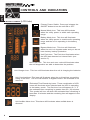
MCP-E Series
User's Manual
English
TABLE OF CONTENTS
MCP-E Series
User's Manual
1.
Introduction
2
2.
Controls and Indicators
4
3.
Installation
6
4.
Operation
13
5.
Troubleshooting
17
6.
Replacing the Battery
20
7.
Obtaining Service
24
8.
Specifications
25
9.
Configurable Parameters & Settings
26
10.
Limited Product Warranty
28
11.
Declaration of Conformity
29
© Copyright Para Systems, Inc., 2001
1
INTRODUCTION
English
Thank you for purchasing a MINUTEMAN™ power protection product. It has been
designed and manufactured to provide many years of trouble free service.
IMPORTANT SAFETY INSTRUCTIONS
SAVE THESE INSTRUCTIONS !
Please read the manual before installing your UPS. It provides the information that should
be followed during installation and maintenance of the UPS and the batteries allowing you
to correctly set up your system for the maximum safety and performance. Included is
information on customer support and factory service if it is required. If you experience a
problem with the UPS please refer to the Troubleshooting guide in this manual to correct
the problem or collect enough information so that the MINUTEMAN Technical Support
Department can rapidly assist you.
This symbolt
This symbol indicates "ATTENTION"
This symbol indicates "Risk of Electrical Shock"
NOTICE:
This equipment has been tested and found to comply with the limits
for a Class A computing device in accordance with the specifications in Subpart J
of Part 15 of FCC Rules and the Class B limits for radio noise emissions from digital
apparatus set out in the Radio Interference of the Canadian Department of
Communications. These limits are designed to provide reasonable protection against such
interference in a residential installation. This equipment generates and uses radio frequency
and if not installed and used properly, that is, in strict accordance with the manufacturer's
instructions, this equipment may cause interference to radio and television reception. If this
equipment does cause interference to radio or television reception, which can be determined
by turning the equipment off and on, the user is encouraged to try to correct the interference
by one or more of the following measures:
n Re-orient the receiving antenna
n Relocate the computer with respect to the receiver
n Move the computer away from the receiver
n Plug the computer into a different outlet so that the computer and receiver are on
different branch circuits.
n Shielded communications interface cables must be used with this product
WARNING:
Changes or modifications to this unit not expressly approved by the
party responsible for compliance could void the user's authority to operate the
equipment.
Receiving Inspection
After removing your MINUTEMAN UPS from it's carton, it should be inspected for damage
that may have occurred in shipping. Immediately notify the carrier and place of purchase if
any damage is found. Warranty claims for damage caused by the carrier will not be
honored.
2
WARNING: Risk of electrical shock. Hazardous live parts inside
this power supply are energized from the battery even when the AC
input power is disconnected.
To de-energize the outputs of the UPS:
1. If the UPS is on press the on/off button for 1 second
2. Disconnect the UPS from the AC power outlet
3. To deenergize the UPS completely, disconnect the battery.
This uninterruptible power source contains potentially hazardous voltages. DO
NOT attempt to disassemble the unit. This UPS contains no user serviceable
parts. Repairs and battery replacement must be performed by AUTHORIZED
SERVICE PERSONNEL ONLY.
CAUTION! To reduce the risk of electrical shock in conditions where load
equipment grounding cannot be verified, disconnect the UPS from the AC power
outlet before installing a computer interface cable. Reconnect the power cord
only after all signaling connections are made.
CAUTION! Connect the UPS to a two pole, three wire grounding AC
power outlet. The receptacle must be connected to appropriate branch protection
(circuit breaker or fuse). Connection to any other type of receptacle may result in
a shock hazard and violate local electrical codes
CAUTION! "High Leakage Current". The UPSs must be connected to the
appropiate building ground.
Para Systems Life Support Policy
As a general policy, Para Systems Inc. (Para Systems) does not recommend the use of any
of its products in life support applications where failure or malfunction of the Para Systems
product can be reasonably expected to cause failure of the life support device or to
significantly affect its safety or effectiveness. Para Systems does not recommend the use
of any of its products in direct patient care. Para Systems will not knowingly sell its
products for use in such applications unless it receives in writing assurances satisfactory
to Para Systems that (a) the risks of injury or damage have been minimized, (b) the
customer assumes all such risks, and (c) the liability of Para Systems Inc. is adequately
protected under the circumstances.
Examples of devices considered to be life support devices are neonatal oxygen analyzers,
nerve stimulators (whether used for anesthesia, pain relief, or other purposes), auto
transfusion devices, blood pumps, defibrillators, arrhythmia detectors and alarms, pacemakers, hemodialysis systems, peritoneal dialysis systems, neonatal ventilator incubators,
ventilators for both adults and infants, anesthesia ventilators, and infusion pumps as well as
any other devices designated as “critical” by the United States FDA.
Hospital grade wiring devices and leakage current may be ordered as options on many
PARA SYSTEMS UPS systems. PARA SYSTEMS does not claim that units with this
modification are certified or listed as Hospital Grade by PARA SYSTEMS or any other
organization. Therefore, these units do not meet the requirements for use in direct patient
care.
3
English
The packing materials that your UPS was shipped in, are carefully designed to minimize any
shipping damage. In the unlikely case that the UPS needs to be returned to MINUTEMAN,
please use the original packing material. Since MINUTEMAN is not responsible for shipping
damage incurred when the system is returned, the original packing material is inexpensive
insurance. PLEASE SAVE THE PACKING MATERIALS!
CONTROLS AND INDICATORS
English
FRONT PANEL (LCD Units)
Primary Power Switch: Press and release the
ON/OFF button to turn the unit ON or OFF.
Normal Mode Icon: This icon will illuminate
when the utility power is within safe operating
range.
Battery Mode Icon: This icon will illuminate
when the Utility power is outside safe operating
range and the unit is operating in the battery
mode.
Bypass Mode Icon: This icon will illuminate
when the unit is in bypass mode and you do not
have battery backup protection.
Unit Fault Icon: The Fault icon illuminates when
the UPS has detected an internal fault. (see
section 5)
Unit Fault Icon: This icon and error code will illuminate when
the self diagnostics are able to determine the problem.
Unit Charger Icon: This icon will illuminate when the unit is charging the batteries.
Unit Overload Icon: This icon will illuminate when the unit load has exceed the
rating of the UPS. The UPS will transfer to bypass mode if the overload is not
removed.
Estimated Time Remaining icons: These combination of LCD
icons will illuminate when selected and the UPS is operating
in the battery mode. The first time icon will appear as ">" if
the estimated time remaining is greater than ten (10) minutes.
This symbol will turn off when the estimated time remaining is
less than 10 minutes and the remaining time will appear in the
display.
Unit Audible Alarm Icon: This alarm will illuminate when audible alarm is
silenced.
4
Unit Output Icon: When selected, this will display the selected
item for the output from unit.
Unit Amperage Icon: When selected, this will display the amps
from either the input or output based on selection of input or
output as described previously.
Unit Voltage Icon: When selected, this will display the voltage
from either the input or output based on selection of input or
output as described previously.
Unit Frequency Icon: When selected, this will display the
frequency from either the input or output based on selection of
input or output as described previously.
Unit Load in Watts Icon: When selected, this will display the
load from either the input or output based on selection of input
or output as described previously.
!
Unit Battery Percentage Status Icon: When selected, this will
display the percentage of battery capability remaining.
Unit Load Percentage Status Icon: When selected, this will
display the percentage of load on the unit.
5
English
Unit Input Icon: When selected, this will display the selected
item for the input from utility.
INSTALLATION
English
INSTALLATION PLACEMENT
Install the UPS in a temperature controlled environment that is free of conductive contaminants. Select a location which will provide good air circulation for the UPS at all times.
Avoid locations near heating devices, water or excessive humidity, or where the UPS is
exposed to direct sunlight. Route power cords so they cannot be walked on or damaged.
Operating Temperature: 700VA-5000VA: 0 to 40°C, 7000VA: 0 to 32°C
Storage Temperature: -15 to +45°C
Operating Elevation: 0 to 3,000 Meters
Storage Elevation: 0 to 15,000 Meters
Operating and Storage Relative Humdity: 95%,
non-condensing
REAR PANEL (120Vac models shown)
Tower Models
1. Smart slot for optional cards
2. Switch, momentary switch used to
change displays or silence alarm
3. Dip switches used to configure unit
parameters
4. Simple Communications port (AS400)
5. RS232 intelligent communications port
6. Network protection (lan only)
7. External battery connection point
8. Output load receptacles
9. Output load circuit breakers
10. Incoming utility power cord
11. Incoming utility circuit breaker
6
Rackmount Models
1. Incoming utility power cord
2. Incoming utility circuit breaker
3. External battery connection point
4. Network protection (lan only)
5. Smart slot for optional cards
6. Switch, momentary switch used to change
displays or silence alarm
7. Dip switches used to configure unit
parameters
8. Simple Communications port (AS400)
9. RS232 intelligent communications port
10. Output load circuit breakers
11. Output load receptacles
English
1
2
3
4
7
8
5
6
9
10
MCP 5000iE and MCP 7000iE
1. Fans: Internal Cooling Fans.
2. Maintenance Bypass Switch: In normal operation the switch must be in the UPS position.
When doing routine maintenance the switch must be in the BPS position.
3. Output Circuit Breakers: Turn OFF/ON the output of the UPS.
4. Alarm Silencer: Silences the Alarm in the Battery Mode.
5. Configuration Switches: Must be set before turning the UPS ON (see page 8).
6. Input Circuit Breakers: Turn OFF/ON the input of the UPS.
7. RS232 Port: Intelligent Communications Port.
8. Contact Closure Port: Simple Communications Port (AS400).
9. External Battery Pack Connector: Remove the panel for external Battery Pack Connection.
10. Access Panel for Input/Output Terminals: Remove the panel for Input/Ouptut Connections.
7
INSTALLATION
(Must be performed by Authorized Service Personnel ONLY)
English
Be sure to read the installation placement and all the cautions before installing the UPS. The
MCP-E series UPS has external Battery Pack capability, please observe the following
warning when connecting the Battery Pack(s). WARNING! DO NOT PLUG THE BATTERY
PACK'S CONNECTOR INTO THE UPS's BATTERY CONNECTOR WHILE THE UPS IS TURNED
ON. NOTE: The red connectors/wires are the battery positive(+) and the black connectors/
wires are the battery negative(-) on all MINUTEMAN configurations.
MCP 5000iE and MCP 7000iE Input/Output/Battery Pack Connections
(Must be performed by Authorized Service Personnel ONLY)
Installation instructions for hardwiring the Input/Output Connections:
1. Crimp M6 ring terminals (part number R14-6 or equivalent) to the appropriate size input
and output cables (see page 9) using the appropiate Crimp tool (part number Crimpers RYO14 or equivalent).
Ring Terminal:
Size: M6 (or equivalent)
Part Number: R14-6 (or equivalent)
Manufacturer: Kai Suh Suh Enterprise Company., LTD (or equivalent)
Crimp tool:
Part number: Crimpers RYO-14 (or equivalent)
Manufacturer: Kai Suh Suh Enterprise Company., LTD (or equivalent)
2. Remove the access panel on the rear panel of the UPS.
3. Install the appropriate size strain relief into the input and output access holes.
4. Push the input cable through the strain relief nearest the input terminal block.
5. Connect L1 to the AC Input's "L" terminal, connect L2 to theAC Input's "N" terminal,
connect AC ground to the AC Input's ground terminal. Be sure that all the connections and
the strain relief are tightly secured.
6. Push the output cable through the strain relief nearest the output terminal block.
7. Connect L1 to the AC Output's "L" terminal, connect L2 to the AC Output's "N" terminal,
connect AC ground to the AC Output's ground terminal. Be sure that all the connections and
the strain relief are tightly secured.
8. Reinstall the access panel on the rear panel of the UPS.
9. Now the UPS is ready for the normal start-up procedure.
8
NOTE: The MCP 5000iE and 7000iE's AC input must be connected to an AC circut breaker
which will provide for an emergency power off. (Must be performed by Authorized
English
Service Personnel ONLY)
Model
MCP 5000iE
MCP7000iE
Input Circuit Breaker
40 Amp
50 Amp
Input Wire Size/Temp
8 AWG/min75°C 6 AWG/min75°C
Wire Conductor
Three conductor, copper wire only
Tightening torque for
Torque 17.6Lbs (8kg)
pressure wire connectors
having screws
Block diagram of the MCP 5000iE and MCP 7000iE input and output wiring.
9
Installation of the mounting tray and the stablizing feet.
(Must be performed by Authorized Service Personnel ONLY)
English
The MCP 5000iE and the MCP 7000iE must be installed into a stationary position due to the
hardwiring of the input and the output.
1. Move the UPS into the desired location.
2. Lay the mounting tray on the floor next to the UPS as shown below.
3. Roll the UPS onto the mounting tray.
4. Align the four screw holes on the mounting tray with the four screw holes on the bracket
at the front and rear of the UPS.
5. Install the four mounting tray retaining screws.
6. Install the four stablizing feet as shown below, two at the front and two at the rear.
7. Install the eight stablizing feet retaining screws as shown below.
8. The UPS is now ready for hardwiring the input and the output (See page 8).
10
The Rackmount Configuration comes with mounting brackets for the standard 19"
(46.5cm) rack. The mounting brackets to fit a 23" (59.2cm) standard rack are also
available. The screws for mounting the UPS to the rack are not included (screw size
varies with rack size). The kit includes, two mounting brackets and four retaining screws.
Locate the mounting bracket screw holes on the side panels of the UPS, at the front of the
UPS. Align the mounting bracket with the mounting bracket screw holes. Attach the
mounting bracket with the retaining screws. WARNING: Use two or more people when
installing the UPS into the rack. Use caution, the UPS is extremely heavy. Do not move the
rack after the units have been installed. The rack may be unstable due to the weight
distribution. Now the UPS is ready for the normal start-up procedure.
11
English
The MCP-E Series UPS can be installed in two different configurations.
The Tower Model allows the user to install the UPS next to the tower computer. Use
CAUTION, the UPS is extremely heavy. Place the UPS in the final desired location and
complete the rest of the installation procedure. Now the UPS is ready for the normal start-up
procedure.
CONNECTING TO AN AC SOURCE
English
Plug the UPS into a two pole, three wire, grounded receptacle only. Do not use extension
cords, adapter plugs, power strips or surge strips. The MCP 5000iE and MCP 7000iE must
be hardwired (see page 8).
COMPUTER INTERFACE CONNECTION (OPTIONAL)
MINUTEMAN Power Management software and interface cables kits can be used with the
MCP-E units. Use only MINUTEMAN or MINUTEMAN approved interface cables with these
UPS’s. Connect the interface cable to the 9 pin computer interface port on the rear of the
UPS. Secure the connector to the UPS via the screws on the connector housing. Connect
the other end of the cable to the device that will be monitoring/controlling the UPS.
NOTE: Connecting to the computer interface port is optional. The UPS works
properly without this connection.
NETWORK SURGE PROTECTION CONNECTION (OPTIONAL)
Connect a 10 Base-T network line to the protection sockets on the rear of the UPS (not
available on all models). This connection will require another length of network cable. The
cable coming from the networked system is connected to the port marked “IN”. The “OUT
port is connected to the equipment to be protected.
NOTE: Connecting to the Network Surge Protection connection is optional. The
UPS works properly without this connection.
CONNECTING YOUR EQUIPMENT
Plug the equipment into the output receptacles on the back panel of the unit. Do not use
extension cords, adapter plugs, power strips or surge strips. The MCP 5000iE and the MCP
7000iE are hardwire output connections only, be sure the output breaker is in the ON
position. Insure that you do not exceed the maximum output rating of the UPS (refer to the
UPS's back panel or the Electrical Specifications in this manual).
CAUTION!
DO NOT CONNECT A LASER PRINTER TO THE BATTERY BACKUP
RECEPTACLES ON THE UPS UNLESS THE UPS IS RATED 2000VA OR
GREATER. A LASER PRINTER DRAWS SIGNIFICANTLY MORE POWER
WHEN PRINTING THAN AT IDLE, AND MAY OVERLOAD THE UPS.
MAINTENANCE BYPASS SWITCH
(Must be performed by Authorized Service Personnel ONLY)
The 5000/7000VA units have a Maintenance Bypass Switch on the rear panel. The
maintenance bypass switch is used to tranfer the utility AC power to the output load without
interrupting the protected equipment, so that general maintenance can be performed. Follow
the steps below to transfer the UPS to the Maintenance Bypass Mode:
1. Turn the Maintenance Bypass Switch to "BPS".
2. Push the ON/OFF button on the front panel.
3. Wait for approximately five minutes before performing any maintenance.
4. The UPS is now ready for general maintenance.
Follow the steps below to switch the UPS back to the Normal On-Line Mode:
1. Push the ON/OFF button on the front panel.
2. Wait for approximately one minute for the inverter to start.
3. Turn the Maintenance Bypass Switch to "UPS".
4. The UPS is now operating in the Normal On-Line Mode.
12
English
OPERATION
TURNING THE UNIT ON/OFF
The UPS is shipped with the unit disabled. Turn dip switch #1 to the ON position before
attempting to turn on the unit. This will enable the unit. Set all of the dipswitches per the
desired setting for your environment prior to turning on the unit.
Turning ON/OFF the 700/1000VA
To turn ON the 700/1000VA. Plug the input power cord into the AC wall outlet. Push and
hold the ON/OFF button (on the front panel) for one beep, then release the button.
To turn OFF the 700/1000VA. Push and hold the ON/OFF button (on the front panel) for one
beep, then release the button. Unplug the input power cord from the AC wall outlet.
Turning ON/OFF the 2000/3000VA
To turn ON the 2000/3000VA. Plug the input power cord into the AC wall outlet. Put the
input circuit breaker (on the rear panel) in the ON position. Push the ON/OFF button on the
front panel.
To turn OFF the 2000/3000VA. Push the ON/OFF button on the front panel. Put the input
circuit breaker (on the rear panel) in the OFF position. Unplug the input power cord from the
AC wall outlet.
Turning ON/OFF the 5000/7000VA
To turn ON the 5000/7000VA. Hardwire the input and the output (see page 8). Put the
circuit breaker at the wall breaker panel to the ON position. Put the input circuit breaker (on
the rear panel) in the ON position. Push the ON/OFF button on the front panel. Put the output
circuit breaker (on the rear panel) in the ON position.
To turn OFF the 5000/7000VA. Put the output circuit breaker (on the rear panel) in the OFF
position. Push the ON/OFF button on the front panel. Put the input circuit breaker (on the
rear panel) in the OFF position. Put the circuit breaker at the wall breaker panel to the OFF
position.
NOTE: Do not turn the UPS OFF and then ON again very rapidly. Once the UPS has been
turned OFF, wait for approximately two minutes before turning the UPS ON again.
Configuration Switches for the MCP 700/1000. The "System Enable" switch must be
enabled for the UPS to operate.
13
English
MCP 2000 and MCP 3000. RS232 Port, Control Port pinouts and Confirguation Switches.
Configuration Switches for the MCP 2000/3000/5000/7000. The "System Enable" switch
must be enabled for the UPS to operate.
14
Place your unit in the desired location for use. Connect all equipment power cords to the
receptacles on the rear of the UPS. Please insure you confirm total power requirements
and do not overload the units.
English
Press and release the main power switch on the front of the unit to turn
on the unit. Press and release again to turn off the unit. Some models
have a circuit breaker on the rear panel that must be turned ON first and
then press the front panel switch to turn the unit ON.
English
The unit will turn on, perform a self diagnostic test, switch to bypass
mode and then turn on to full inverter mode automatically.
ALARMS
ON BATTERY
When the UPS is operating in the battery mode, the Battery Mode Icon will illuminate and the
audible alarm will sound every 10 seconds. The alarm will stop and the Battery Mode Icon
will extinquish once the UPS returns to AC normal operation.
UPS FAULT
When the UPS detects a fault, the Unit Fault Icon will illuminate and the UPS will emit a
sustained tone. The unit will also display a failure code if available. (see section 5 Troubleshooting for failure code definition)
OVERLOAD
When the amount of load attached to the UPS exceeds its power rating, the Unit Overload
Icon will illuminate and the UPS will emit a sustained tone. This alarm will remain on until the
excess load is removed or the UPS’s self protection circuit takes control. If the unit self
protection circuit takes control, the unit will switch to bypass mode until the overload is
removed. If the load is excessive, the input circuit breaker will open and the unit will shut
down.
REPLACE BATTERY
The UPS automatically tests the battery’s condition and will illuminate the Unit Battery Icon
and emit a short beep. This tone will be repeated every hour until the batteries passes a
self test. It is recommended that the UPS be allowed to charge overnight before performing
a battery test to confirm a Weak/Bad Battery condition.
LOW BATTERY WARNING
The UPS will emit two consecutive beeps every five seconds when the battery reserve
runs low. This continues until AC returns or the UPS shuts down from battery exhaustion.
COMMUNICATIONS PORT
Communications port information for 700VA and 1000VA units only:
The communications port is a standard DB9 female with both RS232 and relay contact
closure capability. The units will poll the port and activate the port for RS232 or contact
closure in accordance with the type of cable it finds connected to the port. To change the
port configuration requires the unit be turned off and restarted with the desired cable
connected. The pinout for the port is depicted per the chart below.
Pin 1:
Pin 2:
Pin 3:
Pin 4:
Pin 5:
Pin 6:
Pin 7:
Pin 8:
Pin 9:
Instant off ( pull and hold this pin low to turn off output receptacles)
/TXD
/RXD and receive ups shutdown command
AC fail, NO closes on event
Ground
Low battery warning, NO closes on event
Common return for all relays
Summary alarm, NO closes on AC fail, low battery warning, overload, UPS failure
or unit on bypass
Not Used
15
Communications port information for 2KVA, 3KVA, 5KVA and 7KVA units only:
English
These units contain two independent communications ports. Port one is for standard RS232
communications and labeled RS-232 Port. The second port is relay contact closure
configured for standard AS 400 ports. This port is labeled Control Port.
The pinout for the RS-232 port is depicted per the chart below. Note: when using the SNMP
option card, this port will be disconnected. Both the slot and the port may not be used at the
same time.
Communication settings: When using the RS232 port, the following settings should be used.
Baud Rate: 2400
Data Bits: 8
Stop Bits: None
Parity: 1
Pin 1:
Pin 2:
Pin 3:
Pin 4:
Pin 5:
Pin 6:
Pin 7:
Pin 8:
Pin 9:
Not Used
/TXD Transmit Data
/RXD Receive Data and Commands
Not Used
Ground
Not Used
Not Used
Not Used
Not Used
The pinout for the Control port is depicted per the chart below.
Pin 1:
Pin 2:
Pin 3:
Pin 4:
Pin 5:
Pin 6:
Pin 7:
Pin 8:
Pin 9:
UPS failure (fault)
Summary alarm (normally open, closes on event)
Common for pin 4
EPO or shutdown
Common ground for all relays.
Bypass active=make/ ups on=open
Battery low (normally open, closes on event)
UPS on=make/ bypass active=open
AC fail (normally open, closes on event)
Your UPS unit is shipped standard with SentryII monitoring software. This software may be
used for monitoring the UPS and power when loaded into your computer and connected via
the supplied software communication cable. This software is a detailed tool to help you
manage your power needs.
This software will also support a simpler style of controlled shutdown for the consumer that
is not interested in detail, but is still interested in a controlled unattended shutdown. The
simple software function requires the purchase and installation of a separate cable that is
not provided with the unit. Please contact your local vendor or Minuteman Technical support
department at 800-238-7272 or 972-446-7363 should you need to purchase this software
cable.
16
English
TROUBLESHOOTING
Symptom
WhatToDo
PossibleCause
E10 is displayed after Configuration dip switch is in
turning on unit
the off position
Turn Dip Switch #1 to on position
as defined on page 13
No AC utility power present
When turned on, the
unit operates in battery and unit Cold start function is
enabled
mode only
Check utility input power and
contact local service company if
required to correct utility problem
The unit switches from The fluctuation of the input utility Check the input utility condition.
normal to battery mode voltage or frequency is beyond Adjust Sync Range to 3Hz.
Contact loacal service personnel if
frequently
the preset guidelines
utility remains bad
The unit switches to
The unit may be overloaded
bypass mode
periodically by a random load
occasionally and then increase
switches back
Verify if the load may be affected
by a printer or excessive loading
such as numerous phones etc.
remove excessive load to eliminate
Diagnostic codes for 700VA and 1KVA
The 700VA and 1000VA units use LED displays to notify the User of an error detected by
the internal diagnostics system. The letter "E" is assumed and is not displayed on the LED
graph. The top row of LED's indicate the first number of the "diagnostic error" code. As an
example: if the third LED is illuminated, the first character of the "diagnostic error" code is 3.
The second row of LED's indicates the second number in the diagnostic error code. As an
example: if the second LED is illuminated, the second character of the "diagnostic error"
code is 2. These examples would provide an diagnostic error message of E32 with the "E"
assumed for all error codes. A sample of E32 is shown below for your reference.
LOAD
BATTERY
"EXAMPLE OF DIAGNOSTIC ERROR CODE E32"
17
If your unit should have a problem, please call our Technical Support department to resolve
any issues. Please call, 800-238-7272 or 972-446-7363 and ask for Technical Support.
When you call with a problem, please be prepared to provide the following information to the
technician.
English
Model number: example: MCP 3000 E
Model Part number: example: 900xxxxx (8-15 characters-always starts with 900)
Model Serial number: example: FC87011200001 (13 characters)
Length in Service: example 25 months
Diagnostic code at time of problem: example: E32
Time of day during failure: example: 4:15 am
Weather conditions during failure: example: clear skies, no power problems.
OurTechnical Support department is open from 8am -5pm Central standard time USA Monday
- Friday. Please feel free to consult our Power Forum on our website for assistance at
www.minutemanups.com
Code
Definition
E01
System off resulting from Microprocessor checksum error.
E03
Battery voltage is below safe operating range (AC mode).
E04
Battery voltage has exceeded safe operating range (AC mode).
E05
Thermal sensor is dead or unit exceeds safe temperature.
E10
Configuration dip switch is in the off position.
E13
Input/Output voltage difference is out of 6V specification (AC tracking mode).
E22
+DC bus voltage is out of the range of +15% to -10%.
E23
-DC bus voltage is out of the range of +15% to -10%.
E24
Phase unlocks between input and output.
E32
Power is over 100% for 60 seconds.
E32
Power is over 125% for 10 seconds.
E32
Power is over 150%.
E32
Power is over 300%
E32
RMS current is over 100% for 60 seconds.
E32
RMS current is over 125% for 10 seconds.
E32
RMS current is over 150% for 3 seconds
E32
RMS current is over 300%
E32
Power is over 100% or RMS current is over 100% for 5 seconds (DC mode).
E32
Power is over 125% (DC mode).
E40
Temperature is out of range.
E52
Output senses a short circuit.
E53
Battery test error (battery may be bad or needs charge time).
E55
Input voltage is over 150Vrms for 120vac units.
Diagnostic codes not listed are used by Engineering staff for programming purposes.
18
Diagnostic Error Codes for 2KVA, 3KVA, 5KVA, 7KVA units
Description
E00
System ROM checksum error.
E01
System RAM data read/write error.
E02
System EEPROM data read/write error.
E03
Communication fail between CPU & DSP
E05
Temperature over 100oC.
E07
Battery voltage is over specification (AC mode).
E08
Input voltage fail (Outside of safe operating range & cold start disable).
E10
Configure SW1 is set position “OFF”.
E11
AC Mode input out of range during normal startup.
E12
Battery voltage out of range during cold start.
E14
DC bus voltage out of range during cold start.
E15
Output/input voltage difference out of 3.125% (AC tracking mode).
E16
Output/setting voltage difference out of 3.125% (DC mode).
E17
Input frequency fail (Out of 45 ~ 65 Hz) & cold start disable.
E22
DC bus voltage out of range -85% or +12%
E23
Difference between DC bus is more then 70Vdc.
E25
Input / Output frequency difference out of 1Hz during AC mode normal
E26
Battery voltage low (2K-57V, 3K-76V, 5K-190V, 7K-228V) out of range (DC mode)
E32
RMS current over 100%
E33
Voltage difference more than 10% between setting and output
E40
Temperature over 80oC.
E42
Thermal sensor dead.
E53
Battery test error.(battery may be bad)
E54
Line-Neutral connection error.
E60
Transfer fail during AC Bypass to AC Mode
E63
Transfer fail during Battery Mode to normal AC mode.
E67
DC bypass to Battery mode time out in soft start.
E68
AC bypass to Normal mode time out in soft start.
E69
In/out Sync lasts too long.
E78
DIP Switch setting error(output voltage setting).
E80
DSP initial state data transfer error (clear 0ffh).
E81
No response when send data to DSP.
E82
DSP initial state data transfer error (55,aa,version).
E83
Data lost (every cycle received data less than 20 and more than 60 times).
E84
Input voltage break at bypass mode.
English
Error
19
REPLACING THE BATTERY
English
REPLACING THE BATTERY
(Must be performed by Authorized Service Personnel ONLY)
The Tower Series UPS has a replacable battery(s), however the unit must be turned off,
disconnected from utility and discharged prior to changing the batteries. The Rack Mount
Series UPS has a hot swappable battery kit. Please read the following warning statements
before attempting to service the battery(s).
NOTE: If there is a power interruption while replacing the hot-swappable batteries, with
the UPS on, the load will not be backed up.
WARNING!
This Uninterruptible Power Source contains potentially hazardous voltages.
Do not attempt to disassemble the unit. This UPS contains no user
serviceable parts. Repairs and Battery replacement must be performed by
Authorized Service Personnel ONLY.
not open or multlate batteries.
CAUTION: Do
skin and eyes and may be toxic.
Released electrolyte is harmful to the
CAUTION: Do not dispose of batteries in a fire.
WARNING!:
The batteries in this UPS are recyclable. Dispose of the batteries properly.
The batteries contain lead and pose a hazard to the environment and
human health if not disposed of properly. Refer to local codes for proper
disposal requirements or return the battery to Minuteman.
MCP-E SERIES Battery
Model #
Quantity
20
The batteries May explode.
Battery
Type
MCP 700(i) E
3 each
12V7.2AH
MCP 1000(i) E
3 each
12V7.2AH
MCP 2000(i) E
6 each
12V7.2AH
MCP 3000(i) E
8 each
12V7.2AH
MCP 5000i E
20 each
12V7.2AH
MCP 7000i E
24 each
12V7.2AH
A battery can present a
risk of electrical shock and high short circuit current. The following
precautions should be observed when working on batteries:
1. Remove watches, rings, or other metal objects.
2. Use hand tools with insulated handles.
3. Wear rubber gloves and boots.
4. Do not lay tools or other metal parts on top of batteries.
5. Disconnect charging source prior to connecting or disconnecting battery
terminals.
6. Determine if the battery is inadvertently grounded. If inadvertently
grounded, remove source of the ground. Contact with any part of a
grounded battery can result in electrical shock. The likelihood of such
shock will be reduced if such grounds are removed during installation
and maintenance.
CAUTION:
Replace batteries with the same number and type as originally installed in
the UPS. These batteries have pressure operated vents. When replacing
the batteries, replace with the same number:
Manufacturer
CSB
YUSA
PANASONIC
HITACHI
Model Number
GP/FR 12070 F2
NP7-12\250
LCR 12V 7.2S1
HV7-12 F2
These batteries are used in both the UPS and external Battery Packs.
21
English
English
CAUTION: System voltages range from 24 VDC to 288 VDC.
Battery Replacement Procedure for Tower Model
(Must be performed by Authorized Service Personnel ONLY)
English
PLEASE READ THE CAUTIONS BEFORE ATTEMPTING TO REPLACE THE BATTERIES
These units are not hot-swappable. Hot-swappable batteries means that the batteries can
be replaced without powering down the whole UPS system.
1. Turn off the equipment that is plugged into the output receptacles of the UPS.
2. Turn off the UPS using the primary power switch on the front.
3. Turn off the AC circuit breaker on the rear panel of the UPS (if applicable).
4. Unplug the UPS's AC power cord from the AC outlet.
5. Unplug the equipment from the output receptacles of the UPS.
6. Remove the cover of the UPS.
7. Disconnect the battery positive (red) wire and the all of the battery jumper wires.
8. Disconnect the battery negative (black) wire.
9. Remove the top four retaining screws and the top battery retaining bracket.
Step 7
Step 9
Step 8
10. Remove the top row of the batteries.
11. Remove the bottom four retaining screws and the bottom battery retaining bracket.
12. Remove the bottom row of the batteries.
13. Install the bottom row of new batteries.
14. Reinstall the bottom battery retaining bracket and the retaining screws.
15. Install the top row of new batteries.
16. Reinstall the top battery retaining bracket and the retaining screws.
17. Reconnect the battery negative (black) wire and the battery jumper wires. Verify proper
polarity, negative (black) wire to the battery negative terminal and the battery jumper wires
are connected properly.
18. Reconnect the battery positive (red) wire to the battery positive terminal. Some
sparking may occur, this is normal.
19. Reinstall the cover on the UPS.
20. Dispose of the batteries properly at an appropriate recycling facility or return them to the
supplier in the packing material for the new batteries. Follow local EPA guidelines when
disposing of batteries. Note: These batteries contain lead and must be disposed of per
environmental guidelines.
21. The UPS is now ready for the normal start-up procedure.
22
Battery Replacement Procedure for Rack Mount Models
PLEASE READ THE CAUTIONS BEFORE ATTEMPTING TO REPLACE THE BATTERIES
These units are hot-swappable. Hot-swappable batteries means that the batteries can be
replaced without powering down the whole UPS system. NOTE: If there is a power
interruption while replacing the hot-swappable batteries, with the UPS on, the load will not
be backed up.
1. Utitlize steps 1-5 from page 22 if you do not want to hot-swap. Then proceed.
2. Remove the three retaining screws from front panel of the UPS.
3. Remove the six retaining screws and the battery case retaining bracket.
4. Disconnect the battery wiring harness connector.
5. Remove the battery case.
6. Insert the new battery case.
7.Connect the battery harness connnector.
8. Reinstall the battery case retaining bracket and the retaining screws.
9. Reinstall the front panel and the retaining screws.
10. Dispose of the batteries properly at an appropriate recycling facility or return them to the
supplier in the packing material for the new batteries. Follow local EPA guidelines when
disposing of batteries. Note: These batteries contain lead and must be disposed of per
environmental guidelines.
11. The UPS is now ready for the normal start-up procedure if required.
23
English
(Must be performed by Authorized Service Personnel ONLY)
OBTAINING SERVICE
English
IF THE UPS REQUIRES SERVICE
1.Use the TROUBLESHOOTING section to eliminate obvious causes.
2.Verify there are no circuit breakers tripped. A tripped circuit breaker is the most common
problem.
3.Call your dealer for assistance. If you cannot reach your dealer, or if they cannot resolve
the problem call or fax MINUTEMAN Technical Support at the following numbers; Voice phone
(972) 446-7363 or 800-238-7272, FAX line (972) 446-9011 or visit our Web site at
www.minutemanups.com the "Discussion Board". Please have the following information
available BEFORE calling the Technical Support Department.
A. Your Name and address.
B. Where and when the unit was purchased.
C. Model number: example: MCP 3000 E
D. Model Part number: example: 900xxxxx (8-15 characters-always starts with 900)
E. Model Serial number: example: FC87011200001 (13 characters)
F. Length in Service: example 25 months
G. Diagnostic code at time of problem: example: E32
H. Time of day during failure: example: 4:15 am
I. Weather conditions during failure: example: clear skies, no power problems.
J. A description of the protected equipment, including model numbers if possible.
K. A technician will ask you for the above information and if possible, help solve your
problem over the phone. In the event that the unit requires factory service, the
technician will issue you a Return Material Authorization Number (RMA #).
L. If the UPS is under warranty, the repairs will be done at no charge. If not, there will be
a charge for repair.
4. Pack the UPS in its original packaging. If the original packaging is no longer available, ask
the Technical Support Technician to send a new set. It is important to properly pack the UPS
to avoid damage in transit. Never use Styrofoam (popcorn) beads for a packing material.
A. Include a letter with your name, address, day time phone number, RMA number, a
copy of your original sales receipt and a brief description of the problem.
5. Mark the RMA # on the outside of all packages. The shipping department cannot accept
any package without the RMA # marked on the outside.
6. Return the UPS by insured, prepaid carrier to:
MINUTEMAN UPS
Para Systems Inc.
1455 LeMay Drive
Carrollton, Tx. 75007
ATTN: Rma # _______
24
NOTE: 230Vac Specs Shown In ( )
Topology
Case Type
Agency Approvals
MCP 700 E MCP 1000 E MCP 2000 E
Realized Power Output Limit
Frequency Range
Output (Non-Battery Operation)
Output voltage
Frequency
Surge energy rating (one time, 10/1000 us waveform)
Output (Battery Operation)
Voltage
Voltage Regulation
Frequency
80-138 vac (160-274)
700VA
1000VA
500W
Rack Mount unit w/ one external battery
Rack Mount unit w/ two external battery
Rack Mount unit w/ three external battery
Rack Mount unit w/ four external battery
Rack Mount unit w/ five external battery
84-138 vac (160-274)
2000VA
3000VA
170-274 vac
7000VA
5000VA
3500W
700W
2100W
1400W
45 to 65 auto frequency (user defined for start on battery)
100,110,115,120 vac (220,230,240 vac)
50 / 60 Hz +/-5 Hz.
450Joules
240Joules
4900W
220,230,240 only
310Joules
220,230,240
100,110,115,120 vac (220,230,240 vac)
+/- 2% until low battery warning
50 or 60 Hz +/- 1% unless syncronized to line
True Sine Wave
0 ms
Spill proof, maintenance free, sealed lead-acid
36VDC 7.2Ah
72VDC 7.2Ah 96VDC 7.2Ah
240VDC 7.2Ah
288VDC 7.2Ah
10 minutes full load, 28 minutes half load
7-9 full load, 18-25 half load
Yes, available on all models of both Tower and Rack Mount versions
Typical Full load/Half load Runtimes w/ optional Batteries
Tower unit w/ one external battery
33 / 85
54 / 137
Tower unit w/ two external battery
91 / 228
55 / 141
Tower unit w/ three external battery
Tower unit w/ four external battery
Tower unit w/ five external battery
MCP 7000 E
$40,000 Domestic USA, Canada and Alaska only
Waveform
Typical Transfer Time
Battery System
Battery Type
Battery system by unit
Typical battery runtimes (internal battery)
External Battery Packs available
MCP 5000 E
Tower Version Only
UL, cUL, TUV, CE, EMC, FCC class A
3 year
Warranty
Equipment Protection Policy
Input (Non-Battery Operation)
Voltage Range
Input Apparent Power Rating
MCP 3000 E
Double Conversion On-Line
Tower and Rack Mount Versions Available
155 / 366
200 / 471
266 / 625
54 / 137
101 / 233
130 / 299
91 / 228
155 / 366
200 / 471
55 / 141
101 / 233
130 / 299
175 / 396
266 / 625
175 / 396
33 / 85
44 / 115
101 / 237
159 / 367
220 / 505
271 / 650
33 / 86
72 / 169
111 / 257
152 / 350
186 / 447
38 / 99
87 / 209
138 / 323
191 / 541
245 / 581
29 / 74
62 / 149
97 / 226
132 / 305
168 / 399
50 / 132
41 / 102
84 / 223
145 / 349
85 / 213
120 / 277
168 / 390
206 / 490
N/A
283 / 487
248 / 613
N/A
N/A
N/A
N/A
N/A
N/A
N/A
N/A
N/A
Mechanical
Tower Model Dimensions net (L x W x H)
405 x 145 x 222mm
Tower Model Dimensions net (L x W x H)
15.94 x 5.71 x 8.74in
448 x 216 x 365mm
17.64 x8.5 x 14.37in
24.25 x 8.5 x 26.69in
Tower Shipping Dimensions (L x W x H)
Tower Shipping Dimensions (L x W x H)
516 x 266 x 343mm
20.31 x10.47 x 13.5in
573 x 333 x 510mm
22.6 x 13.1 x 20.1in
830 x 380 x 927mm
32.7 x 15 x 36.5in
Tower Net Weight Kg (lb)
15.3Kg 33.7lb
Tower Shipping Weight Kg (lb)
17.1Kg 38lb
Rack Mount Dimensions net (L x W x H)
438 x 425 x 88mm
Rack Mount Dimensions net (L x W x H)
17.24 x 16.73 x 3.46in
Rack Mount Shipping Dims (L x W x H)
547 x 547 x 225mm
Rack Mount Shipping Dims (L x W x H)
21.5 x 21.5 x 8.9in
Rack Mount Net Weight Kg (lb)
18.93Kg 41.7lb
Rack Mount Shipping Weight Kg (lb)
21.53Kg 48lb
Standard Input Plug Type
5-15P
4-5-15R
Standard Output Receptacle Type (220vac)
(IEC320)
33Kg 72.9lb 39.3Kg 86.6lb
35.9Kg 79lb 42.1Kg 93lb
510 x 425 x 177mm
20 x 16.73 x 6.97in
776 x 596 x 335mm
30.6 x 23.5 x 13.2in
39Kg 86lb 44.5Kg 98.1lb
44.4Kg 86lb 50.5Kg 112lb
5-20P
L5-30P
4-5-15/20R
(IEC320)
4-5-15R&1L5-30R (IEC320)
616 x 216 x 678mm
93Kg 205lb
106Kg 234lb
106Kg 234lb
118Kg 261lb
N/A
N/A
N/A
N/A
N/A
N/A
Hardwire Input and Output
Hardwire Input and Output
25
English
SPECIFICATIONS
English
CONFIGURABLE PARAMETERS
AND SETTINGS
(These items may require optional software or hardware)
FUNCTION
FACTORY DEFAULT
USER CHOICES
DESCRIPTION
UPS ID
MCP-E SERIES
Up to 64 characters to
define the UPS
Use this function to uniquely identify the
UPS in your network configuration
Battery installation date
Date of Manufacture
Date of Battery Replacementday/month/year (xx/xx/xxxx)
Enter the current date when
replacing the batteries
Battery life in days
Preset for 1826 days
Enter up to 5 characters
When replacing the batteries,
calculate the actual number of days in
use after manufacture date and then
enter this expected life for your
environment
Auto Restart:
Enable/Disable
Enabled
User may Enable or
Disable Autorestart
When "enabled", the UPS will
automatically restart and operate in
normal AC mode after a low battery
shutdown and normal AC has returned
Set audible
alarm state
Enabled
User may Enable or Disable
until Low Battery Warning
Enabled: The UPS will emit an
audible alarm every 10 seconds
when in the battery mode.
Disabled until Low Battery Warning:
Used when software is controlling the
UPS or to silence the alarm. In
this state, the UPS will not emit
an audible alarm until the unit
reaches low battery warning level.
Enable or Disable all
UPS functions
Disabled
User is required to enable prior
to operation. The UPS will not
operate until enabled.
This is a safety feature to prevent
operation while packaged during
shipping.
Set Inverter Output
Voltage
120 vac on 120 volt units.
230 vac on 230 volt units.
120 volt units: 100,110,115,120
230 volt units: 220,230,240
Allows the customer to set the voltage
based on the environment in which the
unit will be installed. This voltage is
set via external dip switch. The dip
switch is on the rear panel of the unit.
26
The MCP-E series UPS has a replacable receptacle panel. The receptacle panel can be
configured with multiple choices of receptacles. This will allow the user to customize the
output receptacles for their specific applications. MINUTEMAN will only use UL or CE
approved receptacles. To customize your MINUTEMAN UPS for your specific application,
contact your local distributor or contact MINUTEMAN at 972-446-7363, 800-238-7272 or
fax 972-446-9011 to find out which opitions are available. Come visit our web site at
www.minutemanups.com to find out about all the Power Protection products available
from MINUTEMAN.
The 700VA and 1000VA units may have the following optional panels:
One panel with two (2) duplex receptacles of any size.
One panel with one (1) twistlock receptacle of 20 or 30 amps.
The 2000VA and 3000VA units may have the following option panels:
One panel with one (1) duplex & one (1) twistlock receptacle of any size up to 30 amps.
MINUTEMAN reserves the right to make changes without notice.
Sample of Replacable and Configuarable
panel on 2000VA and 3000VA
27
English
Customized Output Receptacle Panels
LIMITED PRODUCT WARRANTY
English
LIMITED PRODUCT WARRANTY
Para Systems Inc. (Para Systems) warrants this equipment, when properly applied
and operated within specified conditions, against faulty materials or workmanship for a
period of three years from the date of purchase. For equipment sites within the United
States and Canada, this warranty covers repair or replacement of defective equipment at
the discretion of Para Systems. Repair will be from the nearest authorized service center.
Replacement parts and warranty labor will be borne by Para Systems. For equipment
located outside of the United States and Canada, Para Systems only covers faulty parts.
Para Systems products repaired or replaced pursuant to this warranty shall be warranted
for the unexpired portion of the warranty applying to the original product. This warranty
applies only to the original purchaser who must have properly registered the product within
10 days of purchase.
The warranty shall be void if (a) the equipment is damaged by the customer, is
improperly used, is subjected to an adverse operating environment, or is operated outside
the limits of its electrical specifications; (b) the equipment is repaired or modified by anyone
other than Para Systems or Para Systems-approved personnel; or (c) has been used in a
manner contrary to the product’s operating manual or other written instructions.
Any technical advice furnished before or after delivery in regard to use or application
of Para Systems’s equipment is furnished without charge and on the basis that it represents
Para Systems’s best judgment under the circumstances, but it is used at the recipient’s sole
risk.
EXCEPT AS PROVIDED HEREIN, PARA SYSTEMS MAKES NO WARRANTIES, EXPRESSED OR IMPLIED, INCLUDING WARRANTIES OF MERCHANTABILITY AND FITNESS FOR
A PARTICULAR PURPOSE. Some states do not permit limitation of implied warranties;
therefore, the aforesaid limitation(s) may not apply to the purchaser.
EXCEPT AS PROVIDED ABOVE, IN NO EVENT WILL PARA SYSTEMS BE LIABLE FOR
DIRECT, INDIRECT, SPECIAL, INCIDENTAL, OR CONSEQUENTIAL DAMAGES ARISING OUT OF
THE USE OF THIS PRODUCT, EVEN IF ADVISED OF THE POSSIBILITY OF SUCH DAMAGE.
Specifically, Para Systems is not liable for any costs, such as lost profits or revenue, loss of
equipment, loss of use of equipment, loss of software, loss of data, cost of substitutes,
claims by third parties, or otherwise. The sole and exclusive remedy for breach of any
warranty, expressed or implied, concerning Para Systems’s products and the only obligation
of Para Systems hereunder, shall be the repair or replacement of defective equipment,
components, or parts; or, at Para Systems’s option, refund of the purchase price or
substitution with an equivalent replacement product. This warranty gives you specific legal
rights and you may also have other rights which vary from state to state.
Longer term and F.O.B. job site warranties are available at extra cost. Contact Para
Systems (1-972-446-7363, 800-238-7272 or fax 972-446-7363) for details.
28
English
DECLARATION OF CONFORMITY
Application of Council Directive(s): 89/336/EEC, 7/23/EEC
Standard(s) to which Conformity is declared: EN50091-1, EN50091-2,
EN60555-2, EN61000-3
Manufacturer’s Name: Para Systems, Inc. (MINUTEMAN UPS)
Manufacturer’s Address:1455 LeMay Drive
Carrollton, Texas 75007 USA
Type of Equipment: Uninterruptible Power Supplies
Model No: MCP 700 E (Y), MCP 1000 E (Y), MCP 2000 E (Y), MCP 3000 E
(Y), MCP 5000 E (Y), MCP 7000 E (Y), MCP 700RM E (Y), MCP 1000RM E
(Y), MCP 2000RM E (Y), MCP3000RM E (Y)
Year of Manufacture: Beginning October 15, 2001
I, the undersigned, hereby declare that the equipment specified above
conforms to the above Directive(s).
Date: October 15, 2001
Robert Calhoun
(Signature)
Place: Carrollton, Tx. USA
Manager Engineering
(Title)
29
English
Notes:
30
32
Para Systems, Inc.
1455 Lemay Dr.
Carrollton, TX 75007
Phone: 972-446-7363
800-238-7272
Fax: 972-446-9011
Quickfax: 800-263-3933
Internet: minutemanups.com
PN:34000203 Rev 0