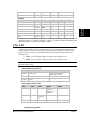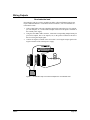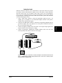
1
V Series Network Controllers User’s Guide Alcorn McBride February 25, 2014 Document Revision 2.1 February 25, 2014 Copyright 1996-2014 Alcorn McBride, Inc. All rights reserved. Every effort has been made to assure the accuracy of the information contained in this manual, and the reliability of the Alcorn McBride Show Control hardware and software. Errors can sometimes go undetected, however. If you find one, please bring it to our attention so that we can correct it for others. Alcorn McBride welcomes comments and suggestions on the content and layout of its documentation. Applications described herein are for illustrative purposes only. Alcorn McBride Inc. assumes no responsibility or liability for the use of these products, and makes no representation or warranty that the use of these products for specific applications will be suitable without further testing or modification. Alcorn McBride products are not intended for use in applications where a malfunction can reasonably be expected to result in personal injury. Customers using or selling Alcorn McBride products for use in such applications do so at their own risk, and agree to fully indemnify Alcorn McBride for any damages resulting from such improper use or sale. Alcorn McBride Inc. reserves the right to make changes to these products, without notice, in order to improve their design or performance. V16Pro™, V4Pro™, and VCore™ are trademarks of Alcorn McBride Inc., all rights reserved. Hardware Design: Firmware Design: Software Design: Documentation: Mechanical Design: Jim Carstensen, Scott Harkless, and Joy Burke Joy Burke, Scott Harkless and Adam Rosenberg Steve Alcorn, Joy Burke, and Adam Rosenberg John Conley, Joy Burke, Adam Rosenberg, Kevin Lang, Diego Reano, Jim Carstensen and Steve Alcorn Martin Chaney Alcorn McBride Inc. 3300 S. Hiawassee, Bldg. 105 Orlando, Florida 32835 TEL: (407) 296-5800 FAX: (407) 296-5801 http://www.alcorn.com [email protected] Table of Contents Page 2 Table of Contents Table of Contents ..................................................................................................................................... 3 Welcome ................................................................................................................................................ 11 Product Comparison Chart ................................................................................................................. 11 Important Information ........................................................................................................................ 12 Quick Start Guide ................................................................................................................................... 13 1. Open Example Script...................................................................................................................... 13 2. Connect.......................................................................................................................................... 13 3. Watch and Run! ............................................................................................................................. 13 WinScriptLive Tutorial ........................................................................................................................... 14 Opening WinScript Live and Creating a Script ................................................................................... 14 Configuring the Script ........................................................................................................................ 15 Working with Resources – Clicking and Drag & Drop ........................................................................ 16 Naming Resources ............................................................................................................................. 17 Buttons.......................................................................................................................................... 17 Variables ....................................................................................................................................... 18 Devices ......................................................................................................................................... 19 Writing The Script ............................................................................................................................. 21 Sequences ..................................................................................................................................... 21 Events ........................................................................................................................................... 22 Edit the Default Sequence .............................................................................................................. 23 Edit the MainShow Sequence ........................................................................................................ 25 Error Check and Send ........................................................................................................................ 33 Connecting Equipment ....................................................................................................................... 33 WinScript Live Resources ...................................................................................................................... 34 Sequences .......................................................................................................................................... 34 Sequence Columns ........................................................................................................................ 34 Sequence Clock ............................................................................................................................. 35 Events................................................................................................................................................ 36 Event Grid View ........................................................................................................................... 36 Event Timeline View ..................................................................................................................... 36 Variables ........................................................................................................................................... 37 User Variables ............................................................................................................................... 37 Device Variables ........................................................................................................................... 38 Devices .............................................................................................................................................. 38 Inputs ................................................................................................................................................ 41 IO64 Slave Inputs .......................................................................................................................... 41 Modbus TCP Slave Inputs ............................................................................................................. 42 Outputs .............................................................................................................................................. 44 IO64 Slave Outputs ....................................................................................................................... 44 Modbus TCP Slave Inputs ............................................................................................................. 45 Buttons .............................................................................................................................................. 48 Triggers ............................................................................................................................................. 48 Trigger Types ................................................................................................................................ 49 Trigger Cause ................................................................................................................................ 49 Timeline ................................................................................................................................................. 50 Display Timeline................................................................................................................................ 50 Play, Pause, Stop, and Execute ........................................................................................................... 50 Current Time Marker ......................................................................................................................... 51 Timeline Specific Functions ............................................................................................................... 51 View Time .................................................................................................................................... 51 New Event, New Sequence, Delete ................................................................................................ 52 Table of Contents Page 3 Display Options............................................................................................................................. 53 Groups .......................................................................................................................................... 54 Markers......................................................................................................................................... 56 Lock the Screen ............................................................................................................................. 56 Event Buttons ................................................................................................................................ 57 Other Functionalities ..................................................................................................................... 57 Properties Window............................................................................................................................. 57 WinScript Live Timecode (SMPTE/EBU) ............................................................................................... 59 Display the Timecode Configuration Dialog ....................................................................................... 59 Internal Timecode Settings ................................................................................................................. 60 Lock to External Video Sync ......................................................................................................... 60 External (SMPTE/EBU) Timecode Settings........................................................................................ 60 General Settings ............................................................................................................................ 60 Read Settings ................................................................................................................................ 61 Generate Settings........................................................................................................................... 61 WinScript Live "Live Mode" .................................................................................................................. 63 Sequence Status ................................................................................................................................. 63 Event Status ....................................................................................................................................... 63 Highlighted Events ........................................................................................................................ 63 Current Time ................................................................................................................................. 63 Watches ............................................................................................................................................. 64 Adding Watches ............................................................................................................................ 64 Viewing/Changing Value............................................................................................................... 64 Forces ........................................................................................................................................... 64 Live Log ............................................................................................................................................ 65 Live Display ...................................................................................................................................... 65 Live Config........................................................................................................................................ 65 Pinging Devices ............................................................................................................................ 65 Finding Devices ............................................................................................................................ 66 Setting Device Addresses .............................................................................................................. 67 Resetting IP Addresses – AMI/O ................................................................................................... 67 Show Controller External Control ........................................................................................................... 69 "ShowTouch" and "Touch" Software .................................................................................................. 69 Ami-Terminal Control........................................................................................................................ 69 Webpage Control ............................................................................................................................... 70 iPhone Control ................................................................................................................................... 70 1: Setup TCP Server on Show Controller ....................................................................................... 70 2: Add Incoming Message Triggers................................................................................................ 71 3: Control with iPhone App ........................................................................................................... 72 Terminal Control................................................................................................................................ 73 1: Setup TCP Server on Show Controller ....................................................................................... 73 2: Add Incoming Message Triggers................................................................................................ 74 3: Control with Putty or TCP Client ............................................................................................... 75 Redundant Mode ................................................................................................................................ 77 Redundant Mode Setup.................................................................................................................. 77 Redundant Mode in Touch............................................................................................................. 79 WinScript Live Command Reference ...................................................................................................... 81 Discrete Events .................................................................................................................................. 81 On ................................................................................................................................................. 81 Off ................................................................................................................................................ 81 Toggle........................................................................................................................................... 81 Blink ............................................................................................................................................. 82 Pulse ............................................................................................................................................. 82 Out Port ........................................................................................................................................ 83 In Port ........................................................................................................................................... 83 Logical Events ................................................................................................................................... 84 Table of Contents Page 4 On ................................................................................................................................................. 84 Off ................................................................................................................................................ 84 Toggle........................................................................................................................................... 84 Add ............................................................................................................................................... 85 Subtract ......................................................................................................................................... 85 Divide ........................................................................................................................................... 85 Multiply ........................................................................................................................................ 85 BitAnd .......................................................................................................................................... 86 BitOr ............................................................................................................................................. 86 Mod .............................................................................................................................................. 86 Concat........................................................................................................................................... 86 Format .......................................................................................................................................... 86 Set Variable = ............................................................................................................................... 87 Save Variable ................................................................................................................................ 88 Restore Variable ............................................................................................................................ 88 Program Control Events ..................................................................................................................... 89 Start .............................................................................................................................................. 90 Pause............................................................................................................................................. 90 Stop Loop ..................................................................................................................................... 90 Reset ............................................................................................................................................. 90 Goto .............................................................................................................................................. 90 If On, If Off................................................................................................................................... 91 If =, If not =, If >, If >=, If <, If <= ................................................................................................ 92 End If ............................................................................................................................................ 93 Else ............................................................................................................................................... 93 Nop ............................................................................................................................................... 94 Display Events ................................................................................................................................... 95 Display.......................................................................................................................................... 95 Store Display................................................................................................................................. 96 Recover Display ............................................................................................................................ 96 Timecode (LTC, SMPTE, EBU) and Internal Time Events ................................................................. 97 Delay ............................................................................................................................................ 97 Timecode Set ................................................................................................................................ 97 Timecode Pause ............................................................................................................................ 97 Timecode Start .............................................................................................................................. 98 Timecode Stop .............................................................................................................................. 98 Timecode Stop Loop ..................................................................................................................... 98 Get Seq Time ................................................................................................................................ 98 Arm .............................................................................................................................................. 98 Disarm .......................................................................................................................................... 99 Network Events ................................................................................................................................. 99 Send Mail ...................................................................................................................................... 99 Number Generation ............................................................................................................................ 99 Get Random .................................................................................................................................. 99 Device Control Events ..................................................................................................................... 100 Message Out ............................................................................................................................... 100 V16Pro................................................................................................................................................. 101 Specifications .................................................................................................................................. 101 Certifications ................................................................................................................................... 102 LTC Ports ........................................................................................................................................ 103 Serial Ports ...................................................................................................................................... 103 RS-232/422/485 Ports.................................................................................................................. 103 Ethernet Ports .................................................................................................................................. 104 Ethernet Cables ........................................................................................................................... 104 Programmer Ports ............................................................................................................................ 106 RS-232C ..................................................................................................................................... 106 Table of Contents Page 5 USB ............................................................................................................................................ 106 Ethernet Ports A and B ................................................................................................................ 106 Show Control Ports .......................................................................................................................... 107 Ports 1-16: RS-232 or RS-422/485............................................................................................... 107 MIDI Ports .................................................................................................................................. 107 Ethernet Ports A and B ................................................................................................................ 107 Display ............................................................................................................................................ 108 Menu Wheel .................................................................................................................................... 109 Menu Map................................................................................................................................... 109 Function Description ................................................................................................................... 111 System Sub-menu........................................................................................................................ 111 System ............................................................................................................................... 111 Real-Time Clock ................................................................................................................ 112 LTC/SMPTE ...................................................................................................................... 113 Network ............................................................................................................................. 113 Password ............................................................................................................................ 113 Script Configuration ........................................................................................................... 113 Digital Inputs ................................................................................................................................... 114 Input Connector........................................................................................................................... 114 Voltage Inputs vs. Contact Closures ............................................................................................. 115 Input Configuration ..................................................................................................................... 116 Input Wiring................................................................................................................................ 117 Connecting a Voltage Input ..................................................................................................... 117 Connecting a Contact Closure ...................................................................................................... 118 Using Front Panel Buttons ........................................................................................................... 119 Digital Outputs ................................................................................................................................ 120 Configuring Outputs .................................................................................................................... 120 Output Connector ........................................................................................................................ 120 Wiring Outputs............................................................................................................................ 122 Non-inductive load ................................................................................................................. 122 Inductive loads........................................................................................................................ 123 Video Sync Input ............................................................................................................................. 124 SMPTE Reader/Generator ................................................................................................................ 124 Power Supply................................................................................................................................... 124 Rear DIP Switches ........................................................................................................................... 125 Firmware ......................................................................................................................................... 126 Show Memory ................................................................................................................................. 126 V16+ or V4+ Compatibility ............................................................................................................. 127 Hardware Compatibility .............................................................................................................. 127 Importing .amw files (WinScript scripts)...................................................................................... 127 V4Pro................................................................................................................................................... 129 Specifications .................................................................................................................................. 129 Certifications ................................................................................................................................... 130 Serial, USB, Ethernet, Inputs and Outputs ........................................................................................ 131 VCore .................................................................................................................................................. 132 Specifications .................................................................................................................................. 134 Setting VCore IP Address ................................................................................................................ 135 DHCP (Automatic Assignment) ................................................................................................... 135 Manual IP Set .............................................................................................................................. 135 USB or Serial Set ........................................................................................................................ 136 Naming VCore................................................................................................................................. 136 Serial Port ........................................................................................................................................ 136 Ethernet Ports .................................................................................................................................. 137 USB................................................................................................................................................. 137 Digital Inputs ................................................................................................................................... 138 Input Connector........................................................................................................................... 138 Table of Contents Page 6 Input Configuration ..................................................................................................................... 138 Input Wiring................................................................................................................................ 139 Connecting a Voltage Input ..................................................................................................... 139 Connecting a Contact Closure ................................................................................................. 140 Digital Outputs ................................................................................................................................ 141 Configuring Outputs .................................................................................................................... 141 Output Connector ........................................................................................................................ 141 Wiring Outputs............................................................................................................................ 142 Non-inductive load ................................................................................................................. 142 Inductive loads........................................................................................................................ 143 LED Indicators ................................................................................................................................ 144 LEDs on Boot ............................................................................................................................. 144 Power Supply................................................................................................................................... 145 Power over Ethernet .................................................................................................................... 145 Rear DIP Switches ........................................................................................................................... 145 Show Memory ................................................................................................................................. 146 Ethernet Step by Step............................................................................................................................ 147 Hardware ......................................................................................................................................... 147 Network Equipment..................................................................................................................... 147 Hubs ........................................................................................................................................... 148 Switches ...................................................................................................................................... 148 Routers........................................................................................................................................ 148 Addresses and Routing ..................................................................................................................... 148 IP Addressing .............................................................................................................................. 149 Subnet Mask ............................................................................................................................... 149 Gateway ...................................................................................................................................... 149 Connecting the Hardware ................................................................................................................. 149 Network A (Point-to-Point) ......................................................................................................... 150 Network B (Multipoint Connections) ........................................................................................... 150 PC Configuration ............................................................................................................................. 150 Show Controller Configuration......................................................................................................... 153 Device Identification ........................................................................................................................ 153 Network A ID ............................................................................................................................. 153 Network B IDs ............................................................................................................................ 154 Setting Device IP Addresses ............................................................................................................. 155 Try It Out......................................................................................................................................... 156 Scheduler (Web-based) ......................................................................................................................... 157 Getting Started ................................................................................................................................. 157 Creating a New Schedule File .......................................................................................................... 157 Editing Schedule Entries .................................................................................................................. 159 WEB Server Quick Start ....................................................................................................................... 163 Step 1: Connecting to the Web Server .......................................................................................... 163 Step 2: Configuration................................................................................................................... 164 Step 3: Customer Web Page......................................................................................................... 164 Step 4: Understanding home.php.................................................................................................. 165 Hypertext Transfer Protocol ............................................................................................................. 166 File Names and Types ...................................................................................................................... 166 Show Controller Web-Script ............................................................................................................ 167 Web-Script Blocks ...................................................................................................................... 167 If Statements ............................................................................................................................... 167 Variables ..................................................................................................................................... 168 Functions .................................................................................................................................... 170 Function Params................................................................................................................. 173 Web Server Configuration ........................................................................................................... 174 Serial and Ethernet Control ................................................................................................................... 175 Command set ................................................................................................................................... 175 Table of Contents Page 7 ?V Get Firmware Version ...................................................................................................... 175 ?S Get SMPTE Firmware Version ......................................................................................... 175 ES Enable SMPTE ................................................................................................................. 176 DS Disable SMPTE ........................................................................................................... 176 PS Pause SMPTE (Next Loop Point)...................................................................................... 176 IS Pause SMPTE (Immediately) ....................................................................................... 177 CT Get/Set SMPTE Time ....................................................................................................... 177 ID Get/Set Unit ID ................................................................................................................ 177 IP Get/Set IP address ........................................................................................................ 178 SM Get/Set Subnet Mask number ....................................................................................... 178 GW Get/Set Gateway IP Address ........................................................................................ 178 DA Get/Set Date ................................................................................................................ 179 TI Get/Set Time................................................................................................................ 179 US Get/Set User Name ........................................................................................................... 180 PW Get/Set Password ......................................................................................................... 180 SD Get/Set DST Enable ......................................................................................................... 180 DT Get/Set DST Type ........................................................................................................ 181 TZ Get/Set Time Zone ........................................................................................................... 181 DI Display Text ..................................................................................................................... 181 LO Get/Set Longitude Coordinates ..................................................................................... 182 LA Get/Set Latitude Coordinates........................................................................................ 182 VA Get/Set a Variable ........................................................................................................ 182 VT Toggle a Boolean Variable ........................................................................................... 183 RJ Reset Sequence................................................................................................................. 183 PA Pause a Sequence ............................................................................................................. 183 SL Stop a Looping Sequence.................................................................................................. 183 PL Run a Sequence ................................................................................................................ 184 SQ Get Sequence Status ......................................................................................................... 184 OU Output Control ............................................................................................................. 184 SS Send Message................................................................................................................... 185 XX Reboot ......................................................................................................................... 185 NI Get/Set NTP IP Address ................................................................................................... 185 NE Enable/Disable the NTP Function ................................................................................. 186 NJ Get/Set the Ethernet Port for NTP ..................................................................................... 186 TS Time Stamp...................................................................................................................... 186 SF Get/Set Active Script file .................................................................................................. 187 NM Get/Set Device Name ................................................................................................... 187 FT Get Script Edit Date.......................................................................................................... 187 DH Enable/Disable the DHCP Function .............................................................................. 188 SJ Get/Set the Ethernet Port for SMTP .................................................................................. 188 SA Get/Set the SMTP Address ............................................................................................... 189 SP Get/Set the SMTP Port ..................................................................................................... 189 SU Get/Set the SMTP User Login Name................................................................................. 189 SW Get/Set the SMTP Password......................................................................................... 190 FR Get/Set the SMTP From Name ......................................................................................... 190 MA Send E-Mail................................................................................................................. 191 HJ Get/Set the HTTP Ethernet Port ........................................................................................ 191 HP Get/Set the HTTP WEB Page ........................................................................................... 192 RI Get/Set Redundant IP Address .......................................................................................... 192 RX Get/Set Redundant Ethernet Jack.................................................................................. 192 MS Get/Set Master Slave Message ..................................................................................... 193 TMS Get/Set Master Slave Timeout Period ........................................................................... 193 JP Jump to Timecode Message. ............................................................................................ 194 LV Live Mode ................................................................................................................... 194 EX Execute a command ..................................................................................................... 195 Product File Creator Tool ..................................................................................................................... 196 Table of Contents Page 8 Getting Started ................................................................................................................................. 196 Adding Events ................................................................................................................................. 197 Creating/Editing Your Own Product File via XML ................................................................................ 200 Protocol File Storage........................................................................................................................ 200 Getting Started ................................................................................................................................. 200 Product Section ................................................................................................................................ 201 Hardware Section ............................................................................................................................. 201 Protocol Section ............................................................................................................................... 201 Commands Section .......................................................................................................................... 202 Command Parameters .................................................................................................................. 203 Parameter Rules .......................................................................................................................... 203 Optional Parameters (Init Values) ................................................................................................ 204 Operations on Parameters ............................................................................................................ 204 Outgoing Message ....................................................................................................................... 207 Hex Characters ....................................................................................................................... 208 Inserting Parameters/Operations .............................................................................................. 208 Escape Characters and Quotes ................................................................................................. 208 Incoming Message (Response To Command) ............................................................................... 208 Printf style .............................................................................................................................. 209 Regular Expression Style ........................................................................................................ 209 Incoming Message (Unsolicited Command) ................................................................................. 210 Incoming Message Variable Storage ............................................................................................ 210 Error Variable .................................................................................................................................. 211 TCP Status Variable ......................................................................................................................... 212 Setup Messages (TCP Only) ............................................................................................................ 212 Troubleshooting Tips............................................................................................................................ 219 WinScriptLive ................................................................................................................................. 220 Table of Contents Page 9 The V16Pro, V4Pro and VCore show controllers are the latest versions of our original, most powerful, show controllers. They are ideally suited for the control of theme park attractions, museum displays, retail spaces, casino installations, games shows, or almost any automated venue. They provide more serial ports than any of our other controllers, and offers almost unlimited memory capacity. Other important features include self-healing outputs, software configurable inputs, dual Ethernet ports, MIDI, USB, video sync, and a built-in SMPTE generator and reader. In short, they have just about every control interface you’d ever need, all in one easy to use box. Product Comparison Chart Product Recommended # Devices Time-based Sequences Serial Ports Inputs Buttons Outputs Ethernet Ports Redundant Mode Remote IO Graphical Timeline Display MIDI V-Sync SMPTE Timecode ARTNet POE Purpose Welcome V-Core V4Pro V16Pro 10 YES 1 4 4 1 YES YES YES YES 50 YES 4 16 16 16 2 YES YES YES 42x8 VFD YES YES - 50 YES 16 16 16 16 2 YES YES YES 42x8 VFD YES YES YES - Small systems / sub-systems / kiosks Medium systems Large and high-profile attractions Page 11 WinScript Welcome Important Information Congratulations! You have purchased an extremely fine product that would give you thousands of years of trouble-free service, except that you undoubtedly will destroy it via some typical bonehead consumer maneuver. This is why we ask you to: Please for God's sake read this manual carefully before you unpack the product. You already unpacked it, didn't you? You unpacked it and plugged it in and turned it on and randomly punched the buttons, and now your tech, the same tech who only has a fleeting understanding of the difference between 24VDC and 240VAC, this tech is also punching the buttons with his screw driver even as you read this, right? We might as well just break these products right at the factory before we ship them out, you know that?!? We're sorry. We just get a little crazy sometimes because we're always getting back "defective" merchandise where it turns out that the consumer inadvertently bathed the product in battery acid for six days. So, in writing these instructions, we naturally tend to assume that your skull is filled with dead insects, but we mean nothing by it. OK? But we digress... Thank you for purchasing this wonderful product. It will serve you for its entire lifetime, however long that may be. Since no one ever reads this section of the manual, we’re going to take this opportunity to get a few things off our collective chests and out of our collective drawers, as it were. As always, we welcome calls to our technical support department. Unlike many companies, our technical support personnel all speak at least one language. That’s in addition to any talking they do to themselves. And they’re not located in some far off backwater, but right near our engineering staff. In fact, according to their probation officers, they’ll be here quite a while. This is more than I can say for our tools, which have been disappearing at an alarming rate. Speaking of engineers, did you know that you’re always welcome to speak directly to the engineer who designed your product? It’s where they get most of their ideas, because Lord knows they don’t come up with much on their own. Of course, the people you really want to speak to are our sales department, because once you experience the orgasmic joy of owning this product, you’re going to want lots, lots more of them. And there’s no group better at dispensing orgasmic joy than our sales staff. And if you believe that, you’ve obviously never met them. While I’m on the subject of that plastic sheeting your product came wrapped in (and potential uses for same), here’s a friendly reminder to dispose of all packing materials in an environmentally friendly (and hygienic) manner. Also, please inspect all packaging carefully before discarding it, as we’re still looking for Quality Assurance Manager Shirley Peltwater’s prosthetic toe. Finally, we’d like to once again thank you for purchasing this spectacular product. You have no idea how much we depend on our design challenges to reduce the amount of time we spend surfing the web for pictures of… oh my God, is that our sales staff?! Welcome Page 12 Quick Start Guide 1. Open Example Script Open WinScriptLive and click on "New" and select one of the "Starter Scripts" of interest. Click "Open". 2. Connect Connect an ethernet cable from your controller to network or PC. Click Find and click on your show controller in the "Find Your Show Controller" window.* When prompted, "Send the Script" to the controller and wait for a restart to start connection. (Save Script when prompted) * For VCore, if your controller is unable to be reached, you can assign an IP address here or switch DIP switch 1 to "ON" to use DHCP (Automatic IP assignment). For more, see the "Setting VCore IP Address." 3. Watch and Run! Click "Grid" or "Timeline" to view or edit contents of each sequence. Click the status buttons to start or stop sequences Quick Start Guide Page 13 WinScript Download WinScriptLive (www.alcorn.com/support/software) and get online with controller examples WinScriptLive Tutorial In this tutorial, the show controller that will be used is the V16Pro. The tutorial that follows will apply to other the V4Pro and VCore as well. Other family members will have different resources available so please keep this in mind when going through the tutorial. Opening WinScript Live and Creating a Script The first thing you do to program your Show Controller is to create a Script. The Script is what we will be creating in this tutorial, and it contains all of the control and program information required by the Show Controller to run your show. Here’s how you get started… 1. Run WinScript Live from Start Menu or doubling clicking on the desktop icon. 2. Choose your Show Controller from the list in the File – New dialog box and click OK. We will use the V16Pro for this tutorial. 3. Choose File – Save As from the main menu and save your newly created blank script as tutorial.ami. 4. The default startup page is loaded with the Sequences dialog open… WinScriptLive Tutorial Page 14 WinScript Configuring the Script It is always best to document the function and purpose for the script, so let’s add the information about the script. The following form is optional and is not required as part of writing a script. 1. From the tool bar go to Configuration menu item then select Script. 2. The following dialog box opens… 3. At this point you can include information about your show in the Description block. 4. It is a good idea to keep track of the revisions you went through to finish the script. This information is stored in the Version area and you may use this section as you wish 5. You can include your name and other team members in the Author(s) area so other people know who to blame when the script doesn’t work. 6. The script can also be locked so only authorized users may have access to the details of the script. Enter a password if you wish to lock the script. WinScriptLive Tutorial Page 15 Working with Resources – Clicking and Drag & Drop A list of available Resource categories appears on the left side of WinScript Live. Anytime you want you can double-click any of these resource categories to expand the tree of available resources and drag them into your script. We’ll go into this in more detail as we go through the steps of this tutorial, but as an example you can double-click on the Buttons resource causing it to expand the tree showing the list of available Front Panel Buttons… At this point you can just drag one of the buttons into the sequences on the right side of the window to the Triggers column, which opens up a dialog allowing you to configure the button as a trigger. You can drag-and-drop resources into your script. Keep in mind as we go through this tutorial any resource used in the examples can be accessed by a simple drag-and-drop from the left side of the window, or accessed by clicking on the Resources link in the main menu bar at the top. WinScriptLive Tutorial Page 16 You can assign unique names to your Show Controller’s Inputs, Buttons, Outputs, Variables, and other resources so that they make intuitive sense when someone else is reading your script. Let’s assign some names to the Inputs, Buttons, Outputs, Variables, and Devices we’ll be using. First of all, it’s a good idea to set some rules in place to avoid confusion later in the design. Using label identifiers on the objects used in the script will serve as reminders later on as to the function they perform. For example, including the letters “btn” (or the full word “button”) in a Button label reminds you that this resource is in fact, a button when it appears in other areas of the script. You’ll see how handy this as we move along. This also helps you avoid accidentally assigning the same name to different resource types. For example, if you name a Button “StartShow” and also name a Variable “StartShow” you will make WinScript very angry and it will generate nasty error messages when you try to compile and load it into your Show Controller. Here are some suggested examples for label identifiers: btn = buttons, str = strings, int = integer, bool = boolean, sp = display string and so on. To assign unique names to a specific resource all you need to do is to double left-click the resource to expand the tree (i.e. Buttons), then right-click the specific resource and select View/Edit Resource. You can also click on Resources in the menu bar and select Buttons… or whatever other resource you want to edit. Buttons Our show will use the first three front panel buttons of your Show Controller to perform various functions. Here’s a summary of what the buttons will do. Button 1 (we will call it btnRunShow) will start a two-minute video presentation. Button 2 (we will call it btnDayNightMode) will toggle between…guess what…That’s right, Day Mode and Night Mode! Finally, Button 3 (we will call it btnCredits) will display your name on the display when it is pressed and return the display to its previous state when you let it go. Go up the menu bar and click on Resources and select Buttons… When the form opens, (as shown below) notice the "Couple" column. When the box is checked beside the button, the button and the input with the same number will be functionally the same. There is never any physical electrical connection between the two; they are only assigned to do the same function in the Show Controller when this box is checked. If this box is un-checked the button and input operate independently of each other. We are not going to want them to be connected in this script, so leave this box unchecked. WinScriptLive Tutorial Page 17 WinScript Naming Resources 1. Double Click on "button1" and rename it to "btnRunShow". You may add comments about the function of the button if you wish. Some functions are straightforward while others may seem less obvious at this point. Over time you may need to be reminded of the function so it is a good idea to comment your script when possible. In this example this button starts the show. 2. Do the same for button2 and call it "btnDayNightMode". Day/night modes are commonly used for stopping normal operations and shutting everything down. However, just turning everything off is normally not an option when the show is to startup on its own the next day and run everyday but the weekend. For this function to work the show controller will remain on and placed in night mode to monitor the time of day. 3. Change the name of Button3 to "btnCredits". This button will be programmed to display the credits information entered "Configure Script" section above. Variables Variables are normally used in WinScript to represent numerical or status information. (A complete description of supported Variable types can be found in the User Variables section of this manual.) 1. 2. 3. 4. For this example we’re going to use a Boolean Variable Type, which is used to hold either a 1 or 0, True or False, etc. From the menu bar select Resources…Variables… to open up the Variables form. Double Click on first box under the Name column and enter "boolNightMode". Move to the Type column and press the down arrow and select the Boolean variable type. Some variable types such as integers have additional information the user will need to provide in order to use the variable properly. This information is given in the details column. Initial values can be set here, or may be set using a sequence. We will set the initial value to "On" here. This screenshot shows how the dialog box looks after you’ve finished setting up this variable… WinScriptLive Tutorial Page 18 In WinScript, the audio, video, lighting and other show systems controlled by the V16Pro in your show are called “Devices”. These Devices are connected to the V16Pro via serial ports or Ethernet, or on occasion using a discrete parallel output(s). For this example we will use the Alcorn McBride DVM7400 Digital Video Machine. The DVM7400 can be controlled via serial or optionally via Ethernet. You can configure the V16Pro to control the unit using either of these two interfaces. Under the Resources tab click on Devices to open up the Devices form… Follow these steps to add the DVM7400 as a device… 1. 2. 3. Double Click on first box under the Name column and enter "DVM7400" as the name of the first device. This name is arbitrary and you can use anything you want, just try to make it something obvious and descriptive. For example, if you have more than one DVM7400 in your show you might want to name them DVM7400_1 and DVM7400_2, or DVM7400_Preshow and DVM7400_Mainshow. Do not use spaces in naming system resources. Move to the Device Type column and double click in the box. A series of dialog boxes will open asking for the following information. The first dialog form asks for the Manufacturer, Model, and Version of the equipment to be connected to the show controller. Here we choose “Alcorn McBride, Inc.” as the Manufacturer and “DVM7400” as the Model. The Version refers to the current version of the Product File, which is the file used by WinScript to tell it how to communicate with the Device. Here it comes up as Version 1.6. WinScriptLive Tutorial Page 19 WinScript Devices 4. Click “Next” to advance to the next dialog to set up the connection type. The default is serial, and if selected, the user will be prompted for the V16Pro serial port number, protocol format, baud rate and other serial control information. Any or all of the serial ports may be configured for RS232 or RS422. If Ethernet is selected, the user will be prompted for the network port A or B, protocol format, IP address and Ethernet port number. We’ll use Ethernet on Port B for this interface, with an IP Address of 192.168.0.254. Leave the Port and Ethernet Type as their default values. 5. Click Next to advance to the next dialog, where you can assign Device Variables. These are variables that can be controlled by the Device itself and are useful for error detection and unsolicited device status indications. We won’t be using them in this example, so just click Next again to advance to the next dialog. 6. The last dialog allows you to include some comments about the Device. Here is where you could describe where the device is located, or what it is used for (i.e. “Preshow main video”, or something like that). Click Finish to and you will have added the DVM 7400 to your list of Devices… WinScriptLive Tutorial Page 20 At some point it’s often a good idea to map out what the show is going to do - something like a storyboard with the scenes and actions needed for each step. There are countless ways to construct this in a Script, but in all cases the operational modes that control the show and make up a scene are executed by the Events contained within each Sequence. “Writing the Script” involves adding Sequences, and subsequently adding Events to the Sequences which control the flow and operation of your show. The following sections will describe this process in detail. Sequences Scripts are made up of sequences that contain a list of actions that control the operation of the V16Pro, the operation of attached Devices and ultimately, the operation of your show. Sequences (and corresponding show elements) can be started (or stopped) by external parallel inputs, front panel buttons, variables (including Date/Time), started on boot-up, or started by other sequences. All Sequences are run simultaneously and are continuously evaluated to determine whether or not they should be started, stopped, paused, or looped. Let’s open up the Sequences list in WinScript and get started… From the main menu select Resources…Sequences… to open up a list of Sequences. The Sequence list is always populated with a Default Sequence just to get you started. Notice the columns labeled D, A, L and Status just before the Sequence Name column. Clicking on the box places a check mark in the column for that sequence. D is Disable, the sequence will not run. This allows you to remove that line from the show without deleting it from your script. A is Autostart and will run the sequence on boot-up. L is for Looping the sequence continuously for repetitive operations such as polling or cycling an output off and on. Status/Control is a real time event indication of what is running in the show controller when in "Live" mode. You can also take over control of the normal flow of the sequence by using these controls in “Live” mode. Refer to the WinScript Live Mode Chapter in this manual for complete details of the “Live” mode of operation. Here’s what the symbols mean: Sequence is stopped if highlighted, will stop it the sequence if it is running Sequence is paused if highlighted, will pause the sequence if it is running. Sequence is running when highlighted, will start the sequence if it is stopped. WinScriptLive Tutorial Page 21 WinScript Writing The Script You give each Sequence a unique name which normally includes some indication of its purpose or function. This name appears in the Sequence Name column. Each sequence also can be assigned a Trigger. The Triggers appear in the Triggers Column. The Trigger can be a Start, Stop, Reset or Pause Trigger, and is normally a Discrete Input or Button, or sometimes a Variable or Incoming Message. Sometimes no Trigger is specified, in which case the sequence could be triggered by an event contained in a different sequence, or maybe it is started automatically on boot (with the A box checked – see above). Now let’s add some Sequences to our Script… 1. Double click in the block below the label "Default" to enter a new sequence. Enter "DayNightMode". (We will leave Default as it is for now.) 2. Do the same for the next line and enter "MainShow.” 3. You can add as many sequences as you want to the script. We will come back to the sequences and add a trigger later. 4. The Default sequence doesn’t need triggers but it will need to be auto-started. This can be accomplished in two ways, by clicking on the A column for the Default sequence or by clicking on the "Autostart" item with a right-click on the sequence name. Events As mentioned earlier, a Sequence consists of a list of "Events". An Event is a single step taken to perform a particular function in a Sequence. Sometimes an Event will send a control message out a serial or Ethernet port to a specified Device, or the Event might check the condition of a discrete input or variable and depending on the value the Sequence will branch to another Event in the list. Sometimes an Event will Start (or Stop) another Sequence. If no branching occurs, Events are executed in sequential order one after the other (unlike Sequences which are all run simultaneously.) Let’s edit the Default Sequence and add some Events to it. Click on the Timeline button located on the toolbar to access the Timeline… WinScriptLive Tutorial Page 22 WinScript The Timeline view allows you to edit the events of a sequence in an easy and intuitive manner. The different properties of a selected event are listed under the Properties window located to the right of the Timeline, and these can be edited as you see fit. For more information on the Timeline and a detailed explanation on what each section means, please refer to the Timeline section of this document. Edit the Default Sequence 1. From the Timeline view, you can see the sequence number and name at any time by just looking at the tab currently open. See the picture above for details. 2. To start editing the default sequence, first expand the “Events” box from the resources list on the left of the screen, and then select V16Pro to open all of the available events for the device. WinScriptLive Tutorial Page 23 3. Next, drag and drop the desired event on top of the Timeline; for this tutorial we will use Display as our event, and we will drop it over the Display section of the timeline. After the event was dropped, the timeline will look like the following picture: 4. Now we can proceed to edit the event. All of the properties for this event are displayed on the right side of the screen under the Properties window. 5. We will now enter text to be displayed on the V16Pro display. To do this, just click on the Value column for StringToDisplay on the Properties widow. Then, click on the ellipsis that appears to the right of the dropdown list. WinScriptLive Tutorial Page 24 The display editor gives the user a graphical view of how the text will be displayed as it is entered. Each line of the display is edited by entering the information to the left in each line and is displayed in the display area to the right. Also checking the box to the far left of the line editor will clear that line. Enter “My First Show” on the first line. (No need for "" unless you want them displayed.) Next enter Night Mode on line the next line. 7. After centering the first two display lines the display looks like this... 8. Click OK when finished. 9. The Default Event should look like this when finished, notice that the StringToDisplay field is now filled with the information you entered earlier… Edit the MainShow Sequence 1. Next we will edit the MainShow sequence. This sequence will need a trigger and we will assign the button we named "btnRunShow" as the trigger. Go to the sequence form and click on the MainShow block just below the DayNightMode sequence. Open the sequence configuration dialog by a left-click and then a right-click in one of the main columns of the sequence line to edit. The sequence configuration dialog will open. Click the Add Trigger menu item. Then select the Start option. WinScriptLive Tutorial Page 25 WinScript 6. 2. The Sequence Triggers form will open. This form contains all the triggers that you have defined so far. Right now we’re interested in assigning a button to start this sequence. WinScriptLive Tutorial Page 26 Click the drop-down menu under the Name in the Discrete Input or Output section. Select the "btnRunShow" from the menu. Notice the button names for the first three buttons have been renamed from the earlier steps… 4. Press the "Apply" button in the upper right then the "OK" button to finish the trigger configuration. 5. Now, let’s add some Events to the MainShow Sequence. Open the sequence to fill in the events by going to the line labeled "MainShow" and left-click then right-click on the "MainShow" block, in the "Sequence Name" column of the sequence form. The Sequence Configuration dialog will open. Select View Events As Grid to practice editing events through the grid view… 6. For this show we want to play the video clip when the show is in Day Mode and not while the venue is closed at night. We previously defined a Boolean Type Variable and called it "boolNightMode". We also set it to default to "On" on boot-up. We are going to use this variable to decide whether or not to enable the playback of the video. WinScript 3. WinScriptLive Tutorial Page 27 7. Go into the "Event Wizard" by right-clicking the first row and fill in the event parameters for the first line of the MainShow sequence as follows. Label = lblCheckNightMode Time = 00:00:00.00 (default) Device = V16Pro Event = If On Data1 = boolNightMode Data2 = lblPlayEnd 8. Here is a brief explanation of each one of these event parameters. The Label is not needed but it does describe what the line will do. The Time is set to zero, as the delay is not needed here. The rest of the line does all the work. The V16Pro (Device) will check to see if the boolNightMode (Data1) is "On" by the "If On" (Event) and if it is on the events that follow will be skipped until the label "lblPlayEnd" (Data2) is found and start from that point. The reason that the “lblPlayEnd” text is red is because we have yet to label a corresponding line for the sequence to branch to. We will soon do so, however. 9. The next event we will add to this sequence will command the DVM7400 to play a video clip called "vid00001.mpg". Right-click the next line in the sequence and start the Event Wizard. Enter the following parameters for the Label and Time dialogs: Label = (leave blank) Time = 00:00:00.00 (default) 10. The next step in the Event Wizard asks you to specify a device. Here you select the DVM7400… WinScriptLive Tutorial Page 28 WinScript 11. Click “Next” and advance to the next step which allows you to specify the command. Select the Play command… 12. We want to play a clip by number, which is specified in the next dialog shown below. The dialog defaults to the “From Here” Command Variation, so you’ll want to select the By Number button. Also specify the number “1” in the Data1 Parameter as shown… WinScriptLive Tutorial Page 29 13. Add one more Event to this Sequence. This last Event is simple and contains a Label “lblPlayEnd” which is branched to in order to bypass the play event when the "boolNightMode" is On. This time the label is needed as part of the function of the event. Label = lblPlayEnd Time = 00:00:00.00 Device = V16Pro Event = Nop (No Operation) 14. The finished "MainShow" sequence looks like this… 15. The last sequence to configure is the "DayNightMode" function. This sequence of events will add the function that will limit when the video will be allowed to play. As we mentioned before we do not want the video to play at night. 16. The DayNightMode sequence will be controlled by the variable we defined earlier which we called "boolNightMode" and gave it the "Boolean" type. Recall this type of variable has only two states On/Off that is also 1/0, set/reset, true/false and any other two state descriptions you may think of. In WinScript, there are a few commands that apply a variable such as this one On, Off, Set =, Reset and Toggle. We are going to use the "Toggle" command to control the boolNightMode variable. 17. Click once on the block "DayNightMode" Sequence in the Sequence list. Right click to open the edit menu. Select Add-Trigger-Start. Just as in the Play sequence, we need to add a trigger to start the DayNightMode sequence. Repeat the steps we followed when adding the input trigger for the MainShow Sequence to add the “btnNightMode” input trigger to the DayNightMode Sequence. Your Sequence list should now look like this: 18. Open the DayNightMode Sequence as we did with the MainShow Sequence. 19. This sequence will simply toggle the state of the boolNightMode variable each time the boolNightMode is pressed. It will also display the mode of show controller in the display. We set up a condition in the Play sequence that checks for the state of the boolNightMode and this sequence will control that variable. WinScriptLive Tutorial Page 30 Label = (blank) Time = 00:00:00.00 Device = V16Pro Event = Toggle Data1 = boolNightMode 21. Next we need test the state of the boolNightMode and display the current mode on the front panel display. We need the test the Boolean Type Variable to see if it is On or Off. If the Boolean Type Variable is on then we are going to jump to the event labeled lblNMFon (Night Mode Boolean Type Variable on). To do that create the following Event on the next line. Device = V16Pro Event = If On Data1 = boolNightMode Data2 = lblNMFon 22. The next line we enter what we want to do if the Boolean Type Variable is Off, meaning we are in Day mode. This is because the previous line told the system to go to lblNMFon if the Boolean Type Variable is on that being Night mode. Enter the following line to display the Day Mode display. When using the display it is best to use the Event Wizard. Label = lblDayMode Device = V16Pro Event = Display Data1 = Day Mode (Use the Display Wizard, enter the second line, 14 spaces in with two spaces between Day and Mode) Note: This a graphic display so position the D in day in the same position and the N in night. This will give a better look to the display. The Off part of the function needs to exit the sequence. That is to jump over the remainder of the sequence. Device = V16Pro Event = Goto Data1 = lblNMFend WinScriptLive Tutorial Page 31 WinScript 20. In the first line if the DayNightMode Sequence add the following Event: The event to handle the On event is entered next: Label = lblNightMode Device = V16Pro Event = Display Data1 = Night Mode (Use the Display Wizard, enter the second line, 14 spaces in and one space between Night and Mode) The last line is the ending ling for the sequence Label = lblNMFend Device = V16Pro Event = nop The sequence should like this when finished… Wait! What about the Credits Button! Have fun with what you have learned. Try using the some of the event commands and wizards to put your name on the display screen when the credits button is pressed. Try other functions with buttons and outputs for example to catch your attention and those experiencing your new show. We will leave it up to you to customize your show. Make it YOURS! WinScriptLive Tutorial Page 32 We’re done! Now, it is time to check for errors and download the script to the V16Pro show controller. The process of compiling, error checking (part of the compiling process) and downloading the finished script to the show controller is a single button function. This of course depends on an established communications connection and not errors are found in the script. Connecting Equipment Connect the DVM 7400 to the show controller by whatever means was described in the device section (serial or Ethernet). Connect the show controller to the desired communications channel as well (serial, USB* or Ethernet). A script must be saved and checked for errors before it can be sent to the show controller. Click to prompt you to send your script and will provide feedback and allow instant editing after download. *USB Connection When connecting via USB, driver install is required. Windows will most likely need to be "pointed" to the driver location. The USB drivers can be found in the WinScript Live install directory, usually: C:\Program Files\Alcorn McBride Inc\WinScriptLive\Drivers WinScriptLive Tutorial Page 33 WinScript Error Check and Send WinScript Live Resources The actions performed by the show controller are created by using the show controller's "resources." These resources can be accessed using the side toolbar, or from the "Resources" menu. Sequences Scripts are made up of sequences that are groups of events. Sequence Columns Notice the columns labeled D, A, L and Status just before the Sequence Name column. Clicking on the box places a check mark in the column for that sequence. D is disable, the sequence will not be checked for errors or run. This allows you to remove that line from the show without deleting it from your script. A is autostart and will run the sequence when the script is started. L is for looping the sequence. Status/Control is a real time event indication of what is running in the show controller when in "Live" mode. Also you can control the sequence as you wish outside the normal script flow. Sequence is stopped if highlighted, will stop it the sequence if it is running Sequence is paused if highlighted, will pause the sequence if it is running. WinScript Live Resources Page 34 Sequence is running when highlighted, will start the sequence if it is stopped. WinScript Each sequence will need a name so that it can be call if needed and to identify its function. The sequence may require a trigger to start and is defined by the trigger column. Sequence Clock Each sequence runs according to its own "Sequence Clock." This clock keeps track of the current frame for that sequence. This sequence clock can be generated using the show controller's internal timecode, using the show controller's SMPTE/EBU generated timecode, or using an external SMPTE/EBU timecode source. "Right-clicking" on a sequence and selecting the current timecode type can configure the sequence clock. In the image below, the current clock mode for the sequence "Default" is "Internal Timecode. Selecting this option will bring up a dialog where the options can be changed. These options can also be changed from the "Events" screen (see next section). None (Step Based) In this mode, the events in a sequence are executed as fast as possible when the sequence is started. If the sequence is looping, the events may execute more than once within a single frame. Internal This uses the show controller's internal timecode. This internal timecode can be synced to an external Blackburst/C-Sync source. SMPTE/EBU Jam Sync This timecode chasing mode causes the sequence to adjust its location (or scrub) in the event that the timecode skips backwards or forwards. SMPTE/EBU Reset Mode – If timecode skips backwards or forwards in this chase mode, the sequence will stop and reset. WinScript Live Resources Page 35 Events Each sequence is made up of lines called "Events". An event is a single step that is taken to perform the function of the sequence. Events interact with all the show control hardware and devices. Event Grid View A sequence can be viewed as either a Timeline or a Grid view. The Grid View is shown below. Event Columns: D is for Disable. Checking this box will cause the system to skip over the event and not execute it. Label When working with events, sometimes it is necessary to skip over an event or even groups of events. This is accomplished by using the "Goto" event that requires operator to give the event a place to go. So you might want to "Goto There" where the label is "There" The Time column gives the user the option to set the execution time of events that follow by to a specific time. It is important to remember the time column will cause the series of events to wait until the event before it has been executed. All events that follow will be delayed even if the time fields for the following events are less that the time given in the previous event. All events that have times less that the previously executed event will be run in order as fast as possible after the executed event. The Device column identifies the device to be controlled by the event. A list is given for each event under the Device column. A drop-down menu of available devices will open when the operator double-clicks in the event line under the device column. Refer to the Devices section for adding additional devices. Events are what actions the show controller can perform. Event commands in the drop down list are only listed for the device selected in the previous column. The Event Wizard will walk you through the selections available and the required data fields required for the proper operation of the event. Data1,2,3,4 fields are to hold the event options as an example the "Goto" event requires a label to go to, this label is placed in "Data1" which will be "There". Event Timeline View A sequence can be viewed as either a Timeline or a Grid view. The Timeline View is shown below. WinScript Live Resources Page 36 WinScript Timeline allows you to view and edit events in a more intuitive manner. Events can be dragged from the resources list on the left, and dropped on top of the timeline at the precise time the event needs to happen. All the editing for a respective event can be done on the Properties window on the right side of the screen. For a more detailed description on Timeline and all of its features, please refer to the Timeline section of this manual. Variables Two types of variables are available for use in WinScript Live. User variables are created by the script writer for a custom purpose. Device variables are created automatically after adding a device. User Variables Selecting a specific type of variable defines how it can be used in events, and how it is displayed. Variable Type Description Boolean Has only 2 possible states: On/Off, True/False, 1/0. In previous versions of WinScript, these were referred to as flags. Integer An integer in the range of –2,147,483,647 to 2,147,483,647. Percent Decimal entry using a % sign. 0-100%. Timecode SMPTE/EBU timecode style of 00:00:00.00 Display String String formatted for use on the VFD display. Lines of the display are separated by commas. To clear a line, use "clr" outside of the quotes. Example: "Hello","world",clr,"line4",, Would print: Hello World Line4 WinScript Live Resources Page 37 Date/Time The month/day/year followed by time in military style : ie: 10/15/09 13:45. Decimal A decimal number accurate up to four decimal places with the same possible range as Integer. Device Variables These variables are created automatically after adding a new device. They are usually read-only, but in some cases they can be set to an initial value in the "device wizard" during device setup. After clicking the "Device Variables" button in the "Variables" screen, a list of the show controller's device variables will automatically appear. This list will change based on the family member selected. Any of these variables can be referenced in the 'Events' by using the device name followed by a period '.'. For example, to access the automatically created "V16Pro" device variables of "LTC", type "V16Pro.LTC". Device variables may have different family members. Other device's variables can be viewed from this screen by selecting the device's name in the drop down list on the toolbar. Devices All the machines needed to complete your show are called devices. The connections to the show controller are through the serial ports or by the Ethernet network. Adding devices to your show will add "Device Variables" and additional possible "Events" to your show. Clicking on the button in the devices tab will bring up a wizard that will guide you through setting up communication from the show controller to your device. Alternatively, you can right click on a blank row and click “Protocol Wizard”. WinScript Live Resources Page 38 WinScript This form will configure the show controller for the kind of device to be connected such as DVM, DMX, Audio or any other kind of equipment needed. The information about the device selected is displayed and where the product file is located. Note: Product files are often shown with the Resulting File description of "Stored .ami file." This occurs after a file has been saved with a particular device configured. Every .ami file contains all of the product files necessary for the script to run and be edited. If you wish to specifically refresh the product file to a later version after a product file has been saved to the .ami file, you can do so from this screen. The next step is to configure the hardware communications link. If serial is selected, the user will be prompted for the port number, protocol format, baud rate and other serial control information. All the serial ports may be configured for RS232 or RS422. If Ethernet is selected, the user will be prompted for the network port A or B, protocol format, IP address, Ethernet Type, and Ethernet port numbers for the device and show controller. WinScript Live Resources Page 39 Ethernet Types: "UDP" – a protocol with no "handshaking." The Show Controller's port number will be used to receive data. Basically, the show controller will "listen" to messages coming to the Show Controller's port from the specified IP address. The device's port number is where the show controller will attempt to send the any command messages. "TCP/Telnet" or "TCP_Client" – This protocol requires a "connection" between the two specified ports. The show controller will initiate the connection to the specified Device's IP address and Device's port. If the device does not respond, the controller will attempt to make a new connection whenever a an event involving that device is executed. "TCP_Server" – This protocol requires a "connection" between the two specified ports. The show controller will "listen" for connections and messages on the specified Show Controller port. If the controller uses a "message out" event, data will be sent to all devices that have made a connection to that port. WinScript Live Resources Page 40 Rear inputs can be configured in WinScript Live as either Voltage or Contact Closure. They can also have their names changed to more easily reference them within the script. IO64 Slave Inputs The Alcorn McBride IO64 can be setup as a "Slave IO" protocol. In this mode, inputs from the IO64 are placed directly into the "Inputs" window. Once in this window, these inputs can be referenced just like other internal show controller inputs. The only difference is a 1-frame delay from the time the input status is received at the IO64 to the time it is updated in the show controller. To view a specific device's input, select the device from the drop down list at the top of the "inputs" window. (See below) If this list does not appear, make sure that "Slave IO" is listed as the "protocol" for the device in the "Devices" screen. If it is not, edit the device and select "Slave IO" as the protocol. This feature can be used with the IO64, V16+, V4+, V2+ and the Interactivator. However, other types of IO can be integrated in this fashion by creating the appropriate protocol file. Note: In order to get the "on" or "off" status of the Slave IO into the "Watch" window, an .amw script file must be sent to show controller using WinScript (Standard, not Live). The corresponding .amw script files WinScript Live Resources Page 41 WinScript Inputs can be found under the "Scripts" directory of the C:\Program Files\Alcorn McBride Inc\WinScriptLive\Scripts. Modbus TCP Slave Inputs Modbus TCP is a standard protocol used for many IO device modules. Any IO device capable of using ModbusTCP can have its IO controlled as if it was IO internal to the V16/V4Pro. So far, Beckhoff IO and Avantech Adam-6000 series IO have protocol files available. Please contact support if you have a ModbusTCP IO device you would like to control. The following example will demonstrate how to setup a Beckhoff BK9100 for control by the V16/V4Pro. 1. Add the IO module to the "Devices" list by clicking the "Add" button in the "Devices". 2. Enter a name such as "MyBeckhoff" 3. Select the Make, Model and version of the IO 4. Enter the IP Address information, the V16/V4Pro Ethernet port you would like to use, and make sure the protocol is set to "Slave IO" WinScript Live Resources Page 42 WinScript 5. Enter the number of "Inputs" and "Outputs" you will be controlling into the boxes. The "StartingInput" and "StartingOutput" are typically 0, but may be a greater number if you're only controlling a sub-section of the IO on a particular control module. For example, if you only wanted to watch inputs 3-12 on a module that had 0-12 available. The "InputPollFrequency" can be set to as little as 1 frame. If you have greater than nine devices that are setup to poll inputs, you must decrease the polling to 2 frames or more. The "OutputPollFrequency" is typically set to zero. This does not mean that the outputs will never be polled. They will be polled on startup and after any command is send to change the output's status. (ie: after an "On", "Off" or "Toggle" command). If you prefer more constant polling, a recommended value would be 15 frames. WinScript Live Resources Page 43 6. Click "Finish" Your IO will now show up in the "Inputs" and "Outputs" lists. To View/Rename your Beckhoff IO inputs: 1. Go to "Resources""Inputs" to view the inputs list. 2. Select the name of your device (in our example: "MyBeckhoff") from the toolbar 3. You can rename any of the inputs in this view. You may now use your inputs as triggers, or directly in internal "events" such as "If On". See the "Triggers" section for more information about triggers. Outputs Outputs can be renamed to more easily reference them in the Event’s “Data” columns during programming. From the output screen, you can also set the initial state of the outputs after a show controller has loaded the show. IO64 Slave Outputs The Alcorn McBride IO64 can be setup as a "Slave IO" protocol. In this mode, inputs from the IO64 are placed directly into the "Outputs" window. Once in this window, these outputs can be referenced just like other show controller outputs. WinScript Live Resources Page 44 WinScript To view a specific device's output, select the device from the drop down list at the top of the "outputs" window. (See below) If this list does not appear, make sure that "Slave IO" is listed as the "protocol" for the device in the "Devices" screen. If it is not, edit the device and select "Slave IO" as the protocol. This feature can be used with the IO64, V16+, V4+, V2+ and the Interactivator. However, other types of IO can be integrated in this fashion by creating the appropriate protocol file. Note: In order to get the "on" or "off" status of the Slave IO into the "Watch" window, an .amw script file must be sent using WinScript (Standard, not WinScript Live). The corresponding .amw script files can be found under the "Scripts" directory of the C:\Program Files\Alcorn McBride Inc\WinScriptLive\Scripts. Modbus TCP Slave Inputs Modbus TCP is a standard protocol used for many IO device modules. Any IO device capable of using ModbusTCP can have its IO controlled as if it was IO internal to the V16/V4Pro. So far, Beckhoff IO and Avantech Adam-6000 series IO have protocol files available. Please contact support if you have a ModbusTCP IO device you would like to control. The following example will demonstrate how to setup a Beckhoff BK9100 for control by the V16/V4Pro. 1. Add the IO module to the "Devices" list by clicking the "Add" button in the "Devices". 2. Enter a name such as "MyBeckhoff" WinScript Live Resources Page 45 3. Select the Make, Model and version of the IO 4. Enter the IP Address information, the V16/V4Pro Ethernet port you would like to use, and make sure the protocol is set to "Slave IO" 5. Enter the number of "Inputs" and "Outputs" you will be controlling into the boxes. The "StartingInput" and "StartingOutput" are typically 0, but may be a greater number if you're only controlling a sub-section of the IO on a particular control module. For example, if you only wanted to watch inputs 3-12 on a module that had 0-12 available. The "InputPollFrequency" can be set to as little as 1 frame. If you have greater than nine devices that are setup to poll inputs, you must decrease the polling to 2 frames or more. The "OutputPollFrequency" is typically set to zero. This does not mean that the outputs will never be polled. They will be polled on startup and after any command is send to change the output's status. (ie: WinScript Live Resources Page 46 WinScript after an "On", "Off" or "Toggle" command). If you prefer more constant polling, a recommended value would be 15 frames. 6. Click "Finish" Your IO will now show up in the "Inputs" and "Outputs" lists. To View/Rename your Beckhoff IO inputs: 1. Go to "Resources""Outputs" to view the output list. 2. Select the name of your device (in our example: "MyBeckhoff") from the toolbar 3. You can rename any of the outputs in this view. You may now use your outputs just like any other internal output. Use commands such as "Off", "On" or "Toggle" to control the output state. Commands such as "If On" or "If Off" may be used as well. WinScript Live Resources Page 47 Buttons Buttons refer to the front panel buttons found on the show controller. By default, these buttons are not the same as the rear inputs. Checking the “Couple” box causes a press of the button to have the same effect as a rear pulse on the corresponding input. For example, checking “Couple” on “Button1” will cause any triggers relating to “Input1” to occur when “Button1” is pressed. Triggers Triggers are a method to start or stop a particular sequence. Multiple triggers can be added for a single sequence. Clicking on the WinScript Live Resources button on any toolbar will bring up a complete list of all triggers in your show. Page 48 Trigger Types WinScript Triggers can start, reset (stop), pause or stop looping a particular sequence. Note: pause does not have the same meaning as previous versions of WinScript. Start Start a sequence running Reset Stop a sequence, and start the sequence at the beginning if it is started again Pause Stop a sequence at its current location, and resume from that point if it is started again Stop Looping Stop the sequence as soon as it reaches the end of the sequence (if it is looping) Trigger Definitions In the case of sequences based on SMPTE/EBU timecode (LTC), a sequence can either be “armed” or “disarmed.” Basically, a sequence is allowed to be chased to the timecode or it ignores the timecode. Trigger Cause The reason a trigger activates can be based on three different causes: IO/Variable, Real-Time Clock, or Incoming Message. IO/Variable: Any input, output, button going "on" or "off", or any Variable matching a specific value or matching another Variable. Real Time Clock: Any time of day with an optional repeating pattern Incoming Messages: Any message coming in on a specific "device's" port. This message may already be defined in the protocol file or set as a "custom" message. Note: For Incoming messages, if an incoming, unsolicited message is already defined in the product file (.prd), it will be checked BEFORE any "custom" incoming messages. If the incoming message that is defined in the protocol file is found, that string will not be checked against the "custom" trigger. The same applies for an incoming response to a product-file defined command. WinScript Live Resources Page 49 Timeline Timeline allows for the intuitive editing of sequence events. Elements are displayed in the order they happen on a time line. The following explains all the different options and tools for Timeline. Display Timeline To view the Timeline click on the Timeline view button after selecting a specific sequence. Alternatively, you can click on the View menu, and then select View Events as Timeline. Play, Pause, Stop, and Execute Play: This button will play the entire sequence.* Pause: This button will pause the current sequence at the time it is pushed.* Stop: This button will pause the current sequence and set the play marker at the beginning.* Execute: This button will executed only the selected event. * Live Mode Only Timeline Page 50 Current Time Marker WinScript In Live Mode, the Current Time Marker marks the current time as a sequence is playing. It automatically moves through the Timeline as the sequence progresses. You can move the Current Time Marker to dynamically navigate through the sequence by dragging the arrow on the header part of the marker. Timeline Specific Functions This section explains the different Timeline-specific buttons on the timeline toolbar. To read the name of any specific button, hover your mouse pointer over the button to display the tooltip. View Time This field represents the current time that is viewed on the Timeline (hours : minutes : seconds : frames). You can edit the field to view any specific time on the Timeline. In addition, you can change the time viewed by using the scroll bar located at the bottom of the window. Timeline Page 51 New Event, New Sequence, Delete New Event: This button creates a new event. The event is by default named “Nop” (no operation) and it is placed on the group (row) that was last selected at the time that was last clicked. New Sequence: This button creates a new sequence. The program allows you to name the sequence as soon as the button is clicked. Also, an event to execute this sequence is created automatically within the sequence in which you are currently working. This event is then placed on the group (row) that was selected at the moment the button was clicked. This event, like with any other, can be edited with the Properties window at the right of the screen. The contents of the newly created sequence can be edited in the Grid window that appears below the Timeline. An event "toggle" is shown in the sequence below. More events can be added to the newly created sequence by double clicking on the sequence in Timeline or editing the events in the Grid window. Timeline Page 52 WinScript Delete: This button deletes the selected event. Display Options These options allow you to customize the Timeline view so that it is more comfortable to use. Zoom In: This button allows you to zoom into the Timeline to configure any small details. The maximum zoom-in level is one frame. Zoom Out: This button allows you to zoom out of the Timeline to see the bigger picture. The maximum zoom-out level is twenty two hours. Decrease Spacing: This button allows you to decrease the spacing between the different groups (rows). This is useful for when multiple rows and events are added as more rows will fit on the screen. Increase Spacing: This button allows you to increase the spacing between the different groups (rows). This is useful for having a clearer view of the Timeline. Zoom to Fit: This button allows you to fit all of the events on the screen. Zooms-in or out automatically to allow you to see all the events. The page will now start displaying at the time when the first event occurs and end when the last event is done. Timeline Page 53 Groups In Timeline each group is represented by a row. These can be customized using the Groups button on the tool bar. This menu can also be accessed by clicking the View menu and clicking on Groups. In this new window, shows the list of all the groups. From this window, you can add new groups, delete old groups, change their colors, hide a specific group for a sequence, and set a default group. Add New Group: To add a new group, click the “+” symbol. This will add a new group to the global list with a default name. To change the name, double click on the new group from the list, and it will allow you to edit it. Any groups you add will be included in any other sequences; to hide a group from a sequence, click the Hide checkbox. Timeline Page 54 WinScript Delete Group: To delete a group, select a group from the list then click on the “-” symbol. This will delete the currently selected group from the list. Set Default: This button will set the selected group to be the default. When a new event is created in grid view, if the group is not specified, the default group will be selected, and the newly created events will be added to it. Change Color: By clicking on this dropdown list, you can change the color of a group by selecting a specific color from the list, or click More… to pick a color from the palette. Hide in Current Sequence: Mark this checkbox if you wish to hide the selected group from the current sequence. Once you are done editing your groups click OK to save your changes. Timeline Page 55 Markers Markers allow you to mark a specific time on the Timeline. They can be accessed and edited by clicking on the Markers button or, alternatively, in live mode, they can be placed at the current frame by pressing M on your keyboard as the current time marker advances. Markers allow you to easily place events next to them by automatically pulling the event next to it as you drag it close to the marker. Alternatively, you can select both the event and the marker, then right click, and select Snap to Selected Marker to accomplish the same as described before. Add: Click this button to add a new marker. Once clicked, you can type the specific time in which to place the marker. Edit: This button allows you to edit the time for the selected marker. Delete: This button deletes the selected marker. Lock the Screen When locked and in Live Mode, as the current time marker progresses through the sequence, the view will automatically follow the marker. Clicking the lock button again, will allow you to scroll through the sequence again. Clicking this button creates a red margin around the timeline. Timeline Page 56 Event Buttons WinScript These buttons help you to easily navigate your events. Select First Event: This button will select your first event, taking you to it on the timeline. Select Previous Event: This button will select your previous event, taking you to it on the timeline. Select Next Event: This button will select your next event, taking you to it on the timeline. Select Last Event: This button will select your last event, taking you to it on the timeline. Other Functionalities Creating Events and Dragging: You can create a new event by dragging it from the resources list on the left, and dropping it on the desired spot. When dragging an event to a time that is outside of the current view, the timeline will automatically expand as you approach the margin of the Timeline while dragging an element. This functionality has two different speeds depending on the distance to the margin. Changing Groups: After an event has been created, you can change the group by dragging and dropping, or changing it from the Properties window. Other Way to Access Options: Most of the Timeline options can be accessed via the View top menu. Properties Window The properties window allows you to configure an event. It provides the same options that are found in Grid view, and the parameters that are specific to an event. All of the values shown can be edited as needed. Timeline Page 57 Data Params: The list of parameters changes depending on the type of the event that has been selected. Explanations on what each parameter does can be found at the bottom of the window. The Properties window can be moved around the screen and be docked to the side of the application itself. Also, you can put two panes (Properties and Resources) on top of each other if needed. The application will save this customization for the next time the program is opened. If you need to return to the default layout, just go to the View menu, and click on the Default Layout button. Note: An event will often times have multiple "Variations." After selecting an Event, be sure to select the appropriate Variation. Changing the Variation will change the Data Params. Timeline Page 58 The following section will explain the different ways to configure global timecode (SMPTE/EBU) settings for the show controller using WinScript Live. For information on timecode settings for a particular sequence, see Sequence Clock on page 35. Display the Timecode Configuration Dialog To view the timecode configuration, click on the “Devices” button on the resource toolbar. Click on the “Configure Timecode” button to bring up the configuration dialog. The following dialog appears. WinScript Live Timecode (SMPTE/EBU) Page 59 WinScript WinScript Live Timecode (SMPTE/EBU) Internal Timecode Settings The internal clock frame rate settings determine what rate a sequence’s timecode will increment. The following frame rates can be used: 23.976, 24, 25, 29.97, 30D (drop), and 30fps. Lock to External Video Sync Locking to an external sync source can help keep your show perfectly timed with external devices such as a video player. The Alcorn McBride’s A/V Binloop HD is an example of a device that can also accept a Video Sync input from a Blackburst generator. When using an external sync source such as a Blackburst or C-Sync generator, the show controller’s internal clock can be matched to that generator’s frame rate. Consequently, only 23.976, 25, and 29.97fps are available when this mode is selected. A yellow LED on the front and rear of the show controller indicates when the unit is receiving an incoming sync signal. External (SMPTE/EBU) Timecode Settings Linear Timecode (LTC) in the form of SMPTE/EBU can be used to synchronize multiple devices to a single running timecode. The Show Controllers contain a LTC reader or generator. Once configured, sequences can be locked to this LTC instead of the above mentioned “Internal Clock”. For more information on configuring an individual sequence’s clock, see Sequence Clock on page 35. General Settings Enable SMPTE/EBU Timecode: Allow the LTC to be configured for any usage. Start Automatically on Power Up: In generate mode, start the timecode running as soon as the show is loaded. In read mode, allow timecode to be read as soon as the show is loaded. Start Command Restarts SMPTE when Running: When checked, a “Start Timecode” command sent either through external ASCII control, front panel press or sequence command will cause the timecode to start at the beginning. WinScript Live Timecode (SMPTE/EBU) Page 60 WinScript The frame rates available for LTC are 23.976, 24, 25, 29.97, 30D (drop frame), and 30fps. When “Lock to External Video Sync” is selected, 23.976, 25, and 29.97 fps are available. A yellow LED on the front and rear of the unit indicates when the show controller is receiving an incoming sync signal. Read Settings When reading external LTC, it is possible for the timecode to skip or “dropout” a few frames. This “Tolerance” level indicates at what point the show controller will register a “dropout”. A good level for this is usually 3-5 frames. If the timecode skips ahead (or behind) a number that is less than the tolerance, the sequence will continue to execute all events normally. If the timecode skips ahead (or behind) a number of frames that is more than the tolerance, a “dropout” will be registered and the sequence will either jump ahead (jam-sync mode) or reset (reset mode). For more information on configuring an individual sequence’s clock, see Sequence Clock on page 35. Generate Settings WinScript Live Timecode (SMPTE/EBU) Page 61 Preroll Time: Occurs once, on initial start, before reaching the “Start Time.” Any further loop will go back to the Start Time. Start Time: The initial running time End Time: The time that the timecode stops or loops Loop at End Time: Returns to Start Time when End Time is reached SMPTE Muted When Paused or Stopped: No SMPTE time signal is generated on LTC output when Paused or Stopped. SMPTE Level: The output level of the SMPTE/EBU signal in dbVp-p WinScript Live Timecode (SMPTE/EBU) Page 62 When operating in "Live Mode", all modifications to the script take immediate effect within the show controller. In addition, resources such as “Watches”, "Live Log" and "Live Display" will provide additional debugging and status information. Connect to live mode using the button located on the toolbar. Scripts must be saved and checked for errors before they can be sent to show controller. After the connect button is clicked, the script's timestamp will be compared to the timestamp of the active file in the show controller. If the timestamps match, live mode will connect immediately. If not, you will be prompted to send your active script or upload the active script from the show controller. Sequence Status The status column in the sequence view will display the current status of the sequence when connected in live mode. The buttons will “light up” to indicate the status. Event Status Highlighted Events After connecting to “Live Mode,” events will appear in yellow after they have recently executed. If events are within a few frames of each other, you may not see certain events become highlighted due to screen refresh times. Current Time The current running time of the sequence can be viewed in the upper right corner of the “Events” window for that sequence. WinScript Live "Live Mode" Page 63 WinScript WinScript Live "Live Mode" Watches All resources can be added to the watch list. This list allows for easy viewing of inputs, outputs, and variables as they change. Adding Watches You can add items to the watch list by typing in the “name” column or by clicking on the inputs, buttons or outputs window. from Adding a device into the list allows all communication to and from that device to be displayed into the live log. The button will watch all variables, device variables, inputs, outputs, buttons and devices available for a script. The button will delete all watches from the list. This does not affect the resource (input, output, button, etc) in any way, it only the removes the resource from the watches list. Viewing/Changing Value The Current Value column shows the current value of the resource while the script is running. Typing into the Current Value column sends a command to the show controller to change the current value. Forces Typing in the Force Value column then clicking in the Enable Force column to check the box. When the box is checked, a variable’s or output’s value will not change as instructed by the sequences in the script. Instead, it will retain the constant value of whatever is placed in the Force Value column. When the Enable Force box becomes unchecked, the value will return to whatever value the script has instructed it to be. WinScript Live "Live Mode" Page 64 The button will check all of the “Enable Force” column rows at once. Clicking on the button in the watch window shows a list of sequences as they are started and stopped. Communication to devices listed in the “watches” list is also recorded in the log. Note: incoming messages will always appear before outgoing messages. If an outgoing message occurs, and an incoming comes in a few frames later, the incoming message may still appear before the outgoing message. Live Display The live display shows represents the front panel display of the show controller. This is only available when in Ethernet Live Mode. Connections for USB or serial will display a blank screen. Live Config The “Live Config” option is used to ping external devices through the show controller itself, and can also be used to set IP Addresses of an AMI/O product. Pinging Devices In this section, we will go over how to ping an A/V Binloop HD through the “Live Config” menu. This is useful in troubleshooting the connection between the show controller and its devices. Click “Live Config” and follow the subsequent prompts to successfully connect in Live Mode if you weren’t already. Once connected, it should bring up a “Ping Device” window. After clicking Send Ping the window should send some pings and end with “Device Found” if the connection info for the respective device you are pinging was properly configured, and the show controller is able to communicate with it. WinScript Live "Live Mode" Page 65 WinScript Live Log If you were unable to successfully ping it, you may have put incorrect connection info for the device, and should read the next section, “Finding Devices”. Finding Devices Assuming you were unable to successfully ping it, press “Search”. This will bring up the “Find Device” dialog. Select the port range you want to search, the destination port you want to ping, and the ping timeout time, and the show controller port you want to scan through. If the device is not found at all regardless of the settings you use, it may be set to an invalid address and should be configured via the device itself. The process for doing this for an AMI/O product is within the section titled “Resetting IP Addresses – AMI/O”. Otherwise, select your device, click “Next”, and proceed to the “Setting Device Addresses” section. WinScript Live "Live Mode" Page 66 After the scan, once you select the device you wish to connect to and click “Next”, a “Change Location” dialog will appear, offering the following options: Option 1: Change "AMI/O" device to use WinScriptLive location This option should be used if you want to change the AMI/O's IP address to match the address you have already specified in WinScriptLive Option 2: Change Winscript to use found device "AMI/O" location This option is only available if you have already set the IP address of the AMI/O, and have found the device on the same network as your show controller. This will only change the WinScriptLive script and not the AMI/O. Option 3: Change WinScript and "AMI/O" device to be location The WinScriptLive's script is changed to the specified IP address. The AMI/O device is also set to the IP address specified. After clicking “Next”, a new window will appear detailing the progress of the previous selected action. Once it finishes the configuring (100%), click “Finish” to close the dialog. Your device connection configuration should now be complete. Resetting IP Addresses – AMI/O The “Live Config” functionality can be used to reset then set up the IP Address of an AMI/O product. If during the “Pinging Devices” tutorial, you were unable to find the address of your AMI/O product, you can select the “Reset IP Address” option within the “Find Device” dialog WinScript Live "Live Mode" Page 67 WinScript Setting Device Addresses To change address back to 0.0.0.0, the DIP switches must be toggled and at least one cold boot must take place. To do this, follow the on screen instructions (printed here) 1. Set the DIP switches 1-8 to "ON" and power cycle 2. The "ERROR" led should continuouly flash red 3. If not flashing, flip DIP switches 1-8 to "OFF", power cycle and repeat step 1. 4. Click "Search" Once the desired AMI/O device appears in the list, select it from the list and click "Next" to move to the "IP Set" screen. Go to the preceding “Setting Device Addresses” section for assistance on setting the IP. Note: if the device does not appear, make sure you are connected on the same local network and that the "ERROR" led is blinking red WinScript Live "Live Mode" Page 68 Many methods exist for sending commands to your show controller to start sequences. Several common methods are listed below. "ShowTouch" and "Touch" Software ShowTouch is a rugged touch-screen interface designed to work exclusively with with our Ethernet show controllers. The script running on the show controller is read by the Touch software so that buttons, toggles, and text displays can be linked to the show controller quickly and easily. The Touch software that runs on ShowTouch will also run on any Windows PC, and it's free! When using the "Touch" software, no additional setup is required in WinScriptLive. Simply run the touch software and retrieve the script from the V16/V4Pro. Buttons can be easily added to start and monitor sequences. Go to http://www.alcorn.com/products/showtouch for more details. Ami-Terminal Control Ami-Terminal is a serial, USB or Ethernet client software that can connect and send simple commands to the V16Pro. It can be launched from the "Tools" menu in WinScript Live. All commands available to control the V16Pro are displayed with easy to use buttons. No additional setup in the Script is required. Show Controller External Control Page 69 WinScript Show Controller External Control Webpage Control Sequences can be started using form buttons in HTML. Variable values can also be pulled into webpages. See the "WEB Server Quick Start" section of this manual for more details. iPhone Control Any iPhone app capable of sending TCP or UDP messages can control the V16/V4Pro. For TCP, a server port must be setup in your devices list. In the following example, we will setup a TCP port and use the iPhone app "TCP/IP Remote" to control a V16Pro. This example can be found named "iPhone.ami" in the "examples" directory in C:\Program Files\Alcorn McBride Inc\WinScriptLive\Examples. 1: Setup TCP Server on Show Controller 1. Go to "Resources""Devices" from the menu bar and click "Add Device" 2. Name the Device anything you'd like. In this example, we'll use "iPhone" 3. Select the make, model and version Show Controller External Control Page 70 Choose the Ethernet connector (A or B) that you will be connecting do. Select the "TCP/IP Remote" protocol. Port "1000" is usually ok, but if you want a different port number, you can change it to anything you'd like. Just make sure it matches what you set up in the iPhone app. WinScript 4. 2: Add Incoming Message Triggers After you've created sequences that do what you'd like, you can add triggers to those sequences that allow the iPhone to start the sequence. In this example, I have two sequences named "OutputOn" and "OutputOff". To allow these sequences to be started with an iPhone app: 1. Click on the "Triggers" 2. Click "yes" to open the triggers window. Show Controller External Control Page 71 3. Click on "Incoming Message" radio button. 4. Fill in "iPhone" for the device name. 5. Click on the "Custom" radio button 6. Fill in any text that you wish to use to start the "OutputsOn" sequence. We will use this text later in our iPhone App. In this example, I will use the text "on". 7. Click ok to add the trigger 8. Repeat steps 1-8 for the "OutputOff" sequence. Use the text "off" for step 7. Your result should look like the below screen capture: 9. Send the script to the V16Pro. 3: Control with iPhone App The TCP/IP Remote is not created or maintained by Alcorn McBride Inc. Any iPhone app that has the capability to send TCP messages can be used. To control the V16Pro with TCP/IP App: 1. Enter the IP address of the V16Pro when the app is launched. 2. Use the "Port" number WinScriptLive device setup. (In our example, 1000) Show Controller External Control Page 72 3. Use the "terminal" or "macro" of the TCP/IP Remote software to send the strings specified in the "Triggers" (In our example: "on" and "off") WinScript For a more detailed demonstration of how to use the TCP/IP Remote, go to http://www.zinmansoftware.com/TCPIP-Vid.html. Terminal Control Any TCP/IP terminal software such as "Putty" can be used to send messages to start Sequences on the V16Pro. 1: Setup TCP Server on Show Controller 1. Go to "Resources""Devices" from the menu bar and click "Add Device" 2. Name the Device anything you'd like. In this example, we'll use "puttyTerm" 3. Select "custom" for the make, model and version 4. Choose the Ethernet connector (A or B) that you will be connecting do. Select the "TCP/IP Remote" protocol. Port "1000" is usually ok, but if you want a different port number, you can Show Controller External Control Page 73 change it to anything you'd like. 2: Add Incoming Message Triggers After you've created sequences that do what you'd like, you can add triggers to those sequences that allow the terminal to start the sequence. In this example, I have two sequences named "OutputOn" and "OutputOff". To allow these sequences to be started by a terminal: 1. Click on the "Triggers". 2. Click "yes" to open the triggers window. 1. Click on "Incoming Message" radio button. Show Controller External Control Page 74 Fill in "puttyTerm" for the device name. 3. Click on the "Custom" radio button 4. Fill in any text that you wish to use to start the "OutputsOn" sequence. We will use this text later. In this example, I will use the text "on". 5. Click ok to add the trigger. 6. Repeat steps 1-8 for the "OutputOff" sequence. Use the text "off" for step 7. Your result should look like the below screen capture: 7. Send the script to the V16Pro. WinScript 2. 3: Control with Putty or TCP Client Any TCP client can now sent the "triggers" strings that were setup in the above example. Launch Putty.exe or other TCP Client and connect to the V16/V4Pro's IP Address using the port specified in the Device Setup. In our example, we used 1000. Show Controller External Control Page 75 Type "on" or "off" into the terminal window and press enter. Show Controller External Control Page 76 Redundant mode allows a 2nd "slave" controller to monitor the sequence status and follow along with the "master" controller should the "master" controller go offline. While we design our hardware to operate for years without a power cycle, and run our own operating system that is not susceptible to viruses, we understand that sometimes a redundant system is a requirement for our customers. Redundant Mode Setup To enable redundant mode, use AMI-Terminal to configure both V16Pro units: 1. Open AMI-Terminal from the Tools menu in WinScriptLive 2. Select "V16Pro" from the product list. 3. Click "Configure" and enter the IP address of the first V16Pro Show Controller External Control Page 77 WinScript Redundant Mode 4. Edit the "Redudant IP Address" to enter the 2nd V16Pro's address. Click "Set". 5. Set the Redundant Ethernet Jack to "A" or "B" (as connected) 6. In the "Master/Slave" box, select either "Force to be Slave" or “Force to be Master” Note: in the end it will not matter if you "Force to be Slave" or "Force to be Master". Which ever V16Pro is first box to be powered on will be the master. The slave will automatically convert to master if the master "goes away." 7. Repeat steps 2-6 for the 2nd V16Pro Show Controller External Control Page 78 All sequence status is "shared" by default between master and slave. If certain variable status is critical, you must allow those variables to be "Watched" by checking the "Redundant Watched" checkbox in the variable's edit wizard. Notes: Make sure the script is the same in both V16Pro units. You can still send a script to either master or slave unit but you can only enter "Live Mode" while the unit is in "master" mode. The front panel of the master will display the master/slave status and IP Address automatically on boot, but this can be overridden with any "Display" command in WinScriptLive. The slave will always show "Slave" on the front panel and will not take into account any WinScriptLive "Display" commands. You can use the command "Set Slave" in WinScriptLive to try to force a particular box to become the slave controller by default. (For example on boot or on other external input). However, if a master does not exist, the slave will revert back to master after the timeout period. The timeout period can be adjusted in AMITerminal. Redundant Mode in Touch Touch cannot connect to the Slave. This is by design. The V16Pro.RedundantStatus variable will always show "Master" in Touch because otherwise it won't be connected. You can still use this variable in your Script if needed; just remember that Touch can only connect to the Master. Before using Touch with Master/Slave show controllers, you must open the "Options" dialog and select "Advanced..." then check the box for "Allow Secondary Controller for Each Connection". You only need to do this one time and only on the computer you are using to create the Touch file. This is just to prevent other customers from seeing the secondary controller option without first understanding what it means. To enable Touch to automatically attempt a connection to the secondary controller, open the "Show Controller" dialog and select "Advanced..." for each Connection you create. Since each Connection represents one Master/Slave pair, you will probably only have one Connection. Show Controller External Control Page 79 WinScript 8. Check the box for "Secondary Controller" and enter the IP address. It doesn't matter which controller is the master or slave at the time, Touch will automatically switch between the two if it fails to communicate more than twice. You will see a message in the Touch Log that states when a switch is made between the Primary and Secondary controllers. All earlier versions of Touch will completely ignore this setting and will only use the primary IP address so make sure you are running Touch 2.06 or greater. Show Controller External Control Page 80 WinScript Live Command Reference The events available within the show controller before adding any additional external devices are listed below. WinScript Reference Discrete Events Discrete Events utilize discrete relay contact closures. To Do This… Use This Event… Turn on an Output On Off Turn off an Output Toggle Toggle the state of an Output Continuously blink an Output at a constant rate Pulse an Output for a user-defined length of time Set a group of eight Outputs to a binary value Read a group of eight Inputs to a Variable Blink Pulse Out Port In Port On Turns on an Output. The Output remains on until another event modifies its state. Event Syntax Event Data1 On Name of Output Off Turns off an Output. The Output remains off until another event modifies its state. Event Syntax Event Data1 Off Name of Output Toggle Toggles the state of an Output. If the Output is currently on, it will be turned off. If the Output is currently off, it will be turned on. Event Syntax Event Data1 Toggle Name of Output WinScript Live Command Reference Page 81 Blink Blinks an Output. Blinking an Output causes it to turn on (for the specified Blink Time) and off (for the specified Blink Time) continuously until reset by an Off, On, Pulse, OutPort, or Toggle event. Event Syntax Event Data1 Data2 Blink Name of Output Blink Time* *The Blink Time should be in Hours:Minutes:Seconds.Frames (e.g. 00:00.4.15) or a Timecode type variable Example Event Data1 Data2 Blink Output1 00:00.01.15 Blinks Output1 with a Blink Time of 00:00:01.15 (one second, fifteen frames). This means that if Output1 is currently "off", it will turn on for 1.15 and then off for 1.15 repeatedly until reset by another Discrete Control event. Pulse Pulses an Output. If the Output is currently on, it will be turned off for the specified Pulse Length and then on again. If the Output is currently off, it will be turned on for the specified Pulse Length and then off again. Event Syntax Event Data1 Data2 Pulse Name of Output Pulse Length* *The Pulse Length should be in Hours:Minutes:Seconds.Frames (e.g. 00:00.4.15) or a Timecode type variable Example Event Data1 Data2 Pulse Output3 2.00 Pulses Output3 (assume it is currently "off") with a Pulse Length of 2.00 (two seconds). This means that Output3 will turn on for 2.00 and then off again. WinScript Live Command Reference Page 82 Out Port Event Syntax Event Data1 Data2 OutPort Output Bank* Desired Literal Value (0-255) *Bank1 = Outputs 1-8; Bank2 = Outputs 9-16; All= Outputs 1-16. If specifying "All" as the bank, the Literal Value range is 0-65535. Example Event Data1 Data2 OutPort Bank1 157 Sets output bank 1 (Outputs 1-8) to the binary representation of 157 (or 10011101). After the Out Port event is executed, the following outputs are actuated: 1 2 3 4 5 6 7 8 In Port Reads a group of eight inputs to a Variable. The lowest number input becomes the LSB, etc. Event Syntax Event Data1 Data2 InPort Input Bank* Name of Variable *Bank1 = Inputs 1-8; Bank2 = Inputs 9-16; All = Inputs 1-16 Example Event Data1 Data2 InPort Bank1 Var7 Sets var7 to the value of input bank 1 (inputs 1-8). Assuming inputs of 10011101 (where 1 is on), after the InPort event is executed, Var7 will contain the value 157. WinScript Live Command Reference Page 83 WinScript Reference Sets a group of eight Outputs to a single binary value. The lowest number Output becomes the Least Significant Bit (or LSB), the highest becomes the Most Significant Bit (or MSB). Logical Events Logical Events perform operations on Variables in the Show Controller. To Do This… Use This Event… Turn on a Boolean Type Variable On Turn off a Boolean Type Variable Off Toggle Toggle the state of a Boolean Type Variable Add Add a value to a Variable Subtract a value from a Variable Subtract Multiply Variable by a value Multiply Divide a Variable by a static value Divide Bitwise And a variable by a value BitAnd Bitwise Or a variable by a value BitOr Get the modulus value of a variable (remainder of division) Mod Concatenate (put together) two String Variables Concat Combine multiple variables of different types into a string variable Format Set the value of a Variable Set Variable = Save a Variable to non-volatile memory Save Variable Recover a Variable from non-volatile memory Restore Variable On Turns on a Boolean Type Variable. The Boolean Type Variable remains on until another event modifies its state. Event Syntax Event Data1 On Name of Boolean Type Variable Off Turns off a Boolean Type Variable. The Boolean Type Variable remains off until another event modifies its state. Event Syntax Event Data1 Off Name of Boolean Type Variable Toggle Toggles the state of a Boolean Type Variable. If the Boolean Type Variable is currently on, it will be turned off. If the Boolean Type Variable is currently off, it will be turned on. Event Syntax WinScript Live Command Reference Page 84 Event Data1 Toggle Name of Boolean Type Variable Add Event Syntax Event Data1 Data2 Add Name of Variable Constant value <or> Name of another Variable WinScript Reference Adds a value to a Variable. This value can be a constant value or another Variable. Acceptable variable types are Integer, Decimal, and Timecode. Timecode variables will be converted into number of frames. Subtract Subtracts a value from a Variable. This value can be a constant value or another Variable. Acceptable variable types are Integer, Decimal, and Timecode. Timecode variables will be converted into number of frames. Event Syntax Event Data1 Data2 Subtract Name of Variable Constant value <or> Name of another Variable Divide Divide a Variable by a value. This value can be a constant value or another Variable. Acceptable variable types are Integer, Decimal, and Timecode. Timecode variables will be converted into number of frames. Event Syntax Event Data1 Data2 Divide Name of Variable Constant value <or> Name of another Variable Multiply Multiply a Variable by a value. This value can be a constant value or another Variable. Acceptable variable types are Integer, Decimal, and Timecode. Timecode variables will be converted into number of frames. Event Syntax Event Data1 Data2 Multiply Name of Variable Constant value <or> Name of another Variable WinScript Live Command Reference Page 85 BitAnd Take the bitwise AND of a Variable and a value. This value can be a constant value or another Variable. Acceptable variable types are Integer and Timecode. Timecode variables will be converted into number of frames. For example, a Variable with a value of 3 (0011) and a contestant with a value of 1 (0001) would give a result of 1 (0001). Event Syntax Event Data1 Data2 BitAnd Name of Variable Constant value <or> Name of another Variable BitOr Take the bitwise OR of a Variable and a value. This value can be a constant value or another Variable. Acceptable variable types are Integer and Timecode. Timecode variables will be converted into number of frames. . For example, a Variable with a value of 8 (1000) and a contestant with a value of 1 (0001) would give a result of 9 (1001). Event Syntax Event Data1 Data2 BitOr Name of Variable Constant value <or> Name of another Variable Mod Multiply a Variable by a value. This value can be a constant value or another Variable. Acceptable variable types are Integer, Decimal, and Timecode. Timecode variables will be converted into number of frames. Event Syntax Event Data1 Data2 Multiply Name of Variable Constant value <or> Name of another Variable Concat Concatenate a string-type variable with another variable or constant string value. The result is stored in the first variable. Event Syntax Event Data1 Data2 Concat Name of Variable Constant value ie: "Hello" <or> Name of another Variable Format Create an ASCII string using other variables as inputs to the string. This is similar to the sprintf function found in C. WinScript Live Command Reference Page 86 Format Name of Variable to store result Data2 Data3…. DataN Format String: "hello %s %d" Variable Name Data2's "Format String" is made up of placeholders that indicate where and how the variables in Data3-DataN should be inserted. The table below shows what % character should be used to format the string. In general, %s will work for most cases. Formatted String Variable Type to Insert % Description String, Display String %s Inserts the text in string format. Hex characters are converted into ASCII printable characters like "h0D". Timecode %s Inserts time in the format "00:00:02.01" Timecode %d Inserts the number of frames – ie: 61 Integer %d Inserts number without leading zeros or spaces. To add leading zeros, use %0nD where "0" indicates to pad with zeros and "n" is number of zeros to pad. For example: %03d will insert the number 2 as 002. Integer %X Inserts the number as a hex string. For example, the number 11 would be inserted as 0B. Integer %p No conversion to ASCII will be made, and the number will be placed in the string. For example, the number 13 (hex 0D) will be inserted as a Hard Return. Decimal %f Inserts one decimal place OR number of places specified after "." preceding "f". For number 1.12345," %.1f" inserts 1.1. "%.2f" inserts 1.12. "%.4f" inserts 1.1234. Boolean %s "true" or "false" will be printed Boolean %d "1" or "0" will be printed Date/Time %s Inserts in the format: month/day/year hours:minutes Percent %s Inserts string including % character. ie: 100% Percent %f Inserts decimal percentage, shows 25% as .25 Set Variable = Sets the value of a Variable to a constant value or to the value of another Variable. If they are different variable types, the will be converted. Decimal values are truncated when set to Integer types. Timecode variables will convert to number of frames for Integer types. Event Syntax Event Data1 Data2 Set Variable = Name of Variable Constant value <or> Name of another Variable WinScript Live Command Reference Page 87 WinScript Reference Event Syntax Event Data1 Save Variable Stores the value of a Variable in non-volatile memory so that it can be recovered, even after power cycling, using Restore Variable. Note: A maximum of 256 variables with a maximum string length of 256 characters for each variable can be stored. Variables are stored using their string name. Event Data1 SaveVar Name of Variable Restore Variable Recovers the value of a Variable from non-volatile memory. Event Data1 RestoreVar Name of Variable WinScript Live Command Reference Page 88 Program Control Events To Do This… Use This Event… Start a Sequence Start Stop a Sequence Reset Pause a Sequence at the current event Stop a looping Sequence after the last event Pause Stop Loop Unconditionally jump over events Goto Perform specific events if an Input, Output, or Boolean Variable is "on" If On Perform specific events if an Input, Output, or Boolean Variable is "off" If Off Perform specific events if a Variable is equal to a constant value or the value of another Variable If = Perform specific events if a Variable is greater than a constant value or the value of another Variable If > Perform specific events if a Variable is greater than or equal to a constant value or the value of another Variable If >= Perform specific events if a Variable is less than a constant value or the value of another Variable If < Perform specific events if a Variable is less than or equal to a constant value or the value of another Variable If <= Perform specific events if a Variable is not equal to a constant value or the value of another Variable If not = Complete "If" sections. (If not using labels) End If Specify "False" events if statement is false Else No operation - Set a dummy placeholder for a branch event Nop WinScript Live Command Reference WinScript Reference Program Control Events can be used to control the flow of your show. Program Control Events include events for controlling Sequences in a local or remote Show Controller. Events are also included for performing conditional branching within a sequence based on Variable values and/or Input/Output/Boolean Type Variable states. Page 89 Start Starts a sequence. If the sequence is not currently running and was never paused in the middle by a Reset event, the sequence will begin execution at the first event. If the sequence started was running and is now paused by some other sequence, the sequence started will resume execution at the event. If the sequence started is currently running and the setup for the sequence has Restart Enabled, the sequence will stop event execution and restart execution from the first event. If the sequence started is currently running and does not have Restart Enabled, it will continue running as it was and the start event will be ignored. Event Syntax Event Data1 Start Sequence Name Pause Pauses a sequence at the current event. A Start event will cause the sequence to resume from the point at which it was stopped. Event Syntax Event Data1 Pause Sequence Name Stop Loop Causes a looping sequence to stop looping after the last event. If the sequence is restarted, it starts execution from the first event. Event Syntax Event Stop Loop Data1 Sequence Name Reset Stops a sequence immediately. If the sequence is restarted, it starts execution from the first event. Event Syntax Event Reset Data1 Sequence Name Goto Unconditionally jumps over events. Forward AND backward jumps are allowed. In the case of backward jumps, the sequence will wait 1 frame after jumping backward before executing event. Note A branch event causes no change in time within the sequence; all events occur based on time from sequence start. Event Syntax Label WinScript Live Command Reference Time Event Data1 00:00.00 Goto Event Label Data2 Page 90 Skipped Event Label 00:00.00 Some Event Example Label Time Event Data1 Data2 Data3 00:00.00 If = ShowVar 1 RunShow1 00:00.00 If = ShowVar 2 RunShow2 00:00.00 Goto End 00:00.00 Start GoShow1 00:00.00 Goto End RunShow2 00:00.00 Start GoShow2 End 00:00.00 Nop RunShow1 Events WinScript Reference 00:00.00 If ShowVar is not a valid number, the first Goto is reached and the sequence jumps to the end and performs no action. If ShowVar is equal to 1, "Show 1" is started, then the second Goto event causes the sequence to jump over the "Show 2" events. If On, If Off Conditionally performs specific events based on the state of an Input, Output, or Boolean Type Variable. If an Event Label is used, events are jumped over if the condition is true. If an Else or End If event is used, events are executed inside the area between the If and the End If if the condition is true. If On – Is true if an Input, Output, or Boolean Type Variable is "on". If Off – Is true if an Input, Output, or Boolean Type Variable is "off". Note A branch event causes no change in time within the sequence; all events occur based on time from sequence start. Event Syntax Using "End If" Time Event Data1 00:00.00 Event Name Name of Input, Output, or Boolean Type Variable 00:00.00 Executed if condition is true Events 00:00.00 End If Event Syntax Using "Label" Label Time Event Event Label Data1 Data2 Event Label 00:00.00 Event Name Name of Input, Output, or Boolean Type Variable 00:00.00 Skipped if condition is true Events 00:00.00 Some Event Example using "End If" WinScript Live Command Reference Page 91 Time Event Data1 00:00.00 If Off NightMode Boolean Type Variable 00:00.00 Play Ldp1 00:00.00 End If The Play event is skipped if the system is in Night Mode. Example using "Label" Label Time Event End Data1 Data2 00:00.00 If On NightMode Boolean Type Variable End 00:00.00 Play Ldp1 00:00.00 Nop The Play event is skipped if the system is in Night Mode. If =, If not =, If >, If >=, If <, If <= Conditionally executes events based on the value of a Variable. . If an Event Label is used, events are jumped over if the condition is true. If an Else or End If event is used, events are executed inside the area between the If and the End If if the condition is true. If = -- Is true if the value of a Variable is equal to a constant value (0-255) or the value of another Variable. If not = -- Is true if the value of a Variable is not equal to a constant value (0-255) or the value of another Variable. If > -- Is true if the value of a Variable is greater than a constant value (0255) or the value of another Variable. If >= -- Is true if the value of a Variable is greater than or equal to a constant value (0-255) or the value of another Variable. If <= -- Is true if the value of a Variable is less than or equal to a constant value (0-255) or the value of another Variable. If < -- Is true if the value of a Variable is less than equal to a constant value (0-255) or the value of another Variable. Event Syntax using "End If" Time Event Data1 00:00.00 Event Name Variable 00:00.00 Executed Events Events 00:00.00 End If Example #1 Time Event Data2 Constant value (0-255) <or> another Variable Data1 Data2 00:00.00 If >= ShowVar 5 00:00.00 Play Ldp1 WinScript Live Command Reference Page 92 00:00.00 End If Example #2 Time Event Data1 Data2 00:00.00 Add ShowVar 1 00:00.00 If <= ShowVar 100 00:00.00 Set Variable = ShowVar 0 00:00.00 End If WinScript Reference The Play event is executed if ShowVar 5. This sequence adds one to ShowVar and then sets it back to 0 if it greater than 100. Event Syntax using "Label" Label Event Label Time Event Data1 Data2 Data3 00:00.00 Event Name Variable Constant value (0255) <or> another Variable Event Label 00:00.00 Skipped Events 00:00.00 SomeEvent End If Used to mark the End of any of the conditional "If" commands listed on the previous pages. This is only required when not using Labels. Event Syntax Using "End If" Time Event Data1 00:00.00 Conditional Event Name Conditional Variable or Input 00:00.00 Executed if condition is true Events 00:00.00 End If Else Used to mark the False case of any of the conditional "If" commands listed on the previous pages. This can only be used when not using Labels. Event Syntax Time Event Data1 00:00.00 Conditional Event Name Conditional Variable or Input 00:00.00 Executed if condition is true Events 00:00.00 Else 00:00.00 Executed if condition is false 00:00.00 End If WinScript Live Command Reference Events Page 93 Nop Used as a branch placeholder. “Nop” stands for “No Operation”. Event Syntax Event Data1 Nop Example Label End Time Event Data1 Data2 Data3 00:00.00 IfVarEQ ShowVar 5 End 00:00.00 Play Ldp1 00:00.00 Nop WinScript Live Command Reference Page 94 Display Events Display Events display custom text messages as well as Boolean Type Variable and Variable states on the LCD. Use This Event… Display a custom message on the VFD Display Store the currently displayed message Store Display WinScript Reference To Do This… Recover Display Retrieve and display a previously stored VFD message Display Displays a custom message on the Display. Event Syntax – With Variables Event Data1 Data2 Data3 Display Row (optional) Column (optional) Name of Display String <or> Literal Message* Event Syntax – With Variables Event Data1 Data2 Data3-DataN Display Name of Display String <or> Literal Message* Variable to Insert (optional) Variable to Insert (optional) Tip Using the "Display Wizard" located under the "Event Wizard" or "Variable Wizard" can help with formulating display strings. Display Strings can be formulated with variable "placeholders." The correct % placeholder to use depends on the type of variable being inserted. The table below shows the placeholders and their description. Formatting a Display String Variable Type to % Insert Description String, Display String %s Inserts the text in string format. Hex characters are converted into ASCII printable characters like "h0D". Timecode %s Inserts time in the format "00:00:02.01" Timecode %d Inserts the number of frames – ie: 61 Integer %d Inserts number without leading zeros or spaces. To add leading zeros, use %0nD where "0" indicates to pad with zeros and "n" is number of zeros to pad. For example: %03d will insert the number 2 as 002. Integer %X Inserts the number as a hex string. For example, the number 11 would be inserted as 0B. Integer %p No conversion to ASCII will be made, and the number will be placed in the string. For example, the number 13 (hex 0D) will be inserted as a Hard Return. WinScript Live Command Reference Page 95 Decimal %f Inserts one decimal place OR number of places specified after "." preceding "f". For number 1.12345," %.1f" inserts 1.1. "%.2f" inserts 1.12. "%.4f" inserts 1.1234. Boolean %s "true" or "false" will be printed Boolean %d "1" or "0" will be printed Date/Time %s Inserts in the format: month/day/year hours:minutes Percent %s Inserts string including % character. ie: 100% Percent %f Inserts decimal percentage, shows 25% as .25 Display strings can also indicate lines to print by using commas outside of the quotes. For example: "1","2","3","4" will print on the Display: 1 2 3 4 Using they keyword "clr" without quotes has a special meaning. It will clear the line. For example: "1",clr,"3",clr will print on the Display: 1 3 Where the 2nd and 4th lines are cleared. Store Display Stores both lines of text currently displayed on the LCD. Text may be recovered at any time by using Recover Display. Event Syntax Event Data1 StoreLCD Recover Display Re-displays both lines of text previously stored by Store Display. If no text was previously stored, the Show Controller version number is displayed. Event Syntax Event Data1 RecoverLCD WinScript Live Command Reference Page 96 Timecode (LTC, SMPTE, EBU) and Internal Time Events Timecode (LTC, SMPTE, EBU) related events perform function on the single, global timecode source for unit. Other time related events such as "Get Seq Time" and "Delay" reference a specific sequence clock. Use This Event… Wait a specific amount of time in a non-timed sequence Sett SMPTE/EBU Timecode to a specific time Delay Timecode Set Start SMPTE/EBU Timecode Running Timecode Start Stop SMPTE/EBU Timecode Timecode Stop Pause SMPTE/EBU Timecode Stop SMPTE/EBU Timecode at next loop point Get a current sequence time (internal clock) in a variable WinScript Reference To Do This… Timecode Pause Timecode Stop Loop Get Seq Time Allow SMPTE/EBU Timecode jam-synced sequence to be run. Arm Prevent a SMPTE/EBU Timecode jam-synced sequence from being run Disarm Delay Causes the running sequence to delay of a specific amount of time. For use sequences where the timecode is set to be "None." Event Syntax Event Data1 Delay Name of Timecode Variable <or> Timecode in the form 00:00:00.00 Timecode Set Set the SMPTE/EBU Timecode to a specific value. Event Syntax Event Timecode Set Data1 Name of Timecode Variable <or> Timecode in the form 00:00:00.00 Timecode Pause Pauses the SMPTE/EBU Timecode. Can be resumed with Timecode Start. WinScript Live Command Reference Page 97 Timecode Start Starts the timecode running at its current location if it's paused. If it was previously stopped, the timecode starts running at its Start Time specified in the Timecode Config window (shown below). This window can be accessed from the "Devices" screen. Timecode Stop Stop and Reset the current SMPTE/EBU Timecode. Timecode Stop Loop Stop the SMPTE/EBU Timecode at the next loop point if looping. Loop settings can be specified using the "Timecode Config" dialog (see above). Get Seq Time Places the current sequence's internal clock time into a timecode-type variable defined by the user. Event Syntax Event Get Seq Time Data1 Name of Sequence Data2 Name of Timecode-Type variable Arm Arm is similar to a sequence "Start" command. Setting a sequence "armed" allows current SMPTE/EBU timecode to execute a sequence's events as the timecode runs. This is used when the Clock Source is set to SMPTE/EBU (see image below). WinScript Live Command Reference Page 98 Disarm is similar to a sequence "Reset" command. The Sequence will ignore current SMPTE/EBU timecode when in disarmed state. This is used when the Clock Source is set to SMPTE/EBU (see image above). Network Events Send Mail Send e-mail to a specific address using the SMTP settings defined using front panel or Terminal interface. Currently SSL is not supported. Event Syntax Event Data1 Data2 Data3 Send Mail The email address to send the email to. This value must be enclosed with < and > such as <[email protected]> The subject of the email message in quotes The body of the email message in quotes Number Generation Get Random Get a random integer number and save it to a variable Event Syntax Event Data1 A variable Get Random name WinScript Live Command Reference Data2 The minimum value for the random number (optional: default is variable's minimum) Data3 The maximum value for the random number (optional: default is variable's maximum) Page 99 WinScript Reference Disarm Device Control Events Built-In Events send a custom message to a specific Ethernet or serial device. To Do This… Use This Event… Message Out Send a custom serial message out a port Format Create a custom string to send Message Out Sends a custom serial message out one of the serial ports. The message is sent in the protocol defined for that port, but the Show Controller will not wait for an ACK or other response unless a TCP connection is required. Event Syntax Event Message Out Data1 Name of Port Data2 Name of String Variable or Literal Message Example #1 Event Message Out Data1 Port3 Data2 DataMsg Sends (where h represents hex character): Hello h0D If DataMsg is: "Hello\r" WinScript Live Command Reference Page 100 V16Pro V16Pro Figure 1- Front View Figure 2 - Rear View Specifications Size and Weight: Power: V16Pro Standard 2U rack mount (3.5" x 17" x 10.5"), 10 lbs 12 VDC at 3 amps. An external power supply is included with the V16Pro and will provide the required input power. The power supply is rating is 100 to 250 VAC, 50 to 60 Hz, 25-watts maximum. UL listed Class 2 power adapter Environment: 0 to 38 C (32 to 100 F), 0 to 90% relative humidity, non-condensing Front Panel: 8x40 VFD Display Power LED LTC (SMPTE) LED Vsync LED Error LED Acknowledge (ACK) LED 16 Serial Activity LEDs 16 Input Status LEDs 16 Output Status LEDs 16 Pushbuttons Rear Panel: Programming Port DB-9M 16 Serial Ports DB-9M MIDI Input 5-pin DIN Female MIDI Output 5-pin DIN Female Discrete Inputs DB-37M Page 101 Discrete Outputs DB-37F NTSC or PAL Sync Input BNC Power barrel jack LTC Input 3-pin XLR Female LTC Output 3-pin XLR Male Ethernet Jack A Ethernet Jack B Serial Ports: (16) RS-232C, RS-422/485, individually configurable 300 baud – 115.2 Kbaud 7, 8, or 9 Data Bits 1 or 2 Stop Bits All parity types software MIDI MIDI input and output ports Opto Inputs: (16) Each input is software configurable for voltage or contact-closure operation. Input voltage range is 5-24VDC. Misconfiguration or reverse polarities will not damage inputs. Trigger latency < 1 frame (33.3ms @ 30 fps). Relay Outputs: (16) Contact Closures limited internally to 900 mA with selfrestoring polymer fuses. Show Memory: Removable Compact Flash card allows scripts with thousands of events. Maximum size per show is 5MB. Multiple shows can be loaded per card. Certifications EMC Compliance: US, Canada and Europe (CE Mark) Emissions Compliance: EN 55103-1:2009, Electromagnetic compatibility (emissions). Product family standard for audio, video, audio-visual and entertainment lighting control apparatus for professional use. Formal Emissions Compliance, Information Technology Equipment, EN 55022:2010 (EU/AUST), FCC CFR 47 Part 15 (US), ICES-003 (Canada), VCCI V-3 (Japan) Class B Emissions. - Radiated and Conducted emissions - Include Telecommunications Port Formal Emissions Compliance, Radiated Magnetic requirements. - 100mm, 50 Hz to 50KHz In rush Current : Annex B EN 61000-3-2: Limits for Harmonic Current Emissions EN 61000-3-3, Limitation of Voltage Fluctuations and Flicker V16Pro Page 102 Immunity Compliance: EN 55103-2:2009, Electromagnetic compatibility (Imuunity). Product family standard for audio, video, audio-visual and entertainment lighting control apparatus for professional use. EN 61000-4-2, Electrostatic Discharge, Immunity Compliance EN 61000-4-3, Radiated Electromagnetic Fields, Immunity Compliance - 80 MHz to 2.7 GHz EN 61000-4-4, Electrical Fast Transient / Burst, Immunity Compliance EN 61000-4-5, Surge, Immunity Compliance EN 61000-4-6, Conducted Immunity Compliance EN 61000-4-8, Magnetic Field Immunity Compliance - Annex A: 50 Hz to 10 kHz V16Pro EN 61000-4-11, Voltage Dips and Variations - Audio Frequency: Annex B LTC Ports The LTC ports provide SMPTE/EBU timecode IN for reading and timecode OUT while generating. Male XLR (OUT) Pin 1 GND 2 + 3 - Female XLR (IN) Pin 1 GND 2 + 3 - Serial Ports The V16Pro provides many serial ports used for programming and controlling show related machines. The serial interfaces are RS-232, RS422/485, MIDI, USB and Ethernet giving the V16Pro greater control flexibility for all system and show control functions. RS-232/422/485 Ports A few words on the RS-232C port differences. As shown in the table below, take note of the differences between the programmer port and the show control ports 1-16. Programmer cables cannot be used as show control cables and visa versa even if they are RS-232 only. V16Pro Page 103 1. The programmer port is RS-232C only while the show control ports 1-16 have RS232C as well as RS422/485. 2. Also pins 2 and 3 are reversed between the programmer port and the show control ports 1-16. 3. There are additional pins on the show control ports 1-16 that are not present on the programmer port. The additional pins on these ports are for supporting the RS422/485 functions. Note: The V16Pro RS422 TXD signals are reversed from the V16+ 4. Finally, the +9-volt pull up supply is on pin 8 of the programmer port and on pins 4 and 7 on the show control ports 1-16. Differences at a Glance (2 and 3 reversed) (Same pin out as the PC) Pin Programmer port Ports 1-16 RS-232 Ports 1-16 RS-485 2 RS-232 TXD RS-232 RXD RS-422/485 RX- 3 RS-232 RXD RS-232 TXD RS-422/485 TX- +9V Pull Up +9V Pull Up GND GND 6 Do Not Connect RS-422/485 RX+ 7 +9V Pull Up +9V Pull Up Do Not Connect RS-422/485 TX+ 4 5 8 9 GND +9V Pull Up Ethernet Ports The 2 Ethernet ports on the V16Pro do not have data pass-thru capability and cannot be used as hubs, switches or routers. Both ports can be show or programmer ports. If your control is assigned to one of the other programmer ports, you may have two independent show control network ports if needed. For additional information on configuring and using Ethernet see the sections on Ethernet and Networking Primer at the end of this manual. There are many protocols associated with networking, as applied to the V16Pro; the ones of interest are UDP, SNMP, NTP, TCP, SMTP, HTTP and FTP. Because these ports are true Ethernet ports in every way, there is nothing in the hardware that prevents these ports to be swapped. Ethernet Cables There are two types of Ethernet cables, they are known as patch cables and crossover cables. The connector is auto sensing so either one will work with the V16Pro. V16Pro Page 104 V16Pro V16Pro Page 105 Programmer Ports The V16Pro has three ports that can be used to programming. RS-232 Programmer port, USB or Ethernet port may be used for programming, control and monitoring. RS-232C The V16Pro can be connected to a PC using a cable that is wired as one-to-one. This means pin 2 is wired to pin 2, 3 to 3 and 5 to 5 thru the cable. The connector type is a 9-pin D-sub with female pins at both ends of the cable. The V16Pro port pin out is listed below: Pin Connection 2 RS-232 TXD 3 RS-232 RXD 5 GND 8 +9V Pull Up Table 2 – Programmer port connections. USB The USB Port is used for programming and Live Mode only. The driver can be installed with WinScriptLive setup file. Ethernet Ports A and B The optimal way to program the V16Pro is to use the Ethernet ports. There are two Ethernet ports labeled A and B. Ethernet port A or B may be used for V16Pro programming control and status monitoring. V16Pro Page 106 Show Control Ports The Show Control ports are used to control other devices used to control show devices. These devices include, for example, video and audio playback machines, lighting controls and gates, doors and curtains and any other show related machines. Ports 1-16: RS-232 or RS-422/485 Pin RS-232 Connection RS-485 Connection 2 RS-232 RXD RS-422/485 RX- 3 RS-232 TXD RS-422/485 TX- 4 +9V Pull up +9V Pull up 5 GND GND 6 Do not connect RS-422/485 RX+ 7 +9V Pull up +9V Pull up 9 Do not connect RS-422/485 TX+ V16Pro Ports 1-16 are configured as RS-232 or RS422/485 by software. The V16PRO requires an external 220-Ohm termination for RS-485. When using RS-232C, take note of the "Do Not Connect" pins. Table 3 – Ports 1-16 connections for RS-232 or RS-422/485 operation. MIDI Ports There are two MIDI ports on the V16Pro MIDI-IN and MIDI-OUT. The MIDI IN port receives MIDI Input, and MIDI Output is sent out the MIDI OUT port. MIDI IN Pin Connection 4 MIDI RX+ 5 MIDI RX- Table 5 – MIDI IN connections. MIDI OUT Pin Connection 2 GND 4 MIDI TX+ 5 MIDI TX- Table 6 – MIDI OUT connections. Ethernet Ports A and B There are two Ethernet ports as mentioned before and are named A and B. If the Ethernet ports are not being used to configure the V16Pro, you have the option of controlling two isolated show networks. This can be an advantage when IP V16Pro Page 107 address conflicts arise or when testing show configurations apart from an operating show. You may control a networks using one of the Ethernet ports located on the backside of the unit in the lower right corner as viewed from the back. Each port has a different IP address and may be changed by the front panel menu wheel control. Display The V16Pro includes a standard 8x40 Backlit VFD Display. When the V16Pro is in startup or configuration mode, the display will show setup parameter menus and feedback controlled by the menu wheel. When in the show control mode, the display may be configured to give up to 8 lines of text as needed. WinScript Live will provide the show producer with simple but powerful control of what is shown in the display. V16Pro Page 108 Menu Wheel The Menu Wheel provides easy access to all of the configurable parameters of the V16Pro. By rotating the wheel to the right or to left will cause menus will scroll forward or backward. Pressing the menu wheel will select the displayed item. The menu map shown below shows how to get to each menu item The Menu Map is provided so an understanding of the The menu map will change with updates as we add functions, with that in mind use the map as a general guide and consult the update documents for details of additions and changes. The Menu Wheel gives the user access to many of the configurable operating parameters. The highlighted parameter may be selected by pressing the wheel. A lower level menu will be visible or the line of the parameter to be altered. The Exit item, at the end of every menu, will pop the map up one level or out of the menu system and back to normal operation when at the top menu. Main Menu System Firmware Version: SMPTE Version: Hardware Version: Percent of Frame used by Process: Serial Number: Exit Real-Time Clock Time: Date: NTP Enabled: NTP Errors: RTC Config: Exit V16Pro Page 109 V16Pro Menu Map LTC/SMPTE Mode . . . SMPTE Time Display Current Frame Time . . . SMPTE Status Stop, Start SMPTE: LTC/SMPTE Config: Exit Network Network Adapter A IP Address: 192.168.000.254 Subnet Mask: 255.255.255.000 Gateway: 192.168.000.001 Network Adapter B IP Address: 192.168.000.253 Subnet Mask: 255.255.255.000 Gateway: 192.168.000.001 Exit Password Enter Password Script Configuration Default Script, Reload and View Watches. Exit V16Pro Page 110 Function Description The menu definitions are described here. Some items are informational only and are configured by WinScriptLive as part of the script. From time to time as updates are made the function may change. See the update documents for the details of the changes and additions. At the end of each menu is the "Exit", this item will pop to the preceding upper level menu. If the menu is at the top the Exit item will exit the menu system and take the V16Pro back to viewing the operation of the script in one is running. The menu system will operate in parallel with all other operations and will not affect the script or current operations. System Firmware Version: – This item cannot be changed and is the version level of the operating system called the OS in the V16Pro. SMPTE Version: – This item cannot be changed and is the version level of the code running on the SMPTE controller on the main board of the V16Pro. This processor is a separate subsystem within the unit. Hardware Version: – This item cannot be changed and is the version level of the main board within the V16Pro. Percent of Frame used by Process: – This item is a real-time indication of the current workload of the V16Pro. This number represents the amount of available time used in the currently selected frame time. If the number is below 100% all functions of the script are being executed as written. If the number is higher than 100% then some items are being leftover to be run on the next frame start. This is not a problem if it happens once in a while because many of the system functions do not get processed on every frame edge. Multiple long messages on many serial ports may cause Percent of frame used to go high and then settle back down again. Pulsing workloads are normal when complex serial communications are taking place between older serial protocol devices. If you’re interested in knowing the amount of time available for processing based on the frame rate setting, they are listed below. Frames Per Second Time Available for Processing (ms) 30 33.33ms 29.97 33.36ms 25 40ms 24 41.66 23.976 41.708 Serial Number: – This item cannot be changed It is the units serial number. This number is part of the unique identification tag assigned to the unit. This number is also embedded into the Ethernet MAC address as network identifier. V16Pro Page 111 V16Pro System Sub-menu Real-Time Clock Time: – This is the real time of day and is used along with the date variable to trigger events in the show script. Date: – This is the real calendar date and is used along with the time variable to trigger events in the user script. NTP Enabled: – This is a way to keep the date and time synchronized with the Internet Network Time Protocol (NTP). This requires access to the Internet and a timeserver address. On power up the NTP server is accessed to set the time and date, if the NTP Error field remains set to zero this is an indication of a good NTP connection. The timeserver is accessed twice a day every day the unit is in operation. NTP Errors: – This item cannot be changed and is reset to zero on power up. The NTP errors are counted and displayed, in this field, as an indication of a valid connection to the NTP server. Some errors are to be expected from time to time. As mentioned before, the timeserver is access twice a day every day, so if the error count is increasing there is a problem with the network connection. The date time update needs to be synchronized bi-weekly to maintain good time. RTC Config: – This is where the operator may set the parameters for the RTC functions. Many are easy to understand while others may not. Time, date and time zones are set by highlighting the item and pressing the menuwheel and spinning the wheel to dial in the required information. Pressing the wheel again will move the cursor to the next field. The daylight savings time type and enable selects how each country handles the time change as to the dates and if it is done at all. NTP Ethernet Jack: – Selects the port on the back of the unit that is connected to the Internet and directs the V16Pro to search for the server thru that port, A or B. NTP IP Address: – is the Internet IP address of the NTP server. NTP Enabled: – This parameter permits the V16Pro to access the Internet connection to get NTP information. V16Pro Page 112 LTC/SMPTE Mode . . . SMPTE Time Display Generate/Read shows the current mode of the SMPTE processor. The Display shows the active time code clock. Current Frame Time . . . SMPTE Status The frame per second setting is displayed in this location. Status Idle/Running. Stop, Start SMPTE: This is the control for the SMPTE processor. This field will open the SMPTE configuration menu and the user can view the setting such as the mode, frame rate, (preroll, start and end times), (loop, powerup, restart and idle modes), and output levels. Exit Network There are two independent network controllers in the V16Pro and each of them has separate configuration options as follows Network Adapter A (Defaults) IP Address: 192.168.000.254 Subnet Mask: 255.255.255.000 Gateway: 192.168.000.001 Network Adapter B (Defaults) IP Address: 192.168.000.253 Subnet Mask: 255.255.255.000 Gateway: 192.168.000.001 Exit Password Enter Password Script Configuration Script Filename is displayed in the first field. A directory of all the files found on the CF card may be displayed by turning the menu-wheel. Pressing the menu-wheel will select the file and cause it to begin flashing; pressing the wheel again will select that script to be loaded at the next restart. Reload will start the default script selected from the field above. The View Watches permits the monitoring of script variables. The user may select a number of variables to watch while the script is running. Selecting View Watches and pressing the menu-wheel will display the watch list. V16Pro Page 113 V16Pro LTC/SMPTE Config: Digital Inputs Input Connector The V16Pro has 16 opto-isolated inputs that can control the show operation. If desired, the software may be configured to allow the front panel buttons to mimic these inputs. Otherwise, the front panel buttons operate independently, as an additional set of sixteen inputs. We’ll describe your configuration operation in a couple of pages. Pin Connection Pin Connection 1 Input 1 20 Input 1 Return 2 Input 2 21 Input 2 Return 3 Input 3 22 Input 3 Return 4 Input 4 23 Input 4 Return 5 Input 5 24 Input 5 Return 6 Input 6 25 Input 6 Return 7 Input 7 26 Input 7 Return 8 Input 8 27 Input 8 Return 9 Input 9 28 Input 9 Return 10 Input 10 29 Input 10 Return 11 Input 11 30 Input 11 Return 12 Input 12 31 Input 12 Return 13 Input 13 32 Input 13 Return 14 Input 14 33 Input 14 Return 15 Input 15 34 Input 15 Return 16 Input 16 35 Input 16 Return 17 N/C 36 N/C 18 N/C 37 N/C 19 N/C Table 7 – Parallel Input connections. V16Pro Page 114 Two forms of inputs can be applied to the Parallel Inputs connector: Voltage Inputs, and Contact Closures. When a specific input on the V16Pro is software configured for Voltage Inputs, power for the connection is provided by an external source (in-rack power supply etc.), but when the input is configured as a Contact Closure, power is taken internally from the V16Pro. Voltage Inputs vs. Contact Closures The main reason for selecting one type in input over the other comes down to the distance the contact closure is from the unit. There are other reasons as well and the pros and cons are listed below. 1. PRO – The installer can overcome long distances when connecting contact closures. By using higher voltage sources, installers can compensate for resistance in wiring. CON – The installer must provide a power source for the contact closure(s). 2. PRO – Inputs can be completely isolated from one another. CON –An external power supply is needed Using Contact Closures over Voltage Inputs provides a simple installation but is limited in distance. 1. PRO – Contact closure installations require only wiring and contacts CON – The contact closure must be located close (10-20 ft) from the unit. 2. PRO – No external power supply is needed. CON – The wiring will not be isolated; therefore, errors and problems in any circuit could affect all contact closures. A high voltage short to this wiring could damage the V16Pro. V16Pro Page 115 V16Pro Using Voltage Inputs over Contact Closures (Switches) will add additional complexity to the installation but provide greater distance. Input Configuration The inputs are configured by WinScriptLive software. Select Resources command from the main menu bar, and then select Inputs. The window shown below lets you select the input type for each input. Notice the input name may be changed, and a comment describing the input’s use may be added. This makes it easier to remember what you were trying to do when you look at the script again later! V16Pro Page 116 Input Wiring Connecting a Voltage Input Using a Female DB37 connector, attach the appropriate wire from the Input signal pin (pin 1 for Input1, pin 2 for Input2, etc.) to the positive terminal of the external power supply. 2. Connect the negative terminal of the external power supply to one of the terminals of the contact closure or push button. 3. Connect the appropriate Input Return pin to the other terminal of the contact closure (pin 20 for Input1, Pin 21 for Input2, etc.) V16Pro 1. Figure 3 - Sample connection for a Voltage Input to Input1 of the Parallel Inputs connector. The terminal blocks are used for power bussing and modularization of the input signals. V16Pro Page 117 Connecting a Contact Closure 1. Using a Female DB37, attach the appropriate wire from the Input signal pin (pin 1 for Input1, pin 2 for Input2, etc.) to one of the terminals of the external contact. 2. Connect the appropriate Input Return pin to the other terminal of the external contact (pin 20 for Input1, Pin 21 for Input2, etc.) Figure 4 - Sample connection for a Contact Closure Input to Input1 of the Parallel Inputs connector. V16Pro Page 118 Using Front Panel Buttons The front panel buttons are configured by WinScript Live software. Select Resources command from the main menu bar then select Buttons. The window shown below will open and the user has the option of editing button parameters. Notice the Button name may be changed as well as adding comment to describe the function. V16Pro The front panel buttons on the V16Pro are not, by default, connected to the associated back panel input with the same number. In fact the front panel buttons are completely independent inputs. If the programmer needs to connect the front panel button to the back panel input with the same number the programmer need only select the "Couple" option in the "Front Panel Buttons" form shown below. This will make the V16Pro input hardware automatically behave the same way as the V16, allowing for drop-in replacement. WinScript Live gives the programmer control to program the front panel buttons as needed. Figure 5 - Buttons View V16Pro Page 119 Digital Outputs Configuring Outputs The V16Pro provides 16 Dry-Contact Relay Outputs for discrete control. The initial state of each output may be configured by WinScript Live to be open or closed when the script is started. The back panel outputs are configured by WinScript Live software. Select Resources command from the main menu bar then select Outputs. The window shown below opens. You may change the name, define the initial state of the output, and add a comment to describe the output’s use. Figure 6 - Outputs View Output Connector Note The Relay Outputs are fused at 900mA using self-restoring polymer fuses. If an overload occurs, the fuse will open until the problem is corrected; then it will heal itself. V16Pro Pin Connection Pin Connection 1 Output 1 20 Output 1 Return 2 Output 2 21 Output 2 Return 3 Output 3 22 Output 3 Return 4 Output 4 23 Output 4 Return 5 Output 5 24 Output 5 Return 6 Output 6 25 Output 6 Return 7 Output 7 26 Output 7 Return 8 Output 8 27 Output 8 Return 9 Output 9 28 Output 9 Return 10 Output 10 29 Output 10 Return 11 Output 11 30 Output 11 Return 12 Output 12 31 Output 12 Return Page 120 13 Output 13 32 Output 13 Return 14 Output 14 33 Output 14 Return 15 Output 15 34 Output 15 Return 16 Output 16 35 Output 16 Return 17 N/C 36 N/C 18 N/C 37 N/C 19 N/C V16Pro Table 10 – Parallel Output connections. V16Pro Page 121 Wiring Outputs Non-inductive load Non-inductive loads are resistive. Incandescent bulbs, LEDs and filament lamps do not require additional hardware. Loads that do not have inductors, coils or transformers are non-inductive loads. 1. Using a DB37 Male connector, attach the appropriate Output pin (pin 1 for Output1, pin 2 for Output2, etc.) on the Parallel Outputs connector to the positive terminal of the external power supply. 2. Using the same DB37 Male connector, connect the corresponding Output Return pin (pin 20 for Output1, Pin 21 for Output2, etc.) to the positive terminal of the device that is receiving the output signal. 3. Connect the negative terminal of the device that is receiving the output signal to the negative terminal of the external power supply. Figure 7 – An indicator lamp is a common example of a non-inductive load . V16Pro Page 122 Inductive loads 1. Using a DB37 Male connector, connect the appropriate Output pin (pin 1 for Output1, pin 2 for Output2, etc.) on the Parallel Outputs connector to the positive terminal of the external power supply. 2. Using the same DB37 Male connector, connect the corresponding Output Return pin (pin 20 for Output1, Pin 21 for Output2, etc.) to the positive terminal of the device that is receiving the output signal. 3. Connect the negative terminal of the device that is receiving the output signal to the negative terminal of the external power supply. 4. Connect an appropriate 1N4000-series (1N4001-1N4007) diode across the load. Note the polarity of the diode in reference to the supply. Figure 8 - A relay coil or solenoid is a common example of an inductive load and must have a 1N4000-Series snubber diode placed across it. Be sure to observe proper polarity (anode to negative side). V16Pro Page 123 V16Pro Inductive loads have inductors, coils or transformers as part of the load or may be the load. Relays, motors and mechanical actuators such as door latches, curtain controllers and other such devices are all inductive loads. These devices store electromagnetic energy to do work. When turned off, the energy stored within the device must be returned to a ground state or damage could occur to other devices in the system. Note the diode across the load in figure 7 below. Video Sync Input The V16Pro is designed to extract the vertical frame clock from an external video sync signal. This signal should be NTSC or PAL composite video at the standard sync level of 4-volts peak-to-peak. The V16Pro also works with "Black Burst Sync", if its level is high enough. Black burst sync is generally well below the C-Sync level, which is approximately 1-volt peak-topeak. Signals at this level should not be terminated with the 75-Ohm terminator. The sync signal is connected to the V16Pro via a rear panel BNC connector. If additional devices are to be wired to the same sync signal, a BNC "T" connector may be used to daisy chain the signal. If the V16Pro the only device connected or is the last device in the chain, terminate the line by setting the "75 Ohm" rear-panel dipswitch to "on" position. Otherwise leave it off. SMPTE Reader/Generator The V16Pro has a built in SMPTE read/generator. The unit will accept differential SMPTE in and use it to synchronize the selected script. The V16Pro may be programmed to output SMPTE to other systems. The SMPTE time code may be in following frame rates: 23.976 24 25 29.97 30D drop format skips a frame to remain in sync with the 29.97 rate. 30 Power Supply The V16Pro includes an external universal power supply that allows connection too many domestic as well as international wall voltages (110VAC, 220VAC, 200VAC) without special configuration. The V16Pro uses a threaded 5.5 mm barrel connector as its power input. The DC power requirements are 12-18 VDC at 3.3 Amps The power supply that comes with the V16Pro has the following specifications: Input: 100-250VAC, 50-60Hz, 0.7-0.3A Output: 18 VDC @ 3.3 Amps V16Pro Page 124 Rear DIP Switches 75Ω Termination The first switch is used to terminate the sync input connector. Down (ON) will apply 75Ω termination. Up (OFF) will remove this termination. Terminated No Termination C-Sync Blackburst Normal Operation In Reset Sync V16Pro The second switch configures the V16Pro to receive either Blackburst or Composite Sync (C-Sync). Down (ON) will configure for C-Sync. Up (OFF) will configure for Blackburst. Reset will restore certain settings back to factory defaults. These settings include: IP Address, Front Panel Password, Date/Time and related time zone configuration, NTP, SMTP, E-mail Settings, and Script Variables stored using "Save Variable." To apply the reset, flip the switch up into the "OFF" position. Leave in this position for about 1 minute. Flip the switch down again and power-cycle the V16Pro. Note: Script Variables take the longest to clear. After a few seconds, most settings will be cleared to defaults. Option For future use only. No effect. V16Pro Page 125 Firmware The V16Pro’s operating system is called ScriptOS. It is stored in internal memory. Occasionally we publish updates, which are available for free download on our website. The procedure for updating the OS is as follows: 1. Unplug the power cable from the back of the unit. 2. Obtain the OS.NEW file from our web site or from customer service. 3. Copy the OS.NEW to a flash card. This file should be the only file on the card. 4. Insert the flash card into the slot in the back of the unit. 5. Reconnect the power cable. 6. The unit will begin the procedure of updating the OS automatically. The display will show "Updating Firmware" followed by a series of numbers showing the progress. 7. The update finishes with the "Update Complete" and will rename the OS.NEW to OS.SAV. To re-flash the unit the OS.SAV must be renamed back to OS.NEW to restart the process. Show Memory When scripts are compiled and sent to the V16Pro, the data is stored in the rear-panel accessible Compact Flash card. The smallest Compact Flash card made will accommodate about a hundred copies of the largest script ever written, so it won’t be necessary to upgrade this memory! Finally something that’s not bigger, costs more or you have to order. V16Pro Page 126 V16+ or V4+ Compatibility One of our goals in designing these show was to make then a drop-in hardware replacement for the earlier V Plus series. So if you’re already familiar with the V Plus family (or are replacing one in an existing installation), you’ll be pleased to find that you already know a lot about these show controllers. Although you’ll need to import your scripts to take advantage of the more advanced WinScript Live! Programming environment, your hardware should be good to go. If you are using ports 1 – 4 of the V16 Plus in RS422 mode of operation, please take note of the following changes. The buffers used in the show controllers use a technology that provides both single ended (RS232) and differential ended (RS422/485) connections to be used without changing circuit components. The TXD+ and TXD- signals needed to be reversed when using the show controllers. Pin 3 is now TXD- and pin 9 is TXD+ in RS422/485 mode only. RS232 operations remain unchanged. If you were previously using a serial port as "MIDI", you will need to use the "MIDI out" connector instead of the 9 pin connector. You will also need to select the "MIDI" port instead of the serial port number you were previously using. Importing .amw files (WinScript scripts) You will need to import your script into WinScriptLive by going to "File-->New". Then, after selecting your controller, select " Import" from the "File" menu. You may need to re-select a "Device" type used for a particular serial port. This is under the "Resources-->Devices" (Previously "Ports") Click "Edit" on the line of the device you wish to assign to a particular protocol. If you have custom protocols (.pcl files) for your .amw script, you will need to convert them to .prd files using the "Product File Converter" under the "Tools" menu. Then, place the .prd file under the "Alcorn McBride Inc\WinScriptLive\My Product Files" directory under "My Documents" directory. V16Pro Page 127 V16Pro Hardware Compatibility V4Pro V4Pro Figure 9- Front View Figure 10 - Rear View Specifications Size and Weight: Power: V4Pro Standard 2U rack mount (3.5" x 17" x 10.5"), 10 lbs 12 VDC at 3 amps. An external power supply is included with the V4Pro and will provide the required input power. The power supply is rating is 100 to 250 VAC, 50 to 60 Hz, 25-watts maximum. UL listed Class 2 power adapter Environment: 0 to 38 C (32 to 100 F) 0 to 90% relative humidity, non-condensing Front Panel: 8x40 VFD Display Power LED Vsync LED Error LED Acknowledge (ACK) LED 4 Serial Activity LEDs 16 Input Status LEDs 16 Output Status LEDs 16 Pushbuttons Rear Panel: Programming Port DB-9M 4 Serial Ports DB-9M MIDI Input 5-pin DIN Female MIDI Output 5-pin DIN Female Discrete Inputs DB-37M Discrete Outputs DB-37F NTSC or PAL Sync Input BNC Page 129 Power barrel jack Ethernet Jack A Ethernet Jack B Serial Ports: (4) RS-232C, RS-422/485, individually configurable 300 baud – 115.2 Kbaud 7, 8, or 9 Data Bits 1 or 2 Stop Bits All parity types software MIDI MIDI input and output ports Opto Inputs: (16) Each input is software configurable for voltage or contact-closure operation. Input voltage range is 5-24VDC. Misconfiguration or reverse polarities will not damage inputs. Trigger latency < 1 frame (33.3ms @ 30 fps). Relay Outputs: (16) Contact Closures limited internally to 900 mA with selfrestoring polymer fuses. Show Memory: Removable Compact Flash card allows scripts with millions of events. Maximum size per show is 5MB. Multiple shows can be loaded per card. Certifications EMC Compliance: US, Canada and Europe (CE Mark) Emissions Compliance: EN 55103-1:2009, Electromagnetic compatibility (emissions). Product family standard for audio, video, audio-visual and entertainment lighting control apparatus for professional use. Formal Emissions Compliance, Information Technology Equipment, EN 55022:2010 (EU/AUST), FCC CFR 47 Part 15 (US), ICES-003 (Canada), VCCI V-3 (Japan) Class B Emissions. - Radiated and Conducted emissions - Include Telecommunications Port Formal Emissions Compliance, Radiated Magnetic requirements. - 100mm, 50 Hz to 50KHz In rush Current : Annex B EN 61000-3-2: Limits for Harmonic Current Emissions EN 61000-3-3, Limitation of Voltage Fluctuations and Flicker Immunity Compliance: EN 55103-2:2009, Electromagnetic compatibility (Imuunity). Product family standard for audio, video, audio-visual and entertainment lighting control apparatus for professional use. V4Pro Page 130 EN 61000-4-2, Electrostatic Discharge, Immunity Compliance EN 61000-4-3, Radiated Electromagnetic Fields, Immunity Compliance - 80 MHz to 2.7 GHz EN 61000-4-4, Electrical Fast Transient / Burst, Immunity Compliance EN 61000-4-5, Surge, Immunity Compliance EN 61000-4-6, Conducted Immunity Compliance EN 61000-4-8, Magnetic Field Immunity Compliance - Annex A: 50 Hz to 10 kHz EN 61000-4-11, Voltage Dips and Variations - Audio Frequency: Annex B Refer to the V16Pro section for hardware information about serial ports, usb, ethernet and IO. Any information in the V16Pro hardware section regarding SMPTE or Ports 5-16 should be ignored for the V4Pro. V4Pro Page 131 V4Pro Serial, USB, Ethernet, Inputs and Outputs VCore Figure 11 - Front View Figure 12 - Rear View VCore Page 132 VCore Figure 13 - Top View Figure 14 - Bottom View VCore Page 133 Specifications Size and Weight: 8” W x 4.75” H x 2” D (20.32 cm W x 12.07 cm H x 5.08 cm D), 2RU 3 lbs. (1.4 Kg) Power: Power Options: Power-over-Ethernet (POE) capable; or AC Adapter AC Adapter Option: 100 to 250 VAC, 50 to 60 Hz, 20W maximum (CE, UL, CSA, WEEE, RoHS Compliant) Environment: 0 to 38 C (32 to 100 F) 0 to 90% relative humidity, non-condensing Front Panel: Power LED Script Status LED (SD read, external device status) IP/Configuration LED (DHCP, valid IP; other config) Power-over-Ethernet (POE) LED (2) Ethernet Status LED’s (Link, Activity) (4) Input Status LEDs (4) Output Status LEDs Rear: Mounting for standard 35mm Din Rail Side Panel(s): USB 2.0 Type B (Programming Port) RJ-45 (Ethernet) 4 Position DIP Switch: DHCP, CC/Voltage, Settings Reset, Backlight on/off Removable SD Card for Script Storage (currently 4GB) (1) Serial Port 3 pin (phoenix style screw terminal) Serial Ports: (1) RS-232C 300 baud – 115.2 Kbaud 7, 8, or 9 Data Bits 1 or 2 Stop Bits All parity types Network: (1)10/100 Base-T Ethernet Supports hundreds of networked device protocols UDP Ethernet IP Client, native CIP TCP Client, TCP Server, ModBus TCP HTTP; Custom web pages, FTP server DHCP, NTP, SMTP Client Compatible with ShowTouch 7”, 10”, 17”, and ShowTouch for iOS Input voltage range 5-24 VDC, 5 mA maximum Hardware protected against misconfiguration Trigger latency < 1 frame Digital Inputs: VCore Relay Outputs: Contact Closures limited internally to 900 mA with selfrestoring polymer fuses. Show Memory: Removable SDHC card allows scripts. Multiple shows can be loaded per card. Page 134 Setting VCore IP Address The three different ways to set the IP address are listed below. DHCP (Automatic Assignment) Connect to your existing network. Make sure DIP switch position 1 is "ON" The "Network/Config" LED will turn green when a valid IP has been assigned. Manual IP Set Set DIP switch 1 to "OFF" Check that "Network/Config" LED is yellow. If it is not, toggle DIP switch 1 "ON" then "OFF". 3. Click 4. Click on the line for the "Broadcast" from the VCore. If this does not appear, try clicking "Clear History" 5. 6. Click "OK" to change the IP address Enter an IP address that is on the same subnet as your PC 7. Once the set is completed, your PC will send a version request to verify that it can reach the device. VCore VCore 1. 2. in WinScriptLive Page 135 8. 9. If your device cannot be reached, try clicking "Send Again." If it still cannot be reached, try a different IP address by starting again with step 2. USB or Serial Set 1. 2. 3. 4. 5. 6. Set DIP switch 1 to "OFF" Open "AMI-Terminal" from the "Tools" menu in WinScriptLive or from start menu. Click on "USB" or "Serial" radio button Click on the "Network" tab and select the "Set" radio button Type in desired IP address and click on the "IP" button. Type in desired subnet and gateway and click on corresponding buttons. Naming VCore We took the liberty of giving your VCore a name based on it's MacID. This "name" appears when connecting in WinScriptLive. But, if you're tired of the name "Victor Corben", "Victoria Corell" or other "VC" name, you can name your VCore using AMI-Terminal. 1. Select "AMI-Terminal" from the "Tools" menu 2. Select either Serial, Ethernet, or USB 3. Click the "Name/Script" tab 4. Enter the desired name and click "Set" Serial Port The VCore provides a serial port controlling show related machines. The 3pin serial port on the VCore can be used as either a “programming port” to connect and receive scripts, or a normal port to control external devices. VCore Page 136 Ethernet Ports There is one Ethernet port available on the VCore. For additional information on configuring and using Ethernet see the sections on Ethernet and Networking Primer at the end of this manual. For Cable pin-out, see the Ethernet section of the V16Pro manual. The protocols available on the VCore are currently: Ethernet IP Client (CIP), TCP Client, TCP Server, ModBus TCP, HTTP (Custom web pages), FTP server, DHCP, NTP, and SMTP Client. USB The USB Port is used for programming and Live Mode only. The driver can be installed with WinScriptLive. VCore Page 137 VCore These protocols can be accessed using the custom product files for a particular device, or sometimes by using script commands directly in the V16Pro. Digital Inputs Input Connector The VCore has 4 inputs that can control the show operation Two forms of inputs can be applied to Inputs connector: Voltage Inputs, and Contact Closures. When a specific input on the VCore is software configured for Voltage Inputs, power for the connection is provided by an external source (in-rack power supply etc.), but when the input is configured as a Contact Closure, power is taken internally from the VCore. The DIP switch position 2 determines Contact Closure or Voltage Mode. For the pros and cons of each, see the section titled "Voltage Inputs vs. Contact Closures" in the V16Pro section of this manual. Input Configuration The input names are configured by WinScript Live software. Select Resources command from the main menu bar, and then select Inputs. Notice the input name may be changed, and a comment describing the input’s use may be added. This makes it easier to remember what you were trying to do when you look at the script again later! VCore Page 138 Input Wiring Connecting a Voltage Input Attach the wire from the Input signal pin to the + terminal of the external power supply. 2. Connect the negative terminal of the external power supply to one of the terminals of the contact closure or push button. 3. Connect the appropriate Input Return pin to the other terminal of the contact closure VCore 1. Figure 15 - Sample connection for a Voltage Input to Input1 of the Parallel Inputs connector. The terminal blocks are used for power bussing and modularization of the input signals. The positive (+) terminal for inputs is located next to the "1 2 3 4" The return (-) terminal is located next to the word "Inputs" VCore Page 139 Connecting a Contact Closure 1. Attach the appropriate wire from the Input signal pin (pin 1 for Input1, pin 2 for Input2, etc.) to one of the terminals of the external contact. 2. Connect the appropriate Input Return pin to the other terminal of the external contact closest to the word "inputs" Figure 16 - Sample connection for a Contact Closure Input to Input1 of the Parallel Inputs connector. VCore Page 140 Digital Outputs Configuring Outputs The VCore provides 4 Dry-Contact Relay Outputs for discrete control. The initial state of each output may be configured by WinScript Live to be open or closed when the script is started. VCore The back panel outputs are configured by WinScript Live software. Select Resources command from the main menu bar then select Outputs. The window shown below opens. You may change the name, define the initial state of the output, and add a comment to describe the output’s use. Output Connector Note The Relay Outputs are fused at 900mA using self-restoring polymer fuses. If an overload occurs, the fuse will open until the problem is corrected; then it will heal itself. Pin Connection Pin Connection 1 Output 1 5 Output 1 Return 2 Output 2 6 Output 2 Return 3 Output 3 7 Output 3 Return 4 Output 4 8 Output 4 Return Table 10 – Parallel Output connections. VCore Page 141 Wiring Outputs Non-inductive load Non-inductive loads are resistive. Incandescent bulbs, LEDs and filament lamps do not require additional hardware. Loads that do not have inductors, coils or transformers are non-inductive loads. 1. Attach the appropriate Output pin (pin 1 for Output1, pin 2 for Output2, etc.) on the Parallel Outputs connector to the positive terminal of the external power supply. 2. Connect the corresponding Output Return pin (pin 5 for Output1, Pin 6 for Output2, etc.) to the positive terminal of the device that is receiving the output signal. 3. Connect the negative terminal of the device that is receiving the output signal to the negative terminal of the external power supply. Figure 17- An indicator lamp is a common example of a non-inductive load. VCore Page 142 Inductive loads 1. Cconnect the appropriate Output pin (pin 1 for Output1, pin 2 for Output2, etc.) on the Parallel Outputs connector to the positive terminal of the external power supply. 2. Connect the corresponding Output Return pin (pin 5 for Output1, Pin 6 for Output2, etc.) to the positive terminal of the device that is receiving the output signal. 3. Connect the negative terminal of the device that is receiving the output signal to the negative terminal of the external power supply. 4. Connect an appropriate 1N4000-series (1N4001-1N4007) diode across the load. Note the polarity of the diode in reference to the supply. Figure 18 - A relay coil or solenoid is a common example of an inductive load and must have a 1N4000-Series snubber diode placed across it. Be sure to observe proper polarity (anode to negative side). VCore Page 143 VCore Inductive loads have inductors, coils or transformers as part of the load or may be the load. Relays, motors and mechanical actuators such as door latches, curtain controllers and other such devices are all inductive loads. These devices store electromagnetic energy to do work. When turned off, the energy stored within the device must be returned to a ground state or damage could occur to other devices in the system. Note the diode across the load in figure 7 below. LED Indicators Script/Comm - usually solid green, frequently solid yellow LED Connection Off No script is loaded, Script failed to load Solid Green Script is loaded and running Fast Blinking Red SD card for script removed or not detected Red Single Blink or Solid Red Invalid Communication from device or no response from device Yellow Single Blink or Solid Yellow Valid communication to external devices Network/Config - usually off, frequently green LED Connection Solid Green Valid IP address is in place Slow Blinking Green Live Mode connected Solid Yellow IP Address is 0.0.0.0 and requesting IP using Alcorn's BOOTP Method Solid Red IP Address is 0.0.0.0 and using standard DHCP (unable to reach DHCP server) LEDs on Boot VCore Memory Init: Script/Comm : IP/Config: yellow in process, red is error 4 seconds yellow in process, red is error 4 seconds RTC Init: Script/Comm: IP/Config: off red is error 4 seconds CF Card Init: Script/Comm: IP/Config: green in process, red is error 4 seconds off Network Init: Script/Comm : IP/Config: off green in process, red is error 4 seconds Page 144 Power Supply The VCore includes an external universal power supply that allows connection too many domestic as well as international wall voltages (110VAC, 220VAC, 200VAC) without special configuration. The VCore uses a threaded 5.5 mm barrel connector as its power input. The DC power requirements are 12-18 VDC at 3.3 Amps The power supply that comes with the VCore has the following specifications: Input: 100-250VAC, 50-60Hz, 0.7-0.3A VCore Output: 18 VDC @ 3.3 Amps Power over Ethernet The VCore can also be powered via PoE(Power over Ethernet), which is a standard that passes both power and data along the same Ethernet cable. This permits the installer to not have to wire the DC Power cable, if the network and wiring in place supports the standard. Rear DIP Switches DHCP The first switch is used to toggle DHCP. Down (ON) will enable DHCP. Up (OFF) will disable this feature. DHCP No DHCP Contact Voltage Input Contact Closure / Voltage Input The second switch configures the VCore to receive either Contact Closure or Voltage Input. Down (ON) will configure for Contact Closure. Up (OFF) will configure for Voltage Input. VCore Page 145 Closure Reset Will restore certain settings back to factory defaults. These settings include: IP Address, Date/Time and related time zone configuration, NTP, SMTP, E-mail Settings, and Script Variables stored using "Save Variable." To apply the reset, flip the switch up into the "OFF" position. Leave in this position for about 1 minute. Flip the switch down again and power-cycle the VCore. Note: Script Variables take the longest to clear. After a few seconds, most settings will be cleared to defaults. Normal Operation In Reset Backlight ON Backlight OFF Backlight on / off This switch will be used to enable or disable the backlight feature. Down (ON) will turn on the backlight. Up (OFF) will turn it off. Show Memory When scripts are compiled and sent to the VCore, the data is stored in SD card. The smallest Compact Flash card made will accommodate about a hundred copies of the a script, so it won’t be necessary to upgrade this memory. VCore Page 146 Ethernet Step by Step The following discussion and example will provide a view toward networking as it applies to show control. This information will provide a basic understanding and useable example on which to build a show control network with the show controllers. Ethernet is a high-speed serial communication standard that involves both hardware and software. The hardware maintains the electrical integrity of all the connections and the software maintains the communication channels by addressing the correct connection throughout the entire network. From a user point of view, the process of connecting a device to a network is simple. In this example, it is assumed that two isolated networks will be used. The first will connect a PC to the show controller for the purpose of show management and programming, while the other will control the show devices such as video or audio players. PC Device 1 Network A Ethernet Let’s connect the show controller to two different networks. The first network will use port A and connect directly to a PC, as a control channel, just like you would use RS232. The second network will use port B connected to a switch then to other devices. You will be able to connect as many devices as you have ports available on the switch. Device 2 Network B Ethernet Switch A B Show Controller If you are connecting directly to the show controller from a notebook or PC you will need a crossover cable. The RED Ethernet cable supplied with your show controller is a crossover cable. This cable eliminates the need for a hub, switch, or router to make the connection. When connecting through a hub, switch, or router, a patch cable is used. There will be more on this later. Hardware From the viewpoint of the hardware, Ethernet typically uses an eight-wire (four pair) cable that makes a point-to-point electrical connection. When connected to a switch, an Ethernet device is able to communicate with many other devices using the same connection. Do not let that idea bother you because setting up a small network to control your show will be easier than you think. Network Equipment Now a few words on what the difference is between systems using the network to communicate and devices that make up the network. Devices (PCs, show controllers, DVMs and such) are connected to the network so that they may pass information to each other. In the first example, the network was a simple point-to-point connection. This is Ethernet Step by Step Page 147 different from a RS232 connection in the fact that Ethernet requires addressing and controls that go far beyond a simple dedicated serial connection. Devices such as hubs, switches and routers make up the network itself. The purpose of the network is to permit as many devices possible to be connected together. Just think of how your may PC be connected to the one down the hall or even to mine way over here or remain connected to mine if I go half way around the world. When many PCs, show controllers and other network devices are all connected together, there must be a post office to deliver the mail so to speak. That is the function these devices serve. So why do we need hubs, switches, and routers to create an Ethernet network? There are different reasons to use each of these devices so lets go over the basic functions of each one of them. Although small control networks are fast and easy to implement, the nature of non-dedicated connections can be hard to manage. As your network grows, maintain a map or chart of the connections. Hubs Hubs have become more rare in modern networks because of their low level of functionality. Hubs copy all traffic to all ports at the same time. This slows high-speed networks, which is why they are not used. You may find a hub in an existing network or need one for simple network troubleshooting. Switches These devices are similar to hubs. The nice thing about a switch is that it will send data only to the port connected to the device with the corresponding Ethernet address. Much more traffic can be supported in this unit. If we use the post office example, you send a card to a friend and it goes only to your friend or if you send multiple cards they will all go only to the addressed locations and nowhere else. The Ethernet switch will support as many separate interconnects as it has ports. Another function of the switch is the ability to store addresses and remember the ports used to make the connection. This is valuable because it increases the efficiency of the data transfer. These devices are best for show control networks. Routers These devices are more complex in that they offer a connection between networks (such as your home network to the Internet). If you are planning to control or program your show over the Internet, you will need a router. Please be aware that you may also need an Internet Service Provider (ISP) and network administrator to maintain the security of your systems. Addresses and Routing Ethernet Step by Step Page 148 IP Addressing If we think about the connections to a network, we will need to know how the devices know where they are and how they find each other. The method most commonly used for Ethernet networks is the Internet Protocol (IP). IP uses addresses assigned to devices in the same way your home address is used by postmen to know what mail is to go to your house. In the Ethernet network, the IP address is divided into groups like a home address is divided up for easy reading. Subnet Mask In order make the connections as fast as possible, there is a parameter that filters the network and is called the Subnet Mask. The subnet mask parameter is another set of numbers such as 255.255.255.0. In the simplest terms, this parameter will limit the network by allowing the IP addresses to be connected that have the same fields as those in the subnet mask having the 255. So the IP address, in our case 192.168.0.254 (port A), will be able to communicate with all other devices that have 192.168.0.(0-255) as their IP address. If the subnet mask is 255.255.0.0, the device could communicate with other devices in the range 192.168.(0-255).(0-255). In short, the smaller the subnet masknumber, the larger the range of addresses associated with the subnet of the network. You may never need to change this parameter unless you need to communicate with more than 254 devices. Gateway The Gateway parameter is another way to isolate very large networks. The gateway address is the IP address of a router or similar device that is connected to more than one network. It allows a computer on one network to ask for the address of a device on another network. Connecting the Hardware We can now configure the machines on our networks as shown in the diagram that was introduced at the start of this section. We will connect to two different networks. The first is the Control Network and is the simplest of all. This is a point-to-point network and will have the PC connected to the show controller on port A. The second is the Show Control network and will have more hardware involved. This network will consist of the show controller port B connected to a switch then to a couple of Alcorn McBride DVM7400 video players. The switch allows the show controller to communicate with multiple devices on the same network. Each device must have an IP address assigned. Pick an address that you will remember for the PC’s IP address. It is best to keep the IP addresses of your devices separate from those of the other networking equipment. For example, put network devices like routers, Ethernet Step by Step Page 149 Ethernet For example, your name, house number, street, city, state and zip code are all needed to get a letter delivered to your house. The IP address is also divided into groups but in number form. IP addresses are in four groups of three numbers separated by periods (dots). The default IP address of the show controller, port A is 192.168.0.254 (192 dot 168 dot 0 dot 254) and port B is 192.168.0.253, where each number can be in the range of 0-254. Every port on the network must have a unique IP address just as in the address for your mail. If we think of the IP address as a mailing address for your home, the first number could be the state = 192, the second could be the city = 168, the street = 0 and the house number = 254. We all know how much computers love numbers so we have number addresses for network identification. servers and gateways that need an IP address down low in the address range (1-99) and devices to control such as the show controllers, video and audio machines, higher in the address (101-199). As you build a bigger and bigger network make a network IP map or list, as this will save you lots of time when tracking down issues. We can now set the PC Ethernet port parameters. Network A (Point-to-Point) The point-to-point connection is the simplest network configuration. That being, your PC connected to another device like the show controllers. Because we are connecting directly to another device and not to network connection equipment (i.e. hub, switch or a router) we must use the RED crossover cable. Note: The crossover cable is used with this simple connection setup called a point-topoint connection. You may find this cable connecting devices to network equipment a router or switch that has a cable auto detect feature, but not all-networking equipment will support this. Locate the Ethernet port on your PC and connect one end of the red crossover cable to that port. Next, locate the Ethernet port on the show controller and connect the other end of the cable to port A. The Ethernet ports are located on the backside of the unit at the lower right. This completes the hardware connections for network A. Network B (Multipoint Connections) The port B on the back of the show controller will be used to control multiple devices in our example. It will be referred to as network B. This network will require an Ethernet switch because we will be connecting more than two devices to the network. The show controller’s port B is connected to any port of the switch with a patch cable. A patch cable is a straight-through cable, as opposed to a crossover cable. It is a good idea to begin building a connection map or list so that the cabling can be identified later if need be. The ease of connecting additional devices to the network or moving them will make for some interesting tangles and confusion later on that may need to be sorted out later. It is also a good idea to start naming all the devices connected to the network as well. You will have to refer to them in some way, ether by the IP addresses or by a descriptive name. When writing your show control script later on, referring to the devices by a name will be far easier then by the IP address. You can refer to the devices by IP if you wish however IP’s are not very descriptive and might make your script hard to read and update later. Only the network needs to know the IP after the programming is complete. Anyway, 192.168.0.101 is not as fun as its job function such as "BirdsOfPrey" or "FlightExhibit" for example. We will use the name DVM7400-1 for the first video player and DVM7400-2 for the second in this example. This will all become clear when we begin the script programming. Connect the DVMs to any of the ports on the switch or router. Connect all the units to power and the network B hardware is done. PC Configuration For this example Windows XP is used, if another OS is being used the parameters are the same but the way to get them into the system will be different. Open the "Control Panel" and find the icon "Network Connections" and open that window. If the network ICON is present in the tray in the lower right side of your screen then you can right click it to open the options menu. This ICON looks like to computer Ethernet Step by Step Page 150 monitors together. You may have several network connections here so look for the one that refers to your local area connection that is not wireless, 1394 or a modem. You will need to identify the connection that controls the Ethernet port on your PC that will in turn be connected to the show controller. This will take some understanding of your PC configuration. Next, right click on the icon that control your Ethernet port and go to Properties menu item and click to open that window. Then click on the Internet Protocol (TCP/IP) menu item them click the properties button. Click the "Use the following IP address" radio button. Enter the IP address for you PC’s IP address of 192.168.0.100 or what ever address you want to use. Enter the subnet mask of 255.255.255.0 if it is not already filled in. Skip the Gateway IP address or fill in the address as shown below. Nothing else is needed. You computer must be rebooted to change the IP parameters. Ethernet You can follow the map below if you prefer. Ethernet Step by Step Page 151 Ethernet Step by Step Page 152 Show Controller Configuration The configuration of the show controller should be setup by default. If changes are needed or if parameters need to be verified, then go thru the following steps to understand how to configure the port parameters. Turn on the power to the show controller and allow it to boot and load a script from the flash card it is present. Press the menu wheel to access the menu system. Spin the menu wheel to highlight the Network menu item. IP address: 192.168.000.254 Subnet Mask: 255.255.255.000 Gateway: 192.168.000.001 If changes were made the show controller will need to be power cycled for the changes to take effect. Device Identification The final step in configuring the networks is to identify the hardware devices with the assigned IP addresses. Up to this point only the devices knew their IP addresses. Now it is time to tell the software who and what is out there. Filling in the forms in the WinScript Live software make this easy. Network A ID Open WinScript Live and click OK to the "New Script" dialog or open a script of your choice. Go to the top of the main window of WinScript Live and locate the tool bar. Click on the Tools menu item to open the drop-down list. Next, click on the Options item and then click on the Communications menu item to open the Connection Settings dialog. Tools – Options – Communications Verify the form has the data as shown below to complete the connection of network A – the control network. This network connection will be the channel by which the PC, thru WinScript Live, will perform show scripts downloads and uploads, update show controller firmware and to control the show controller with much greater speeds than RS232 could obtain. The Live function will also be greatly enhanced with the larger bandwidth supplied thru the Ethernet connection. You will find that all the communication functions will be faster and easier then every before. Ethernet Step by Step Page 153 Ethernet Press the menu wheel to open the network parameters menu. The display will show the "Network Adapter B" parameters. Spin the menu wheel counter-clockwise to highlight the IP address of the Network Adapter A" parameters menu to verify the parameters are correct. Pressing the menu wheel will allow the wheel to change the highlighted item. When finished, press the wheel again to move to the next field. This example the values should be: You can alternatively just click on the product’s entry if it is automatically found with our product scan utility that runs upon opening up the window. Network B IDs With WinScript Live open, close all the open windows except for the script. If you notice the far left side of the window, you will see a vertical menu list. On this menu you will see an item called Devices. Click on it to open the "Devices" configuration form. Double click in the empty "Device Type" field and the configuration wizard will open and lead you thru the port configuration. The first dialog box asks for the name you want to use to identify the device, as before "Curly, Larry, Moe, and BirdsOfPrey or FlightExhibit" are examples. We will use DVM7400-1 and DVM7400-2. The next dialog box asks for the manufacturer and the wizard will ask for additional information such as model and version. The next dialog box asks for the Connection type and if the Ethernet Step by Step Page 154 Ethernet connection is selected you will see the other parameters mentioned before. Select Ethernet, port B and pioneer protocol format. Now this is where you will link the IP address with the device name. Enter the IP address you want to use and for our example use 192.168.0.101 for the DVM7400-1 and 192.168.0.102 for the DVM7400-2. In all cases use the UDP port number of 2638. One final step remains and that is to assign each of the DVM7400s an IP address. This is why device map or list should be created to keep track of names and addresses. It will be very helpful to know what addresses are free to use when adding additional devices to your network. Setting Device IP Addresses The default IP address of many of the Alcorn McBride units is 192.168.0.254 and must be changed to work in a network. In this example, we will set all the other units on the network according to the configuration requirements. i.e. DVM7400-1 is 192.168.0.101 and the DVM7400-2 is 192.168.0.102 Connect to the serial port of the first DVM and open AMITerm software. Click on the Network tab and under the Configuration Box click the Set button. Next go to the IP field and edit the last number changing it to 101. Click the IP button and observe the message in the box at the bottom left of the AMITerm window. The receive response must be R<0D> to verify the new address was understood. See the diagram below for the locations and function of the items just described. The DVM7400 will need to be power cycled to complete the configuration. Do these steps to all the devices you wish to connect to the network. Be sure none of the units have the same address or the network will have trouble. The show control side of the network is now complete. The system is now ready to receive scripts from port A and control the show from port B Ethernet Step by Step Page 155 Ethernet The form should look like the one below and have the following information. Take a look at the form and the associations that are made. Scripts will use the Name in the name field to identify the unit on the network. Try It Out Now that the hardware is setup, the next steps are to write a script, load it into the show controller then enjoy the show. If you wish to use a ready to run script, you can download the "EthernetStepByStep" script from our web site. If you have only one DVM7400 you can use this script as a starting place and remove the references to DVM7400-2 from the "Devices" and "Sequences" forms. This script is very simple and is designed to show off the Ethernet network capability of the show controllers. With that being said, the DVM7400-1 will play "vid00001.mpg" when button 1 is pressed and DVM7400-2 will play "vid00001.mpg" when button 2 is pressed. If you have used Alcorn McBride show control devices in the past you will find the show controllers and WinScript Live to be friendly and familiar. You need only edit the device configurations (port connections) to switch from the serial port control to using Ethernet in your currently running shows. If you are new to Alcorn McBride, welcome to the exciting world of show control. Ethernet Step by Step Page 156 Scheduler (Web-based) Schedule files are text files with a .xml extension. Schedule files can be created in any editor and placed on the compact flash card. The following section describes using the web-based interface to create a schedule file. The example that follows will use the V16Pro and will apply equally well to the entire show controller family. Getting Started Using a web browser, enter the IP address of the V16Pro into the address bar. The admin user must be logged-in to edit schedule files. Enter the admin user name and password then click “Login”. Scheduler If successful, the V16Pro serial number and firmware version will be displayed. Creating a New Schedule File Click “Schedule” from the links at the top to display the schedule selection menu. Click “Create New” to make a new schedule. Scheduler (Web-based) Page 157 Enter the name of the schedule and click “Create” Select the schedule file to edit and click “Edit” New schedule files have no entries. Click “New Line” to create a new entry in the schedule. Scheduler (Web-based) Page 158 Editing Schedule Entries Click “Edit” to change the new entry created. Sequence: The name of the sequence to start Start time: The time from 00:00 to 23:59 to start the selected sequence Repeat Period: Select whether the entry should repeat, and how often Start Date: The date to start the selected sequence. If this entry is set to repeat, this is the day it will begin on. Scheduler (Web-based) Page 159 Scheduler The entry is empty when it is first created. Enter the following information to complete entry: In this example, the sequence “Turn On All Outputs” will start at 7:30am every day starting on April 21st, 2009. Click “Save” to save changes to the entry. The list now shows the entry that starts the sequence “Turn On All Outputs” and another entry that was created to turn off all outputs every day at 4:30pm (16:30). When done with this schedule. Click “Schedule” from the links at the top to display the schedule selection menu. Scheduler (Web-based) Page 160 Scheduler Select the schedule to use and click “Set Active”. The active schedule will always be shown on this page. Scheduler (Web-based) Page 161 WEB Server Quick Start This quick start will demonstrate how to connect to the web server from your computer, use the configuration web pages provided, and walk-through how to setup a web page for your customer. This quick start assumes that theV16Pro is used and is configured using factory settings and the original Compact Flash card provided. This example applies equally well across the entire show controller family. Open a web browser client such as Internet Explorer or Firefox Enter the IP address of your show controller into the location bar. For example: http://192.168.0.254/ The default web page will load as shown in the screen shot below. Enter the administrator user name and password and click "Login". The default user name is "admin" and the password is "password". If the login is successful, information about the show controller will be displayed including the serial number and firmware version. WEB Server Quick Start Page 163 Web Server Step 1: Connecting to the Web Server Step 2: Configuration Select the "Web Server" link to display web server settings. The following screen shot shows this page. Set the customer login name to "customer" or another name of your choice. Set the customer password. Leave the other settings as they are and click "Apply". These changes will occur immediately and there is no restart required. Select the "Logout" link to return to the login page. Step 3: Customer Web Page WEB Server Quick Start Enter the customer user name and password and click "Login". The customer home page will load as shown below. Page 164 This page demonstrates how to start sequences, turn on and off outputs, and set the value of variables in the currently running show. You can modify this page to make an easy to use interface for the customer. To modify this page, the file "home.php" on the Compact Flash card must be changed. You can do this by removing the card from your show controller and placing it into your computer’s card reader. Copy the file "home.php" to your computer and open it in your favorite HTML editor. The first few lines of home.php contain show controller web-script that is used to restrict access to this page to only the customer or administrator (see the section on Show Controller Web-Script). To remove this restriction, simply remove this: <? RequireLogin("2"); ?> In the HTML head section, the script "ami.js" is included. This is required to use background processing of HTTP POST requests (see the section on Variables). The first form on this page is used to start sequences. It has a single text input item but a hidden item could be used instead with a preset value. This way, a link can be created that will always start a specific sequence. To perform the POST request in the background, the previously mentioned JavaScript is used for the action: javascript:AmiHttpPostForm('cmdstart.php', document.form1); This tells the web browser to post the form named "form1" to the file named "cmdstart.php". This file comes preloaded on the Compact Flash card and accepts a POST variable named "index", which is the name of the form item in the form. The link to: javascript:document.form1.submit() will submit the form and cause the sequence specified by the index to start. In this case, the index can also be the name of the sequence. This ends the Quick Start guide to the show controller web server. The following sections describe the features of the web server in detail. WEB Server Quick Start Page 165 Web Server Step 4: Understanding home.php Hypertext Transfer Protocol The show controller’s have a built-in HTTP server for serving web pages to remote web clients. By default, the server is available on both Ethernet ports using TCP port 80. The server can be disabled from one or both ports to prevent unauthorized access to this service (see the section on Web Server Configuration). File Names and Types The show controller’s HTTP server was designed to respond quickly and efficiently without interrupting the normal operation of the show controller. To ensure this, limits have been placed on file names and types. All file names used with the HTTP server must be in 8.3 format meaning 8 characters followed by a ‘.’ then followed by up to 3 characters for a file extension. Only the following file types may be used and must end with the appropriate file extension as listed. Type Extension Hypertext Markup Language (HTML) htm Joint Photographic Experts Group (JPEG) jpg Graphics Interchange Format (GIF) gif Portable Network Graphics (PNG) png JavaScript js Cascading Style Sheets (CSS) css Flash swf Web-Script php WEB Server Quick Start Page 166 Show Controller Web-Script The show controller’s HTTP server supports a scripting language with a similar syntax to the widely used PHP language. This syntax is recognized by many modern HTML editors and therefore will not interfere with the design of a web page. Although the syntax is similar, the show controllers do not support the PHP language. Web-Script Blocks A single web-script file may have many web-script blocks but no single block may contain over 350 characters. This limit has been established to ensure that normal operation of the show controller is not interrupted by a web-script. The following table shows the characters used to define a web-script block. Characters Description <? start a script block ?> end a script block If Statements Usage Description if(A == B) Compare two values and execute the code between the braces only if they are equal { Web Server If statements can be used to control whether commands within the web-script will be executed. In the examples below, the value of A and B may be a string, number, or variable. } if(A != B) { Compare two values and execute the code between the braces only if they are not equal } WEB Server Quick Start Page 167 Variables There are three global variables: $_POST, $_ENV, and $_SERVER. These variables are used in a similar way to their PHP counterparts. The show controller web-script does not support local variables and does not allow the value of a variable to be changed directly (see the section on Functions). The $_POST variable is used to access the value of data submitted to the server by an HTTP POST request. This is typically done using an HTML form, but can also be accomplished using AJAX (Asynchronous JavaScript and XML) or Flash. The $_ENV variable is used to access the value of variables from the currently running show. These values can be accessed by the variable name or index. The $_SERVER variable provides access to values stored within the show controller. A complete table of the values available from the server can be found below. To access a value within any of these variables, the proper index must be used. If a value is posted using an HTML form, the index will be the name of the form item. For example, the value of a submit button named "submit" can be retrieved as $_POST["submit"]. An open and closed bracket always surrounds the index. The $_SERVER variable uses similar index names as follows: $_SERVER index name Description jack The Ethernet jack that is being used to connect to the HTTP server. This value is either "A" or "B" level The access level of the user that is currently logged in. 0 = guest 1 = administrator 2 = customer Port A ipa The IP address of port A ( i.e. "192.168.0.254") suba The Subnet mask of port A ( i.e. "255.255.255.0") gwa The Gateway address of port A ( i.e. "192.168.0.1") dnsa The DNS server address of port A dhcpa The state of the DHCP client for port A "checked" = enabled "" = disabled Port B ipb The IP address of port B ( i.e. "192.168.0.254") subb The Subnet mask of port B ( i.e. "255.255.255.0") gwb The Gateway address of port B ( i.e. "192.168.0.1") WEB Server Quick Start Page 168 $_SERVER index name Description dnsb The DNS server address of port B dhcpb The state of the DHCP client for port B "checked" = enabled "" = disabled NTP ntpa The state of the NTP client for port A "checked" = enabled "" = disabled ntpb The state of the NTP client for port B "checked" = enabled "" = disabled ntpserver The address of the NTP server (i.e. "pool.ntp.org") ntpdisabled The state of the NTP client "checked" = disabled "" = enabled Versions v16sn The serial number of this V16Pro v16ver The firmware version of this V16Pro smptever The firmware version of the SMPTE module in this V16Pro date The current date in the form "m/d/Y" m = month from 1 to 12 d = day from 1 to 31 Y = year (i.e. 2008) time The current time in the form "H:m:s" H = hours from 1 to 23 m = minutes from 0 to 59 s = seconds from 0 to 59 Web Server Date/Time SMTP smtpa The state of the SMTP client for port A "checked" = enabled "" = disabled smtpb The state of the SMTP client for port B "checked" = enabled "" = disabled smtpserver The address of the SMTP server (i.e. "smtp.example.com") smtpport The SMTP server port (default is 25) smtpuser The SMTP user name smtppass The SMTP user password smtpfrom The email address to send from WEB Server Quick Start Page 169 $_SERVER index name Description example: <V16Pro> "[email protected]" HTTP httpa The state of the HTTP server for port A "checked" = enabled "" = disabled httpb The state of the HTTP server for port B "checked" = enabled "" = disabled httppage The name of the default HTTP server page custname The customer user name custpass The customer user password Functions The show controller server script has built-in functions that are used to configure settings, control the show, and display values. The following table lists all functions and their usage. Name Params Description startseq 1. The name or index of the sequence to start Start the specified sequence setvareq 1. The name or index of the variable to set 2. The new value Set the value of the specified variable on 1. The name or index of the output to turn on Immediately turn on the specified output off 1. The name or index of the output to turn off Immediately turn off the specified output print * Output any number of params. printhtml * Output the same as the print function but replace special characters with their HTML entities exit None Immediately stop processing the script location 1. Name of the file to change location to Immediately stop processing the script and tell the client to load the specified file. This only works when no data has been sent yet. header 1. Complete header including line endings Send the specified header immediately. This only Web-Script Display HTTP Processing WEB Server Quick Start Page 170 Name Params Description works if no data has been sent. requirelogin 1. Minimum user level that is required to view the page Use this function before any data is sent to ensure the user has the proper access level. See $_SERVER["level"] for access level values and their meanings. login 1. user name 2. password Use this function before any data is sent to allow a user to login. The login function requires cookies to be enabled in the user’s browser. The $_SERVER["level"] value will be set immediately if login is successful. logout None Use this function before any data is sent to logout. The $_SERVER["level"] value will be reset immediately and any login cookies that were previously set will be cleared. setsmtpjack 1. The jack to select for sending email. Either "A" or "B" Set the SMTP jack to send email from. setsmtpserver 1. The server name or ip address 2. The server port (use 25 if unsure) Set the SMTP server to use for sending email. setsmtpauth 1. The user name 2. The password Set the SMTP Auth user name and password setsmtpfrom 1. The email address to send from Set the email address to send from sethttpjacks 1. Jack A. Set to "enabled" or "disabled" 2. Jack B. Set to "enabled" or "disabled" Set which Ethernet jacks, if any, should be enabled for HTTP. sethttppage 1. The file name Set the file name of the Web Server Access SMTP Settings HTTP Settings WEB Server Quick Start Page 171 Name Params Description page to load when no page is specified by a request setcustauth 1. The customer user name 2. The customer password Set the customer user name and password for the HTTP server login settime 1. The time. See $_SERVER["time"] for formatting. Set the current time setdate 1. The date. See $_SERVER["date"] for formatting. Set the current date setntpjack 1. The Ethernet jack. Set to "A", "B", or "disabled" Set the Ethernet jack to use for NTP setntpserver 1. The ntp server name or IP address Set the NTP server name or IP address setdns 1. The Ethernet port. Set to "A" or "B" 2. IP address of the DNS server Set the DNS server for the specified Ethernet port setnetwork 1. The Ethernet port. Set to "A" or "B" 2. IP address 3. Subnet Mask 4. Gateway Set the IP Address, Subnet Mask, and Gateway for the specified Ethernet port setdhcp 1. The Ethernet port. Set to "A" or "B" 2. Set to "enabled" or "disabled" Set whether to use DHCP for the network and DNS settings instead of static values for the specified Ethernet port restart None Immediately restart the show controller savesettings None Save all changes to Settings so that they will remain the next time the show controller is restarted. Date/Time Settings Network Settings System WEB Server Quick Start Page 172 Function Params A function parameter can be a string, number, variable, or combination thereof. following table defines these parameter types Type Usage String A string is any combination of double-quoted values and hex values. The Double-quoted values may include escape characters using a backslash \ Valid escape characters are: \r – carriage return \n – new line \t – tab \" – double-quotation mark Number Numbers include any whole number Variable See the section on Variables Combination To combine two or more values together for a single parameter, use the concatenation operator. The concatenation operator is a single period "." Web Server \\ – backslash \x – hex where the x is followed by two ASCII hex characters. For example, \x35 represents the ASCII character ‘5’. For example, to output a link to a page on the web server using Ethernet port A, use the print function as follows: <a href="<? print("http://" . $_SERVER["ipa"] . "/newpage.htm"); ?>">New Page</a> Using the default IP address, this will result in a link to: http://192.168.0.254/newpage,htm WEB Server Quick Start Page 173 Web Server Configuration The web server can be enabled or disabled on any of the Ethernet ports. Follow the Quick Start section to login to the administrator web pages and display the Web Server Settings as shown: Ethernet Jack(s) – use these checkboxes to enable or disable the web server on the specified ports. Default Page – this value specifies the page that will load when no page is specified by an HTTP request Customer Login Name – a login that only provides access to web pages for the customer. This name and password cannot access show controller settings unless web pages are created specifically for this purpose. Customer Password – the password for the customer login WEB Server Quick Start Page 174 Serial and Ethernet Control The show controllers can be controlled through the RS232 programmer port, USB port or Ethernet ports A or B. Any controller that is capable of sending ASCII characters is capable of controlling the show controller using the set of serial commands described below. Command set All the commands sent to the show controllers are two characters, ending with a carriage return <0D>. The commands may have the Get/Set function and in those cases the user supplies the optional information. In this case the additional information is placed before the command followed by the two-character command then a carriage return. If the optional information is not supplied, the command will return the current data in the form of a string of ASCII characters as a response. For the most part the command set is not usually needed unless the WinScript Live application is not going to be used. These commands give the user access to the remote control aspect of the show controller. The command structure is a terminal like interface, where the terminal sends a command and the show controller will respond with the required data. It is not generally recommended as a generic interface but hooks into some other environment. Some of the commands will setup a data stream that will continue until told to stop, such as Live Mode command when told to monitor a variable. Get Firmware Version Description: This command will return the controller firmware version number. Command: ?V<0D> Message Response: V16Pro Vx.xx<0D> Example: Send Command: ?V<0D> Response: V16Pro V1.23<0D> ?S Control ?V Get SMPTE Firmware Version Description: This command will return the firmware version of the SMPTE module. Comments: It is possible for the SMPTE process not to send status . If this occurs, this command will return a hardware error (E01). Command: ?S<0D> Serial and Ethernet Control Page 175 Message Response: SMPTE vx.xx<0D> Example: Send Command: ?S<0D> Response: v1.23<0D> ES Enable SMPTE Description: This command will enable SMPTE module. Comments: If the SMPTE module is configured to Generate, this command will cause the clock to start generating at the configured Preroll time. If the SMPTE module is configured to Read, it will start listening for SMPTE time code on the SMPTE Input. If the SMPTE clock is in a paused state, this command will cause it to resume from its current position. Get command: ES<0D> Message Response: R<0D> Example: Send Command: ES<0D> Response: R<0D> DS Disable SMPTE Description: This command will disable the SMPTE module Comments: If the SMPTE module is configured to Generate, this command will cause the SMPTE clock to stop at its current time. If the SMPTE module is configured to Read, this command will cause the SMPTE clock to stop running and ignore any incoming time code. Get command: DS<0D> Message Response: R<0D> Example: Send Command: DS<0D> Response: R<0D> PS Pause SMPTE (Next Loop Point) Description: This command will STOP the SMPTE at the next loop point. Comments: This command only applies when the SMPTE module is in Generate mode and is also configured to loop. When paused, the SMPTE clock can be resumed by sending an Enable SMPTE command. Get command: PS<0D> Message Response: R<0D> Serial and Ethernet Control Page 176 Example: Send Command: PS<0D> Response: R<0D> IS Pause SMPTE (Immediately) Description: This command will pause the SMPTE clock immediately. Comments: When paused, the SMPTE clock can be resumed by sending an Enable SMPTE command. Get command: IS<0D> Message Response: R<0D> Example: Send Command: IS<0D> Response: R<0D> CT Get/Set SMPTE Time Description: This command will get or set the current SMPTE time. If the parameter is excluded the command is executed as a get command. Comments: hh ss = hours = seconds mm ff = minutes = frames Get command: CT<0D> Message Response: hh:mm:ss.ff<0D> Example: Send Command: CT<0D> Response: 00:01:59.29<0D> Set command: hh:mm:ss.ff CT<0D> Message Response: R<0D> Example: Send Command: 00:01:59.29CT<0D> Response: R<0D> ID Control For now, this function must use two digits in each field even if it is zero(0) and the delimiters between each field must be followed. hh:mm:ss.ff Get/Set Unit ID Description: This command will get or set the unit ID number. Comments: The ID is used to identify the unit in a shared serial multi-drop line configuration. Where xx is the unit ID in the range 0-49. Get command: ID<0D> Message Response: (0-49)<0D> Example: Send Command: ID<0D> Response: 0<0D> Serial and Ethernet Control Page 177 Set command: (0-49)ID<0D> Message Response: R<0D> Example: Send Command: 1ID<0D> Response: R<0D> IP Get/Set IP address Description: This command will get or set the selected port IP address. Port A or B may be selected Comments: Where xxx is a decimal number in the range of 0 – 255. Get command: (A or B)IP<0D> Message Response: xxx.xxx.xxx.xxx<0D> Example: Send Command: AIP<0D> Response: 192.168.0.254<0D> Set command: xxx.xxx.xxx.xxx(A or B)IP<0D> Message Response: R<0D> Example: Send Command: 192.168.0.254AIP<0D> Response: R<0D> SM Get/Set Subnet Mask number Description: This command will get or set the number used to isolate the subnet. Comments: xxx is a decimal number in the range of 0 – 255. Get command: SM<0D> Message Response: xxx.xxx.xxx.xxx<0D> Example: Send Command: SM<0D> Response: 255.255.255.0<0D> Set command: xxx.xxx.xxx.xxxSM<0D> Message Response: R<0D> Example: Send Command: 255.255.255.0SM<0D> Response: R<0D> GW Get/Set Gateway IP Address Description: This command will get or set the IP address of the gateway the unit will connect through. Comments: xxx is a decimal number in the range of 0 – 255. Get command: GW<0D> Serial and Ethernet Control Page 178 Message Response: xxx.xxx.xxx.xxx<0D> Example: Send Command: GW<0D> Response: 192.168.0.1<0D> Set command: xxx.xxx.xxx.xxxGW<0D> Message Response: R<0D> Example: Send Command: 192.168.0.1GW<0D> Response: R<0D> DA Get/Set Date Description: This command will get or set the calendar date. Comments: mm/dd/yyyy Month/Day/Year. Get command: DA<0D> Message Response: mm/dd/yyyy<0D> Example: Send Command: DA<0D> Response: 11/15/2008<0D> Set command: mm/rr/yyyyDA<0D> Message Response: R<0D> Example: Send Command: 12/15/2008DA<0D> Response: R<0D> Get/Set Time Description: This command will get or set the time of day. Comments: hh:mm:ss Hours/Minutes/Seconds. Get command: TI<0D> Message Response: hh:mm:ss<0D> Example: Send Command: TI<0D> Response: 11:59:59<0D> Set command: hh:mm:ssTI<0D> Message Response: R<0D> Example: Send Command: 11:59:59TI<0D> Response: R<0D> Serial and Ethernet Control Control TI Page 179 US Get/Set User Name Description: This command will get or set the user login name. Comments: The default name is admin. Get command: US<0D> Message Response: (current login)<0D> Example: Send Command: US<0D> Response: admin<0D> Set command: (new login)US<0D> Message Response: R<0D> Example: Send Command: adminUS<0D> Response: R<0D> PW Get/Set Password Description: This command will get or set the password. Comments: The default password is password. Get command: PW<0D> Message Response: password<0D> Example: Send Command: PW<0D> Response: currentpassword<0D> Set command: (new password)PW<0D> Message Response: R<0D> Example: Send Command: passwordPW<0D> Response: R<0D> SD Get/Set DST Enable Description: This command will get or set the status of the daylight saving time parameter. Comments: 0 = Standard Time, 1 = using DST. Get command: SD<0D> Message Response: current setting<0D> Example: Send Command: SD<0D> Response: 1<0D> Set command: 1SD<0D> Message Response: R<0D> Serial and Ethernet Control Page 180 Example: Send Command: 1SD<0D> Response: R<0D> DT Get/Set DST Type Description: This command will get or set the status of the daylight saving time Type. Comments: Example are: 1 = US, 2 = Universal, 3 = Australia, 4 = Europe. Get command: DT<0D> Message Response: current setting<0D> Example: Send Command: DT<0D> Response: 1<0D> Set command: 1DT<0D> Message Response: R<0D> Example: Send Command: 1DT<0D> Response: R<0D> TZ Get/Set Time Zone This command will get or set the Time Zone. Comments: The time zone 0 is the Greenwich Mean Time GMT. Time zones going west are given –1 numbers and +1 going east from GMT 0 until the International Date Line is reached. Eastern TZ in the USA is -5 Get command: TZ<0D> Message Response: current timezone<0D> Example: Send Command: TZ<0D> Response: -5<0D> Set command: -5TZ<0D> Message Response: R<0D> Example: Send Command: -5TZ<0D> Response: R<0D> DI Control Description: Display Text Description: This command will place user text on the display screen at the row and column specified in the command. Comments: r = 1 to 8, cc = 1 to 42. Command: "Display Text"|r|ccDI<0D> Serial and Ethernet Control Page 181 Message Response: R<0D> Example: Send Command: "Display Text"|4|10DI<0D> Response: R<0D> LO Get/Set Longitude Coordinates Description: This command will get or set the longitude coordinates. Get command: LO<0D> Message Response: current value<0D> Example: Send Command: LO<0D> Response: 81.0<0D> Set command: 81.0LO<0D> Message Response: R<0D> Example: Send Command: 81.0LO<0D> Response: R<0D> LA Get/Set Latitude Coordinates Description: This command will get or set the latitude coordinates. Get command: LA<0D> Message Response: current value<0D> Example: Send Command: LA<0D> Response: 28.0<0D> Set command: 28.0LA<0D> Message Response: R<0D> Example: Send Command: 28.0LA<0D> Response: R<0D> VA Get/Set a Variable Description: This command will get or set the variable. Comments: The variable name located at the far left of the sequence form. The user assigns the label name. Get command: var1VA<0D> Message Response: (value of var1)<0D> Example: Send Command: var1VA<0D> Response: Hello World<0D> Set command: var1|"new value for var1"VA<0D> Message Response: R<0D> Serial and Ethernet Control Page 182 Send Command: var1|"Hello World"VA<0D> Response: VT R<0D> Toggle a Boolean Variable Description: This command will change the variable state to the opposite state Comments: 0 to 1, 1 to 0, Off to On, On to Off. Command: var1VT<0D> Message Response: R<0D> Example: Send Command: var1VT<0D> Response: R<0D> RJ Reset Sequence Description: This command will reset a sequence to the start. Comments: If the sequence is not triggered or setup to loop the sequence will be in a waiting condition. Command: (sequence number)RJ<0D> Message Response: R<0D> Example: Send Command: 1RJ<0D> Response: R<0D> PA Pause a Sequence Description: This command will cause the executing sequence to pause. The sequence is identified by its number. Comment: The sequence number is the first field in the form. WinScript Live assigns the number. Command: (sequence number)SD<0D> Message Response: R<0D> Example: Send Command: 1SD<0D> Response: R<0D> SL Description: Serial and Ethernet Control Stop a Looping Sequence This command will stop a looping sequence. The sequence is identified by its number. Page 183 Control Example: Comments: The sequence number is the first field in the form. WinScript Live assigns the number. Command: (sequence name or number)SL<0D> Message Response: R<0D> Example: Send Command: mySeqSL<0D> Response: R<0D> PL Run a Sequence Description: This command will run a sequence from the currently selected script. The sequence is identified by its number. Comments: The sequence number is the first field in the form. WinScript Live assigns the number. Command: (sequence name or number)PL<0D> Message Response: R<0D> Example: Send Command: mySequencePL<0D> Response: R<0D> SQ Get Sequence Status Description: This command will get the status of the selected sequence. The sequence is identified by its number. Comments: The sequence number is the first field in the form. WinScript Live assigns the number. Running Stopped or Paused are the responses. Get command: (sequence name or number)SQ<0D> Message Response: status<0D> Example: Send Command: 1SQ<0D> Response: Running<0D> OU Output Control Description: This command will control one of the outputs off, on and toggle. Comments: 0 = OFF, 1 = ON, 2 = toggle. Command: (channel or output Name)(command)OU<0D> Message Response: R<0D> Example: Send Command: myOutput1OU<0D> (turns myOutput ON) Response: R<0D> Serial and Ethernet Control Page 184 SS Send Message Description: This command will send a message to the selected port. Comments: Any valid port may be used. Command: (port)|"message test"SS<0D> Message Response: R<0D> Example: Send Command: Sport1|"Hello World"SS<0D> Response: R<0D> XX Reboot Description: This command will perform a hard reboot of the system. Comments: The show controller will reload and run the selected script. The normal power on response will apply Command: XX<0D> Message Response: K<0D> Example: Send Command: XX<0D> Response: K<0D> (after a rebooting only) Get/Set NTP IP Address Description: This command will get or set the NTP IP address needed to contact the timeserver. Comments: The default IP address is 068.216.79.113. Other examples are Boulder Colorado US is 132.163.4.101 Europe is 213.251.169.205 Get command: NI<0D> Message Response: (current NTP address)<0D> Example: Send Command: NI<0D> Response: 68.216.79.113<0D> Set command: "NTP IP address"NI<0D> Message Response: R<0D> Example: Send Command: "68.216.79.113"NI <0D> Response: R<0D> Serial and Ethernet Control Page 185 Control NI NE Enable/Disable the NTP Function Description: This command will enable or disable the NTP function and will get the current status. Comments: 0 = disable, 1 = enable Get command: NE<0D> Message Response: (current status)<0D> Example: Send Command: NE<0D> Response: 1<0D> Set command: (0 or 1)NE<0D> Message Response: R<0D> Example: Send Command: 1NE<0D> Response: R<0D> NJ Get/Set the Ethernet Port for NTP Description: This command will get or set the show controller Ethernet port used to contact the NTP server. Comments: A = port A, B = port B. The default port is A Get command: NJ<0D> Message Response: (current port)<0D> Example: Send Command: NJ<0D> Response: A<0D> Set command: (port A or B)NJ<0D> Message Response: R<0D> Example: Send Command: ANJ<0D> Response: R<0D> TS Time Stamp Description: This command will attach the time to the active script. Comments: Used in live mode to compare scripts. Command: TS<0D> Message Response: -5<0D> Serial and Ethernet Control Page 186 Example: SF Send Command: TS<0D> Response: -5<0D> Get/Set Active Script file Description: This command will get the current script file or set the script to be used by the show controller. Comments: If there are multiple scripts on the CF card the user may select one to become active. Get command: SF<0D> Message Response: (current file name) <0D> Example: Send Command: SF<0D> Response: sequences1.ami<0D> Set command: "scriptname.ami"SF<0D> Message Response: R<0D> Example: Send Command: "sequences1.ami"SF<0D> Response: R<0D> NM Get/Set Device Name This command will get the current device name or set the name of the device. Comments: This can be used to "Name" your V16Pro for reference when you're looking at the device list in Live Mode. Get command: NM<0D> Message Response: (current device name) <0D> Example: Send Command: NM<0D> Response: deviceName<0D> Set command: "deviceName"SF<0D> Message Response: R<0D> Example: Send Command: "Device1"SF<0D> Response: R<0D> FT Control Description: Get Script Edit Date Description: This command will get the ‘last edited’ date of the active script on the device, or another non-active script on the device. Comments: This can be useful to see when the script on the show controller was last updated. Get command: FT<0D> Message Response: yyyy-mm-dd hh:mm:ss<0D> Serial and Ethernet Control Page 187 Example: Send Command: FT<0D> Response: 2009-02-13 23:31:30<0D> Get command: "scriptname.ami"FT<0D> Message Response: yyyy-mm-dd hh:mm:ss<0D> Example: Send Command: "sequences1.ami"FT<0D> Response: 2013-02-14 15:10:54<0D> DH Enable/Disable the DHCP Function Description: This command will enable or disable the DHCP function and will get the current status. Comments: x is 0 = disable, 1 = enable p is A = port A, B = port B Get command: pDH<0D> Message Response: x<0D> Example: Send Command: ADH<0D> (returns port A status) Response: 1<0D> Set command: xpDH<0D> Message Response: R<0D> Example: Send Command: 1ADH<0D> (enables port A) Response: R<0D> SJ Get/Set the Ethernet Port for SMTP Description: This command will get or set the show controller Ethernet port used to contact the SMTP server. Comments: A = port A, B = port B. The default port is A Get command: SJ<0D> Message Response: (current port)<0D> Example: Send Command:SJ<0D> Response: A<0D> Set command: (port A or B)SJ<0D> Message Response: R<0D> Serial and Ethernet Control Page 188 Example: Send Command: ASJ<0D> Response: R<0D> SA Get/Set the SMTP Address Description: This command will get or set the SMTP address. Comments: A text string such as mail.alcorn.com Get command: SA<0D> Message Response: (current address)<0D> Example: Send Command: SA<0D> Response: mail.alcorn.com<0D> Set command: (new address)SA<0D> Message Response: R<0D> Example: Send Command: mail.alcorn.comSA<0D> Response: R<0D> SP Get/Set the SMTP Port This command will get or set the SMTP port number needed to contact the SMTP server. Comments: 0 to 65535. The default port number is 578 Get command: SP<0D> Message Response: (current port)<0D> Example: Send Command:SP<0D> Response: A<0D> Set command: (new port)SP<0D> Message Response: R<0D> Example: Send Command: 587SP<0D> Response: R<0D> SU Control Description: Get/Set the SMTP User Login Name Description: This command will get or set the SMTP name used when logging into the account. Comments: A text string such as mylogin Serial and Ethernet Control Page 189 Get command: SU<0D> Message Response: (current name)<0D> Example: Send Command: SU<0D> Response: mylogin<0D> Set command: (new name)SU<0D> Message Response: R<0D> Example: Send Command: mynewloginSU<0D> Response: R<0D> SW Get/Set the SMTP Password Description: This command will get or set the SMTP password needed to log onto the SMTP server. Comments: The default is password. Get returns E current password is not returned. Get command: SW<0D> Message Response: E<0D> Example: Send Command:SW<0D> Response: E<0D> Set command: (NewPassword)SW<0D> Message Response: R<0D> Example: Send Command: NewPasswordSW<0D> Response: R<0D> FR Get/Set the SMTP From Name Description: This command will get or set the SMTP name used in the from-field of the EMail. Comments: A text string such as mylogin Get command: FR<0D> Message Response: (current name)<0D> Example: Send Command: FR<0D> Response: mylogin<0D> Set command: (current name)FR<0D> Message Response: R<0D> Example: Send Command: current nameFR<0D> Response: R<0D> Serial and Ethernet Control Page 190 MA Send E-Mail Description: This command will send the e-mail Comments: <to>|<subject>|<textmessage> Command: <To e-mailaddress>|<Subject>|<message>MA<0D> Message Response: R<0D> Example: Send Command: [email protected]|Show Status|Main show went to day modeMA<0D Response: HJ R<0D> Get/Set the HTTP Ethernet Port This command will get or set the Ethernet port that will be used in connecting to the Internet Comments: p = A/B Ethernet jack locations on the show controller Get command: HJ<0D> Message Response: x<0D> Example: Send Command: HJ<0D> Response: A<0D> Set command: (A or B)HJ<0D> Message Response: R<0D> Example: Send Command: AHJ<0D> (enables port A) Response: R<0D> Serial and Ethernet Control Control Description: Page 191 HP Get/Set the HTTP WEB Page Description: This command will get or set the default HTTP WEB address. Comments: The default WEB page is index.html Get command: HP<0D> Message Response: (currentwebpage)<0D> Example: Send Command: HP<0D> Response: myWebPage.html<0D> Set command: (myWebPage.html)HP<0D> Message Response: R<0D> Example: Send Command: myWebPage.htmlHP<0D> Response: R<0D> RI Get/Set Redundant IP Address Description: This command will get or set the Redundant IP address. Comments: “x” represents a number in the IP. Get command: RI<0D> Message Response: (xxx.xxx.xxx.xxx)<0D> Example: Send Command: RI<0D> Response: xxx.xxx.xxx.xxx<0D> Set command: (xxx.xxx.xxx.xxx)RI<0D> Message Response: R<0D> Example: Send Command: xxx.xxx.xxx.xxxRI<0D> Response: R<0D> RX Get/Set Redundant Ethernet Jack Description: This command will get or set the Redundant Ethernet Jack. Comments: “n” represents either A or B Get command: RX<0D> Message Response: (n)<0D> Example: Send Command: RX<0D> Response: A<0D> Serial and Ethernet Control Page 192 Set command: (n)RX<0D> Message Response: R<0D> Example: Send Command: ARX<0D> Response: R<0D> MS Get/Set Master Slave Message Description: This command will get or set the Master Slave Message. Comments: “1” represents force to slave, “2” represents force to master, and “0” represents force to be stand alone (disabled). Get command: MS<0D> Message Response: (0|1|2)<0D> Example: Send Command: MS <0D> Response: 2<0D> Set command: (0|1|2)MS <0D> Message Response: R<0D> Example: Send Command: 2MS <0D> Response: R<0D> TMS Get/Set Master Slave Timeout Period This command will get or set the Master Slave Timeout Period. Time delay before assuming master is gone. Comments: “nnn” represents the time in milliseconds. Get command: TMS<0D> Message Response: (nnn)<0D> Example: Send Command: TMS <0D> Response: 5000<0D> Set command: (nnn)TMS <0D> Message Response: R<0D> Example: Send Command: 5000TMS <0D> Response: R<0D> Serial and Ethernet Control Control Description: Page 193 JP Jump to Timecode Message. Description: This command jumps a sequence to a specific point in time. Comments: Does not change SMPTE synced sequences Command: <SequenceName>|<timecode>JP<0D> Message Response: R<0D> Example: Send Command: TMS <0D> Response: 5000<0D> Set command: (nnn)TMS <0D> Message Response: R<0D> Example: Description: Jump sequence "MySequence" to timecode 00:00:01.00 Send Command: MySequence|00:00:01.00JP<0D> Response: LV R<0D> Live Mode Description: This command is the Live mode initiator. The live mode starts a real time interface between the host system and the show controller. Information is requested by the following protocol. Comments: Live mode communication records take the following format. b|t|i|dLV b = 0/1, Don’t watch or turn off / Watch or turn on t = an item from the list below i = index of the item in the list example input7 = 7|6 (0 as the first item) d = device index connected to the show controller denoted by an index number assigned by the device table in WinScript Live list of devices (0 is the show controller) Command: bool|type|index|device|LV<0D> Message Response: R<0D> Example: Send Command: 1|7|6|0LV<0D> (watch input7) Response: R<0D> boolean integer decimal string variable input Serial and Ethernet Control 2 3 4 5 6 7 Page 194 output button sequence percent label timecode lcdstring date/time EX 8 9 10 11 12 13 14 15 Execute a command Description: This command will run any of the commands that can be used in a sequence. Comments: All command parameters must be supplied as if in the WinScript Live form and separated with the pipe "|" character. If your unsure if the fields needed enter the command in WinScript Live and verify the fields needed Command: device|event|data1|data2EX<0D> Message Response: R<0D> Example: Response: Send Command: V16Pro|On|output1EX<0D> R<0D> Additional Notes: If WinScript Live is not used as the script editor, there is a way to speed up the interpretation of the data fields needed to execute the sequence commands. The above command line is written as: V16Pro|On|output1[8]EX<0D> [x] points the show controller to use the parallel output1 instead of something else called by the same label. Parameter types for the [x] data fields are as follows: Serial and Ethernet Control 2 3 4 5 6 7 8 9 10 11 12 13 14 15 Control boolean integer decimal string variable input output button sequence percent label timecode lcdstring date/time Page 195 Product File Creator Tool The "Product File Creator" tool found under the "Tools" menu of WinScriptLive can be used to get started creating a product file. This can be used for adding new product files to WinScriptLive. The following tutorial is only in reference to creating a product file through the use of this tool built into WinScriptLive. For more advanced product file creation and editing, see the section directly after this one, “Creating/Editing Your Own Product File via XML”. In this example we will be creating a simple, though limited, product file for the Digital Binloop HD to allow it be utilized by a V16Pro. Getting Started Open up a new script and save it as “ProductCreateTest.ami”. Go to ToolsProduct File Creator and on the opening window click “Create Product File”. On the next window, it will ask you to put in the Make, Model, and Version of the product file you are creating. This info is what WinScriptLive will use to identify and differentiate between different product files and will help us load the product file for our script later on. Since this is a demo, we put in “Alcorntest” for the make, “DblHD-test” for the model and used the default of “1.0” for the version number. Product File Creator Tool Page 196 On the next screen, check that the device has a serial port. It will then show fields to specifiy the communication protocol info for the serial port, that can be edited depending on nature of the device you are tying to create a product file for. Leave the fields as their default, as they outline accurately how the Digital Binloop HD commincates with its serial port through the ASCII protocol. Product Files On the next screen are options for the Ethernet port. Here you can fill in the various port fields according to the hardware specifications of your device. For us, we will fill in the Default IP with “192.168.0.254”, the Device Port as “2638”, the Type as “udp” and keep the V16Pro Port at “0”, which translates to “Any”. Click Next to go to the next screen, where you can add events for the device. Adding Events The adding events screen is used to add the various events a device can do. These are what show up in the “Events” tab of WinScriptLive when specifying what action you want the device to do. In this tutorial, we are going to just add a simple “Play” event that can be used for playing video clips on the Digital Binloop HD. Product File Creator Tool Page 197 Next, we are going to set our only data parameter, the integer that determines which track on the first reproducer card, R1, to play. The outgoing message to the binloop will be “%dR1PL\x0D”. Essentially, this is similar to a printf statement in C. %d refers to the integer that signifies which clip to play that we just specified as a data parameter, while the R1 signifies which card, and the PL signifies the Play command, with the \x0D terminator that signifies the end of the command or statement. The incoming message is R\x0D, which is the “regular expression” style message that is used by the Digital Binloop HD. There is more detail as to how to format these messages in the next section, “Creating/Editing Your Own Product File via XML”. Product File Creator Tool Page 198 After creating our event, click Next until you hit Save and Finish. Save your .prd file within the /Product Files/ directory, which should be be opened by default. Product Files Next, go to the Device Wizard by right clicking on a box under the “Devices” tab. Next, click “Reload Product Files”. If you saved the file in the correct directory and followed the guide correctly, it should show up as under the following fields. Product File Creator Tool Page 199 Creating/Editing Your Own Product File via XML The "Product File Creator" tool found under the "Tools" menu of WinScriptLive can be used to get started creating a product file. This can be used for simple product files. The following tutorial is only in reference to directly editing the resulting text product file rather than using the "Product File Creator" tool. Product files can be created or edited on any non-document mode word processor including Notepad. Word processors such as Word, WordPad, and Word Perfect can be used as long as the files are exported to non-rich, straight ASCII text. XML document creation tools can be very useful due to easy color-coding, error-checking and highlighting. Examples in this section will show screen shots using "XML Notepad" with "Shell.prd" open. "Shell.xsd" is a schema that can be used for validation with any XML editor. Protocol File Storage Product files are stored inside the .ami script after a device has been added to the Script. When testing, be sure to re-launch WinScriptLive, click on "edit device" in the devices screen, and select the new version. New protocol files are not automatically updated. When selecting a version, two options will usually appear. One will have a "Resulting File" as "stored in .ami file". The other will have the "Resulting File" as a location on the hard drive. Getting Started The easiest way to get started writing the protocol file is to go to the "Tools" menu in WinScript Live. There are several options under this menu. The "Product File Creator" Tool can be used to generate a very simple product file. The "Product File Editor" launches XML Notepad. The "Product File Tester" can help test the resulting files. For the following section examples, open "Shell.prd" located in the "product files" directory of "Program Files\Alcorn McBride". Opening this in XML Notepad ("Product File Editor" on the "Tools" menu) is a good place to start. Creating/Editing Your Own Product File via XML Page 200 Product Section The beginning of the product section is for information and WinScript display only. This includes Make, Model, Author, Description and Version. Hardware Section This section defines information about the actual product’s available communication ports and type. Product Files Here’s a brief description of what each field here is used for "hardware" section’s "type": this is used to indicate a special type such as FlexIO or Show Controller "port" sections’s "type" : type ethernet or serial. Delete or add additional ‘ports’ sections to match your hardware. Protocol Section Products can have multiple protocol types. For example, our DVM2 accepts both a Sony Protocol and a Pioneer Protocol. Some products have both an ASCII protocol and a Hexidecimal protocol. You can choose to implement one or more portocols by making a "protocol" section and giving it an appropriate name. After picking a name, define which ports use that protocol and give details about that port: Creating/Editing Your Own Product File via XML Page 201 The details about each port are stored as a "port_option". If a device’s port uses multiple baud rates, add a "port option" for each baud rate configuration. In the case of ethernet, the IP address and UDP port is used only as a default parameter and not as a required connection IP. Copy and Paste additional "port" sections as needed. Optionally, you can add an incoming start character or an incoming end character to aid in the processing of Incoming messages. These can be specified as a single ASCII character in quotes, or any other character represented with a 0x prefix. Commands Section This all-important section defines the actual commands and reponses. The "commands" section defines a list of Incoming and outgoing commands to/from the device. The image below shows an example command called "Search Example." The basic attributes of a command are: Name: The name of the command that appears in WinScript Unsolicited: If the command is only an unsolicited, Incoming message, make this boolean value true Variation: A variation of the command - use if different parameters are needed for a command of the same name. Retries: Number of times the show controller will re-send the message after not receiving a response. Default is zero. Timeout: Number of Frames before the show controller will re-send the message after not receiving a response. Default is 30 frames. Creating/Editing Your Own Product File via XML Page 202 Command Parameters Each command will have a set of parameters. These correspond to Data1, Data2, Data3, etc, in WinScript Live. The "data" number is determined by the param’s location in "params" section. Name: The parameter’s name can be used later to have operations performed on it or to be placed into the final message Description: The description will appear in WinScript Live’s event wizards to aid the user in knowing what to type into Data1, Data2, etc. Parameter Rules A rule restricts what is concidered a valid entry in WinScript Live. Rules are not required, but do aid the user in entering the correct value when using a custom command. They are also used to help determine the output in the final outgoing message. The most common rules are integer restrictions and string restrictions. An example of a integer rule is shown below: This string rule has an optional parameter of "regexp". This indicates that a regular expression defines a valid entry for this string. The above string defines a valid filename. Documentation on Regular Expressions can be found in many locations on the web. The Regex Buddy, found at http://www.regexbuddy.com/, provides a tool for learning regular expressions. The table below lists the available "Rules" to use with custom protocol files along with their optional parameters. Creating/Editing Your Own Product File via XML Page 203 Product Files This allows a user to enter 0-99999 into a "Data" column in WinScript. Another example is a string rule: Rule Description Parameters Integer An integer value Min and Max (optional) Decimal A decimal value Min and Max (optional) String A string value in double quotes OR in the style h01 Regexp (optional) Bool True, false, yes, no, 1 or 0 DateTime Real time and/or date Timecode In the form 00:00:00.01 Percent 0-100% (sign required) Option Match the value the user typed in exactly – No quotes required Match – the string to match Replace (optional) – the string, timecode, int, etc to replace the entire match with Optional Parameters (Init Values) Add an initial value to make a parameter optional. This way, if the parameter isn’t entered by the user, the init value will be used instead. init: the value that will be used if the parameter isn’t entered in WinScript. Note: parameters with "String" rules should have "init" values placed in double quotes. Also, parameters with "init" must be placed at the END of the list of parameters. Operations on Parameters If you’d like to change the user entered data before it goes into an outgoing message, you can perform an "operation" on a parameter. A simple operation to add 5 to the parameter "myParam" is shown below: Name: The name that can be referenced in the final message Result: The actual operation functions or operators in combination with a parameter or operation name. Note: Any hex values can have a 0x prefix. For example, "myParam + 0x05" is valid. Below is a list of operators that can be performed on a particular parameter or other operation. Operator Function ( Open Parenthesis ) Closed Parenthesis Creating/Editing Your Own Product File via XML Page 204 ! Logical Not (use for bool types) * Multiply / Divide - Subtract + Add & Concatinate >> Shift Right << Shift Left These are in order of operator priority. In other words, in the operation: MyParam + 2 *3 The multiplication of 2*3 would occur before the addition of "MyParam". In addition to operators, functions can also be used. In the table below, the values in brackets < >, can be a static value, or reference another operation name or a parameter name. Function Parameters Description Mod (<dividend>, <divisor>) <dividend> integer value <divisor> integer value to divide by Returns remainder from division Left(<string>, <length>) <length> how many characters from the left to retain in the string Returns the first (or leftmost) character or characters in a text string Right(<string>, <length>) <length> how many characters from the right to maintain Returns the last (or rightmost) character or characters in a text string Mid(<string>, <starting point>, <length>) <starting point> the zero indexed starting point in the string <length> the number of characters to maintain Returns a specific number of characters from a text string starting at the position you specify Returns the Number of characters in a text string Pad(<byte>, <length>) <byte> integer or hex byte to duplicate to create string <length> total length that the string should be. Returns a string of characters equal to the length bitand(<parameter>, <parameter>, ….,<parameter>) <parameter>a parameter name or a number written as an integer or hex value written as 0x01 where 01 is the hex value of 1 Returns the bitwise "and" of all the parameters bitor(<parameter>, <parameter>, ….,<parameter>) Same as above Returns the bitwise "or" of all the parameters bitxor(<parameter>, <parameter>, ….,<parameter>) Same as above Returns the bitwise "xor" of all the parameters not(<parameter>) <parameter> logical value Returns the reverse of a logical argument. Creating/Editing Your Own Product File via XML Page 205 Product Files Length(<string>) For a boolean value, false returns true. compl(<parameter>) <parameter>a parameter name or a number written as an integer or hex value written as 0x01 where 01 is the hex value of 1 Returns the bitwise complement of a value atoi(<string>) <string> an ASCII string such as "1234" Converts ASCII to an integer. Returns the actual number 1,234 (ready for mathematical operations) btoi(<string>,<number of bytes>) Convert a "Big Endian" byte order string (high-order byte comes first) string into an integer value An integer (up to 4 bytes long) ltoi(<string>,<number of bytes>) Convert a "Little Endian" byte order string(high-order byte comes first) string into an integer value An integer (up to 4 bytes long) ByteChecksum(<parameter>) <parameter> a string of characters, ASCII or other Returns the LSB of the byte checksum for all the characters in the parameter Checksum(<parameter>) " Returns a bytewise checksum (result up to 4 bytes) for all the characters in the parameter AMINetChecksum(<parameter>) " Returns an AMI Net checksum for all the characters in the parameter MD5(<string>) String of any length The 32 byte MD5 algorithm result BCC(<string>) String of any length The byte BCC checksum (the xor of all the bytes) LSB(<integer>) (<integer>) A four byte integer value or variable Returns the least significant byte in the 4 byte integer value. MSB(<integer>) " Returns the most significant byte in the 4 byte integer value. GetByte(<integer>, <index>) (<integer>) A four byte integer value or variable (<index>) The index of the byte we want. 1=lsb, 4=msb Returns the byte referenced byte the index from the 4 byte integer value Byte(<integer>) Same as LSB Same as LSB Word(<integer>) (<integer>) A four byte integer value or variable Returns the 2 Least significant bytes from the 4 byte integer value sprintf(<format>, <param>, <param>, …. <param>) The format string (using %s, %f, %d, or %p) Returns a string with the parameters stuffed in as needed Hours(<timecode>) <timecode> a string timecode or timecode parameter in the format 00:00:00.01 Returns an integer value of the hours portion of the string Minutes(<timecode>) " Returns an integer value of the minutes portion of the string Seconds(<timecode>) " Returns an integer value of the seconds portion of the string Frames(<timecode>) " Returns an integer value of the frames portion of the string (not total frames) TotalFrames(<timecode>) " Returns the total number of frames equivalent to the timecode BER(<oid string>) An Object ID string in the form: "1.3.6.1.2.3.5.4.45.5" The binary string needed for outgoing messages such as SNMP Creating/Editing Your Own Product File via XML Page 206 Replace(<string>,<find>,<replace>) <string> to find in <find> value to find <replace> value to stuff in A string with the values replaced accordingly-- Note: Use spaces between commas when using this function: ie: Replace("test", "st" , "ll") NOT Replace("test","st","ll") Note: the Printf function uses a method similar to the "C-style" printf. The table of characters that can be used are shown below: Letter Function %s String print %d Integer ASCII Print %f Decimal ASCII Print %x Hex ASCII Print %p Value Print (non-ASCII values) Percision is specified by using a number before the "d" or "f" to indicate how many characters will be printed. If the value to be printed is shorter than this number, the result is padded. The value is not truncated even if the result is larger. Placing a "0" before d or f indicates leading zeros. For example: printf("Color %s, number1 %d, number2 %05d, hex %X, float %5.2f", "red", 123456, 89, 255, 3.14); will create following line: Color red, number1 123456, number2 00089, hex FF, float 3.14 The "%p" is a special type created by alcorn to send out individual bytes of data without any formatting. For example, to type in h22,h23,h00,h04 into a data field and send out exactly the corresponding characters with no formmating, use: Printf("%p", paramName) When using %p, leading placing a "0" before the number indicates added nulls Note: %p is little endian byte order. In other words, using printf("%4p", h03) will result in %p will also automatically truncate to the lowest size of the byte. It WILL also truncate the most significant bytes of a value if a number is specified. For example: printf("%1p", 259) would result in just h03 . But printf("%2p", 259) would result in h03 h01. Outgoing Message The outgoing message is what is send out of the V16’s serial, ethernet or MIDI port to the remote device. Outgoing messages are formulated in way similar to a "c style" printf or sprintf statement. Creating/Editing Your Own Product File via XML Page 207 Product Files h03 h00 h00 h00 Format: The "printf" style statement that defines the outgoing message. (see table in the Functions section for details) Here’s a breakdown of the format: "%sPL\x0d", myParam The %s defines the spot that the parameter, "myParam" will be inserted. The "s" means that "myParam" is a string and will be inserted as a string. The PL is simply the characters ‘P’ and ‘L’. The \x0D is the hex character 0D, more commonly known as a carriage return. Hex Characters Hexidecimal characters are represented in quotes with a \x preceeding them. ie: "\xFF" Inserting Parameters/Operations Insert parameters by using the % sign followed by the character that matches both the parameter’s type and the form in which you’d like the outgoing message to be created. The below table lists the characters you may use: Operator Function %s String input, string (ASCII) output %d Integer input, string (ASCII) output %p Integer or string input, acutal character value output (Use when hex output is requried) %f Decimal input, string (ASCII) output Escape Characters and Quotes To escape any character, such as a % sign or a quote, use the backslash character ‘\’. For example, to actually send "hello world", including the quotes, write: "\"hello world\"" Incoming Message (Response To Command) You can write both the correct response to a message and responses that are considered to be error responses to a command. These messages are included under the same "command" section as the outgoing message. To indicate that a message is Incoming, set the message’s parameter "Incoming" to "true" as shown below Creating/Editing Your Own Product File via XML Page 208 Incoming: indicates that this is an Incoming message. If this parameter is not present, outgoing is assumed. Format: Using this param indicates that you are using the printf style Regexp_format: using this param indicates that you are using the regular expression style An Incoming message’s format can be written in one of two ways: "printf style" or "regular expressions" style. Printf style The printf style is a "c" style formatting of a message which can include data parameters that a user has typed into WinScript. This format is identical to the style shown in more detail in the "Outgoing Messages" section. Important Note: if using this style for Incoming messages, use either the "Incoming char" or "outgoing char" in the "protocol" section to indicate the start or end of a message. The example below shows an Incoming message of the character ‘R’ followed by a carriage return. Regular Expression Style Perl compatible regular expressions can also be used to define an Incoming message. Documentation on Regular Expressions can be found in many locations on the web. The Regex Buddy, found at http://www.regexbuddy.com/, provides a tool for learning regular expressions. Note that regular expressions do NOT require quotes around them like the printf style format does. Operator Type Example Description Literal Characters Match a character exactly aAy6%@ Letters, digits and many special characters match exactly \$ \^ \+ \\ \? Precede other special characters with a \ to cancel their regex special meaning Anchors and assertions \n \t \r Literal new line, tab, return \cJ \cG Control Codes \xa3 Hex codes for any character ^ Starts With $ Ends With \b \B on a word boundary, Product Files A brief table of regular expressions is shown below: NOT on a word boundary Creating/Editing Your Own Product File via XML Page 209 Character groups any 1 character from the group Counts Applies to previous element [aAeEiou] any character listed from [ to ] [^aAeEiou] any character except aAeEio or u [a-fA-F0-9] any hex character (0 to 9 or a to f) . any character at all + 1 or more ("some") * 0 or more ("perhaps some") ? 0 or 1 ("perhaps a") {4} exactly 4 {4,} 4 or more {4,8} between 4 and 8 Alternation | either, or Grouping () Group for saving to variable (Maximum of 6 sets of parenthesis per expression) Incoming Message (Unsolicited Command) An Incoming message that is NOT sent in response to an outgoing message is considered to be "Unsolicited". These Incoming messges can be used to trigger a Sequence in WinScript or to store the contents in a variable (See Incoming Message Variable Storage for more detail) A separate command must be created for an unsolicted message. The image below shows an unsolicited message "Hello" followed by a carriage return. Unsolicited: Set this parameter to "true" to indicate that this is an unsolicited message. Incoming Message Variable Storage A response (Incoming message) can also be stored into a device variable which can be accessed in a Script. First, setup the device variable in the "variables" section. Multiple "Var" sections can be added to the "variables" section. The "var" is setup in a similar way to a "parameter". Name: The name that will appear in WinScript and will be used to reference this variable in the protocol file Creating/Editing Your Own Product File via XML Page 210 Init: An initial value for the variable (optional) Setup: If “True” specifies that this will appear in the device setup screen Comment: The comment that will appear in WinScript. Rules: The "Rules" are identical to the "Rules" for a "Parameter". See "Parameter Rules" section above for more details. Next, specify what portion of the Incoming message you would like to store and in what variable. A portion of the message to store can be specified by placing parenthesis around the section of the message to store. These sections (starting at the most outward section) are stored in subsequent "param" sections listed below the message. A maximum of 6 sections can be pulled from a single message using parenthesis. However, an unlimited number of variables can be "stuffed" by using operations on these 6. The below example shows an unsolicited message of "Hello" followed by a carriage return. This message shows storage in two different device variables. device_var: When set to "true", this indicates that the value in "name" is actually referencing and exsisting Device Variable. For the first "param" named "MyUnsolicitedVar", only the word "Hello" is stored because that is what is the parenthesis in "regexp_format". This operation concatinates the word: "World" with what was stored in the "param" called "MyUnsolicitedVar". This results in the string "Hello World" being stored in the variable "MyUnsolicitedVar2". Error Variable In addition to creating unlimited device variables in the protocols "variables" section, you can create a special, "error" variable that will be set when a device fails to receive a valid response. Simply setting the variable name to "error" and the type to "Boolean" creates this variable as shown below Creating/Editing Your Own Product File via XML Page 211 Product Files An operation is done upon the "param" named "MyUnsolicitedVar". A comment may also be set if desired. TCP Status Variable In addition to the "Error" special device variable, you can also create a special, "TCPStatus" variable that will be set when the state of the TCP connection for that device changes. Simply add the "TCPStatus" variable to your protocol file, and it will fill automatically. Setup Messages (TCP Only) Some TCP protocols require a series of "login" message that must take place once before the controller can send commands to the device. These setup messages take place immediately after a TCP connection has been made. Telnet, for example, often specifies a username and password login process. The example below shows a series of login messages followed by a visitor number response. You can find this example in the "shell.prd" file under the second "Protocol" tag. Creating/Editing Your Own Product File via XML Page 212 The prompt for the above example would look like this: Username> myname Password> password Thank you! You are visitor number 243! Each "message" above specifies either an incoming or outgoing message. For incoming messages, "timeout" and "regexp_format" are valid parameters. For outgoing messages, "format" is the only valid parameter. Operations (such as +, -, left(), right(), etc) may be done in the "format" field directly. In the above example, to specify sending the outgoing message of the username, use a format function of: "%s\r", username The value of "username" is pulled from device variables section as shown below. The user can modify these device variables in the WinScript Live script. In this case, the device variable "Visitor Number" (as seen above) can be filled using the incoming regexp_format: "Thank you! You are visitor number (.+)!" The contents of the parenthesis, .+, means any character for any length. The "params" tag below the regexp_format message indicates where the contents of the parenthesis, in this case the visitor number, should go. Creating/Editing Your Own Product File via XML Page 213 Product Files If you would like to pull some of the prompt information, basically an "incoming" message, use a regular expression just as you would any other incoming message in the product file. Any number of device variables can be "pulled out" of any message within the "setup_messages" section. This sequence of setup_messages will occur ever time a new TCP connection is made. If the incoming messages received are not as expected, the TCP connection is closed and the device’s error Boolean Type Variable is set. If the command attempting to be sent has retries, the TCP connection will try to connect again and re-send any setup_messages data. The error Boolean Type Variable will only be set after the final command retry Creating/Editing Your Own Product File via XML Page 214 Live Mode Protocol Live Mode communication is used by the show controllers to give updated information on the state of variables, inputs, outputs and other resources. This information is not polled, but instead requested once and then the show controller will send updated information as that resource changes. This method is used by Touch to retrieve status information and can also be used by third party drivers. Note: All messages described in this section (such as "1LV") will be printable ascii messages and will always have a carriage return (hex 0D) at the end of the message. Timing Information Live information will be sent as often as possible, but there is no guarantee of frame accuracy. Live mode communication is considered a "Low Priority", and can be delayed by several frames if there are higher priority items to be done (like processing incoming ethernet messages, running a sequence, etc). Typical delay will be between 1 and 5 frames. (1 frame ~33ms). Connection Information The connection is on UDP port 2638 or 2639. To initiate a Live Mode connection, the show controller must be fully booted and a script must be running. All messages end in a carriage return (hex 0D). To start the connection, send: 1LV To stop the live connection, send: 0LV A "heartbeat" packet must be sent to the controller every 2 seconds or less. Heartbeat packet: 3LV Heartbeat packets will not be acknowledged by the show controller. This "LV" heartbeat response packet will be sent approximately every 1 second. This packet is only sent if no other resource response packets are being sent from the show controller. In other words, heartbeat response packets will be sent if no watched resources have changes that need to be sent. Sequence Status The sequence status (stopped, paused, running) is always sent when a live connection is established. It is sent in the following format: s|<index of sequence>|<sequence state>|<frames>|<event1>|<exent2>.....|<eventN>|LV Live Mode Protocol Page 215 Live Mode Protocol After a connection is established using the above method, the show controller will send a heartbeat response packet of: LV s - the ASCII letter 's' <index of sequence> - the zero indexed number of the sequence in the "sequences" view of WinScriptLive <sequence state> - The sequence running state: Stopped =0, Running = 1, Paused = 2 <frames> - The sequence's current time (in frames) <event1>....<eventN> - The event indexes most recently executed by the sequence. Note: <frames> and <event> items are sent if the show controller has received a "resource request" for that particular sequence. Otherwise, only the sequence state is sent along with "0" for <frames>. Resource Requests To request the status of a variable, input, output, or sequence, use the following format. (All messages end in a carriage return 0x0D). <type>|<bool>|<index>|<device>|<listIndex>LV <type> = single ascii character the item type (see Resource Type Lookup) <bool> = 0/1, Don’t watch or turn off / Watch or turn on <index> = zero indexed resource number: Example input7 = 6 <device> = zero indexed device number (for device variables, inputs, etc.) from the "devices" table in WinScript <listIndex> = if this variable is a "list" type variable (array), the position in the array to retrieve. Zero indexed only if the variable itself uses zero indexing, otherwise 1 indexed. If <listindex> is unused, use "-1" as a placeholder. If <listIndex> does not apply (in the case of inputs, outputs, etc), remove from command. Currently there is no ability to watch only a specific bit of an integer variable. If watching a specific bit, watch the entire integer variable and filter on the application/PC side. Resource Type Lookup Sequence Variable Input Output Button Display Event Device Watch Trigger Analog Input Analog Output s v i o b d e c w t a g Example Resource Requests Watch "Input5" Command: i|1|4|0LV Live Mode Protocol Page 216 Message Ack Response: R Watch Sequence #100 (To get frame counter and events recently executed) Command: s|1|99|-1|-1LV Message Ack Response: R Watch V16Pro's integer variable V16Pro.Hours (variable #12 in V16pro's "Device Variables" list) Command: v|1|11|0|-1LV Message Ack Response: R Watch V16Pro's Timecode variable V16Pro.LTC (variable #1 in V16pro's "Device Variables" list) Command: v|1|0|0|-1LV Message Ack Response: R Watch a string variable named "myVar" (variable #8 in "User Variables") Command: v|1|7|-1|-1LV Message Ack Response: R Stop Watching a string variable named "myVar" (variable #8 in "User Variables") Command: v|0|5|-1|-1LV Message Ack Response: R Resource Status Resource status is returned in the following format: <type>|<index>|<device index>|<value>LV <type> = single ascii character the item type (see Resource Type Lookup) <index> = zero indexed resource number: Example input7 = 6 <device> = zero indexed device number (for device variables, inputs, etc.) from the "devices" table in WinScript <type>|<index>|<device index>|<value>|<listIndex>LV <listIndex> = if this variable is a "list" type variable (array), the position in the array to retrieve. Zero indexed only if the variable itself uses zero indexing, otherwise 1 indexed. Live Mode Protocol Page 217 Live Mode Protocol For Variables, the status is returned as: Resource Status Examples V16Pro's LTC Timecode Variable #1 is 00:00:00.02: v|0|0|00:00:00.02|-1LV Device #8 variable number #100 is 1234 v|99|7|1234|-1LV User variable number #100, list (array) position 8 is 456 v|99|-1|456|7LV Input #5 status is "Off" i|4|-1|0LV Input #5 status is "On" i|4|-1|1LV Resource Status Frequency Resource status is sent immediately following a "resource request" for that resource, or whenever that resource's value has changed. In the case of sequences, the sequence status is always sent when the state (paused, stopped, running) has changed. Live Mode Protocol Page 218 Troubleshooting Tips The following table provides some possible reasons for behavior of the show controller or WinScriptLive. Please see our website for more frequently asked questions and knowledgebase. Possible Cause Compact Flash card failure Firewall blocking port 2638 or 2639 if using Ethernet Can't paste/insert in a new row in WinScriptLive. It copies over existing row. "Live Mode" keeps getting disconnected Row is highlighted Touch and WinScriptLive are running on the same PC Wireless connection intermittent Product file changes don't take effect Re-selection of product and Restart of WinScriptLive Required NTP doesn't update Firewall block SMPTE timed sequence doesn't run as timecode is running Sequence isn't "armed" Troubleshooting Tips Possible Solution Remove compact flash card from rear of unit. Place in CF reader connected to a PC. Save any script data or webpages you need to the PC. Format as FAT32. In WinScriptLive, go to “Tools” and click “Create default CF Card” to get default webpages if desired. Connect directly from PC to Show Controller (without router or switch), or change router/switch settings. Make sure before pasting that no other complete rows are highlighted It is not recommended to run the touch software and WinScriptLive both in Live Mode at the same time. This may lead to disconnections from Live Mode in WinScriptLive. If you are using a wireless Ethernet connection, try connecting using a wired connection. After modifying a product file, WinScriptLive must be re-started to re-read the file. In addition, for your script file, you must re-select the "version" of the product in the "devices" screen window using "edit device" in WinScriptLive. Make sure that port 123 is allowed to pass through any routers or switches to reach your destination ip or dns address for NTP. Make sure that the sequence is "armed". This can be done using an "arm" command from another sequence, the "autostart" checkbox, or a trigger. Page 219 Trouble Shooting Symptom Can’t send a script – WinScriptLive stays stuck on “verify” WinScriptLive Troubleshooting Tips Page 220