1
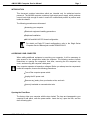
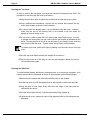
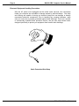
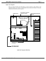
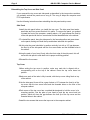
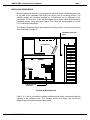
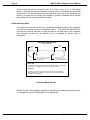
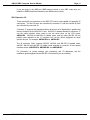
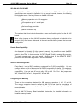
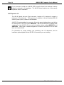
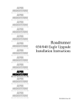
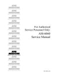
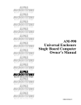
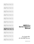
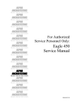
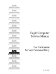
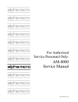
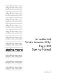
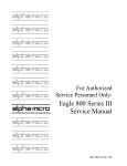
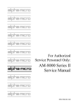
RIGHT. FROM THE START RIGHT. FROM THE START RIGHT. FROM THE START RIGHT. FROM THE START RIGHT. FROM THE START RIGHT. FROM THE START For Authorized Service Personnel Only: AM-990 SBC Service Manual RIGHT. FROM THE START RIGHT. FROM THE START RIGHT. FROM THE START RIGHT. FROM THE START RIGHT. FROM THE START RIGHT. FROM THE START RIGHT. FROM THE START RIGHT. FROM THE START DSS-10524-00, Rev. A01 ALPHA MICROSYSTEMS FCC Notice This equipment has been tested and found to comply with the limits for a Class A digital device, pursuant to Part 15 of the FCC Rules. These limits are designed to provide reasonable protection against harmful interference when the equipment is operated in a commercial environment. This equipment generates, uses and can radiate radio frequency energy and, if not installed and used in accordance with the instruction manual, may cause harmful interference to radio communications. Operation of this equipment in a residential area is likely to cause harmful interference in which case the user will be required to correct the interference at his own expense. Canadian Department of Communications Compliance Statement This equipment does not exceed Class A limits per radio noise emissions for digital apparatus set out in the Radio Interference Regulations of the Canadian Department of Communications. Operation in a residential area may cause unacceptable interference to radio and TV reception requiring the owner or operator to take whatever steps are necessary to correct the interference. Avis de Conformité aux Normes du Ministère des Communications du Canada Cet équipment ne depasse pas les limits de Classe A d’émission de bruits radioélectriques pour les appareils numeriques tels que prescrites par le Règlement sur le brouillage radioélectrique établi par le ministère des Communications du Canada. L’exploitation faite en milleu résidential peut entrainer le brouillage des réceptions radio et tele, ce qui obligerait le propriétaire ou l’opérateur à pendre les dispositions nécessaires pour en éliminer les causes. Battery Warning CAUTION: Danger of explosion if battery is incorrectly replaced. Replace only with the same or equivalent type recommended by the manufacturer. Discard used batteries according to the manufacturer’s instructions. ATTENTION: Il y a danger d’explosion s’il y a remplacement incorrect de la batterie. Remplacer uniquement avec une batterie du même type ou d’un type recommandé par le constructeur. Mettre au rébut les batteries usagées conformément aux instructions du fabricant. For AM-3500-E100, -E200, -E300, -E400, -E500 and AM-990-01 systems, replace battery with Panasonic or Ray-O-Vac BR2325 only. Use of another battery may present a risk of fire or explosion. Replacement batteries may be ordered from your authorized Alpha Micro reseller. For AM-3500-E550, and AM-990-04 systems, replace batteries with Panasonic or Ray-O-Vac BR1225 only. Use of another battery may present a risk of fire or explosion. Replacement batteries may be ordered from your authorized Alpha Micro reseller. Safety Warning This computer contains no user-configurable components that require opening the computer case. Because the power supply in this computer is capable of outputting high current levels hazardous to your safety, the computer case should only be opened by an authorized service technician. Cet ordinateur ne contient aucune pièce configurable par l’utilisateur qui nécessite l’ouverture du boîtier. L’alimentation de cet ordinateur peut produire des nivaeux de tensions dangereux, le boîtier ne devrait donc être ouvert que par un technician autorisé. Electrical Warning This equipment contains components that can be damaged by static electricity. Follow all electronic discharge precautions when handling the equipment. For example, touch the metal back panel of the CPU or peripheral chassis to dissipate any electrical charge before touching the circuit boards or equipment within the chassis. After turning off power, before you open your computer chassis, unplug the cord from the electrical outlet to guard against electrical shock. SOFTWARE SECURITY DEVICE IDENTIFICATION NUMBER: _______________ The Alpha Micro Software Security Device (SSD) is a customized integrated circuit that personalizes the computer, providing identity verification for it. Certain Alpha Micro and non-Alpha Micro software may require that your computer contain an SSD in order to run software that has been customized to run only on your computer. Please enter the identification of your SSD above. The SSD identification number should be on your computer I.D. label under "SSD Serial No." (Another way of finding the number is to look at the SSD itself. The SSD is located in an integrated circuit location on the CPU board; its identification number is printed on the SSD itself.) Software vendors may ask you for the SSD number if they are customizing software to run only on your computer. This document may contain references to products covered under the following U.S. Patent Number(s): 4,530,048 ALPHA MICROSYSTEMS 2722 Fairview St. P.O. Box 25059 Santa Ana, CA 92704 AM-990 SBC Computer Service Manual Page i TABLE OF CONTENTS INTRODUCTION . . . . . . . . . . . . . . . . . . . . . . . . . . . . . . . . . . . . . . . . . . . . . . . . . . . . . 1 ACCESSING YOUR COMPUTER . . . . . . . . . . . . . . . . . . . . . . . . . . . . . . . . . . . . . . . Opening the Front Door . . . . . . . . . . . . . . . . . . . . . . . . . . . . . . . . . . . . . . . . . . Opening the Top Cover . . . . . . . . . . . . . . . . . . . . . . . . . . . . . . . . . . . . . . . . . . Opening the Side Door . . . . . . . . . . . . . . . . . . . . . . . . . . . . . . . . . . . . . . . . . . Electronic Equipment Handling Precautions . . . . . . . . . . . . . . . . . . . . . . . . . . Inside Your Computer . . . . . . . . . . . . . . . . . . . . . . . . . . . . . . . . . . . . . . . . . . . Reinstalling the Top Cover and Side Panel . . . . . . . . . . . . . . . . . . . . . . . . . . . 1 1 2 2 4 5 6 INSTALLING PERIPHERALS . . . . . . . . . . . . . . . . . . . . . . . . . . . . . . . . . . . . . . . . . . . Plastic Mounting Rails . . . . . . . . . . . . . . . . . . . . . . . . . . . . . . . . . . . . . . . . . . . Additional Documentation . . . . . . . . . . . . . . . . . . . . . . . . . . . . . . . . . . . . . . . . 7 8 9 SBC AM-140 CPU BOARD . . . . . . . . . . . . . . . . . . . . . . . . . . . . . . . . . . . . . . . . . . . . . Remote Reset Capability . . . . . . . . . . . . . . . . . . . . . . . . . . . . . . . . . . . . . . . . . Serial I/O Port Configuration . . . . . . . . . . . . . . . . . . . . . . . . . . . . . . . . . . . . . . Configuring SBC Memory . . . . . . . . . . . . . . . . . . . . . . . . . . . . . . . . . . . . . . . . SBC Expansion I/O . . . . . . . . . . . . . . . . . . . . . . . . . . . . . . . . . . . . . . . . . . . . . 10 10 10 10 11 SBC AM-145 CPU BOARD . . . . . . . . . . . . . . . . . . . . . . . . . . . . . . . . . . . . . . . . . . . . . Remote Reset Capability . . . . . . . . . . . . . . . . . . . . . . . . . . . . . . . . . . . . . . . . . Serial I/O Port Configuration . . . . . . . . . . . . . . . . . . . . . . . . . . . . . . . . . . . . . . Configuring SBC Memory . . . . . . . . . . . . . . . . . . . . . . . . . . . . . . . . . . . . . . . . SBC Expansion I/O . . . . . . . . . . . . . . . . . . . . . . . . . . . . . . . . . . . . . . . . . . . . . 13 13 13 13 14 DSS-10524-00, Rev. A01 AM-990 SBC Computer Service Manual Page 1 INTRODUCTION This document contains instructions which are intended only for authorized service personnel. The AM-990 computer contains a high-output power supply, which produces current levels high enough to make it unsafe for unauthorized persons to perform work inside the chassis. The following procedures are discussed: Accessing your computer. Electronic equipment handling precautions. Peripheral installation. AM-140 and AM-145 CPU board configuration. For details on Eagle PC board configurations, refer to the Eagle Series Computer Service Manual,part number DSM-00196-03. ACCESSING YOUR COMPUTER When adding additional equipment or servicing your computer, it will be necessary to gain access to the components inside the computer. The following sections include instructions on opening the computer’s front door, removing the the computer’s top cover, and removing the computer’s side panel. Your computer operates at hazardous voltages. Before you attempt service components inside the computer, observe the following precautions: Turn off the computer power switch. Unplug the AC power cord. Remove any jewelry from your hands, wrists, and neck. Use only insulated or nonconductive tools. Opening the Front Door The factory ships your computer with the door locked. The keys are tiewrapped to your computer’s rear panel, near the power switch. Insert the key, open the lock, and the door will swing open. DSS-10524-00, Rev. A01 Page 2 AM-990 SBC Computer Service Manual Opening the Top Cover In order to remove the side panel, you must first remove the computer’s top cover. The procedure for removing the top cover is as follows: 1.Swing the front door open to expose the screws that hold the top cover in place. 2.Using a phillips-head screwdriver, remove the two screws that connect the top cover to the chassis as shown in the illustration. 3.Don’t worry about the display panel, it is not attached to the top cover. However, make sure the key for the security lock is not inserted in the lock when you attempt to remove the top cover. 4.The top cover is held in place with four locking tabs, one at each corner. In order to release the locking tabs, the top cover must be slid forward as indicated by the arrow. The best way to do this is to use the palm of your hand to firmly strike the rear corners of the top cover. This will cause the top cover to slide forward. To protect your hand, place some type of padding over the rear corners of the top cover. 5.Once the top cover slides forward, pull straight up to remove it. 6.Place the top cover out of the way so it will not get damaged. Make sure you do not bend the locking tabs. Opening the Side Door To install optional boards, disk drives, backup devices, or to service the computer, you’ll need to remove the left side panel as shown in the illustration on the following page: 1.Remove the four screws that secure the left side panel to the chassis. 2.Like the top cover, the left side panel must be slid forward in order to be removed. 3.Using the palm of your hand, firmly strike the rear edge of the side panel as indicated by the arrow. 4.Once the panel slides forward, it can be removed by lifting straight up. 5.As with the top cover, make sure none of the alignment tabs on the side panel get damaged. DSS-10524-00, Rev. A01 AM-990 SBC Computer Service Manual Page 3 LOCKING TABS ER V TOP CO LE FT SI DE PA N MAC4 4 2 EL TO REMOVE THE TOP COVER, REMOVE THESE TWO SCREWS. TO REMOVE THE SIDE PANEL, REMOVE THESE FOUR SCREWS. Removable Top Cover and Side Panel DSS-10524-00, Rev. A01 Page 4 AM-990 SBC Computer Service Manual Electronic Equipment Handling Precautions With the AC power cord unplugged and the sheet metal removed, the components inside your computer are vulnerable to damage caused by static discharge. Your body and clothing are capable of storing an electrical charge that can damage or destroy unprotected electronic components. Prior to handling any computer hardware, make sure your work area is properly protected against static discharge. There are a number of commercially available static protection devices, like the wrist strap shown below, designed specifically to protect your equipment from harmful static discharge. MC1012 Static Protection Wrist Strap DSS-10524-00, Rev. A01 AM-990 SBC Computer Service Manual Page 5 Inside Your Computer Once you have removed the side panel, you will be able to gain access to the equipment inside your computer. The illustration below shows the location of the basic components that make up your computer: TOP ACCESS TO OPTIONAL AUXILIARY I/O PANEL POWER SUPPLY PERIPHERAL MOUNTING AREA COOLING FANS J10 1 CPU BATTERY J2 J1 W8 J18 1 J8 J7 W1 J19 1 SW1 MAC5 7 3 TYPICAL SYSTEM CPU BOARD REAR PANEL ACCESS TO I/O CONNECTORS Inside the Computer (Side View) DSS-10524-00, Rev. A01 Page 6 AM-990 SBC Computer Service Manual Reinstalling the Top Cover and Side Panel If you removed the top cover and side panel as described in the two previous sections, you probably noticed the panels are a snug fit. The snug fit helps the computer meet FCC requirements. Use the following instructions when reinstalling the side panel and top cover: Side Panel 1.Install the side panel before you install the top cover. The side panel has twelve small tabs and four screws that hold it in place. To remove the panel, you pushed it toward the front of the computer, creating about a 1/2" gap between the front lip of the side panel with the four screw holes and the threaded holes in the cabinet. 2.To reinstall the panel, hang the side panel in the forward position and press down on the panel, making sure both the top and bottom tabs slide into position. 3.At this point the panel should be in position vertically, but with a 1/2" gap between the front lip of the side panel with the four screw holes and the threaded holes in the cabinet. 4.Using the palm of your hand, firmly strike the front edge of the side panel; this will cause the side panel to slide back into its proper mounting position. 5.Reinstall the four screws. Top Cover 1.When setting the top cover in position, make sure each tab is aligned with a corresponding slot on the top of the cabinet. Press the top cover down into position. 2.Make sure each of the tabs is fully inserted, with the top cover sitting flush on top of the cabinet. 3.Like the side panel, there will be a gap of about a 1/2" between the front lip of the top cover with the two screw holes and the threaded holes on the front of the computer cabinet. 4.Each corner of the top cover has a notched tab designed to hold the cover in its mounting position. Use the palm of your hand to push the top cover back into position, which will close the gap between the front lip of the top cover and the threaded holes in the cabinet. 5.Install the two screws that secure the top cover to the computer cabinet. DSS-10524-00, Rev. A01 AM-990 SBC Computer Service Manual Page 7 INSTALLING PERIPHERALS Mounting peripheral devices in your computer is simply a matter of attaching plastic rails to the side of the peripheral and sliding the device into its mounting position. The AM-990 chassis has mounting locations for 12 half-height (or six full-height) 5-1/4" peripherals. The front door on the AM-990 chassis has a cutout which allows access to peripheral devices using removable media. This cutout will accommodate up to four 5-1/4" half-height peripherals. The following illustration shows the peripheral mounting area for your computer with the slots numbered 1 through 12. PERIPHERAL MOUNTING AREA COOLING FANS 1 2 3 4 J10 1 5 6 CPU 7 8 BATTERY J2 9 J1 W8 10 J18 1 J8 J7 W1 J19 1 SW1 11 12 MAC5 7 5 TYPICAL SYSTEM CPU BOARD Peripheral Mounting Area Slots 3, 4, 5, and 6 are used for installing peripherals that will be accessed through the opening in the computer door. This includes devices like floppy disk drives and magnetic tape drives that use removable media. DSS-10524-00, Rev. A01 Page 8 AM-990 SBC Computer Service Manual The first hard disk drive is mounted in slot 12, or slots 11 and 12 if it is a full-height device. A second hard disk drive would be mounted in the next available slot above the first disk drive. The hard disk drives are mounted in the lower part of the chassis for two reasons: to make sure the weight in the chassis is properly distributed and to provide easy access for both power and interface cables. Plastic Mounting Rails The plastic mounting rails are the key to installing peripheral devices in your computer. Two rails are required to mount a peripheral device. The rails (DWF-20652-00) are universal; they can be mounted on either the right or left hand side of the peripheral. The illustration showing the rail explains how it is installed on various types of peripherals: PERIPHERAL MOUNTING RAIL DWF-20652-00 LONG END SHORT END Use the top holes for mounting full-height devices. Use the bottom holes for mounting half-height devices. SHORT END For Tandberg 1/4" streaming tape drives and all hard disk drives, mount the rails with the short end pointing toward the rear of the computer cabinet. LONG END For Exabyte 8mm drives, floppy drives, and other drives (except Tandberg) with removable media, mount the rails with the long end pointing toward the rear of the computer cabinet. MAC4 7 0 Peripheral Mounting Rail Besides the rails, the peripheral mounting kit includes both standard and metric screws for compatibility with all of Alpha Micro’s 51/4" peripherals. DSS-10524-00, Rev. A01 AM-990 SBC Computer Service Manual Page 9 DWF-20652-00 MOUNTING RAIL HALF-HIGH 5-1/4" PERIPHERAL MAC4 7 1 Attaching Mounting Rails to Peripheral Additional Documentation Each peripheral device sold by Alpha Micro is covered by its own set of installation instructions. The installation instructions include information on jumper settings, termination, and cabling. Before installing a peripheral, make sure you read the documentation pertaining to the device. If the documentation was not included with your peripheral device, it is also contained on the AlphaCD which is distributed to all Alpha Micro Value Added Resellers on a quarterly basis. DSS-10524-00, Rev. A01 Page 10 AM-990 SBC Computer Service Manual SBC AM-140 CPU BOARD The AM-140 is a 50Mhz main logic board available for the SBC. Most of the AM-140 specifications are covered in Appendix A (in the SBC owner’s manual); however, the following list highlights some of the key features on the AM-140 board: Memory expansion up to 64 megabytes. I/O expansion up to 66 serial ports. On-board intelligent ESDI controller. 68030 Processor chip. The sections that follow include information on user configurable options for the AM-140 board. Most of the jumpers on the AM-140 board are factory configured and should not be moved. Only the features discussed in the next sections have jumpers that are user configurable. Remote Reset Capability As discussed in Appendix B in the owner’s manual, it is possible to reset the SBC remotely through serial I/O Port "0." If properly configured, you can use a push button switch to short Pin 1 in that connector to Pin 7 (Signal Ground), resetting the computer. To enable remote reset, you must install a shorting block in the REMOTE RESET position on the SBC main logic board. See the illustration. Serial I/O Port Configuration Ports 0 and 1 on the SBC are factory configured for RS-232 compatibility. You can configure either or both of these ports for RS-422 compatibility if desired. For each port, three jumpers on the main logic board control whether it is set for RS-232 or RS-422 compatibility. You must set all three to either 232 or 422. For Port 0, the jumpers are W2, W3 and W4; for Port 1, they are W5, W6 and W7. Configuring SBC Memory Installing memory boards in the SBC couldn’t be easier. There are no jumpers to configure, no switches to set, and no concerns with beginning or ending memory addresses. There are four connectors designed for SBC memory boards; J12, J13, J14, and J15. The first memory board is installed in J12; the second memory board is installed in J13; the third goes in J14; and the fourth goes in J15. DSS-10524-00, Rev. A01 AM-990 SBC Computer Service Manual Page 11 If you are going to mix 4MB and 16MB memory boards in your SBC, make sure you install the 16MB boards first followed by the 4MB memory boards. SBC Expansion I/O There are two 60-pin connectors on the SBC CPU board, each capable of supporting 32 serial ports. The first 32 ports are controlled by connector J7 and the second 32 ports are controlled by connector J8. Connector J7 supports the standard interface drivers for all of Alpha Micro’s paddle card devices designed for the AM-355 I/O bus. AM-355 I/O boards attached to connector J7 use the same interface driver used by the two serial ports on the CPU board, AM140.IDV. AM-358 and AM-359 I/O paddle cards, and any other AM-355 I/O bus paddle cards attached to the J7 connector will use the drivers designed for those specific devices. For example: AM358.IDVand AM359.IDV. The J8 connector ONLY supports AM-355, AM-358, and AM-359 I/O paddle cards. AM-355, AM-358 and AM-359 I/O paddle cards attached to connector J8 use special interface drivers: AM355B.IDV, AM358B.IDV and AM359B.IDV. For information on jumper settings, port numbering, and I/O addresses, see the installation guide shipped with the AM-355 I/O bus device you are installing. DSS-10524-00, Rev. A01 Page 12 AM-990 SBC Computer Service Manual PARITY STATUS 1 FRONT PANEL DISPLAY 1 J17 J16 60-PIN ESDI CONNECTOR J15 J14 J13 J12 MEMORY EXPANSION W88 CPU W15 U144 J10 LOW BYTE FLOATING POINT CO-PROCESSOR SOCKET U131 U130 BOOT PROMS HIGH BYTE 36-PIN FLOPPY CONNECTOR 1 50-PIN SCSI CONNECTOR U97 W14 W13 1 J19 POWER CONNECTOR PAL W8 SSD SOCKET J20 W12 NTSC W12 REMOTE RESET JUMPER IN = ENABLED JUMPER OUT = DISABLED J18 60-PIN I/O CONNECTORS 1 J8 U32 W9 W10 BATTERY LINK TERMINATION JUMPER JUMPER IN = ENABLED JUMPER OUT = DISABLED J7 W11 W10 232 / 422 W8 W1 W4 W3 W2 J3 J5 J6 232 / 422 W7 W6 W5 J4 J2 J1 SERIAL PORT 1 SERIAL PORT 0 SW1 MAC4 7 8 VIDEO OUT LINK VIDEO IN VCR REMOTE BOOT SWITCH Option Locations on the AM-140 Board DSS-10524-00, Rev. A01 AM-990 SBC Computer Service Manual Page 13 SBC AM-145 CPU BOARD The AM-145 is a 33Mhz main logic board available for the SBC. Most of the AM-145 specifications are covered in Appendix A in the owner’s manual; however, the following list highlights some of the key features on the AM-145 board: Memory expansion up to 16 megabytes. I/O expansion up to 34 serial ports. On-board floppy controller. 68020 Processor chip. The sections that follow include information on user configurable options for the AM-145 board. Most of the jumpers on the AM-145 board are factory configured and should not be moved. Only the features discussed in the next sections have jumpers that are user configurable. Remote Reset Capability As discussed in Appendix B in the owner’s manual, it is possible to reset the SBC remotely through serial I/O Port "0." If properly configured, you can use a push button switch to short Pin 1 in that connector to Pin 7 (Signal Ground), resetting the computer. To enable remote reset, you must install a shorting block in the REMOTE RESET position on the SBC main logic board. See the illustration. Serial I/O Port Configuration Ports 0 and 1 on the SBC are factory configured for RS-232 compatibility. You can configure either or both of these ports for RS-422 compatibility if desired. For each port, three jumpers on the main logic board control whether it is set for RS-232 or RS-422 compatibility. You must set all three to either 232 or 422. For Port 0, the jumpers are W3, W4 and W5; for Port 1, they are W6, W7 and W8. Configuring SBC Memory There are four connectors designed for SBC memory expansion; J5, J6, J7, and J8. The memory expansion board is called the AM-715-10 and has four megabytes of memory. The maximum memory capacity of 16 megabytes is achieved by installing four memory boards. See the AM-715 Memory Board Installation Instructions, for detailed information on installing memory boards. DSS-10524-00, Rev. A01 Page 14 AM-990 SBC Computer Service Manual If your computer includes an AM-522 ESDI controller board, the maximum memory capacity is reduced to 12 megabytes. The AM-522 board requires one of the memory expansion slots for installation. SBC Expansion I/O The AM-145 board has one 60-pin connector, located at J9, designed to support a maximum of 32 serial ports. These ports are in addition to the two standard AM-145 serial I/O ports (0 and 1) shown in the illustration. AM-355 I/O boards attached to connector J9 use the same interface driver used by the two serial ports on the CPU board, AM145.IDV. AM-358 and AM-359 I/O paddle cards connected to the AM-355 I/O bus use the interface drivers called AM358.IDV and AM359.IDV. Other types of boards designed to be used on the AM-355 I/O bus have their own unique drivers. For information on jumper settings, port numbering, and I/O addresses, see the installation guide shipped with the AM-355 I/O bus device you are installing. DSS-10524-00, Rev. A01 AM-990 SBC Computer Service Manual Page 15 W18 REMOTE RESET JUMPER IN = ENABLED JUMPER OUT = DISABLED FRONT PANEL DISPLAY 1 J8 BATTERY W18 J7 J6 W11 J5 On B. Revison artwork and earlier W100 is hard-wired. MEMORY EXPANSION 1 W100 CPU 1 HIGH BYTE LOW BYTE FLOATING POINT CO-PROCESSOR SOCKET U128 U127 50-PIN SCSI CONNECTOR SSD SOCKET U124 U126 U125 J4 W1 J16 BOOT PROMS J1 1 36-PIN FLOPPY CONNECTOR J2 POWER CONNECTOR W12 2716/2764 W1A W17 W2 W50 W9 1 W17 J9 W13 60-PIN I/O CONNECTORS NTSC / PAL NTSC PAL LINK TERMINATION JUMPER JUMPER IN = ENABLED JUMPER OUT = DISABLED W14 W15 232 / 422 232 / 422 W8 W7 W6 W13 J13 J12 J15 J21 J14 J20 SW1 MAC5 7 6 VIDEO OUT LINK VIDEO IN VCR REMOTE SERIAL PORT 1 SERIAL PORT 0 Option Locations on the AM-145 Board DSS-10524-00, Rev. A01 BOOT SWITCH W5 W4 W3