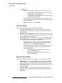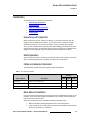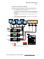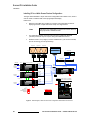
1
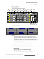
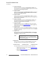
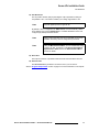
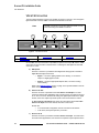
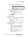
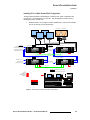
båÅçêÉ=smñ=fåëí~ää~íáçå=dìáÇÉ få=qÜáë=dìáÇÉ This guide provides installation instructions for the Encore VPx. The following topics are discussed in this guide: • • • • • • • • • • Important Installation Notice Change History Copyrights and Notices Company Address Operators Safety Summary Terms and Equipment Marking VPx Overview VPx Hardware Installation Technical Specifications fãéçêí~åí=fåëí~ää~íáçå=kçíáÅÉ== Important Software version 1.22 (or higher) must be installed first in your Encore Controller, prior to connecting your VPx processor(s). Refer to the “Installing VPx” section on page 16 for details. `Ü~åÖÉ=eáëíçêó The table below lists the changes to this guide. Table 1. Change History Rev 00 Date 4/2/08 ECP # 556520 Description Encore VPx Installation Guide Encore VPx Installation Guide • 08-0311105-00 Rev 00 Approved By K. Vogel 1 båÅçêÉ=smñ=fåëí~ää~íáçå=dìáÇÉ Copyrights and Notices `çéóêáÖÜíë=~åÇ=kçíáÅÉë `çéóêáÖÜí © Barco, Inc. April 2, 2008 All rights reserved. No part of this document may be copied, reproduced or translated. It shall not otherwise be recorded, transmitted or stored in a retrieval system without the prior written consent of Barco. kçíáÅÉ Barco provides this manual “as is” without warranty of any kind, either expressed or implied, including but not limited to the implied warranties or merchantability and fitness for a particular purpose. Barco may make improvements and/or changes to the product(s) and/ or the program(s) described in this publication at any time without notice. This publication could contain technical inaccuracies or typographical errors. Changes are periodically made to the information in this publication; these changes are incorporated in new editions of this publication. cÉÇÉê~ä=`çããìåáÅ~íáçåë=`çããáëëáçå=Ec``F=pí~íÉãÉåí This equipment has been tested and found to comply with the limits for a class A digital device, pursuant to Part 15 of the FCC rules. These limits are designed to provide reasonable protection against harmful interference when the equipment is operated in a commercial environment. This equipment generates, uses, and can radiate radio frequency energy and, if not installed and used in accordance with the instruction manual, may cause harmful interference to radio communications. Operation of this equipment in a residential area may cause harmful interference, in which case the user will be responsible for correcting any interference. dì~ê~åíÉÉ=~åÇ=`çãéÉåë~íáçå Barco provides a guarantee relating to perfect manufacturing as part of the legally stipulated terms of guarantee. On receipt, the purchaser must immediately inspect all delivered goods for damage incurred during transport, as well as for material and manufacturing faults Barco must be informed immediately in writing of any complaints. The period of guarantee begins on the date of transfer of risks, in the case of special systems and software on the date of commissioning, at latest 30 days after the transfer of risks. In the event of justified notice of compliant, Barco can repair the fault or provide a replacement at its own discretion within an appropriate period. If this measure proves to be impossible or unsuccessful, the purchaser can demand a reduction in the purchase price or cancellation of the contract. All other claims, in particular those relating to compensation for direct or indirect damage, and also damage attributed to the operation of software as well as to other services provided by Barco, being a component of the system or independent service, will be deemed invalid provided the damage is not proven to be attributed to the absence of properties guaranteed in writing or due to the intent or gross negligence or part of Barco. If the purchaser or a third party carries out modifications or repairs on goods delivered by Barco, or if the goods are handled incorrectly, in particular if the systems are commissioned 2 Encore VPx Installation Guide • 08-0311105-00 Rev 00 båÅçêÉ=smñ=fåëí~ää~íáçå=dìáÇÉ Company Address operated incorrectly or if, after the transfer of risks, the goods are subject to influences not agreed upon in the contract, all guarantee claims of the purchaser will be rendered invalid. Not included in the guarantee coverage are system failures which are attributed to programs or special electronic circuitry provided by the purchaser, e.g. interfaces. Normal wear as well as normal maintenance are not subject to the guarantee provided by Barco either. The environmental conditions as well as the servicing and maintenance regulations specified in this manual must be complied with by the customer. qê~ÇÉã~êâë Brand and product names mentioned in this manual may be trademarks, registered trademarks or copyrights of their respective holders. All brand and product names mentioned in this manual serve as comments or examples and are not to be understood as advertising for the products or their manufactures. `çãé~åó=^ÇÇêÉëë Barco, Inc. 11101 Trade Center Drive Rancho Cordova, California 95670 USA • • • Phone: (916) 859-2500 Fax: (916) 859-2515 Website: www.barco.com Barco N.V. Noordlaan 5 8520 Kuurne BELGIUM • • Phone: +32 56.36.82.11 Fax: +32 56.35.16.51 Technical Support • • Tech Line: (866) 374-7878 — 24 hours per day, 7 days per week E-mail: [email protected] Encore VPx Installation Guide • 08-0311105-00 Rev 00 3 båÅçêÉ=smñ=fåëí~ää~íáçå=dìáÇÉ Operators Safety Summary léÉê~íçêë=p~ÑÉíó=pìãã~êó The general safety information in this summary is for operating personnel. aç=kçí=oÉãçîÉ=`çîÉêë=çê=m~åÉäë There are no user-serviceable parts within the unit. Removal of the top cover will expose dangerous voltages. To avoid personal injury, do not remove the top cover. Do not operate the unit without the cover installed. mçïÉê=pçìêÅÉ This product is intended to operate from a power source that will not apply more than 230 volts rms between the supply conductors or between both supply conductor and ground. A protective ground connection by way of grounding conductor in the power cord is essential for safe operation. dêçìåÇáåÖ=íÜÉ=mêçÇìÅí This product is grounded through the grounding conductor of the power cord. To avoid electrical shock, plug the power cord into a properly wired receptacle before connecting to the product input or output terminals. A protective-ground connection by way of the grounding conductor in the power cord is essential for safe operation. rëÉ=íÜÉ=mêçéÉê=mçïÉê=`çêÇ Use only the power cord and connector specified for your product. Use only a power cord that is in good condition. Refer cord and connector changes to qualified service personnel. rëÉ=íÜÉ=mêçéÉê=cìëÉ To avoid fire hazard, use only the fuse having identical type, voltage rating, and current rating characteristics. Refer fuse replacement to qualified service personnel. aç=kçí=léÉê~íÉ=áå=bñéäçëáîÉ=^íãçëéÜÉêÉë To avoid explosion, do not operate this product in an explosive atmosphere. 4 Encore VPx Installation Guide • 08-0311105-00 Rev 00 båÅçêÉ=smñ=fåëí~ää~íáçå=dìáÇÉ Terms and Equipment Marking qÉêãë=~åÇ=bèìáéãÉåí=j~êâáåÖ= t^okfkd Highlights an operating procedure, practice, condition, statement, etc., which, if not strictly observed, could result in injury to or death of personnel. Note Highlights an essential operating procedure, condition or statement. `^rqflk The exclamation point within an equilateral triangle is intended to alert the user to the presence of important operating and maintenance (servicing) instructions in the literature accompanying the appliance. ^sboqfppbjbkq> Le point d´exclamation dans un triangle equilatéral signale à alerter l´utilisateur qu´il y a des instructions d´operation et d´entretien tres importantes dans la litérature qui accompagne l´appareil. slopf`eq Ein Ausrufungszeichen innerhalb eines gleichwinkeligen Dreiecks dient dazu, den Benutzer auf wichtige Bedienungs-und Wartungsanweisungen in der Dem Great beiliegenden Literatur aufmerksam zu machen. Encore VPx Installation Guide • 08-0311105-00 Rev 00 5 båÅçêÉ=smñ=fåëí~ää~íáçå=dìáÇÉ VPx Overview smñ=lîÉêîáÉï The following topics are discussed in this section: • • • • Introduction to VPx Input Flexibility Scaling and Keying Output Flexibility fåíêçÇìÅíáçå=íç=smñ The Encore Video Processor is a compact chassis that provides Encore’s input and output circuitry. Two models are available: • The “standard” Video Processor (VP) is a full-featured unit that includes all input, output, genlock and link circuitry. • The VPx is an economical VP with a reduced set of inputs (DVI only). The VPx is ideal for widescreen configurations, and for special widescreen “preview” configurations. VPx includes all output and link circuitry, but no genlock circuitry, and only a small subset of the standard VP’s input circuitry. • In a widescreen configuration, a VPx cannot function in a standalone manner, but must always work downstream of a standard VP. Here, a VPx cannot be the first processor in an Encore configuration. • In the special widescreen “preview” configuration, a VPx can be used as a standalone destination that accepts DVI input signals only — but no other input types are accepted, and no genlock circuitry is provided. Both units provide a 3RU rack-mount chassis that can be configured with one, two or three M/E (mixer) boards. One or two M/E systems can be upgraded with additional M/E boards. fåéìí=cäÉñáÄáäáíó The figure below illustrates a block diagram of the VPx’s M/E. VPx M/E Board Source Link Scaler A DVI Background Channel Mixer Source Link Scaler B DVI Background Channel Figure 1. M/E Board Block Diagram, VPx The VPx accepts computer input resolutions up to 1920 x 1200, via DVI. 6 Encore VPx Installation Guide • 08-0311105-00 Rev 00 båÅçêÉ=smñ=fåëí~ää~íáçå=dìáÇÉ VPx Overview pÅ~äáåÖ=~åÇ=hÉóáåÖ For the VPx, the Athena scaler features the following: • • • • • 1:1 pixel sampling 3:2 and 2:2 pull down detection Aspect ratio correction and image cropping Real-time window resizing and positioning Full support for seamless transitions, window borders, drop shadows and keying lìíéìí=cäÉñáÄáäáíó Each Encore VPx incorporates one output board, which provides all output interface functions as well as the blending and data-doubling functions required to support wide screen applications. Supported output resolutions include: • • • • • Computer output resolutions up to 1600 x 1200 Analog HDTV resolutions including 720p, 1080i, 1080p HD-SDI video 2048 x 1080p digital cinema video Plasma display resolutions. Encore VPx Installation Guide • 08-0311105-00 Rev 00 7 båÅçêÉ=smñ=fåëí~ää~íáçå=dìáÇÉ VPx Hardware smñ=e~êÇï~êÉ The following topics are discussed in this section: • • • • • • VPx Front Panel VPx Rear Panel VPx M/E Connectors M/E Connector Priority M/E Input Notes Program Output Notes smñ=cêçåí=m~åÉä The figure below illustrates the VPx front panel: 1 2 3 Visibly yours Folsom ENCORE VPx Figure 2. VP Front Panel 1) 2) Chassis Handles Air Intake Ports 3) Status LED Following are descriptions of each front panel control feature: 1) Chassis Handles Two Chassis Handles are provided for ease of installation and transportation. When transporting the chassis by its handles, do not set it down with the rear connectors towards the ground. If you do, you may damage the rear connectors. 2) Air Intake Ports Two Air Intake Ports are provided for chassis cooling. The direction of airflow is from the front to the rear. To prevent overheating, do not block the air intake ports. 3) Status LED The Status LED, behind the right-hand Air Intake Port, indicates the following: ~ ~ ~ 8 Solid Red: the unit is initializing Solid Green: the unit is ready for use Blinking Red: an error has occurred Encore VPx Installation Guide • 08-0311105-00 Rev 00 båÅçêÉ=smñ=fåëí~ää~íáçå=dìáÇÉ VPx Hardware smñ=oÉ~ê=m~åÉä The figure below illustrates the VPx rear panel: 1 DVI 2 PREVIEW 3 Hol es Hol es ANALOG ANALOG 4 5 6 7 8 9 10 Hol es PROGRAM 2 DVI DVI PROGRAM 1 ANALOG HD / SDI OUT PROGRAM LINK IN ETHERNET 11 INPUT 1B INPUT 1A DVI OUT SOURCE LINK 1 IN 1 DVI UNIT ID 12 13 INPUT 2B INPUT 2A DVI OUT SOURCE LINK 2 IN DVI DVI OUT SOURCE LINK 3 IN DVI SERIAL INPUT 3B INPUT 3A 14 15 16 Figure 3. VPx Rear Panel 1) Preview Out DVI 7) Program Out HD/SDI 13) M/E 3 Connectors 2) Preview Out Analog 8) Program Link Out 14) Unit ID Selector 3) Program 2 Out Analog 9) Program Link In 15) Serial Port 4) Program 2 Out DVI 10) Ethernet Port 16) AC Connector 5) Program 1 Out DVI 11) M/E 1 Connectors 6) Program 1 Out Analog 12) M/E 2 Connectors Please note: • Connectors 1 through 10 are part of the VPx’s output board, and all output connections are standard. All program and preview DVI output connectors are digital only. • In a widescreen configuration, a VPx cannot function in a standalone manner, but must always work downstream of a standard VP. Here, a VPx cannot be the first processor in an Encore configuration. • In the special widescreen “preview” configuration, a VPx can be used as a standalone destination that accepts DVI input signals only — but no other input types are accepted, and no genlock circuitry is provided. • This guide does not provide connector pinouts. Refer to Appendix A in the Encore Presentation System User’s Guide for details. Following are descriptions of each rear panel connector and section on the VPx. 1) Preview Out DVI One DVI connector is provided for Digital Preview Output. 2) Preview Out Analog One 15-pin D connector is provided for Analog Preview Output. Encore VPx Installation Guide • 08-0311105-00 Rev 00 9 båÅçêÉ=smñ=fåëí~ää~íáçå=dìáÇÉ VPx Hardware 3) Program 2 Out Analog One 15-pin D connector is provided for the Analog Program 2 Output. This output is identical to the analog Program 1 Output, except that it does not include edge feathering and data doubling components. 4) Program 2 Out DVI One DVI connector is provided for the Digital Program 2 Output. This output is identical to the digital Program 1 Output, except that it does not include edge feathering and data doubling components. 5) Program 1 Out DVI One DVI connector is provided for the Digital Program 1 Output. This output includes all edge feathering and data doubling components, and is designed for a digital connection to your projector. 6) Program 1 Out Analog One 15-pin D connector is provided for the Analog Program 1 Output. This output includes all edge feathering and data doubling components, and is designed for an analog connection to your projector. 7) Program Out HD/SDI One BNC connector is provided for the HD/SDI (High Definition/Serial Digital Interface) output. Refer to the “Program Output Notes” section on page 14 for additional information on video outputs. 8) Program Link Out One DVI connector is provided for the Program Link Output. To ensure proper data doubling in wide screen configurations, this output connects to the Program Link Input on another VPx. 9) Program Link In One DVI connector is provided for the Program Link Input. To ensure proper data doubling in wide screen configurations, this input connects to the Program Link Output from another VP (or VPx). Note In Chapter 3 “Installation” of the Encore Presentation System User’s Guide, refer to the “Program and Source Link Connections” section for details on the link connectors in wide screen configurations. 10) Ethernet Port One RJ-45 connector is provided for 10/100BaseT Ethernet communications. For multiple connections, use an Ethernet switch on an isolated network. 11) M/E 1 Connectors 12) M/E 2 Connectors 13) M/E 3 Connectors Six analog and digital connectors are provided for each M/E. Please note: 10 ~ All M/E boards are identical on a VPx. See the “VPx M/E Connectors” section on page 12 for details. ~ Refer to the “M/E Connector Priority” section on page 13 for important information on connector priority. Encore VPx Installation Guide • 08-0311105-00 Rev 00 båÅçêÉ=smñ=fåëí~ää~íáçå=dìáÇÉ VPx Hardware 14) Unit ID Selector One 16-position selector (with physical digits 0 - 15) is provided for setting an unique ID on a VPx The selector enables you to assign logical IDs 1 to 16. Note Physical digit 0 equates to logical ID 16. By default, a VPx is configured as an DHCP Client, and it automatically obtains an IP address when it sees a DHCP Server. Controller Models SC and LC are configured (by default) as DHCP Servers. Note Always ensure that each VPx has a unique ID. During setup, the ID is used during various configuration procedures. Note Using the Miscellaneous Menu, you can re-define IDs using numbers 17 - 32. In Chapter 5 of the Encore Presentation System User’s Guide, refer to the “Miscellaneous Menu” section for details. 15) Serial Port One 9-pin D connector is provided for RS-232 serial communications with VPx. 16) AC Connector One AC Connector is provided to connect the VPx to your AC source. See the “Program Output Notes” section on page 14 for more information on VPx outputs. Encore VPx Installation Guide • 08-0311105-00 Rev 00 11 båÅçêÉ=smñ=fåëí~ää~íáçå=dìáÇÉ VPx Hardware smñ=jLb=`çååÉÅíçêë The figure below illustrates a close-up of the M/E connectors on the VPx. Even though the figure uses M/E 1’s board, all M/E connections are identical on the VPx. Note The M/E connectors on a VPx are identical to those on a VP, minus the analog and HD/SDI connectors. a b DVI OUT c d INPUT 1A INPUT 1B SOURCE LINK 1 IN DVI Figure 4. VPx M/E Connectors a) DVI Input A c) b) Source Link Out Source Link In d) DVI Input B On each M/E, one input connection is provided for layer A, one for layer B, and two “Link” connectors for inter-Processor communications. Following are descriptions of each M/E connector on a VPx. a) DVI Input A One DVI-I connector is provided for both digital and analog inputs to the M/E’s Layer A and background channel. ~ Digital — connect a digital graphics source directly, or connect the output of a digital graphics router. ~ Analog — using the appropriate adapter cable, connect an analog source directly. Refer to the “M/E Input Notes” section on page 14 for important details on the use of this connector’s analog component. b) Source Link Out One DVI connector is provided for the M/E’s Source Link Output. For wide screen and multi-screen applications, this connector loops your inputs to the next VP or VPx in the chain. Because all analog and digital inputs reside in the digital domain, each “link” output loops those inputs to the next Processor’s scalers. An M/E’s Source Link Output must always be connected to its associated M/E Source Link Input on the next chassis, and never cross-routed. Please note: ~ ~ c) In a multi-chassis configuration, the link can extend to all chassis. In all cases, the looped inputs are “pre-scaler.” Source Link In One DVI connector is provided for the M/E’s Source Link Input. For wide screen and multi-screen applications, this connector accepts the looped outputs from the 12 Encore VPx Installation Guide • 08-0311105-00 Rev 00 båÅçêÉ=smñ=fåëí~ää~íáçå=dìáÇÉ VPx Hardware previous VP or VPx in the chain. An M/E’s Source Link Input must always be connected to its associated M/E Source Link Output on the previous chassis, and never cross-routed. Note d) In Chapter 3 “Installation” of the Encore Presentation System User’s Guide, refer to the “Program and Source Link Connections” section for details on the link connectors in wide screen configurations. DVI Input B One DVI-I connector is provided for both digital and analog inputs to the M/E’s Layer B and background channel. ~ Digital — connect a digital graphics source directly to this input, or connect the output of a digital graphics router. ~ Analog — using the appropriate adapter cable, connect an analog source directly to this input. Refer to the “M/E Input Notes” section on page 14 for details on the use of this connector’s analog component. jLb=`çååÉÅíçê=mêáçêáíó Depending on your VP or VPx configuration, the M/E connectors on the rear of the chassis do not necessarily relate 1:1 to the layer buttons in the Controller’s Layer Control Section. Please note: • The Controller’s layer buttons are arranged left-to-right in order of visual priority, from the lowest (Mixer 1) to the highest (Mixer 3). • The M/E boards are arranged in order of electronic priority, from the lowest (M/E 3) to the highest (M/E 1). • Electronic priority does not equate 1:1 to visual priority, with regard to the silkscreened labels on the Controller. With this in mind, the information below lists how the physical connectors relate to the various mixers on different VP and VPx configurations. Keep this correlation in mind when you are making rear-panel connections. • • In a 3 M/E system: ~ M/E 1 connectors are the highest priority. They appear as Mixer 3 on the Controller. The DSK will be connected to the M/E 1 board. ~ ~ M/E 2 connectors have middle priority. They appear as Mixer 2. M/E 3 connectors are the lowest priority. They appear as Mixer 1. Background sources will be connected to the M/E 3 board. In a 2 M/E system: ~ M/E 1 connectors are the highest priority, and appear as Mixer 2. The DSK will be connected to the M/E 1 board. ~ M/E 2 connectors are the lowest priority, and appear as Mixer 1. Background sources will be connected to the M/E 2 board. ~ M/E 3 connectors are not installed. Encore VPx Installation Guide • 08-0311105-00 Rev 00 13 båÅçêÉ=smñ=fåëí~ää~íáçå=dìáÇÉ VPx Hardware • In a 1 M/E system: ~ M/E 1 connector priorities are relative to the connectors being used: • The DVI Input A or Analog Input A connector could be set up as a Background input (lowest priority). • The DVI Input B or Analog Input B connector could be setup as a DSK input (highest priority). This leaves the other connectors to fall in between Background and DSK. The rule stating that “A” connectors are lower in priority than “B” connectors still holds. ~ M/E 2 and 3 connectors are not installed. jLb=fåéìí=kçíÉë Please note the following important points regarding M/E inputs: • Single Processor Configurations — In the special widescreen “preview” configuration, a VPx can be used as a standalone destination that accepts DVI input signals only. • Multiple Processor Configurations — In these configurations, you only need to connect inputs to the first VP. Inputs are automatically looped to all other VP and VPx units via the Source Link connections. • DVI-I Connectors — There are two DVI-I connectors for each M/E (A and B), and each contains a digital and an analog input. Depending upon your application, you can use the input for a scaled or an unscaled source: ~ The “digital” side accepts connections from a standard DVI output or digital graphic router. This side can be used as both a scaled input source or as an unscaled Background / DSK source. ~ Using a breakout cable, the “analog” side accepts analog connections. This side is designed for inputting the system’s unscaled sources — Background and DSK. • The lowest priority M/E in your system must be used for inputting the Background source. • The highest priority M/E in your system must be used for inputting the DSK source. mêçÖê~ã=lìíéìí=kçíÉë Please note the following important points regarding the Processor’s program outputs: 14 • HD/SDI Outputs — For the HD/SDI output, you can set the output to be SDI (SMPTE 259M-C, NTSC or PAL) or HD-SDI (SMPTE 292M, HDTV). When you set this output resolutions, all output connectors will output that same resolution. • DVI Program Outputs — DVI Program outputs are digital only. They do not have analog connections. • Program 1 Outputs — Edge feathering and data doubling are present on all Program 1 Outputs, provided that those features are enabled in the system’s Output Menu. Encore VPx Installation Guide • 08-0311105-00 Rev 00 båÅçêÉ=smñ=fåëí~ää~íáçå=dìáÇÉ Installation fåëí~ää~íáçå The following topics are discussed in this section: • • • • • Unpacking and Inspection Site Preparation Cable and Adapter Information Rack-Mount Installation Installing VPx råé~ÅâáåÖ=~åÇ=fåëéÉÅíáçå= Before opening the VPx box, inspect it for damage. If you find any damage, notify the shipping carrier immediately for all claims. As you open the box, compare its contents against the packing slip. If you find any shortages, contact your sales representative. Once you have removed all the components from their packaging and checked that all the components are present, visually inspect each unit to ensure there was no damage during shipping. If there is damage, notify the shipping carrier immediately for all claims. páíÉ=mêÉé~ê~íáçå= The environment in which you install your VPx units should be clean, properly lit, free from static, and have adequate power, ventilation, and space for all components. `~ÄäÉ=~åÇ=^Ç~éíÉê=fåÑçêã~íáçå The table below provides information regarding cables and adapters: Table 2. VPx cables and adapters Quantity Cable / Adapter Description 1 M/E 2 M/E 3 M/E Power (US) 18GA, 10A, 7.5 meter length 1 1 1 DVI-I Male to DVI-I Male 1 meter length 2 3 4 DVI Plug to VGA Cable Adapter 2 4 4 o~ÅâJjçìåí=fåëí~ää~íáçå Encore VPx units are designed to be rack mounted, and are supplied with front rack-mount hardware. Rear rack-mount brackets are available as a kit, and are recommended when units are mounted in transit cases. When rack mounting VPx units, remember the following important points: • • Maximum ambient operating temperature for the unit is 40 degrees C. Leave at least one inch of space (front and rear) to ensure that the airflow through the fan and vent holes is not restricted. Encore VPx Installation Guide • 08-0311105-00 Rev 00 15 båÅçêÉ=smñ=fåëí~ää~íáçå=dìáÇÉ Installation • Distribute the units evenly to prevent hazardous conditions that may be created by uneven weight distribution. • Rack mount the units from the front rack ears using four rack screws (not supplied). Threads may be metric or otherwise — depending upon the rack type. • Install the lower of the two mounting holes first. fåëí~ääáåÖ=smñ This section provides detailed VPx installation procedures for the Encore configurations listed below. Select the desired configuration, and follow all steps. Important Only valid VPx configuration procedures are included below. Note that steps for connecting peripherals (e.g., ScreenPROII, Aux destinations, routers, tally, D/As, etc.) in a system are not covered below, but are fully covered in Chapter 3 of the Encore Presentation System User’s Guide. Important Software version 1.22 (or higher) must be installed first in your Encore Controller, prior to connecting your VPx processor(s). Refer to Appendix C, “Upgrading Software” in the Encore Presentation System User’s Guide for complete upgrade instructions. The following installation procedures are provided: • • • 16 Installing VPX in a Wide Screen Configuration Installing VPx in a Wide Screen Preview Configuration Installing VPx in a Wide Screen Stack Configuration Encore VPx Installation Guide • 08-0311105-00 Rev 00 båÅçêÉ=smñ=fåëí~ää~íáçå=dìáÇÉ Installation fåëí~ääáåÖ=smu=áå=~=táÇÉ=pÅêÉÉå=`çåÑáÖìê~íáçå The figure below illustrates a block diagram of a “triple” wide screen configuration that includes VPx. Use this diagram for reference in the following procedure. Please note: • • Aux destinations are not shown in the diagram. • A VP must be used as the “master” processor. Thereafter, either a VP or a VPx can be used. • Software version 1.22 (or higher) must be installed first in your Encore Controller, prior to connecting your VPx processor(s). This procedure can be used for wide screen configurations consisting of from 2 to 32 screens. Horizontal, vertical, and “array” blending is set using the Destination Setup Menu. Program #1 Program #2 Preview #1 M/E Inputs VP #1 Projector #1 Program #3 Preview #2 Projector #2 Projector #3 Preview #3 Note: #1 is VP only, not VPx Scaled Sources PG 2 PVW Unscaled Sources PG 1 VP or VPx #2 Program Link Source Link Important: PG 2 Software version 1.22 (or higher) must be installed in the Controller . PVW Unscaled Sources PG 1 VP or VPx #3 Program Link Source Link PG 2 PVW Unscaled Sources PG 1 To: Routers ScreenPRO-II PresentationPRO-II ImagePRO Ethernet Switch Controller SC or LC Figure 5. Block Diagram, Wide Screen Encore Configuration Encore VPx Installation Guide • 08-0311105-00 Rev 00 17 båÅçêÉ=smñ=fåëí~ää~íáçå=dìáÇÉ Installation For this procedure, you will need: Table 3. Equipment List, Wide Screen Encore Configuration Qty. Item Note 1 VP VPx cannot be used as the “master” processor 2 VP or VPx Use either processor as a “slave” unit in a widescreen configuration 1 Controller Model LC or SC 3 Video Projectors Customer supplied. 6 DVI or Analog Monitors Program and Preview (customer supplied). 1 Ethernet Switch Customer supplied 4 Ethernet cables Customer supplied. Additional cables required for routers. TBD Program Link Cables Use 1 for double wide screen application, left justification Use 2 for triple wide screen application, left justification Use 2 for double wide screen application, center justification Use 3 for triple wide screen application, center justification TDB Source Link Cables Dependent on the number of M/Es installed in the Processors TBD Sources, routers and cables Analog, Video and/or DVI as required (customer supplied) Use the following steps to install a wide screen Encore configuration that includes VPx: 1. Software Version — Prior to connecting your VPx processor(s), ensure that software version 1.22 (or higher) is installed in your Encore Controller. Refer to Appendix C, “Upgrading Software” in the Encore Presentation System User’s Guide for complete upgrade instructions. 2. Follow the unpacking procedures as listed in the “Unpacking and Inspection” section on page 15. 3. Refer to the “Technical Specifications” section on page 28 for electrical and mechanical details. 4. Refer to the “VPx Hardware” section on page 8 for all connector locations. 5. For each VPx, follow the rack mount procedures as outlined in the “Rack-Mount Installation” section on page 15. 6. Ethernet Connections — a totally “local” network connection is recommended. Connect the VP(s), VPx(s) and Controller to the Switch. 7. Direct Source Connections — if you elect to use direct connections, in place of (or in addition to) router connections: a. Connect the desired “direct” sources to each M/E’s input connectors on each VPx. In a wide screen system, scaled sources only connect to Processor 1. “Links” carry the signals to the other VPx units. b. Unscaled Backgrounds must originate from computers with multi-head graphics cards, and connect to the same input on each VPx. S To connect an unscaled background source in a triple processor system (each VPx with three M/Es): • 18 Connect the computer’s “head 1” to processor 1, input 3A Encore VPx Installation Guide • 08-0311105-00 Rev 00 båÅçêÉ=smñ=fåëí~ää~íáçå=dìáÇÉ Installation • Connect the computer’s “head 2” to processor 2, input 3A • Connect the computer’s “head 3” to processor 3, input 3A Note c. Input 3A resides on the lowest priority M/E in a 3 M/E system. To connect a second background, use input 3B. The DSK source may originate from a computer with a multi-head graphics card, but it is not a requirement. To use a multi-head graphics card for the DSK, connect it to the same input on each VPx — to the highest priority M/E (M/E 1). S To connect an unscaled DSK source in a triple processor system (each processor with three M/Es): Note 8. Connect the computer’s “head 1” to processor 1, input 1A • Connect the computer’s “head 2” to processor 2, input 1A • Connect the computer’s “head 3” to processor 3, input 1A Input 1A resides on the highest priority M/E in a 3 M/E Encore system. If you wish to connect a backup DSK, use input 1B. Output Connections — a. For each VPx, connect the analog or digital Preview Output to the input of the associated Preview Monitor. b. For each VPx, connect the analog or digital Program 2 Output to the input of the associated Program Monitor. c. For each VPx, connect the analog or digital Program 1 Output to the input of the associated projector. d. Connect the Program Out HD/SDI connector to an SDI or HDTV monitor as required, or to the proper video distribution equipment. Note 9. • This output only works if the selected output resolution is a valid SDI or HD/SDI format. Link Connections — in a widescreen application, the Program Link and Source Link connections are used to connect processors together, and bridge inputs and outputs for the proper “overlap” between projectors. In Chapter 3 of the Encore Presentation System User’s Guide, refer to the “Program and Source Link Connections” section for details. 10. Power Connection — connect AC power cords to all Encore and peripheral equipment, and then to AC outlets. 11. System ID — Using the Unit ID Selector, set the ID of Processor #1 to 1, Processor #2 to 2, and Processor #3 to 3. Each unit must have a unique ID. Remember that you can redefine IDs using numbers 17 - 32 from the Miscellaneous Menu. 12. Power On — Refer to Chapter 6 of the Encore Presentation System User’s Guide for all power on instructions. Encore VPx Installation Guide • 08-0311105-00 Rev 00 19 båÅçêÉ=smñ=fåëí~ää~íáçå=dìáÇÉ Installation fåëí~ääáåÖ=smñ=áå=~=táÇÉ=pÅêÉÉå=mêÉîáÉï=`çåÑáÖìê~íáçå The figure below illustrates a “triple” wide screen configuration that includes a VPx, which is used to create a combined wide screen program/preview display. Please note: • Because a three M/E VPx provides up to 6 PIPs, this configuration is ideal for displaying a double or triple wide screen setup on a single monitor. Note This is the only configuration in which a VPx can be used in a single processor, standalone mode. • For configurations using more than three processors, additional dedicated “preview” processors may be required, along with additional monitors. • Software version 1.22 (or higher) must be installed first in your Encore Controller, prior to connecting your VPx processor(s). Projector #1 Projector #2 Projector #3 Widescreen Program Video Recorder Widescreen Preview ImagePRO M/E Inputs VP #1 Note: #1 is VP only, not VPx PG 2 (Analog) Scaled Sources Scaler Inputs PG 2 (DVI) PVW (Analog) Unscaled Sources PVW (DVI) PG 1 VP or VPx #2 Program Link VP or VPx #4 1A 1B 2A 2B 3A 3B Source Link PG 2 (Analog) PG 2 (DVI) PVW PG 1 PVW (Analog) Unscaled Sources Note: DVI connections only PVW (DVI) PG 1 VP or VPx #3 Program Link Source Link Important: PG 2 (Analog) Software version 1.22 (or higher) must be installed in the Controller. PG 2 (DVI) PVW (Analog) Unscaled Sources PVW (DVI) PG 1 To: Routers ScreenPRO-II PresentationPRO-II ImagePRO Ethernet Switch Controller SC or LC Figure 6. Block Diagram, Wide Screen Encore Configuration with Wide Screen Preview 20 Encore VPx Installation Guide • 08-0311105-00 Rev 00 båÅçêÉ=smñ=fåëí~ää~íáçå=dìáÇÉ Installation Please note the following points regarding this configuration: • Processor #4 (VPx) receives DVI Program and Preview feeds from processors #1, #2 and #3. • Using Processor #4, three PIPs are scaled and positioned to create the wide screen Program display, and three more are scaled to create the Preview display. PIP 1A PIP 2A PIP 3A Wide Screen Program Wide Screen Preview PIP 1B PIP 2B PIP 3B Figure 7. Wide Screen Program/Preview Monitor PIPs • Processor #4’s Preview output is routed to the display for viewing the combined wide screen program/preview output. • Processor #4’s Program output is routed to an ImagePRO for scaling, and then to an SDI or HD-SDI recorder. In addition to the equipment listed in Table 3 on page 18, you will also need the following equipment for this setup: Table 4. Equipment List, Additional Wide Screen Program/Preview Requirements Qty. Item Note 1 VPx Assigned as Video Processor #4 1 DVI or Analog Monitor For wide screen program/preview display 1 Ethernet cable Customer supplied 6 DVI interconnect cables Inputs to video processor #4 (customer supplied) 2 Interconnect cables Video processor #4 outputs (Analog, Video and/or DVI as required) 1 ImagePRO Optional, for use as output scaler (customer supplied) 1 SDI or HD-SDI Video Recorder Optional, to record combined wide screen output (customer supplied) Use the following steps to install an Encore system that includes a VPx, for a combined wide screen program/preview display: 1. Software Version — Prior to connecting your VPx processor(s), ensure that software version 1.22 (or higher) is installed in your Encore Controller. Refer to Appendix C, “Upgrading Software” in the Encore Presentation System User’s Guide for complete upgrade instructions. 2. Follow all steps to install a Wide Screen Application, as outlined in the “Installing VPX in a Wide Screen Configuration” section on page 17. You do not need to install the six individual monitors for program and preview displays, because you will be using one monitor instead. Encore VPx Installation Guide • 08-0311105-00 Rev 00 21 båÅçêÉ=smñ=fåëí~ää~íáçå=dìáÇÉ Installation 3. Rack mount processor #4. 4. Connect Ethernet from processor #4 to the Ethernet Switch. 5. Source Connections — connect DVI outputs from processors one, two and three to processor #4’s scaler inputs: 6. ~ ~ ~ ~ ~ ~ Connect processor #1 DVI Program 2 output to processor #4 input 1A. Note Program 2 output is used because it is a clean feed, without any edge feathering or data doubling in the signal. Connect processor #1 DVI Preview 2 output to processor #4 input 1B. Connect processor #2 DVI Program 2 output to processor #4 input 2A. Connect processor #2 DVI Preview 2 output to processor #4 input 2B. Connect processor #3 DVI Program 2 output to processor #4 input 3A. Connect processor #3 DVI Preview 2 output to processor #4 input 3B. Output Connections — ~ Connect processor #4’s analog or digital Preview Output to the input of your widescreen preview monitor. ~ (Optional, for video recording) Connect processor #4’s analog or digital Program Output 1 or 2 to the input of the ImagePRO. Connect the ImagePRO’s output to the input of your recorder. Refer to the “ImagePRO User’s Guide” for connection and setup details. 7. Power Connection — connect AC power cords to the AC Power connectors on the rear of processor #4, the monitor and the ImagePRO. 8. System ID — Using the Unit ID Selector, set the ID of processor #4 to 4. Note 9. Power On — Refer to Chapter 6 of the Encore Presentation System User’s Guide for all power on instructions. Important 22 Each processor must have a unique ID. In order to properly configure processor #4 and its Preview output, several important setup steps must be taken at the Controller. For full instructions, in Chapter 3 of the Encore Presentation System User’s Guide, refer to the “Completing Wide Screen Preview Setup” section. Encore VPx Installation Guide • 08-0311105-00 Rev 00 båÅçêÉ=smñ=fåëí~ää~íáçå=dìáÇÉ Installation fåëí~ääáåÖ=smñ=áå=~=táÇÉ=pÅêÉÉå=pí~Åâ=`çåÑáÖìê~íáçå The figure below illustrates a block diagram of a wide screen “stack” configuration that includes VPx. Aux destinations are not shown. Use this diagram for reference in the following procedure. Please note: • Software version 1.22 (or higher) must be installed first in your Encore Controller, prior to connecting your VPx processor(s). Projector #1 Program #1 Preview #1 M/E Inputs VP #2 (ID #2) Projector #2 Program #2 Preview #2 Note: #2 is VP only M/E Inputs VP or VPx #4 (ID #4) Scaled Sources 7 - 12 Top Stack #1 Unscaled Srcs (DSK) 1A, 1B Background (BG) Input 3B Background (BG) Input 3A PG 2 (DSK) 1A, 1B PVW BG Input 3B PG 1 BG Input 3A Top Stack #2 PG 2 PVW PG 1 Program Link Source Link VP #1 (ID #1) Scaled Sources 1 - 6 Note: #1 is VP only Bottom Stack #1 Unscaled Sources (Backgrounds) 3A, 3B VP or VPx #3 (ID #3) Bottom Stack #2 PG 2 (DVI) PVW (DVI) (Backgrounds) 3A, 3B PG 2 (DVI) PVW (DVI) Program Link Source Link Important: To: Software version 1.22 (or higher) must be installed in the Controller. Routers ScreenPRO-II PresentationPRO-II ImagePRO Ethernet Switch Controller LC Only Figure 8. Block Diagram, Wide Screen Stack Configuration Encore VPx Installation Guide • 08-0311105-00 Rev 00 23 båÅçêÉ=smñ=fåëí~ää~íáçå=dìáÇÉ Installation For this procedure, you will need: Table 5. Equipment List, Wide Screen Stack Configuration Qty. Item Note 2 VP Master units (ID#1 and ID#2) must be VP, not VPx. 2 VP or VPx The ID of the bottom stack processor must always be lower than the ID of the top stack processor. Use 6 total processors for triple wide screen, use 8 for quadruple wide, etc. 1 Controller Model LC only 2 Video Projectors Customer supplied 4 DVI or Analog Monitors Program and Preview (customer supplied) 1 Ethernet Switch Customer supplied 5 Ethernet cables Customer supplied. Additional cables required for routers. TBD Program Link Cables Use 2 for double wide screen application, left justification Use 4 for triple wide screen application, left justification Use 4 for double wide screen application, center justification Use 6 for triple wide screen application, center justification TDB Source Link Cables Minimum 4 for double wide screen application. TBD Sources, routers, cables Analog, Video and/or DVI as required (customer supplied) Use the following steps to install a wide screen “stack” configuration: Important 1. Software Version — Prior to connecting your VPx processor(s), ensure that software version 1.22 (or higher) is installed in your Encore Controller. Refer to Appendix C, “Upgrading Software” in the Encore Presentation System User’s Guide for complete upgrade instructions. 2. Follow the unpacking procedures as listed in the “Unpacking and Inspection” section on page 15. 3. Refer to the “Technical Specifications” section on page 28 for electrical and mechanical details. 4. Refer to the “VPx Hardware” section on page 8 for all connector locations. 5. For each VPx, follow the rack mount procedures as outlined in the “Rack-Mount Installation” section on page 15. Important 24 It is recommended that each stack consists of two “fully loaded” processors, each with three M/Es. If necessary, you can use a mis-matched configuration (e.g., two M/Es in the bottom stack, three in the top), but the top stack must always have three M/Es installed. In this way, your stacked set will never have anything less than four M/Es available. Remember that master units (ID#1 and ID#2) must be VP, not VPx. “Slave” units can be VP or VPx. Encore VPx Installation Guide • 08-0311105-00 Rev 00 båÅçêÉ=smñ=fåëí~ää~íáçå=dìáÇÉ Installation 6. Ethernet Connections — a totally “local” network connection is recommended. Connect the VP(s), VPx(s) and Controller to the Switch. 7. Direct Source Connections — if you elect to use direct connections, in place of (or in addition to) router connections: a. b. Connect “direct” sources to each M/E’s input connectors on each stack. Note that in a wide screen stack system, scaled sources only connect to stack #1. The “link” connections carry the signals to the other stacks: • On stack #1 only, connect “direct” sources 1 - 6 to each M/E’s input connectors on the “bottom stack” processor. • On stack #1 only, connect “direct” sources 7 - 12 to each M/E’s input connectors on the “top stack” processor. Unscaled Backgrounds must originate from computers with multi-head graphics cards, and connect to the same input on each “bottom stack” processor. S To connect an unscaled background source in a double widescreen stack system (each processor with three M/Es): • On the first stack, connect the computer’s “head 1” to the bottom stack processor, input 3A • On the second stack, connect the computer’s “head 2” to the bottom stack processor, input 3A Note c. Input 3A resides on the lowest priority M/E in a 3 M/E system. To connect a second background source, use input 3B on both stacks. The DSK source may originate from a computer with a multi-head graphics card, but it is not a requirement. S Connecting a single-head graphics card to processor 4 only would enable a bug to be placed only in that screen space. Note The DSK Setup Menu allows you to pick an individual ID within a widescreen on which to perform DSK setup. If you elect to use a multi-head graphics card for the DSK, ensure that you connect to the same input on each processor — to the highest priority M/E. S To connect an unscaled DSK source in a double widescreen stack system (each processor with three M/Es): Note • On the first stack, connect the computer’s “head 1” to the top stack processor, input 1A • On the second stack, connect the computer’s “head 2” to the top stack processor, input 1A Input 1A resides on the highest priority M/E in a 3 M/E Encore system. If you wish to connect a backup (or alternate) DSK, use input 1B on both stacks. Encore VPx Installation Guide • 08-0311105-00 Rev 00 25 båÅçêÉ=smñ=fåëí~ää~íáçå=dìáÇÉ Installation 8. Stack Interconnections — a. b. 9. On the first stack: • Connect the bottom stack’s DVI Preview Output to the top stack’s Background 1 input (3A). • Connect the bottom stack’s DVI Program Output to the top stack’s Background 2 input (3B). On the second stack: • Connect the bottom stack’s DVI Preview Output to the top stack’s Background 1 input (3A). • Connect the bottom stack’s DVI Program Output to the top stack’s Background 2 input (3B). Output Connections — all output monitor and projector connections originate from the “top stack” processors: a. On each “top stack” processor, connect the analog or digital Preview Output to the input of the associated Preview Monitor. b. On each “top stack” processor, connect the analog or digital Program 2 Output to the input of the associated Program Monitor. c. On each “top stack” processor, connect the analog or digital Program 1 Output to the input of the associated projector. d. Connect the “top stack” Program Out HD/SDI connector to an SDI or HDTV monitor, or to the proper video distribution equipment. Note e. Note This output only works if the selected output resolution is a valid SDI or HD/SDI format. If you elect to output in an interlaced format (e.g., 1920 x 1080i), connect each top stack’s H Sync Output signal (located on the Program 2 Out Analog connector) to the Genlock input on the bottom stack. Using a (customer supplied) VGA to 5xBNC breakout cable, the H Sync Output line is typically a white or gray cable. 10. Link Connections — in a widescreen application, the Program Link and Source Link connections are used to connect processors together, and bridge inputs and outputs for the proper “overlap” between projectors. In Chapter 3 of the Encore Presentation System User’s Guide, refer to the “Program and Source Link Connections” section for details. 11. Power Connection — connect AC power cords to all Encore and peripheral equipment, and then to AC outlets. 12. System ID — Using the Unit ID Selector: a. 26 On the first stack, set the ID of the bottom stack Processor to 1 (VP only) Set the ID of the top stack Processor to 2 (VP or VPx). Encore VPx Installation Guide • 08-0311105-00 Rev 00 båÅçêÉ=smñ=fåëí~ää~íáçå=dìáÇÉ Installation b. On the second stack, set the ID of the bottom stack Processor to 3 (VP or VPx). Set the ID of the top stack Processor to 4 (VP or VPx). Important In each stack, the ID of the bottom stack Processor must always be lower than the ID of the top stack Processor. Remember that master units (ID#1 and ID#2) must be VP only, not VPx. 13. Power On — Refer to Chapter 6 of the Encore Presentation System User’s Guide for all power on instructions. Encore VPx Installation Guide • 08-0311105-00 Rev 00 27 båÅçêÉ=smñ=fåëí~ää~íáçå=dìáÇÉ Technical Specifications qÉÅÜåáÅ~ä=péÉÅáÑáÅ~íáçåë The following information is provided in this section: • • • • VPx Input Specifications Output Specifications Physical and Electrical Specifications Communications Specifications smñ=fåéìí=péÉÅáÑáÅ~íáçåë= The table below lists VPx input specifications. Table 6. Encore VPx Input Specifications Input Via “Source Link” Input Parameter Analog Video RGBHV / RGBS / RGsB computer video, YPbPr video (SD or HD), S-video, or Composite video SD and HDSDI Video Per SMPTE 259M-C (NTSC / PAL resolution) SMPTE 292M (HDTV) DVI Per DDWG 1.0 Input Resolutions Native Resolution Background Channels (2 per M/E board) NTSC/PAL Computer Resolutions VGA (640 x 480) through UXGA (1600 x 1200) HDTV Resolutions up to 1920 x 1080 (720p, 1080i, 1080p) 2048 x 1080p (Digital Cinema format) Plasma Display Resolutions RGBHV computer video on DVI-I connector DVI Input Per DDWG 1.0 on DVI-I connector • • • • Computer Resolutions: SVGA (800 x 600) through UXGA (1600 x 1200) HDTV Resolutions (720p, 1080p) 2048 x 1080p (Digital Cinema format) Plasma Display Resolutions Analog Inputs RGBHV computer video on DVI-I connector DVI Input Per DDWG 1.0 on DVI-I connector Input Resolutions 28 • • • • • Analog Inputs Input Resolutions Downstream Key Input (1 per Encore Video Processor) Specification • • • • Computer Resolutions: SVGA (800 x 600) through UXGA (1600 x 1200) HDTV Resolutions (720p, 1080p) 2048 x 1080p (Digital Cinema format) Plasma Display Resolutions Encore VPx Installation Guide • 08-0311105-00 Rev 00 båÅçêÉ=smñ=fåëí~ää~íáçå=dìáÇÉ Technical Specifications lìíéìí=péÉÅáÑáÅ~íáçåë= The table below lists VPx output specifications. Table 7. Encore VPx Output Specifications Output Preview Output Program Output 1 Program Output 2 Parameter Analog Outputs RGBHV / RGBS / RGsB, YPbPr video (SD or HD), on 15-pin HD connectors DVI Output Per DDWG 1.0 on DVI-I connector Analog Outputs RGBHV / RGBS / RGsB, YPbPr video (SD or HD), on 15-pin HD connectors DVI Output Per DDWG 1.0 on DVI-I connector HDSDI Output Per SMPTE 259M-C (NTSC / PAL resolution) SMPTE 292M (HDTV) on BNC connector (Program Out) Function This output can be programmed to serve as a second buffered program output or a monitoring program output Analog Outputs RGBHV / RGBS / RGsB, YPbPr video (SD or HD), on 15-pin HD connectors DVI Output Per DDWG 1.0 on DVI-I connector HDSDI Output Per SMPTE 259M-C (NTSC / PAL resolution) SMPTE 292M (HDTV) on BNC connector (Program Out) • • • • Output Resolutions Delay Specification Computer Resolutions VGA (640 x 480) through UXGA (1600 x 1200) HDTV Resolutions up to 1920 x 1080 (720p,1080i, 1080p) 2048 x 1080 (Digital Cinema format) Plasma Display Resolutions 50Hz 30ms max. 60Hz 25ms max. Encore VPx Installation Guide • 08-0311105-00 Rev 00 29 båÅçêÉ=smñ=fåëí~ää~íáçå=dìáÇÉ Technical Specifications mÜóëáÅ~ä=~åÇ=bäÉÅíêáÅ~ä=péÉÅáÑáÅ~íáçåë= The table below lists VPx physical and electrical specifications. Table 8. Encore VPx Physical and Electrical Specifications Parameter Detail Specification Power VPx 120-240 VAC - 50/60 Hz., Auto-selecting 1.0A maximum Mechanical VPx 3 RU Rackmount Chassis H: 5.25 inches (13.34 cm) W: 17.00 inches (43.18 cm) D: 15.00 inches (38.10 cm) VPx Weight 1 M/E: 27.8 lbs (12.61 kg) 2 M/E: 30.5 lbs (13.83 kg) 3 M/E: 33.2 lbs (15.05 kg) Temperature 0-40 degrees C Humidity 0-95% non-condensing `çããìåáÅ~íáçåë=péÉÅáÑáÅ~íáçåë= The table below lists VPx communications specifications. Table 9. Encore VPx Communications Specifications Parameter 30 Detail Specification RS-232 Video Processor DB-9 Female, DCE, 115k Baud Ethernet Video Processor RJ-45, 10/100 Mbps Autosense Encore VPx Installation Guide • 08-0311105-00 Rev 00