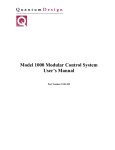
1
AD-4430B
DIN Rail Weighing Module
3.
External Dimensions
5.3.
Unit : mm
Simplified Instruction Manual
35.3
(2.5)
100
1.3
20°
28
Status Indicator
LED
Gross :
Meaning
LED lights when indicating gross value.
Net :
LED lights when indicating net value.
Hold :
LED lights when the hold function operates.
Stable :
LED lights when the current weighing value is stable.
Zero :
LED lights when the weighing value is center zero.
This LED works by selected function at
39.4
5.4.
5.5 34.5
110
Operation
4.
This manual describes how the product works and how to get the most
out of it in terms of performance. Read this manual thoroughly before
using the product and keep it at hand for future reference.
Refer to the instruction manual on the A&D home page.
URL: http://www.aandd.co.jp/
the part of the manufacturer to notify of changes.
This manual is subject to change without notice at any time to improve
Voltage requirement
Power requirement
Sensor power supply
Operating conditions
External dimensions
Mass
DC 24 V +10%, -15%
Approximately 6 W
5V 350 Ω sensor. Up to four sensors can be connected.
-10 °C to +50 °C, Max 85 %RH (no condensation)
35.3 × 110.0 × 101.3 mm (W×H×D)
Approximately 180 g
5. Panels
Step 1 When turning off the display, press and hold the
key and press the
key ( +
key).
of calibration mode is displayed.
Then
+
key to enter calibration mode.
is displayed. When returning to
weighing mode, press the
key.
5.1. Monitor
the A&D Company, limited.
5.3. Status Indicator
5.4. Keys
All rights reserved.
+
Proceeds to calibration in standby (OFF mode).
Power Supply Connector
5.6. Sensor Terminals
Of Load Cell
Cautions
2.1. Installation and Precautions
Guide for rail
The module complies class A computing device pursuant to Subpart J of Part 15
of FCC rules. (FCC = Federal Communications Commission in the U.S.A.)
The module complies the statutory EMC (Electromagnetic Compatibility)
directive 2004/108/EC and the Low Voltage Directive 2006/95/EC for safety of
electrical equipment designed for certain voltages for European Directives.
The module is a precision electronic instrument. Handle it carefully.
Avoid vibration, shock, extremely high temperature and humidity, direct sunlight,
dust, splashing water and air containing salt or sulfurous gases.
Avoid places where inflammable gases or vapors are present.
The operating temperature is -10°C to +50°C (14°F to 122°F).
Ground the module and DIN rail.
Keep cables away from power cables and other sources of electrical noise.
Use a stable DC24 V power source that does not include step down voltage
and noise.
Do not share the earth ground line and power line with other electrical power
equipment.
When extending the load cell cable, separate it from the power cable and
electrical cables with much noise.
Do not turn on the module until installation is complete. The module is not
equipped with a switch to turn off.
Use a shielded load cell cable.
Do not connect more sensors than the allowable number noted in the
specifications.
5.7. BCD Connector
5.5. Power Supply
Connector
Hook for rail
Vent
5.1. Monitor
Sensor Terminals Of Load Cell
SIG- .............
SIG+ .............
EXC- ...........
SEN- ...........
SEN+ ...........
EXC+ ...........
SHLD ...........
5.7.
Pull down when removing.
6.1.2.
The (-) input terminal of signal that is outputted from load cell.
The (+) input terminal of signal that is outputted from load cell.
The (-) output terminal to load cell excitation voltage (-).
The (-) input terminal for sensing input (-).
The (+) input terminal for sensing input (+).
The (+) output terminal for load cell excitation voltage (+).
Connect shield of sensor cable.
When connecting and removing the cables, push the buttons with a driver etc.
We recommend use of pole crimp terminals for the tips of cables.
Ex. : Pole crimp terminal
Push buttons when connecting and
removing the cables.
The load cell cable
Accessory connector for power
supply terminal.
Cautions During Use
Push buttons when connecting and
removing the cables.
BCD Connector
Power line
-2-
Span
calibration
key
Example
key
Example
Place mass
LED
key
In measuring
key. Then
is
Step 8 Press the
displayed and calibration data is stored in the
FRAM of the AD-4430B.
Step 9 Press the
6.2.
Display
key to return to weighing mode.
)
+
)
The voltage in zero
calibration is too small.
Calibration mode
(When display is turned off,
+
The mode to calibrate zero point and span of the AD-4430B using span mass.
)
Operation Mode
Function mode
(In weighing mode,
The condition of the AD-4430B can be updated and be stored.
Check mode
The mode to check the AD-4430B.
(In function mode,
+
Calibration
The AD-4430B measures the voltage of the sensor and displays it. Calibration mode
calibrates (adjusts) so as to measure and display correctly.
), minimum division (
) and weighing capacity
Specify decimal point (
) in function mode.
(
), the input voltage of span voltage
Adjust the input voltage of zero point (
(
) and mass corresponding to span voltage (
) in calibration mode.
The digital calibration can be performed in function mode.
-3-
Remove
mass
Key to store data
key
Calibration Errors
Cause
Resolution (Weighing
capacity / minimum division)
exceeds the limitation.
The voltage in zero
calibration is too large.
6.
LED
key
In measuring
is displayed, remove the mass
Step 7 When
from the weighing pan. When repeating span
key.
calibration, press the
The circuit of BCD is isolated from the
D.C. power supply and load cell
circuit.
Supply D.C. +24 V between BCD
PWR+24V terminal and COM
terminal.
5.8.
Zero
calibration
Span Calibration
Step 6 Place the mass on the weighing pan.
LED is lit and press the
Confirm that the
key. Then
is displayed for 2
seconds.
The monitor displays measurement data and settings with 7 segments and negative
sign. The decimal point is specified in function mode.
5.2. Connections
key
Step 5 When
is displayed, press the
key. The current span mass is displayed. A
figure for the mass flashes. Specify a new value
and
keys.
for the mass using the
When canceling span calibration and returning
key twice.
to weighing mode, press the
Cautions when wiring the power cables
Turn off all of the power supplies of devices related to the AD-4430B. Separate the
power cable of the AD-4430B from other power cables and cables with electrical noise.
5.6.
Vent
-1-
Proceeds to check mode in the function mode.
Calibration
mode
Zero Calibration
Step 4 Place nothing on the weighing pan.
LED is lit and press the
Confirm that the
key. Then
is displayed for 2
seconds. When canceling span calibration and
returning to weighing mode, press the
key twice.
+24 V ............ D.C. Power Supply +24 V terminal.
0 V ................ D.C. Power Supply 0 V terminal.
or translated into another language without the prior written consent of
The AD-4430B is a precision instrument that measures microvolt output from
sensors. Prevent noise sources such as power lines, radios, electric welders or
motors from affecting the instrument.
Do not disassemble the AD-4430B.
In all hold modes, the hold data is saved digitally, so there is no drooping of the
value displayed on the display panel or the analog output. Note that the hold
function is disabled when the AD-4430B is disconnected from the power supply.
6.1.1.
key
Step 3 Press the
key to display
.
When skipping zero calibration, press the
key and proceed to step 5.
Proceeds to function mode in weighing mode.
+
key
Step 2 Press the
Function key can be selected the function and use in weighing mode.
The return key or "the escape key" in setting mode.
5.5.
the product. No part of this manual may be photocopied, reproduced,
2.2.
Function
The display switch between gross and net in factory setting.
Press the key to turn on the display in standby (OFF mode).
Press and hold the key to turn off the display in weighing mode.
In the setting mode, this key to store new settings. "the enter key".
General Specifications
Product specifications are subject to change without any obligation on
2.
.
"The tare key" that displays zero for net weighing.
The key to select parameter or increase number in setting mode..
This Manual
Span Calibration using Mass
Preset a unit, decimal point, minimum division and weighing capacity in function
mode. The span calibration is performed using mass of the weighing capacity.
When
and a number are displayed, an error has occurred. Refer to
"Calibration Errors" for details.
The flashing decimal point means "no weighing value".
Before the calibration, turn on the AD4430B more than 10 minutes so as to
avoid temperature drift (change).
"The zero key" to perform the zero adjustment in weighing mode.
The key to change a selected item or move a flashed figure.
1WMPD4002677
2013
6.1.
Keys
36.1
1.1.
Perform stable measurement in the calibration to prevent measurement error.
During a stable measurement, the
LED lights.
The decimal point flashes in calibration mode.
Mass value exceeds the
weighing capacity.
Mass value is too light for
calibration.
Sensitivity of the load cell is
too small.
The polarity of the load cell
output is reversed.
The output of the weighing
capacity is out of range.
Treatment
Make the minimum division greater or make the
weighing capacity smaller. The specified value
depends on specifications of the weighing system.
Check the load cell rating and connection. When
nothing is wrong with the rating and connection,
adjust the load cell output. When the load cell or
A/D converter may be the cause of error, confirm
this by using the check mode.
Use an appropriate calibration weight and
calibrate again.
Use a load cell with higher sensitivity or make
the minimum division greater.
Check the load cell connection.
Use a load cell with a greater rating or make the
weighing capacity smaller.
-4-
6.3. Digital Linearization (
7.2.
)
Digital linearization is the non-linearity compensation function that can rectify or
reduce linearity deviation between zero point and weighing capacity.
Up to four points can be specified except zero. (Refer to
)
<
<
<
<
Relationship of points : Zero =
The high-order correction curve is used so that zero point and individual points
are arranged in a straight line.
Digital linearization includes span calibration.
When
and a number are displayed, an error has occurred. Refer to
"Calibration Error" for details.
A flashing decimal point means "no weighing value".
Before calibration, turn on the AD4430B more than 10 minutes so as to avoid
temperature drift (change).
Step 1 When turning off the display, press and hold
key and press the
key (
+
the
key). Then
of calibration mode
is displayed. Press the
key to display
.
Step 2 Press the
key to select
press the
key to enter digital
linearization.
Step 3
key
Step 6 Place the mass on the pan.
LED is displayed,
While
press the
key to store
the weighing value.
is displayed
Then
for 2 seconds.
Step 8
Step 9
Step 10
P
Input No.
key
Example
key
At each point,
perform the
same
operation and
measurement.
Example
In measuring
7.3.
7.3.1.
Item
Range
is displayed. Repeat the same
operation as Step 5 and Step 6 at the third
point.
is displayed. Repeat the same
operation as Step 5 and Step 6 at the fourth
point.
is displayed. Press the
key
to store new parameters into FRAM and
display
.
Input No.
The same as step 5,6
Input No.
The same as step 5,6
Input No.
The same as step 5,6
Key to store data
1 to 99999
0 to 100
0.0 to 5.0
0.0 to 9.9
0 to 9
0 to 1
0 to 1
key
Remove
mass
0 to 1
Step 11 Press the
key to return to weighing mode.
Remove all of mass from the pan.
1 to 3
1 to 2
7.
Function Mode (Function List)
The function mode stores parameters to control the weighing module.
The parameters are stored even without power supplied.
7.1. Outline
Types of Functions
............Calibration
............Linearity
.............Basics
............Hold function
............BCD output
The input voltage of the zero point (
), the span input voltage (
),
mass for span input voltage (
) are revised in calibration mode.
The decimal point flashes in function mode.
If pressing the
key while displaying the digital filter (
), the current
weighing value can be monitored. Press the
key again to return function
mode.
0 to 1
0 to 1
Item Name
Descriptions
Decimal point position of value.
0 0.0 0.00
0.000
0.0000
Minimum division of value.
1
2
5
10
20
50
Measurement can be displayed up to +8 digits
Weighing capacity
70000
(8 scales) from capacity. Decimal point
(Max. measurement)
D
depends on
.
Zero adjustment The range that the
key (zero key) works.
2
range
Deviation from the calibrated zero point [%].
D
0.0
Zero tracking time Used with
for zero tracking [sec.]
D
0.0
Zero tracking band Used with
for zero tracking [digit]
D
Stability detection
1.0
Used with
for stability detection [sec.]
time
D
Stability detection
2
Used with
for stability detection [digit]
band
P
The adjustment when value is unstable.
Tare and zero
1
adjustment when 0: Disables both functions.
P
1: Enables both functions.
unstable
Tare when the Tare when the gross weight is negative.
1
gross weight is 0: Disables tare.
P
negative
1: Enables tare.
Serial output when overflow and unstable.
Output when
1
0: Disables output.
overflow and
P
1: Enables output.
unstable
Judgment when the negative gross is exceeded.
Exceeding negative 1: Gross < -99999
1
gross weight
2: Gross < -capacity
P
3: Gross < -19 digit
Exceeding negative Judgment when the negative net is exceeded.
1
net weight
1: Gross < -99999 2: Gross < -Capacity
P
Clear the zero Select to clear the zero value.
1
value
0: Disable
1: Enable
P
Zero setting when When turning power on,
0
power is turned on 0: Disable
1: Enable
P
Input voltage at
zero
0.0001 to
9.9999
Input voltage at
span
Calibration weight
1 to 99999 corresponding to
input voltage at span
Gravity acceleration
9.7500 to
of place of
9.8500
calibration
9.7500 to
9.8500
Input voltage of the zero point [mV/V]
0.0000
D
Input voltage of the full scale [mV/V]
3.2000
D
32000
D
Gravity acceleration of the place where
2
calibrating the module. [m/s ]
9.8000
D
Disable averaging When turning on, the zero operation.
hold
0: Enable
1: Disable
-6-
Default
Type
0
P
Descriptions
Number of input Number of adjustment point. If 0, 1 or 2 is
points
selected, digital linearization is not used.
0.0000
D
Input voltage for linear-zero input. [mV/V]
The mass value for linear 1 input.
Decimal point depends on
.
0
D
The span voltage between linear-zero and linear 0.0000
1 input. [mV/V]
D
The mass value for linear 2 input.
Decimal point depends on
.
0
D
The span voltage between linear-zero and linear 0.0000
2 input. [mV/V]
D
The mass value for linear 3 input.
Decimal point depends on
.
0
D
Linear 3
0.0000 to
9.9999 Span voltage
Linear 4
0 to 99999 Mass value
The mass value for linear 4 input (Full scale).
Decimal point depends on
.
Linear 4
0.0000 to
9.9999 Span voltage
The span voltage between linear-zero and linear 0.0000
4 input (Full scale). [mV/V]
D
7.3.3.
Item
Range
0000
to 1111
0 to 7
1 to 3
0 to 9
0 to 16
1 to 3
-99999 to
99999
1 to 2
Mass value to equivalent to span input
voltage. (
) Decimal point depends on
.
Gravity acceleration Gravity acceleration of the place where using
2
of place of use the module. [m/s ]
Item Name
Linear 2
0.0000 to
9.9999 Span voltage
Linear 3
0 to 99999 Mass value
Default
Type
0
P
1
P
7.3.4.
) Of The Select Mode
Linear 1
0.0000 to
9.9999 Span voltage
Linear 2
0 to 99999 Mass value
) Of Select Mode
-7.0000 to
7.0000
0 to 1
-5-
Calibration (
Linearity (
7.0000 to Linear-zero
7.0000
Linear 1
0 to 99999 Mass value
Types and Items
Decimal point
0 to 0.0000
position
Minimum division
1 to 50
(A scale / digit)
0.0 to 9.9
is displayed. Repeat the same
operation as Step 5 and Step 6 at the
second point.
1 to 4
Parameters Selection And Digital Parameters
Place mass
LED Stable
key
Item
Range
The type to change value ( figure flashing )
..........Moves the flashing figure.
..........Changes the value of the flashing figure.
.......Activates (store) value and returns to select mode.
.......Deactivates value and returns to select mode.
Digital
linearization
LED Stable
key
In measuring
7.3.2.
Type of parameter selection ( all figures flashing)
..........Selects a parameter.
.......Activates (store) parameter and returns to select mode.
.......Deactivates parameter and returns to select mode.
D
Zero point
of the zero point is displayed.
Step 5 When displaying
,
press the
key to select
a mass value. Specify it using
and
key.
the
Step 7
key
and
Step 4 Place nothing on the pan.
While
LED is displayed, press the
key to store the weighing value.
is displayed for 2 seconds.
Then
7.2.2.
key
key
Operation
7.2.1.
Select Modes Under Function Mode
..............Selects a type of select mode (3 upper figures)
..........Enters a selected mode.
..............Selects an item under the selected mode (2 lower figures)
..........Enters the item.
..........Stores parameters and returns to weighing mode.
Basics (
The span voltage between linear-zero and linear 0.0000
3 input. [mV/V]
D
0
D
) Of The Select Mode
Item Name
Disable key
switchs
key
Descriptions
Figure corresponds to each key (switch).
These are enabled at weighing mode.
Figure
4 fig.
3 fig.
2 fig.
1 fig.
Parameter 0: Enable
1: Disable
0: None
4: Momentary switch
1: Print command
5: Display exchange
2: Hold
6: Tare clear
3: Alternative switch 7: Zero clear
(depends on
Set value of
near-zero
The reference value for near-zero.
.
Decimal point depends on
Mass to be compared
1: Gross weight
with near-zero
2: Net weight
Time to wait before commencing hold or
averaging. [sec.]
0.00
D
0 to 2
0 to1
0.00
to 9.99
0 to 99999
0 to 1
7.3.5.
Condition of
automatic
start
Release due
to falling
control input
1 to2
Output logic of
data transfer
Output logic of
negative sign
Output logic
of status
Output logic
of strobe
0 to5
Input
selection
0 to 12
Output
selection
1 to2
0
P
15
P
1
P
1 to2
Release when control input is falling.
0: Do not release
1: Release
1
P
Release when fluctuation from the holding
value exceeds a set value. Decimal point
depends on
. 0 : Continue
Release when the weighing value is in the
near-zero range.
0: Do not release.
1: Release.
Item Name
)
0
P
Release due
to range of
fluctuation
Release in
near-zero
range
BCD Output (
0
D
0
P
Default
Type
1: Weighing value 3: Net weight
1
2: Gross weight 4: Data specified at BCD input
P
1: Stream
3: Manual printing
1
2: Automatic printing
P
5 times/sec.
10 times/sec.
(Depends on
)
20
20 times/sec.
P
100 times/sec.
1000 times/sec.
2
1: Positive logic
2: Negative logic
P
2
1: Positive logic
2: Negative logic
P
2
1: Positive logic
2: Negative logic
P
2
1: Positive logic
2: Negative logic
P
0: None
1: Clear zero
2: Clear tare
3
3: Changing between gross and net
P
4: Print command
5:
key
0: None
1: Stabilization
2: During tare
3: Zero band
4: Hold busy state
5: HI output (Over upper limit)
1
6: OK output (Within upper and lower limits)
P
7: LO output (Under lower limit)
8: During operating weighing (On)
9: During operating weighing (1 Hz)
10: During operating weighing (50 Hz)
11: Alarm (Zero correction error and tare error)
key
12: Busy
Descriptions
1
P
-99999 to
99999
0.00
D
) Of The Select Mode
10
D
-10
D
Default
Type
Condition for starting the hold or averaging.
0: Not used
2: Above the near-zero range
1: Above the near-zero range, and stable
Release after a set amount of time has
passed. [ sec.] 0.00 : Continue
Item
Range
1 to2
Descriptions
Time release
Data transfer
rate
Reference value for the lower limit.
.
Decimal point depends on
-7-
Start wait
time
5 to 1000
Set value of
lower limit
1 to 2
0.00
to 9.99
0000
2 進数
D
10
D
0
P
0.00
D
Data transfer
mode
Reference value for the upper limit.
Decimal point depends on
.
Mass to be compared
1: Gross weight
2: Net weight
with upper & lower limit
Output logic of upper The logic of the comparator function output.
and lower limit
1: Positive logic
2: Negative logic
Time to calculate the average. [sec.]
0.00 : Not used
1 to3
Set value of
upper limit
1 to 2
Average
time
Output data
-99999 to
99999
9.8000
D
0.00
to 9.99
1 to4
20
P
) Of The Select Mode
Item Name
Default
Type
5
P
Display update
1: 20 times/s
2: 10 times/s
3: 5 times/s
rate
0: None
1: Zero tracking in progress
2: Alarm (Zero range setting error, over)
key status
3:
4: Zero band
display
5: HI output (Over the upper limit value)
6: OK output (Between upper and lower limit values)
7: LO output (Below the lower limit value)
8: User input 1
9: User output 1
Selects a cutoff frequency.
0: None
6: 20.0 Hz
12: 2.8 Hz
1: 100.0 Hz
7: 14.0 Hz
13: 2.0 Hz
Low pass digital
2: 70.0 Hz
8: 10.0 Hz
14: 1.4 Hz
filter
3: 56.0 Hz
9: 7.0 Hz
15: 1.0 Hz
4: 40.0 Hz
10: 5.6 Hz
16: 0.7 Hz
5: 28.0 Hz
11: 4.0 Hz
1: Hold immediately
Hold
2: Peak hold
3: Averaging hold
Hold Function (
Item
Range
3-23-14 Higashi-Ikebukuro, Toshima-ku, Tokyo 170-0013, JAPAN
Telephone: [81] (3) 5391-6132
Fax: [81] (3) 5391-6148
1
P
1
P
-8-