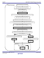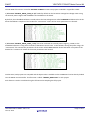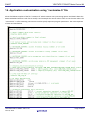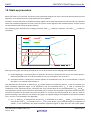
1
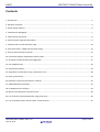
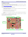
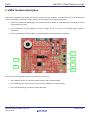
USER MANUAL YROTATE-IT-RX62T Low Cost Motor Control Kit based on RX62T UM-YROTATE-IT-RX62T Rev.1.00 Jan 15, 2014 Introduction The Renesas Motor Control Kit, YROTATE-IT-RX62T, is based on the RX62T device from the powerful 32-bit RX microcontroller family. The kit enables engineers to easily test and evaluate the performance of the RX62T in a laboratory environment when driving any 3-phase Permanent Magnet Synchronous Motor (e.g. AC Brushless Motor) using an advanced sensorless Field Oriented Control algorithm. Typical applications for this type of solution are compressors, air conditioning, fans, air extractors, pumps and industrial drives. The phase current measurement is done via three shunts which offers a low cost solution, avoiding the need for an expensive current sensor. A single shunt current reading method is also available. The powerful user-friendly PC Graphical User Interface (GUI) gives real time access to key motor performance parameters and provides a unique motor auto-tuning facility. The hardware is designed for easy access to key system test points and for the ability to hook up to an RX62T debugger. Although the board is normally powered directly from the USB port of a Host PC, connectors are provided to utilise external power supplies where required. The YROTATE-IT-RX62T is an ideal tool to check out all the key performance parameters of your selected motor, before embarking on a final end application system design. Target Device: RX62T/63T Microcontroller Series UM-YROTATE-IT-RX62T Rev.1.00 Jan 15, 2014 Page 1 of 51 RX62T YROTATE-IT-RX62T Motor Control Kit Contents 1. Key features .................................................................................................................................................................. 3 2. Hardware overview ....................................................................................................................................................... 4 3. Power supply selection ................................................................................................................................................. 6 4. Test points for debugging.............................................................................................................................................. 7 5. LEDs function description ............................................................................................................................................. 8 6. Internal power stage brief description ......................................................................................................................... 9 7. Interface with an external power stage ...................................................................................................................... 10 8. Connection with a 1.5KW external power stage ........................................................................................................ 14 9. Control microcontroller overview ............................................................................................................................... 15 10. Permanent magnets AC Brushless motor model ...................................................................................................... 17 11. Sensorless Field Oriented Control Algorithm............................................................................................................ 22 12. Flux Feedback Gain ................................................................................................................................................... 23 13. Software description ................................................................................................................................................. 24 14. Application customization using “customize.h” file ................................................................................................. 28 15. Start-up procedure.................................................................................................................................................... 30 16. Reference system transformations in details ........................................................................................................... 32 17. PWM modulation technique ..................................................................................................................................... 33 18. PC Graphical User Interface ...................................................................................................................................... 34 19. Motor Auto-calibration using the PC GUI ................................................................................................................. 36 20. List of motors tuned automatically using the PC GUI ............................................................................................... 46 21. List of variables used in the file name: “motorcontrol.c” ......................................................................................... 47 UM-YROTATE-IT-RX62T Rev.1.00 Jan 15, 2014 Page 2 of 51 RX62T YROTATE-IT-RX62T Motor Control Kit 1. Key features UM-YROTATE-IT-RX62T Rev.1.00 Jan 15, 2014 Page 3 of 51 RX62T YROTATE-IT-RX62T Motor Control Kit 2. Hardware overview The Motor Control kit is a single board inverter, based on the new RX series microcontroller RX62T. The hardware includes a low-voltage MOSFETs power stage, and a communication stage. The ordering part name of the kit is: YROTATE-IT-RX62T. The latest updates of the kit material are available on the webpage: http://tinyurl.com/YROTATE-IT-RX62T To obtain the maximum flexibility, the reference board includes: • A complete 3-phase inverter on-board with a low voltage motor, so it becomes easy to test the powerful sensorless algorithm on the RX62T • USB communication with the PC via a H8S2212 microcontroller • Connectors for hall sensors and encoder connections • Compatibility with the existing Motor Control Reference Platforms MCRP05/06 power stage available at Renesas. To achieve these aims, an independent communication stage was implemented, based on the Renesas microcontroller H8S2212, which performs the USB to serial conversion. The two serial lines RX and TX are fully insulated Signals conditioning POWER STAGE STEP-DOWN STEP_UP EXTERNAL POWER STAGE INTERFACE CONTROL STAGE UM-YROTATE-IT-RX62T Rev.1.00 Jan 15, 2014 HALL, ENCODER ISOLATION COMMUNICATION Page 4 of 51 RX62T YROTATE-IT-RX62T Motor Control Kit This stage uses the PC USB power lines as power supply. Furthermore, the possibility to supply all the board using the PC USB port was added, realizing a step-up converter to obtain the inverter VBUS necessary for the motor; obviously, if this feature is used, the system is no more insulated from the PC. If external power supply is used for the inverter, the logic power supply is obtained through a step-down converter, in order to reduce heating and power consumption. Please refer to the electrical drawings or schematics to get the hardware implementation in more details. UM-YROTATE-IT-RX62T Rev.1.00 Jan 15, 2014 Page 5 of 51 RX62T YROTATE-IT-RX62T Motor Control Kit 3. Power supply selection As stated before, there are two ways to supply power to the board. One possibility is to use directly the PC USB supply, and in this case the current you can give to the motor is limited by the USB possibilities. A dual power USB cable is recommended to give enough power to the board. The second possibility is to use an external voltage DC source to supply the board. The recommended voltage values are between 12VDC and 24VDC. In this case the communication stage is insulated from the inverter. The selection between the two possibilities is made through three jumpers in the J2 connector, as described in the following figure. 9 4 1 9 4 1 8 5 2 8 5 2 7 6 3 7 6 3 PC USB SUPPLY SELECTION EXTERNAL SUPPLY SELECTION The first jumper configuration connects the USB ground to the inverter ground, the USB 5Vdc to the logic +5Vdc and the output of the step-up converter (around 13Vdc) to the inverter DC link. The second jumper configuration connects the external power supply ground to the inverter ground, the output of the step-down converter (+5Vdc) to the logic +5Vdc and the external +Vdc (from 12 to 24 Vdc) to the inverter DC link. UM-YROTATE-IT-RX62T Rev.1.00 Jan 15, 2014 Page 6 of 51 RX62T YROTATE-IT-RX62T Motor Control Kit 4. Test points for debugging Several specific test points are available on the board to visualize with the oscilloscope the behavior of some internal analog signals. it is very useful during the tuning process for adapting the software to a new motor to use the test points. There are specific 3 PWM debug test points; TP5, TP6 & TP7 as shown below. UM-YROTATE-IT-RX62T Rev.1.00 Jan 15, 2014 Page 7 of 51 RX62T YROTATE-IT-RX62T Motor Control Kit 5. LEDs function description Three LEDs available on the board are directly connected to the hardware and allows the user to understand the status of the supply of the board. Please refer to the LED map for the following indications: • DL8 is connected to the USB supply, so it indicates that the USB port is supplied (and, by consequence, all the communication section). • DL7 is connected to the step-down converter output, and it is on only if an external power supply is connected. • DL9 is connected to the logic supply, so it indicates that the control section is supplied. DL8 DL4 DL7 DL9 DL1 DL6 The other LEDs in the board are driven via software, in particular: • DL6 is blinking if there is a communication between the PC and the board. • DL1 is blinking if the control section microcontroller (RX62T) is running normally. • DL4 is quickly blinking if an alarm has been detected. UM-YROTATE-IT-RX62T Rev.1.00 Jan 15, 2014 Page 8 of 51 RX62T YROTATE-IT-RX62T Motor Control Kit 6. Internal power stage brief description The power stage is a complete 3-phase bridge composed with discrete low voltage power MOSFETs, mounted on the bottom side of the board. The MOSFETs are the Renesas RJK0654DPB n-channel power MOSFETs (please refer to the data-sheet for the characteristics). On the upper side of the board is mounted the MOSFETs driving circuit, composed with discrete elements (refer to the electric drawings). 3 PHASES BRIDGE CURRENT READING SHUNTS The current reading shunts are also in the bottom side of the board, while the signal conditioning circuit is in the upper side. The inverter has the classical schema with the three shunts on the lower arms: UM-YROTATE-IT-RX62T Rev.1.00 Jan 15, 2014 Page 9 of 51 RX62T YROTATE-IT-RX62T Motor Control Kit 7. Interface with an external power stage Since internal power stage allows only the management of small motors, an interface with an external power stage was added to the PCB. This was made easy due to the presence in the microcontroller of several timer sections that make it possible to manage up to two 3-phase Brushless AC motors at the same time. Please find below the schematics of the connectors present in the board, used for connecting an external power stage. CONN. J12 JUMPER JP5 VBUS-EXT 1 2 2 1 3 4 4 3 5 6 7 8 9 10 11 12 13 14 15 16 +5V CONN. J11 MTIOC3D (UP53) PHASE U LOWER PWM DRIVE SIGNAL 1 2 MTIOC4C (UP52) PHASE V LOWER PWM DRIVE SIGNAL 3 4 MTIOC4D (UP51) PHASE W LOWER PWM DRIVE SIGNAL 5 6 MTIOC3B (UP56) PHASE U UPPER PWM DRIVE SIGNAL 7 8 MTIOC4A (UP55) PHASE V UPPER PWM DRIVE SIGNAL 9 10 MTIOC4B (UP54) PHASE W UPPER PWM DRIVE SIGNAL 11 12 13 14 15 16 POE0 (UP57) HARDWARE ALARM SIGNAL 100R 10N NM +5V UM-YROTATE-IT-RX62T Rev.1.00 Jan 15, 2014 Page 10 of 51 RX62T YROTATE-IT-RX62T Motor Control Kit AN103 (UP84) VBUS VOLTAGE SIGNAL AN101 (UP86) V PHASE CURRENT SIGNAL AN102 (UP85) U PHASE CURRENT SIGNAL 100R 100R 1N 100R 1N 1N +5V +5V +5V MTIC5U (UP96) U PHASE COMM. SIGNAL 1K 15K +5V MTIC5V (UP97) V PHASE COMM. SIGNAL 1K 1 2 3 4 5 6 7 8 9 10 11 12 13 14 15 16 17 18 19 20 15K +5V MTIC5W (UP98) W PHASE COMM. SIGNAL 1K 21 22 23 24 25 26 AN100 (UP87) W PHASE CURRENT SIGNAL 100R 15K CONN. J13 +5V 1N +5V AN2 (UP75) THERMAL SENSOR SIGNAL 1K 10K 10K +5V 100N +5V The interface between the board and an external power stage is organized as follows: a) A 16 pins connector (J11) is used for the PWM drive signals; the signals are directly connected to the microcontroller output pins, and there is no pull-up or pull-down resistor connected, so the polarization has to be done in the power stage (note that in case of alarm, the microcontroller output pins can be placed in high impedance state, so the external polarization is necessary); these output commands are logic level signals, with limited current output capability, so an external driver is probably required. A further line is connected to the microcontroller: it is the external alarm signal, connected to the POE input pin; this pin is not polarized, so if the POE is enabled and the input is left unconnected, undesired alarms can occur. All the free pins of the connector are connected to the board ground to minimize the cross talking of the lines if a flat cable is used. b) A 26 pins connector (J13) is used to collect some signals from the power stage, in particular the current readings and the DC link voltage reading; those signals are clamped and weakly filtered, then directly connected to the A/D converter input pins of the microcontroller, so the external power stage has to take care of the gain and the offset of these signals. An input is dedicated also to a thermal sensor, and a pull-up resistor is present. Three further signals are managed: they are the commutation signals from the output phases, useful if the hardware compensation of dead-times facility of the MTU is used; those signals are UM-YROTATE-IT-RX62T Rev.1.00 Jan 15, 2014 Page 11 of 51 RX62T YROTATE-IT-RX62T Motor Control Kit clamped with a diode directly connected with the microcontroller power supply, so a suitable series resistance is needed in the power stage to avoid damages to the board. c) A further connector (J12) can be used to supply the board from the power stage or vice-versa (making a short circuit between the pins 1 and 2 of the jumper JP5); also the board 5V can be made available to the power board (making a short circuit between the pins 3 and 4 of JP5), but not vice-versa, because they are directly connected to the step-down switching supply of the board. The ground connection is always on, and it represents the reference for all the interface signals. In the next figure a simple example regarding how the power board has to be arranged is presented: the power supply comes from the supply connector, and the supply for power module is derived from it. The external supply is also used to supply the microcontroller board through the connector J12A (and the jumper JP5 in microcontroller board); the 5V supply for current sensors and for the signal polarization is derived from the microcontroller board, through J12A (and JP5). The PWM drive signals are taken from J11A, while the current sensing signals and the bus voltage measurement are brought to J13A (the phase commutation signals and the temperature sensing signal are not reported for sake of simplicity). Please refer to the complete schematics for further details. UM-YROTATE-IT-RX62T Rev.1.00 Jan 15, 2014 Page 12 of 51 RX62T UM-YROTATE-IT-RX62T Rev.1.00 Jan 15, 2014 YROTATE-IT-RX62T Motor Control Kit Page 13 of 51 RX62T YROTATE-IT-RX62T Motor Control Kit 8. Connection with a 1.5KW external power stage The interface for an external power supply was designed to be compatible with the power stages of previous Renesas motor control platforms MCRP05/06. So it becomes possible to use the same power stage and connect any Motor Control board using RX62T, RL78/G14 or RX220 microcontroller families. The schematics of a 1.5KW power stage are included into the documentation on the CD-ROM delivered with the Kit. Please find below the details to connect the power stage to the RX62T motor control kit. JP2 MOTOR CONNECTOR JP5 DC BUS CONNECTOR POWER SUPPLY CONNECTOR J12 J11 J13 The power supply of 24VDC is delivered by the 1.5KW power board (on the left hand side). It’s directly connected to the RX62T control board thanks to the Jumper JP5 (on the right hand side). The pin 1 and 2 of the jumper JP5 are short-circuited, while the pin 3 and 4 are left open. In the microcontroller board, the supply configuration jumper JP2 is configured in order to select the external supply (not the USB one). In the power stage board, a DC bus connector allows the user to provide a higher external DC voltage; in such way high voltage motors can be managed. UM-YROTATE-IT-RX62T Rev.1.00 Jan 15, 2014 Page 14 of 51 RX62T YROTATE-IT-RX62T Motor Control Kit 9. Control microcontroller overview The RX62T/63T Group is a set of microcontrollers featuring the high-speed, high-performance RX CPU as the 100MHz processor core. Each basic instruction of the processor is executable in one cycle of the system clock. Calculation functionality is enhanced by the inclusion of a single-precision floating-point calculation unit as well as a 32-bit multiplier and divider. Additionally, code efficiency is improved by instructions with lengths that are variable in byte units to cover an enhanced range of addressing modes. A multi-functional timer pulse unit 3 (for motor control), general PWM timer, compare match timers, watchdog timer, independent watchdog timer, serial communications interfaces, I2C bus interfaces, CAN module, serial peripheral interface, LIN module, 12-bit A/D converters with three-channel simultaneous sampling function, and 10bit A/D converter are incorporated as peripheral functions which are essential to motor control devices. In addition, the 12-bit A/D converters include a window comparator and programmable gain amplifier for additional functionality. Please find below the summary of the RX62T features: RX600 CPU High-speed: 100MHz clock High performance: 1.65MIPS/MHz Low current consumption: only 50mA @ 100MHz Single-precision floating point unit FPU, barrel shifter, MAC, RMPA 256kB Flash/16kB RAM to 64kB Flash/8kB RAM Zero wait access to Flash memory 64pin – 112pin package options Functions Enhanced PWM resolution with MTU3, enhanced PWM functionality with GPT 12-bit A/D converter (1µs) : 4 channels x 2 unit , 10-bit A/D converter (1µs) : 12 channels x 1 unit Three S/H circuits for each unit: Three shunts control enable Double data registers for each unit: 1 shunt control enable Programmable gain Operational amplifier, Window comparator for Voltage monitoring CAN option UM-YROTATE-IT-RX62T Rev.1.00 Jan 15, 2014 Page 15 of 51 RX62T YROTATE-IT-RX62T Motor Control Kit Large-capacity flash memory units capable of high-speed operation are included as on-chip memory, significantly reducing the cost of configuring systems. The main application fields of this microcontroller are: industrial equipment, household electrical appliances, machines requiring motor control, and inverter-powered machines. Please find below the block diagram of the RX62T and the role of each peripherals. RX CPU 100MHz 2.7~3.6V (4.0-5.5V) Flash Data Flash 8KB FPU Multiplier-divider and multiplier-accumulator I/O ports SCI x 3 ch SPI x 1ch POR/LVD I C x 1 ch RCAN x 1ch 16-bit timer x 4 ch (CMT) GPT 1ph, PWM with dead time Inverter control,PFC etc 1ph, PWM with dead time Inverter control,PFC etc 1ph, PWM with dead time Inverter control,PFC etc 1ph, PWM with dead time Inverter control,PFC etc Protection - External input (POE) -Clock stop detection -Clock monitoring 6 OpAmp 6 comp Serial communication 2 CRC Maximum current & VBUS management RAM Self diagnostic 12bit AD 4ch OCO (Low speed) DTC MTU3 IPM 3ph. PWM with dead time (Use two 16-bit timer ch3&4) 3ph. PWM with dead time (Use two 16-bit timer ch6&7) Hall sensor / BEMF Input (Use one 16-bit timer ch0) Dead time compensation (Use one 16-bit timer ch5) PMAC M M 1 or 2 Encoder Input (Use 1or2 16-bit timer ch1/2) 12bit AD 4ch Self diagnostic Watchdog timer x 2 ch (One of two includes the LOCO) fault Motor POE 10-bit ADC x 12ch Shunts reading UM-YROTATE-IT-RX62T Rev.1.00 Jan 15, 2014 Page 16 of 51 RX62T YROTATE-IT-RX62T Motor Control Kit 10. Permanent magnets AC Brushless motor model The synchronous permanent magnets motor (e.g. sinusoidal Brushless motor) is widely used in the industry. More and more home appliance makers are now using such AC Brushless motor, mainly because of the intrinsic motor efficiency. The permanent magnet motor is made with few components: 1. A stator formed by stacking sheared metal plates where internally the copper wiring is wound, constructing the stator winding 2. A rotor in which permanent magnets are fixed 3. Two covers with ball bearings that keep together the stator and the rotor; the rotor is free to rotate inside the stator “a” winding “b” winding ia Motor axis (shaft) + va “a” winding magnetic axis vb ic ib “c” winding + vc + How current flows into “a” winding The working principle is quite simple: if we supply the motor with a three-phase system of sinusoidal voltages, at constant frequency, in the stator windings flow sinusoidal currents, which create a rotating magnetic field. The permanent magnets in the rotor tend to stay aligned with the rotating field, so the rotor rotates at synchronous speed. The main challenge in driving this type of motor is to know the rotor position in real-time, so mainly implementation are using a position sensor or a speed sensor. In our implementation, the system is using either one or three shunts to detect the rotor position in real-time. Let’s analyse the motor from a mathematic point of view. If we apply three voltages va(t), vb(t), vc(t) to the stator windings, the relations between phase voltages and currents are: UM-YROTATE-IT-RX62T Rev.1.00 Jan 15, 2014 Page 17 of 51 RX62T YROTATE-IT-RX62T Motor Control Kit dλ a dt dλ vb = RS ib + b dt dλ vc = RS ic + c dt v a = R S ia + - λi is the magnetic flux linkage with the i-th stator winding - RS is the stator phase resistance (the resistance of one of the stator windings) The magnetic flux linkages λi are composed by two items, one due to the stator currents, one to the permanent magnets. β axis c axis a α c’ b’ a axis c Λm β’ ϑ β’ α axis b α’ a’ b axis Real axes (a, b, c) and equivalent ones (α, β); a fixed amplitude vector can be completely determined by its position respect the (α, β) system (angle ϑ) The permanent magnet creates a magnetic field that is constant in amplitude and fixed in position in respect to the rotor. This magnetic field can be represented by vector Λm whose position in respect to the stator is determined by the angle ϑ between the vector direction and the stator reference frame. The contribution of the permanent magnets in the flux linkages depends on the relative position of the rotor and the stator represented by the mechanical-electric angle ϑ. It is, in every axis, the projection of the constant flux vector Λm in the direction of the axis: λa = Lia + Λ m cos(ϑ ) λb = Lib + Λ m cos(ϑ − 2π 3 ) λc = Lic + Λ m cos(ϑ − 4π 3 ) UM-YROTATE-IT-RX62T Rev.1.00 Jan 15, 2014 Page 18 of 51 RX62T YROTATE-IT-RX62T Motor Control Kit Supposing that the rotor is rotating at constant speed ω (that is: ϑ(t) = ωt) the flux linkages derivatives can be calculated, and we obtain: dia − ωΛ m sin(ϑ ) dt di vb = RS ib + L b − ωΛ m sin(ϑ − 2π ) 3 dt di vc = RS ib + L b − ωΛ m sin(ϑ − 4π ) 3 dt v a = R S ia + L A “three phases system” may be represented by an equivalent “two phases system”. So the by using specific transformations, our three equations system is equivalent to a two equations system. It is basically a mathematical representation in a new reference coordinates system. In the two phases (α,β) fixed system the above equations become: vα = RS iα + vβ = RS iβ + dλα dt dλβ dt For the magnetic field equations, we got: λα = Liα + λαm = Liα + Λ m cos(ϑ ) λβ = Liβ + λβm = Liβ + Λ m sin(ϑ ) After performing the derivation: dλα di di = L α − ωΛ m sin(ϑ ) = L α − ωλ βm dt dt dt dλβ diβ diβ =L + ωΛ m cos(ϑ ) = L + ωλαm dt dt dt Finally, we obtain for the voltages in (α,β) system: diα − ωλ βm dt diβ vβ = RS iβ + L + ωλαm dt vα = RS iα + L A second reference frame is used to represent the equations as the frame is turning at the rotor speed. So the “d” axis is chosen in the direction of the magnetic vector Λm, and with the “q” axis orthogonal to the “d” axis. The new reference system is (d, q). UM-YROTATE-IT-RX62T Rev.1.00 Jan 15, 2014 Page 19 of 51 RX62T YROTATE-IT-RX62T Motor Control Kit The reference frame transformations from the (α,β) system to the (d, q) system depends on the instantaneous position angle ϑ So we obtain two inter-dependant equations in the (d, q) system: did − ωLiq dt diq vq = RS iq + L + ωLid + ωΛ m dt vd = RS id + L These two equations represent the mathematical motor model. Vd 1/(R+sL) + Id + Lω e pL τload Vq + 1/(R+sL) Iq (3/2)pΛ τ + 1/(B+sJ) ω mec Λω e pΛ A control algorithm which wants to produce determined currents in the (d, q) system must impose voltages given from the formulas above. This is ensured by closed loop PI control on both axis “d” & “q” (Proportional Integral). Since there is a mutual influence between the two axes, decoupling terms can be used. In the block scheme the mechanic part is included, where “p” is the number of pole pairs, while “B” represents friction, “J” the inertia, “τload“ the load torque and “τ” the motor torque. 3 2 τ = × p×Λ The angular speed ω is represented in the scheme as ωe to distinguish the electrical speed from the mechanical one. Let’s now consider the equations we have seen in (α,β) system: UM-YROTATE-IT-RX62T Rev.1.00 Jan 15, 2014 Page 20 of 51 RX62T YROTATE-IT-RX62T Motor Control Kit vα = RS iα + vβ = RS iβ + dλα dt dλβ dt These equations show that magnetic flux can be obtained from applied voltages and measured currents simply by integration: t λα = λα 0 + ∫ (vα −RS iα )dt 0 t λβ = λβ 0 + ∫ (vβ −RS iβ )d 0 Furthermore: Λ m cos(ϑ ) = λα − Liα Λ m sin(ϑ ) = λβ − Liβ If the synchronous inductance L is small, the current terms can be neglected, if not they have to be considered. In general: t x = Λ m cos(ϑ ) = λα − Liα = λα 0 + ∫ (vα −RS iα )dt − Liα 0 t y = Λ m sin(ϑ ) = λβ − Liβ = λβ 0 + ∫ (vβ −RS iβ )dt − Liβ 0 So in the (α,β) system phase we obtain from the flux components: ϑ = arctan( x y ) The system speed ω can be obtained as the derivative of the angle ϑ. ω= d ϑ (t ) dt Based on this, a sensorless control algorithm was developed to give the imposed phase voltages, to measure phase currents, to estimate the angular position ϑ and finally the system speed. UM-YROTATE-IT-RX62T Rev.1.00 Jan 15, 2014 Page 21 of 51 RX62T YROTATE-IT-RX62T Motor Control Kit 11. Sensorless Field Oriented Control Algorithm Please, find below the sensorless FOC algorithm block diagram. 0 [Idref] Id PI + Vd Vq Vα α β Vβ (d, q) → (α, β) (α, β) → (u, v, w) PWM Modulation Motor ωref Speed PI Iqref + + Current Reading (z-1) Iq PI z-1 z-1 z-1 z-1 - - z-1 ωest Speed estimation Idmea Iqmea ϑest (α, β) → (d, q) Flux Phase estimation Iα αmea Iβ β mea (u, v, w) → (α, β) Iumea Ivmea The only difference between the three shunts configuration and the single shunt one is in the “Current Reading” block, the rest of the algorithm remains the same. UM-YROTATE-IT-RX62T Rev.1.00 Jan 15, 2014 Page 22 of 51 RX62T YROTATE-IT-RX62T Motor Control Kit 12. Flux Feedback Gain The block scheme of the exact BEMF integration method for flux position estimation is the following: λe G e j ϑ v + + ∫ - λS * λm + ∠ ϑ * RS λm + - i LS λm The inputs of the system are the imposed voltage vector V and the measured current vector I. The motor phase resistance Rs, the synchronous inductance Ls and the permanent magnet flux amplitude λm are known as parameters and motor specific. The integral operation is corrected with a signal obtained modulating accordingly with the estimated phase the error between the estimated flux amplitude and the amplitude of the permanent magnets flux. The gain of this correction is indicated with G and it is this feedback which avoids the integral divergence due to the errors, offsets and so on. The higher G is, the higher is the correspondence between the estimated amplitude and the theoretical one, but the larger can be the induced phase error. The choice of G is a compromise, in order to guarantee that the integral remains close to its theoretical value, but free enough to estimate the correct system phase. UM-YROTATE-IT-RX62T Rev.1.00 Jan 15, 2014 Page 23 of 51 RX62T YROTATE-IT-RX62T Motor Control Kit 13. Software description The software of the YROTATE-IT-RX62T kit is working on the RX62T microcontroller clocked at 100MHz. It is a fast and powerful device for this class of algorithm. This allows the user to realize virtually what he wants in addition. The total software uses the following resources: 1) FLASH : 18Kbytes 2) RAM : 3Kbytes Please note that these data include also the communication interface and the reference board management. The following flowcharts show the software implementation of the motor control part of the software. Software organization Hardware and software Interrupt enabling 100µ µs Interrupt 10ms Main UM-YROTATE-IT-RX62T Rev.1.00 Jan 15, 2014 Page 24 of 51 RX62T YROTATE-IT-RX62T Motor Control Kit Main Program EEPROM parameters upload A/D channels offset reading Peripherals initialization Variables initialization Interrupt enabling Main loop synchronization cnt_int == 0 ? YES NO cnt_int = NUM_INT Main loop body Speed ramp management Communication management General board management Parameters modification management UM-YROTATE-IT-RX62T Rev.1.00 Jan 15, 2014 Page 25 of 51 RX62T YROTATE-IT-RX62T Motor Control Kit Control interrupt Phase currents (iumea, ivmea) reading Transformations (using the phase angle ϑ): (iumea, ivmea) → (iamea, ibmea) → (idmea, iqmea) Read DC Link voltage vbus Phase angle update: ϑ = ϑnew Current PI controls use (idref, iqref), (idmea,iqmea) to produce (vdout, vqout) Transformations (using the phase angle ϑ): (vdout, vqout) → (vaout, vbout) → (vuout, vvout) PWM output commands generation (using vuout, vvout) vbus is used to calculate maximum phase voltage (used in current PI controls) Phase estimation based on old_vaout, old_vbout, iamea, ibmea, produces new estimated phase angle ϑest Voltage memories update: old_vaout = vaout, old_vbout = vbout Speed estimation produces ωest Estimation errors detection (if errors an alarm is produced) YES NO Start-up in progress? Start-up procedure produces idref, iqref, ϑstup idref = 0 ϑnew = ϑstup Speed PI control uses (ωref, ωest) to obtain iqref ϑnew = ϑest Main loop synchronization cnt_int > 0 ? NO YES --cnt_int UM-YROTATE-IT-RX62T Rev.1.00 Jan 15, 2014 Page 26 of 51 RX62T YROTATE-IT-RX62T Motor Control Kit The CD-ROM of the motor control kit YROTATE-IT-RX62T contains two projects available in zipped files called: 1) File name: “MCRP07_RX62T_intPS_v7.zip” loaded by default on the kit PCB to manage low voltage motor using the internal power stage made of MOSFETs and available on the board. By default, the embedded software is tuned to drive the low voltage motor called: FL28BL38 and delivered in the kit. Please find below a snapshot of the header file “customize.h” where all the motor parameters are located. 2) File name: “MCRP07_RX62T_extPS_v7.zip” has to be used with an external power stage e.g. 1.5KW, as the embedded software is using other channels of the Motor control timer. In the software driving the power stage, the “customize.h” file contains the parameters of the motor called: MB057GA240. Please find below a snapshot of the header file “customize.h” where all the motor parameters are located: Furthermore, both projects are compiled and the object code is available on the CD-ROM and can be directly loaded into the RX62T microcontroller. The file name is called: “MCRP07_RX62T.mot” in each project. Such feature is used to avoid launching the full IDE and recompiling the full project. UM-YROTATE-IT-RX62T Rev.1.00 Jan 15, 2014 Page 27 of 51 RX62T YROTATE-IT-RX62T Motor Control Kit 14. Application customization using “customize.h” file Please find below snapshot of the file “customize.h” which contents many interesting options and details about the RX62T embedded software. Feel free to modify it and recompile the source code in order to use the new values. The “customize.h” is a file containing some macros used to specify important program parameters. The most important of them are listed below. UM-YROTATE-IT-RX62T Rev.1.00 Jan 15, 2014 Page 28 of 51 RX62T UM-YROTATE-IT-RX62T Rev.1.00 Jan 15, 2014 YROTATE-IT-RX62T Motor Control Kit Page 29 of 51 RX62T YROTATE-IT-RX62T Motor Control Kit 15. Start-up procedure When the motor is in stand-still, the phase of the permanent magnet flux vector cannot be detected with the used algorithm. So an appropriate start-up procedure has to be applied. The idea is to move the motor in feed-forward (with higher current than that required to win the load), till a speed at which the estimation algorithm can work. Then the system can be aligned to the estimated phase, and the current can be reduced to the strictly necessary quantity. The following graph illustrates the strategy used (the suffix “ref“ stands for reference, the suffix “mea“ stands for measured). idref idmea iqref iqmea speedref sstart istart id0 iq0 t0 t1 t2 t3 t Referring to the graph, the startup procedure (in case of three shunts current reading) is described below. a) At the beginning t0, the system phase is unknown. No current is imposed to the motor; the system phase is arbitrarily decided to be ϑa=0. All the references: idref, iqref and speedref are set to zero. b) From the moment t0, while the iqref and the speedref are maintained to zero, idref is increased with a ramp till the value istart is reached at the moment t1. The references are referred to an arbitrary (da, qa) system based on the arbitrary phase ϑa. From this moment, the phase estimation algorithm begins to be performed, and the estimated phase ϑest is used to calculate the components of the measured current, referred to the (d, q) system based on the estimated phase, idmea and iqmea. The components of the current referred to the arbitrary (da, qa) system are controlled to follow the references by the current PI controllers. On the other hand, since the phase ϑest is still not correctly estimated, idmea and iqmea have no physical meaning. Even if they are not shown in the graph, the applied voltages are subjected to the same treatment (vdmea and vqmea are calculated in the algorithm). c) At t = t1, while iqref is maintained to zero and idref is maintained to its value istart, speedref is increased with a ramp till the value sstart is reached at the t = t2. The system phase ϑa(t) is obtained simply by integration of speedref; in the meanwhile, the phase estimation algorithm begins to align with the real system phase. UM-YROTATE-IT-RX62T Rev.1.00 Jan 15, 2014 Page 30 of 51 RX62T YROTATE-IT-RX62T Motor Control Kit Furthermore idmea and iqmea begin to be similar to the real flux and torque components of the current. The real components are supposed to be id0 and iq0 (those values are obtained applying a low-pass filter to idmea and iqmea). The interval (t2-t1) is the start-up time, and it is supposed to be large enough to allow the estimation algorithm to reach the complete alignment with the real phase of the system. d) At t = t2, the phase estimation process is supposed to be aligned. At this point a reference system change is performed: from the arbitrary (da, qa) reference to the (d, q) reference based on the estimated phase ϑest. The current references are changed to the values id0 and iq0, and all the PI controllers are initialized with these new values. The speed PI integral memory is initialized with the value iq0, while the current PI integral memories are initialized with the analogous voltage values vd0 and vq0, obtained from vdmea and vqmea. e) After t > t2 , the normal control is performed, based on the estimated phase ϑest; the speed reference is increased with the classical ramp; the id current reference is decreased with a ramp, till it reaches the value zero at the moment t3; then it is maintained to zero; the iq current reference is obtained as output of the speed PI controller. UM-YROTATE-IT-RX62T Rev.1.00 Jan 15, 2014 Page 31 of 51 RX62T YROTATE-IT-RX62T Motor Control Kit 16. Reference system transformations in details Find below the detailed equations used for the coordinates transformations. 2 1 1 (gu − gv − g w ) = g a 2 3 2 2 3 3 1 1 gβ = ( gv − gw ) = (gv − g w ) = (g u + 2g v ) 3 2 2 3 3 gα = (u, v, w) → (α, β) g u = gα 1 g v = − gα + 2 1 g w = − gα − 2 3 g β = (− g α + 3g β ) / 2 2 3 g β = (− g α − 3 g β ) / 2 2 (α, β) → (u, v, w) g d = gα cos(ϑ ) + g β sin(ϑ ) g q = − g α sin(ϑ ) + g β cos(ϑ ) (α, β) → (d, q) g α = g d cos(ϑ ) − g q sin(ϑ ) g β = g d sin(ϑ ) + g q cos(ϑ ) v u = V cos(ωt + ϕ 0 ) v v = V cos(ωt + ϕ 0 − 2π / 3) v = V cos(ωt + ϕ − 4π / 3) 0 w ↔ UM-YROTATE-IT-RX62T Rev.1.00 Jan 15, 2014 (d, q) → (α, β) vα = V cos(ωt + ϕ 0 ) v β = V sin(ωt + ϕ 0 ) ↔ v d = V cos(ϕ 0 ) v q = V sin(ϕ 0 ) Page 32 of 51 RX62T YROTATE-IT-RX62T Motor Control Kit 17. PWM modulation technique Among the various possibilities, a particular form of PWM modulation was chosen. In this modulation technique, the voltages to be imposed are shifted in order to have in every moment one of the three phases of the motor connected to the system ground. This allows reducing the commutations of the power bridge of one third, in respect to other modulation techniques. In fact the phase that is connected to the system ground doesn’t require any commutation, having the lower arm always on and the upper arm always off. The method is based on the fact that, having no neutral connection, we are interested only in phase-to-phase voltages, or in the voltage differences between the phases, not in the voltage level of the single phases. This allows us to add or subtract an arbitrary quantity to the phase voltages, on condition that this quantity is the same for all the three phases. So, obtained from the algorithm the three phase voltages requests, the minimum is chosen and it is subtracted to all the three requests. With this method, the applied voltage star center is not at a fixed level, but it is moving. VBUS The maximum phase-to-phase voltage that can be obtained (without distortion of the sinusoidal waveform) with this method is equal to the DC Link voltage, as in other methods (like Space Vector Modulation). UM-YROTATE-IT-RX62T Rev.1.00 Jan 15, 2014 Page 33 of 51 RX62T YROTATE-IT-RX62T Motor Control Kit 18. PC Graphical User Interface The User Interface is easily installed via the CD-ROM installer. The PC Interface is using the optically isolated USB connection to powered the board and communicate with it. Once the Motor Control PC GUI is installed based on the explanations of the Quick Start Guide, please click on the “Speed Control” button to display the following window: Please find below the description of the Alarm codes coming from the PC GUI: Alarm 1: The alarm 1 is called “EEPROM alarm” and described in the software by “EQP_ALL”. This alarm is set when one or more EEPROM parameters are higher than the maximum allowed value or lower than the minimum allowed value. The LED DL4 is quickly blinking on the main board to indicate that an alarm is set. The maximum and minimum values are specified in the two constants tables called: "par_max[]" "par_min[]" in the "ges_eqp.h" header file. Another root cause for the alarm 1 is the EEPROM hardware failure when the error is accessed in read or write mode. When this alarm is active, the access to the EEPROM is restricted. To reset the alarm the default parameters set should be reloaded in the EEPROM. By using the PC GUI and the parameters setting window, it becomes possible to clean the EEPROM content. The first step is to write the magic number “33” in the first parameter n°00. The second step is to reset the board by pressing the reset button on the PCB or switching off the power supply. At this point a coherent set of parameters is loaded and the alarm should disappear. Finally, if the alarm is produced by a hardware failure of the EEPROM itself, then the board needs to be repaired UM-YROTATE-IT-RX62T Rev.1.00 Jan 15, 2014 Page 34 of 51 RX62T YROTATE-IT-RX62T Motor Control Kit Alarm 2: The alarm 2 is called “hardware overcurrent” and described in the software by “FAULT_ALL”. This alarm is produced by the microcontroller peripheral called Port Output Enable (POE) in case of external overcurrent signal. The hardware overcurrent is producing a falling edge input on the POE pin. Furthermore, if the hardware level of the PWM output pin is not coherent with the level imposed by software, the alarm 2 will also be triggered. The LED DL4 is quickly blinking on the main board to indicate that an alarm is set. The only way to clear the alarm is to reset the board by using the reset button on the PCB or by switching off the supply and on again. Finally, one of the root causes of the Alarm 2 is a hardware defect or a wrong behavior of the current control. So please also check the setting of the current PI coefficients that are stored in EEPROM or used in real-time. Alarm 3: The alarm 3 is called “loss of phase” and described in the software by “TRIP_ALL”. This alarm is produced when the sensorless position detection algorithm is producing inconsistent results. It means that the rotor position is unknown due to a lack of accuracy, so the motor is stopped. The LED DL4 is quickly blinking on the main board to indicate that an alarm is set. This alarm can be reset by setting the speed reference to zero on the PC GUI. Please find below an extract of the header file “const_def.h”: #define EQP_ALL 1 // EEPROM alarm code #define FAULT_ALL 2 // overcurrent hardware alarm code (POE) #define TRIP_ALL 3 // loss of phase alarm code Finally, the PC GUI button called “parameters setting” is used to enter and modify the motor and applications parameters. The list of parameters that can be changed in real-time are displayed in the PC GUI. In case of issue or inconsistent parameters, please enter the magic number “33” in the first line called: “00. Default Parameters setting “and click the button “Write” and perform a Reset of the microcontroller board. Click on the “Reload” button to get the parameters by default stored into the EEPROM and define in the “customize.h” file. Please check that the first parameters like the speed range and the number of polar couples are in-line with the motor to be tuned. UM-YROTATE-IT-RX62T Rev.1.00 Jan 15, 2014 Page 35 of 51 RX62T YROTATE-IT-RX62T Motor Control Kit 19. Motor Auto-calibration using the PC GUI The full calibration of any 3-phase AC Brushless motor can be performed automatically using the PC Graphical User Interface. Three specific buttons are now available for and shown below: In terms of AC Brushless motor driven in sinusoidal mode and FOC algorithm, the most important parameters to tune are: 1. Current PI parameters: Propotional Kp and Integral Ki 2. Motor parameters: Stator resistance Rs, the synchronous inductance Ls, and the Permanent Magnet flux Λm. Let’s tune step by step a real low voltage PMSM motor using the internal power stage with Mosfets. a) The BLAC Motor selected is the following one: Motor type: MB057GA240 Maximum current: 3.5A Bus Voltage: 50V Maximum speed: 5000 RPM Number of pole pair: 2 UM-YROTATE-IT-RX62T Rev.1.00 Jan 15, 2014 Page 36 of 51 RX62T YROTATE-IT-RX62T Motor Control Kit b) Let’s setup the Motor control kit for 24V external power supply: the jumper JP2 needs to be set to 2-3 position. c) Let’s connect the 24VDC Power supply to the RX62T motor control reference kit: d) Now, connect the USB cable to the PC and the Kit and connect the 24V to the kit and the motor to the kit: UM-YROTATE-IT-RX62T Rev.1.00 Jan 15, 2014 Page 37 of 51 RX62T YROTATE-IT-RX62T Motor Control Kit e) Launch the PC GU from the folder: “C:\Program Files\MCDEMO” launch: “MotorController.exe” Click on the “setup” button and select “RX62T Kit” and select “Autodetect” and click on “Connect” to ensure the PC GUI is connected to the RX62T kit. On the left hand side, the new buttons appears: “Cu. PI tuning”, “Cu. PI tuning (AUTO)”, “Motor Identification” and “Oscilloscope”. f) Set the maximum current (parameter n°07) as it will influence all the next steps: Click on “Parameters settings” Enter the value: 3500 (the unit is in mA) and click on “Write” to save the parameter into the EEPROM. And close the window g) Click now on “Cu. PI tuning (AUTO)” button and press “start” to perform an automatic Current PI tuning. And accept the results to be programed into the EEPROM as shown below. UM-YROTATE-IT-RX62T Rev.1.00 Jan 15, 2014 Page 38 of 51 RX62T YROTATE-IT-RX62T Motor Control Kit h) Now click on the button “Cu. PI tuning” to open the manual current PI tuning window and check the step answer by clicking on “Apply current step” button. Depending on the motor, the parameters found by the automatic procedure can be too fast or too slow. Please use the Zoom function to check the beginning of the step: UM-YROTATE-IT-RX62T Rev.1.00 Jan 15, 2014 Page 39 of 51 RX62T YROTATE-IT-RX62T Motor Control Kit You can adjust manually the parameters to obtain an even better step response and also increase the step current level by increasing the percentage of “Cur. [%] to 90%. The default value is 50%. Once it’s done, the window can be closed as the proportional and integral coefficients of the PI current are tuned. i) Perform an auto-identification of the motor parameters by clicking on “Motor Identification” and click “start”: And accept the results to store them into the EEPROM. The stator resistance, the synchronous inductance and the Permanent Magnet flux have been measured and tuned. j) Now please click on “parameters settings” and enter the number of pole pairs: 2 (parameter n°5) and enter a minimum speed or 1000 RPM (15Hz of a one pole pair motor). UM-YROTATE-IT-RX62T Rev.1.00 Jan 15, 2014 Page 40 of 51 RX62T YROTATE-IT-RX62T Motor Control Kit k) Set a start-up current equal to 25% of the maximum current. In our case 25% of 3.5A is 0.875A. Please enter the value 875 into the parameter n°6 and click on the “write” button on the left. Let’s close the window. l) Please click on the button: “Speed Control”: To start the motor, let’s enter a speed which is 1.5 times the minimum speed, in this case 1500 RPM UM-YROTATE-IT-RX62T Rev.1.00 Jan 15, 2014 Page 41 of 51 RX62T YROTATE-IT-RX62T Motor Control Kit Please click on the “Oscilloscope” button to see the motor waveforms with the current in Y-axis and the time in xaxis. You can also display the phase by clicking on “Phase” selector: For the oscilloscope window, use an opportune time scale: “1 sample every 1” should be used for extremely fast phenomena when running at very high speed. UM-YROTATE-IT-RX62T Rev.1.00 Jan 15, 2014 Page 42 of 51 RX62T YROTATE-IT-RX62T Motor Control Kit The setting “1 sample every 128” should be used for extremely low phenomena when running at very low speed. Let’s start with an intermediate value and adjust it in order to see some periods of the current or the phase. When the motor is running, you can adjust the speed PI parameters. Please follow the procedure: while running at a medium speed range: 2 times the minimum speed. In our example, the speed is set to 2000 RPM Start by increasing the Parameter n°13 (Kp) until the instability that can be display in the current or phase waveform window. Add a step of “50” and click “write” to see the effect and keep on increasing it. UM-YROTATE-IT-RX62T Rev.1.00 Jan 15, 2014 Page 43 of 51 RX62T YROTATE-IT-RX62T Motor Control Kit In our case, at 350 it started to be very unstable, but the motor is still running. Set the speed to “0”. Then use half of the found value: 175 in our case, click on “write” and set the speed to 2000 RPM. Do the same for the parameter n°14 which is the speed loop Ki parameter. Increase it until it becomes unstable. In our case the critical value is reached at 2800 for Ki, so the value to be used is: 1400. n) Test now all the speed ranges and different rotation. o) Finally the parameters list can be saved in a file in .CSV format for further used and can also be uploaded later on: UM-YROTATE-IT-RX62T Rev.1.00 Jan 15, 2014 Page 44 of 51 RX62T YROTATE-IT-RX62T Motor Control Kit Troubleshooting: At the stage i) if the motor doesn’t start or generate an alarm n°3, please set the speed to “0” to clear the alarm which indicates that the software lost the phase. One first test is to increase or decrease the start-up current and the minimum speed or the speed PI gains When the motor is running, you can verify the number of pole pairs taking measurement of the effective speed, and comparing it with the imposed frequency: the number of pole pairs n is: n=freq*60/speed; if you change the number of pole pairs, remember to adjust also the minimum (and maximum) speed values. Sometimes the no load start-up is easier if the inductance parameter is set to 0. All the procedure is tuned to manage motors which maximum current is close to the inverter capability, which is around 6Arms for the external power stage (shunt=0.05Ohm) and 3Arms for the internal power stage (shunt=0.1Ohm); if you try to use it for very different motors, the results will be influenced by the losses in current reading resolution. Another possible trick when the things are very difficult, is trying to increase the flux feedback gain; sometimes I used 500 instead of 100. UM-YROTATE-IT-RX62T Rev.1.00 Jan 15, 2014 Page 45 of 51 RX62T YROTATE-IT-RX62T Motor Control Kit 20. List of motors tuned automatically using the PC GUI Please find below a short list of AC Brushless motors tuned automatically using the auto-tuning procedure described above. For each motor a specific text file is available to be loaded onto the PC GUI. Part-name Motor maker Voltage Maximum Speed in RPM Polar Couples Startup Current in Apk/1000 Maximum Current Apk/1000 Stator Resistance in Ohm/100 Synchronous inductance in Henry/10000 Permanent Magnets Flux in Weber/10000 Current PI - Prop. Coefficient: Kp Current PI -Integ. Coefficient: Ki Speed Loop Kp Speed Loop Ki Flux Feedback Gain Filename in csv format ECI 24.42 EBM-PAPST 24V 3000 2 1000 6000 38 6 178 18 40 30 400 400 BD35F Danfoss Compressor 24V 3500 2 1000 3000 125 12 333 73 80 30 400 100 BLDC15P06 PMDM Minebea 12V 12000 2 1000 3000 45 5 42 4 10 50 100 400 BLDC58-50L Premotec 24V 12000 2 1000 3000 30 3 52 10 20 40 300 400 MB057GA240 Speeder Motion 50V 5000 2 875 3500 63 17 264 80 215 175 1400 100 FL28BL38 Fulling Motor 24V 13000 2 200 400 220 25 30 30 20 120 50 500 EBMPAPST_ECI_24.42_24V_3000RPM DANFOSS_BD35F_24V_3500RPM MINEBEA_BLDC15_12V_12000RPM PREMOTEC_BLDC58_24V_12000RPM SPEEDERMOTION_MB057GA240_5000RPM FULLING_FL28BL38_13000RPM UM-YROTATE-IT-RX62T Rev.1.00 Jan 15, 2014 Page 46 of 51 RX62T YROTATE-IT-RX62T Motor Control Kit 21. List of variables used in the file name: “motorcontrol.c” The file called “motorcontrol.c” includes the motor control algorithm routines. Please find below the description of the variables used in this file. Label(s) Type Description Unit ium_off, ivm_off, iwm_off float A/D conversion offsets of measured u, v, w phase currents; the value is around 2048, that corresponds to one half of the A/D converter supply voltage (5Vdc) (12bit A/D). vol_ref float A/D conversion result of the reading of the reference voltage (4.25V); used for compensate the effects of the power supply variations in the A/D conversions; the ideal value is 870 (10bit A/D), if the A/D converter supply voltage is exactly 5V. kadi, kadv float Current and voltage conversion constants; they are corrected on the grounds of vol_ref, and they are used to convert the A/D results in the used measurement units; multiplying the A/D result by the conversion constant, the current (voltage) in Ampere (Volt) is obtained (ex.: iu=kadi*(iuad-ium_off)) r_sta float Stator resistance ohm l_sync float Synchronous inductance henry c_poli float Number of polar couples krpmocp, ukrpmocp float Conversion constant between mechanical speed and electrical speed, and its reciprocal (ukrpmocp=1/krpmocp). (rad/s)/rpm, rpm/(rad/s) vstart float Startup voltage in single shunt operation; during startup, first a voltage ramp at zero speed is performed, then a voltage and speed ramp; vstart is the actual value. volt vs_off float Offset startup voltage in single shunt operation; vs_off is the total starting value (total voltage at zero speed). volt vs_inc float It is the quantity added at every zero speed ramp step to obtain volt vs_off. vs_del float Total voltage quantity added during startup in single shunt operation; added to vs_off, it gives the voltage applied when the voltage and speed ramp is finished. volt vs_dela float Voltage quantity added at every voltage and speed ramp step during startup in single shunt operation. volt istart float Startup current in three shunts operation; during startup, first a current ramp at zero speed is imposed, then a speed ramp with constant current (istart). ampere is_inc float Startup current increment at every step. ampere UM-YROTATE-IT-RX62T Rev.1.00 Jan 15, 2014 Page 47 of 51 RX62T YROTATE-IT-RX62T Motor Control Kit Label(s) Type Description Unit omegae_s float Electrical speed during startup (instant value) rad/s delta_om float Speed quantity added at every step during startup ramp. rad/s om_chg float Speed to reach during the startup; when this speed is reached, the startup ramp ends. rad/s startup_phase float Electrical phase during startup. rad delta_ph float Phase variation at every step during startup. rad vdx, vqx, vdxf, vqxf float D and q axis voltages (instant and filtered) during startup. volt idx, iqx, idxf, iqxf float D and q axis currents (instant and filtered) during startup. ampere SystemPhase float Imposed electrical phase. rad Phase_est float Estimated electrical phase. rad vbus, vbusf float DC link voltage, instant value and filtered one. volt xvbf float DC link voltage, min. ripple value, used for voltage clamping. volt vfmax float Maximum allowed phase voltage (star). volt vdmax, vdmax float Maximum d and q axis allowed voltages. i_max, iq_max float Max. allowed total current, maximum allowed q axis current. ampere vdc, vqc, vdcf, vqcf float D and q axis imposed voltages, instant and filtered values. volt vac, vbc float Alpha and beta axis voltages. volt vuc, vvc, vwc float Phase voltages (star). volt old_va, old_vb float Previous step alpha and beta axis voltages. volt ium, ivm, iwm float Measured phase currents. ampere iam, ibm float Measured alpha and beta axis currents. ampere idm, iqm, idmf, iqmf float Measured d and q axis currents (instant and filtered values). ampere idr, iqr float D and q axis reference currents. ampere id_dec float After the startup, the d axis current residual is decreased till zero; id_dec is the variation at every step. ampere idint, iqint float Current PI integral memories. volt idimem, iqimem float Current PI integral memories; this values are used in single shunt operation to stop the integral action when the current reading is not possible. volt UM-YROTATE-IT-RX62T Rev.1.00 Jan 15, 2014 Page 48 of 51 RX62T YROTATE-IT-RX62T Motor Control Kit Label(s) Type Description Unit errint float Speed PI integral memory ampere kp_cur, ki_cur float Proportional and integral constant in current PI controllers. volt/ampere kp_vel, ki_vel float Proportional and integral constant in speed PI controller. ampere/(rad/s) freq float Electrical frequency. hertz mec_rpm float Mechanical speed. rpm rpmrif_x float Reference speed (speed ramp input value). rpm rpmrif_y float Reference speed (speed ramp output value). rpm rpmrif_abs float Absolute value of rpmrif_y. rpm r_acc, r_dec float Acceleration ramp, deceleration ramp. rpm/s rpm_min, rpm_max float Minimum and maximum allowed speed. rpm min_speed, max_speed float Minimum and maximum electrical speed. rad/s min_speed_trip, max_speed_trip float Minimum and maximum electrical speed (values used for estimation error detection). rad/s Speed_est float Estimated electrical speed. rad/s omrif, f_omrif float Reference electrical speed (instant and filtered values). rad/s omegae, omegae_f, omf float Imposed electrical speed (instant and filtered values). rad/s maxerr float Maximum electrical speed error. rad/s vbus_ulpkt_slow, vbus_ulpkt_fast float One divided by K, where K is the time constant of the vbus lowpass filter (slow and fast). 1/s speedref_ulpkt float One divided by K, where K is the time constant of the speed reference low-pass filter. 1/s startup_ulpkt float One divided by K, where K is the time constant of the startup low-pass filter. 1/s off_ulpkt float One divided by K, where K is the time constant of the current offsets low-pass filter. 1/s vr_ulpkt float One divided by K, where K is the time constant of the board reference voltage low-pass filter. 1/s duty_u, duty_v, duty_w signed short PWM duty cycles for the three phases. MTU pulses UM-YROTATE-IT-RX62T Rev.1.00 Jan 15, 2014 Page 49 of 51 RX62T YROTATE-IT-RX62T Motor Control Kit Label(s) Type Description vbus_ad signed short A/D conversion result of the DC link voltage reading. iss_off signed short A/D conversion offsets of measured single shunt current; the value is around 2048, that corresponds to one half of the A/D converter supply voltage (5Vdc) (12bit A/D). iaad, ibad signed short A/D conversion result of the first and the second single shunt current reading. deadtim unsigned short Dead-time. MTU pulses semiper unsigned short PWM half period. MTU pulses semiperdead unsigned short PWM half period plus dead-time. MTU pulses cr_ss unsigned short Status variable for single shunt current reading. trip_cnt unsigned short Counter for estimation error detection. startup_cnt unsigned short Counter for startup. startup_val unsigned short Startup time. N° of sampling periods stp_tim unsigned short Startup time. ms XXXXXX_ep unsigned short Many variables with suffix “_ep”: they are copies of various parameters, used for EEPROM management. enc_ind unsigned short Index in encoder filter table. enc_sam unsigned short Encoder sample. enc_ang unsigned short Encoder angular position. 2PI is 65536 mec_ang float Mechanical position. rad ele_ang float Electrical angular position. rad off_ang float Electrical position offset. rad UM-YROTATE-IT-RX62T Rev.1.00 Jan 15, 2014 Unit Page 50 of 51 RX62T YROTATE-IT-RX62T Motor Control Kit Label(s) Type Description Unit tele_ang float Corrected electrical position. rad om_mec float Mechanical angular speed. rad/s om_eme float Electro-mechanical angular speed. rad/s enc_buf[] float Encoder filter buffer. rad UM-YROTATE-IT-RX62T Rev.1.00 Jan 15, 2014 Page 51 of 51 Revision History Rev. 1.00 Date Jan 15, 2014 Description Page Summary First Edition General Precautions in the Handling of MPU/MCU Products The following usage notes are applicable to all MPU/MCU products from Renesas. For detailed usage notes on the products covered by this document, refer to the relevant sections of the document as well as any technical updates that have been issued for the products. 1. Handling of Unused Pins Handle unused pins in accord with the directions given under Handling of Unused Pins in the manual. The input pins of CMOS products are generally in the high-impedance state. In operation with an unused pin in the open-circuit state, extra electromagnetic noise is induced in the vicinity of LSI, an associated shoot-through current flows internally, and malfunctions occur due to the false recognition of the pin state as an input signal become possible. Unused pins should be handled as described under Handling of Unused Pins in the manual. 2. Processing at Power-on The state of the product is undefined at the moment when power is supplied. The states of internal circuits in the LSI are indeterminate and the states of register settings and pins are undefined at the moment when power is supplied. In a finished product where the reset signal is applied to the external reset pin, the states of pins are not guaranteed from the moment when power is supplied until the reset process is completed. In a similar way, the states of pins in a product that is reset by an on-chip power-on reset function are not guaranteed from the moment when power is supplied until the power reaches the level at which resetting has been specified. 3. Prohibition of Access to Reserved Addresses Access to reserved addresses is prohibited. The reserved addresses are provided for the possible future expansion of functions. Do not access these addresses; the correct operation of LSI is not guaranteed if they are accessed. 4. Clock Signals After applying a reset, only release the reset line after the operating clock signal has become stable. When switching the clock signal during program execution, wait until the target clock signal has stabilized. When the clock signal is generated with an external resonator (or from an external oscillator) during a reset, ensure that the reset line is only released after full stabilization of the clock signal. Moreover, when switching to a clock signal produced with an external resonator (or by an external oscillator) while program execution is in progress, wait until the target clock signal is stable. 5. Differences between Products Before changing from one product to another, i.e. to a product with a different type number, confirm that the change will not lead to problems. The characteristics of an MPU or MCU in the same group but having a different part number may differ in terms of the internal memory capacity, layout pattern, and other factors, which can affect the ranges of electrical characteristics, such as characteristic values, operating margins, immunity to noise, and amount of radiated noise. When changing to a product with a different part number, implement a system-evaluation test for the given product. Notice 1. Descriptions of circuits, software and other related information in this document are provided only to illustrate the operation of semiconductor products and application examples. You are fully responsible for the incorporation of these circuits, software, and information in the design of your equipment. Renesas Electronics assumes no responsibility for any losses incurred by you or third parties arising from the use of these circuits, software, or information. 2. Renesas Electronics has used reasonable care in preparing the information included in this document, but Renesas Electronics does not warrant that such information is error free. Renesas Electronics 3. Renesas Electronics does not assume any liability for infringement of patents, copyrights, or other intellectual property rights of third parties by or arisingfrom the use of Renesas Electronics products or assumes no liability whatsoever for any damages incurred by you resulting from errors in or omissions from the information included herein. technical information described in this document. No license, express, implied or otherwise, is granted hereby under any patents, copyrights or other intellectual property rights of Renesas Electronics or others. 4. You should not alter, modify, copy, or otherwise misappropriate any Renesas Electronics product, whether in whole or in part. Renesas Electronics assumes no responsibility for any losses incurred by you or 5. Renesas Electronics products are classified according to the following two quality grades: "Standard" and "High Quality". The recommended applications for each Renesas Electronics product depends on third parties arising from such alteration, modification, copy or otherwise misappropriation of Renesas Electronics product. the product's quality grade, as indicated below. "Standard": Computers; office equipment; communications equipment; test and measurement equipment; audio and visual equipment; home electronic appliances; machine tools; personal electronic equipment; and industrial robots etc. "High Quality": Transportation equipment (automobiles, trains, ships, etc.); traffic control systems; anti-disaster systems; anti-crime systems; and safety equipment etc. Renesas Electronics products are neither intended nor authorized for use in products or systems that may pose a direct threat to human life or bodily injury (artificiallife support devices or systems, surgical implantations etc.), or may cause serious property damages (nuclear reactor control systems, military equipment etc.). You must check the quality grade of each Renesas Electronics product before using it in a particular application. You may not use any Renesas Electronics product for any application for which it is not intended. Renesas Electronics shall not be in any way liable for any damages or losses incurred by you or third parties arising from the use of any Renesas Electronics product for which the product is not intended by Renesas Electronics. 6. You should use the Renesas Electronics products described in this document within the range specified by Renesas Electronics, especially with respect to the maximum rating, operating supply voltage range, movement power voltage range, heat radiation characteristics, installation and other product characteristics. Renesas Electronics shall have noliability for malfunctions or damages arising out of the use of Renesas Electronics products beyond such specified ranges. 7. Although Renesas Electronics endeavors to improve the quality and reliability of its products, semiconductor products have specific characteristics such as the occurrence of failure at a certain rate and malfunctions under certain use conditions. Further, Renesas Electronics products are not subject to radiation resistance design. Please be sure to implementsafety measures to guard them against the possibility of physical injury, and injury or damage caused by fire in the event of the failure of a Renesas Electronics product, such as safety design for hardware and software including but not limited to redundancy, fire control and malfunction prevention, appropriate treatment for aging degradation or any other appropriate measures. Because the evaluation of microcomputer software alone is very difficult, please evaluate the safety of the final products or systems manufactured by you. 8. Please contact a Renesas Electronics sales office for details as to environmental matters such as the environmental compatibility of each Renesas Electronics product. Please use Renesas Electronics products in compliance with all applicable laws and regulations that regulate the inclusion or use of controlled substances, including without limitation, the EU RoHS Directive. Renesas Electronics assumes no liability for damages or losses occurring as a result of your noncompliance with applicable laws and regulations. 9. Renesas Electronics products and technology may not be used for or incorporated into any products or systems whose manufacture, use, or sale is prohibited under any applicable domestic or foreign laws or regulations. You should not use Renesas Electronics products or technology described in this document for any purpose relating to military applications or use by the military, including but not limited to the development of weapons of mass destruction. When exporting the Renesas Electronics products or technology described in this document, you should comply with the applicable export control laws and regulations and follow the procedures required by such laws and regulations. 10. It is the responsibility of the buyer or distributor of Renesas Electronics products, who distributes, disposes of, or otherwise places the product with a third party, to notify such third party in advance of the contents and conditions set forth in this document, Renesas Electronics assumes no responsibility for any losses incurred by you or third parties as a result of unauthorized use of Renesas Electronics products. 11. This document may not be reproduced or duplicated in any form, in whole or in part, without prior written consent of Renesas Electronics. 12. Please contact a Renesas Electronics sales office if you have any questions regarding the information contained in this document or Renesas Electronics products, or if you have any other inquiries. (Note 1) "Renesas Electronics" as used in this document means Renesas Electronics Corporation and also includes its majority-owned subsidiaries. (Note 2) "Renesas Electronics product(s)" means any product developed or manufactured by or for Renesas Electronics. SALES OFFICES http://www.renesas.com Refer to "http://www.renesas.com/" for the latest and detailed information. Renesas Electronics America Inc. 2880 Scott Boulevard Santa Clara, CA 95050-2554, U.S.A. Tel: +1-408-588-6000, Fax: +1-408-588-6130 Renesas Electronics Canada Limited 1101 Nicholson Road, Newmarket, Ontario L3Y 9C3, Canada Tel: +1-905-898-5441, Fax: +1-905-898-3220 Renesas Electronics Europe Limited Dukes Meadow, Millboard Road, Bourne End, Buckinghamshire, SL8 5FH, U.K Tel: +44-1628-651-700, Fax: +44-1628-651-804 Renesas Electronics Europe GmbH Arcadiastrasse 10, 40472 D üsseldorf, Germany Tel: +49-211-65030, Fax: +49-211-6503-1327 Renesas Electronics (China) Co., Ltd. 7th Floor, Quantum Plaza, No.27 ZhiChunLu Haidian District, Beijing 100083, P.R.China Tel: +86-10-8235-1155, Fax: +86-10-8235-7679 Renesas Electronics (Shanghai) Co., Ltd. Unit 204, 205, AZIA Center, No.1233 Lujiazui Ring Rd., Pudong District, Shanghai 200120, China Tel: +86-21-5877-1818, Fax: +86-21-6887-7858 / -7898 Renesas Electronics Hong Kong Limited Unit 1601-1613, 16/F., Tower 2, Grand Century Place, 193 Prince Edward Road West, Mongkok, Kowloon, Hong Kong Tel: +852-2886-9318, Fax: +852 2886-9022/9044 Renesas Electronics Taiwan Co., Ltd. 13F, No. 363, Fu Shing North Road, Taipei, Taiwan Tel: +886-2-8175-9600, Fax: +886 2-8175-9670 Renesas Electronics Singapore Pte. Ltd. 80 Bendemeer Road, Unit #06-02 Hyflux Innovation Centre Singapore 339949 Tel: +65-6213-0200, Fax: +65-6213-0300 Renesas Electronics Malaysia Sdn.Bhd. Unit 906, Block B, Menara Amcorp, Amcorp Trade Centre, No. 18, Jln Persiaran Barat, 46050 Petaling Jaya, Selangor Darul Ehsan, Malaysia Tel: +60-3-7955-9390, Fax: +60-3-7955-9510 Renesas Electronics Korea Co., Ltd. 11F., Samik Lavied' or Bldg., 720-2 Yeoksam-Dong, Kangnam-Ku, Seoul 135-080, Korea Tel: +82-2-558-3737, Fax: +82-2-558-5141 © 2013 Renesas Electronics Corporation. All rights reserved. Colophon 2.2