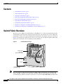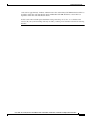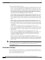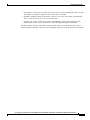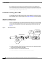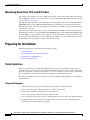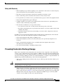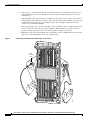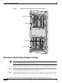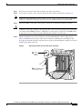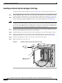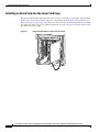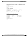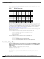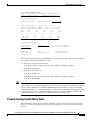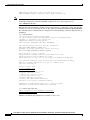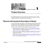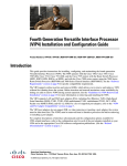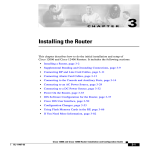
1
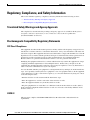
Cisco 12016, Cisco 12416, and Cisco 12816 Router
Clock and Scheduler, Switch Fabric, and Alarm
Card Replacement Instructions
Document Order Number: DOC-OL-13811-01, May 30, 2008
Product Numbers: 12016E-CSC=, 12016E-SFC=, 12416E-CSC=, 12416E-SFC=, 12816E-CSC, GSR16/80-CSC=,
GSR16/80-SFC=, GSR16/320-CSC=, GSR16/320-SFC=, 12816-CSC=, 12816-SFC=, GSR16-ALRM=
This publication contains removal and installation procedures for the clock and scheduler card (CSC),
the switch fabric card (SFC), and the alarm card used with Cisco 12016, Cisco 12416, and Cisco 12816
Routers. This publication also contains procedures for upgrading the switch fabric and instructions for
verifying the operation of the system after you replace a CSC, SFC, or alarm card. The CSC and SFC
are a card set referred to as the switch fabric. The alarm card is not a part of the switch fabric card set.
Americas Headquarters:
Cisco Systems, Inc., 170 West Tasman Drive, San Jose, CA 95134-1706 USA
Contents
Contents
•
Switch Fabric Overview, page 2
•
Alarm Card Overview, page 6
•
Preparing for Installation, page 8
•
Removing and Installing Switch Fabric Cards, page 11
•
Removing and Installing an Alarm Card, page 17
•
Upgrading the Switch Fabric, page 23
•
Troubleshooting the Switch Fabric, page 27
•
Regulatory, Compliance, and Safety Information, page 33
•
Obtaining Documentation and Submitting a Service Request, page 35
Switch Fabric Overview
The heart of Cisco 12016, Cisco 12416, and Cisco 12816 Routers is a crossbar switch fabric that provides
synchronized gigabit-speed interconnections between the line cards and the route processor (RP). The
switch fabric consists of two CSCs and three SFCs installed in the switch fabric card cage. As shown in
Figure 1, the air filter door swings down to allow access to the cage. One CSC and all three SFCs make
up the active switch fabric; the second CSC provides redundancy.
Figure 1
Switch Fabric Card Cage
RX
TX
IL
FA
D
LE
AB
EN
1
ROUTE PROCESSOR
P/H/F
FAST ETERNET
2
ALARM
C
SF
OC-12/STM-4 ATM
1
6DS3–SMB P/H/F
0
RX12DS3–SMB
C
CS
Q OC-3/STM-POS
OC-48/STM-16-SCPOS
11
0
Switch fabric
card cage
(behind filter door)
Air filter door
26195
Air filter
Captive screws
(2 on each side)
Note
The router supports online insertion and removal (OIR) of SFCs, meaning that you can remove and
replace and SFC, or upgrade your router with a new SFC, while the router remains powered up. The
recommended procedure for any fabric card removal is to perform a hw module shut command on the
Cisco 12016, Cisco 12416, and Cisco 12816 Router Clock and Scheduler, Switch Fabric, and Alarm Card Replacement Instructions
2
OL-13811-01
Switch Fabric Overview
card, wait for approximately 1 minute, and then remove the card. Primary CSC OIR results in traffic loss
regardless of the line cards installed in chassis. Redundant CSC OIR should not cause traffic loss
regardless of the line cards installed in chassis.
A CSC can be removed and replaced with the router powered up only if there is a redundant CSC
installed. If your system is running with only one CSC, you must power down the router before removing
the CSC.
Cisco 12016, Cisco 12416, and Cisco 12816 Router Clock and Scheduler, Switch Fabric, and Alarm Card Replacement Instructions
OL-13811-01
3
Switch Fabric Overview
There are currently six switch fabric options:
Note
•
Enhanced 2.5-Gbps switch fabric (80-Gbps switching system bandwidth) used in the Cisco 12016
Router—Consists of the 12016E-CSC and the 12016E-SFC fabric sets. Each SFC or CSC card
provides a 2.5-Gbps full-duplex connection to each line card in the system. Thus, for a Cisco 12016
Router with 16 line cards with 2 x 2.5 Gbps (full duplex), the system switching bandwidth is 16 x 5
Gbps = 80 Gbps. The enhanced fabric is required when enabling the Single-Router Automatic
Protection Switching (APS) or Building Integrated Timing Supply (BITS). It is also required when
configuring the chassis with 12000-SIP-401 2.5G SPA based line-card.
•
Enhanced 10-Gbps switch fabric (320-Gbps switching system bandwidth) used in the Cisco 12416
Router—Consists of the 12416E-CSC and the 12416E-SFC fabric sets. Each SFC or CSC card
provides a 10-Gbps full-duplex connection to each line card in the system. Thus, for a Cisco 12416
Router with 16 line cards with 2 x 10 Gbps (full duplex), the system switching bandwidth is 16 x 20
Gbps = 320 Gbps. The enhanced fabric is required when enabling the Single-Router APS or BITS
features.
•
Enhanced 40-Gbps switch fabric (1.2-Tbps switching system bandwidth) used in the Cisco 12816
Router—Consists of the 12816E-CSC and the 12816-SFC fabric sets. Each SFC or CSC card
provides a 40-Gbps full-duplex connection to each line card in the system. Thus, for a Cisco 12816
Internet Router with 16 line cards with 2 x 40 Gbps (full duplex), the system switching bandwidth
is 16 x 80 Gbps = 1.2 Tbps. The enhanced fabric is required when enabling the Single-Router APS
or BITS features.
•
2.5-Gbps switch fabric (80-Gbps switching system bandwidth) used in the Cisco 12016
Router—Consists of the GSR16/80-CSC and the GSR16/80-SFC fabric sets. Each SFC or CSC card
provides a 2.5-Gbps full-duplex connection to each line card in the system. Thus, for a Cisco 12016
Router with 16 line cards with 2 x 2.5 Gbps (full duplex), the system switching bandwidth is 16 x 5
Gbps = 80 Gbps.
•
10-Gbps switch fabric (320-Gbps switching system bandwidth) used in the Cisco 12416
Router—Consists of the GSR16/320-CSC and the GSR16/320-SFC fabric sets. Each SFC or CSC
card provides a 10-Gbps full-duplex connection to each line card in the system. Thus, for a
Cisco 12416 Router with 16 line cards with 2 x 10 Gbps (full duplex), the system switching
bandwidth is 16 x 20 Gbps = 320 Gbps.
•
40-Gbps switch fabric (1.2-Tbps switching system bandwidth) used in the Cisco 12816
Router—Consists of the 12816-CSC and the 12816-SFC fabric sets. Each SFC or CSC card provides
a 40-Gbps full-duplex connection to each line card in the system. Thus, for a Cisco 12816 Internet
Router with 16 line cards with 2 x 40 Gbps (full duplex), the system switching bandwidth is 16 x 80
Gbps = 1.2 Tbps.
Although they perform similar functions, you cannot intermix SFCs and CSCs. The switch fabric is a
card set. You must use either the 2.5-, 10-, or 40-Gbps switch fabric card set. Also, the 10-Gbps switch
fabric does not operate in one-quarter bandwidth mode as did some earlier models of the
Cisco 12000 Series routers.
Switch Fabric Card Types
The router ships from the factory with either one or two CSCs and three SFCs installed in the five slots
in the card cage. CSCs are installed in slot 0 or slot 1 (labeled CSC 0 or CSC 1); SFCs are installed in
slots 2, 3, and 4 (labeled SFC 0, SFC 1, or SFC 2).
The CSC provides the following functionality:
Cisco 12016, Cisco 12416, and Cisco 12816 Router Clock and Scheduler, Switch Fabric, and Alarm Card Replacement Instructions
4
OL-13811-01
Switch Fabric Overview
•
Switch fabric—Carries the user traffic between line cards or between the RP and a line card. The
switch fabric on the CSC is identical to the switch fabric on the SFC.
•
Scheduler—Handles requests from the line cards for access to the switch fabric and determines
when to allow the line cards access to the switch fabric.
•
System clock—Sent to all SFCs, line cards, and the RP. The system clock synchronizes data
transfers between line cards or between line cards and the RP through the switch fabric.
The SFC contains only the switch fabric circuitry, which carries user traffic between line cards or
between the RP and the line cards. It receives scheduling and system clock information from the CSC.
Cisco 12016, Cisco 12416, and Cisco 12816 Router Clock and Scheduler, Switch Fabric, and Alarm Card Replacement Instructions
OL-13811-01
5
Alarm Card Overview
The second CSC in the router provides data path, scheduler, and reference clock redundancy. The
interfaces between the line cards and the switch fabric are monitored constantly. If the system detects a
loss of synchronization (LOS), it automatically activates the data paths of the redundant CSC, and data
flows across the redundant path. The switch to the redundant CSC occurs within sub-seconds (the actual
switch time depends on your configuration and its scale).
Switch Fabric Card Cage Status LEDs
Status LEDs for all cards installed in the switch fabric card cage are located on the alarm card. There are
no status LEDs on the CSC or SFC. The alarm card has one pair of LEDs for each of the five card slots
in the switch fabric card cage. See the following section (Alarm Card Overview) for more information.
Alarm Card Overview
The router is equipped with two alarm cards. One card occupies the dedicated far left slot of the upper
card cage. A second alarm card occupies the dedicated far right slot of the lower card cage. In both card
cages, the alarm card slot differs from the rest of the card cage slots. It is labeled as an alarm card slot,
it comes with a pre-installed alarm card, and it has a different backplane connector than other cards
(Figure 2.)
Figure 2
Alarm Card (Front View)
C
C
CS
IL
FA
D
LE
FA
D
E
BL
AB
EN
Critical, major, and
minor alarm LEDs
L
R
R
CA AJO INO
M
M
0
2
1
Pin 1
C
CS
AL JOR OR
IC
IT MA MIN
CR
1
0
A
EN
T
O/L
AC
ALARM
Pin 25
Audio alarm
cutoff switch
IL
FA
D
LE
AB
N
E
IL
FA
D
LE
AB
N
E
0
1
26867
Handle
SF
IL
C
SF
0
1
2
ALARM
Clock and scheduler card
and switch fabric card LEDs
TI
I
CR
The router alarm card has three primary functions:
1.
Provides a visual display of three severity levels of alarms (critical, major, and minor) detected by
the system through the maintenance bus (MBus).
2.
Provides a connection to a site-wide external alarm system.
3.
Provides visual indicators of the status of the alarm card, CSCs, and SFCs.
Cisco 12016, Cisco 12416, and Cisco 12816 Router Clock and Scheduler, Switch Fabric, and Alarm Card Replacement Instructions
6
OL-13811-01
Alarm Card Overview
Monitoring Critical, Major, and Minor Alarm Status
The alarm card faceplate is equipped with three pairs of LEDs—labeled Critical, Major, and Minor—that
are used to identify system-level alarm conditions detected through the MBus.
Note
The LEDs are paired for redundancy to protect against a single failed LED. The critical and major alarm
LED pairs are red; the minor alarm LED pair is yellow.
Because the two alarm cards in the router are redundant, a system alarm condition detected through the
MBus causes the same LEDs to be illuminated on both alarm cards.
The alarms can warn of an overheating condition on a component in one of the card cages, a blower
failure in a blower module, an over-current condition in a power supply, or an out-of-tolerance voltage
on one of the cards in one of the card cages. The LEDs are driven by the MBus software, which sets the
threshold levels for triggering the different stages of alarms.
The RP continuously polls the system for temperature, voltage, current, and blower speed values. If an
over-threshold value is detected, the RP sets the appropriate alarm severity level on the alarm card, which
lights one of the LED pairs and energizes the appropriate alarm card relays, activating any external
audible or visual alarms wired to the alarm card. The RP also logs a message about the threshold
violation on the system console.
Alarm Relay Contact Connection
The alarm card faceplate is equipped with a 25-pin D-sub connector that is tied directly to the critical,
major, and minor alarm relay contacts (normally open, normally closed, and common).
Note
Only safety extra-low voltage (SELV) circuits can be connected to the connector labeled ALARM on the
alarm card faceplate. Maximum rating for the alarm circuit is 2A, 50 VA.
To comply with the intrabuilding lightning surge requirements of GR-1089-CORE, Issue II,
Revision 01, February 1999, you must use a shielded cable when connecting to the external alarm port
on the alarm card. The cable must consist of shielded cable terminated by shielded connectors on both
ends, with the cable shield material tied to both connectors.
The external alarm can be visual or audible. Audible external alarms can be silenced by pressing the
switch labeled ACO/LT (alarm cut-off/lamp test), on the alarm card faceplate. The ACO/LT switch does
not affect any visual (LED) alarms set on the alarm card. The audible alarm remains activated until the
alarm condition is cleared or this button is pressed. Visual alarms are reset by software.
Note
Because the two alarm cards in the router are redundant, you can silence an audible alarm by pressing
the audible alarm reset switch on either alarm card.
The ACO/LT switch also can be used to verify that the alarm card LEDs are capable of lighting. If no
audible alarm is active, pressing the ACO/LT switch temporarily illuminates the LEDs on the alarm card
faceplate as a visual check that no alarm card LEDs have failed.
Cisco 12016, Cisco 12416, and Cisco 12816 Router Clock and Scheduler, Switch Fabric, and Alarm Card Replacement Instructions
OL-13811-01
7
Preparing for Installation
Monitoring Alarm Card, CSC, and SFC Status
The alarm card faceplate has one pair of LEDs that provides a visual status of the alarm card, and five
pairs of LEDs that provide a visual status of the two CSCs and the three SFCs in the switch fabric card
cage (see Figure 2 on page 6).
The LED pair representing the alarm card itself is not labeled, and consists of one green LED labeled
ENABLED and one yellow LED labeled FAIL. When the green LED is on, this alarm card has been
detected by the router and is functioning properly. When the yellow LED is on, the router has detected
a fault in the alarm card.
Each card in the switch fabric card cage has a corresponding pair of LEDs on the alarm card faceplate.
Each LED pair consists of one green LED labeled ENABLED and one yellow LED labeled FAIL. When
the green LED is on, the card in the corresponding slot in the switch fabric card cage has been detected
by the system and is functioning correctly. When the yellow LED is on, the router has detected a fault
in the card in the corresponding slot in the switch fabric card cage.
Preparing for Installation
Installation preparation is presented in the following sections:
•
Safety Guidelines
•
Preventing Electrostatic Discharge Damage
•
Required Tools and Equipment
•
Related Documentation
Safety Guidelines
Before you perform any procedure in this publication, review the safety guidelines in this section to
avoid injuring yourself or damaging the equipment. In addition, review the safety warnings listed in the
Regulatory Compliance and Safety Information for the Cisco 12000 Series Internet Router publication
that accompanied your router before installing, configuring, or maintaining the router.
The following guidelines are for your safety and to protect equipment. The guidelines do not include all
hazards. Be alert.
Safety with Equipment
•
Always disconnect all power cords and interface cables before moving the system.
•
Never assume that power is disconnected from a circuit; always check.
•
Keep tools and assembly components away from walk areas.
•
Do not work alone if potentially hazardous conditions exist.
•
Do not perform any action that creates a potential hazard to people or makes the equipment unsafe.
•
Carefully examine your work area for possible hazards such as moist floors, ungrounded power
extension cables, and missing safety grounds.
Cisco 12016, Cisco 12416, and Cisco 12816 Router Clock and Scheduler, Switch Fabric, and Alarm Card Replacement Instructions
8
OL-13811-01
Preparing for Installation
Safety with Electricity
•
Before beginning any procedures requiring access to the interior of the router, locate the emergency
power-off switch for the room in which you are working.
•
Disconnect all power and external cables before installing or removing a router.
•
Never assume that power has been disconnected from a circuit; always check.
•
Do not perform any action that creates a potential hazard to people or makes the equipment unsafe.
•
Never install equipment that appears damaged.
•
Carefully examine your work area for possible hazards such as moist floors, ungrounded power
extension cables, and missing safety grounds.
•
If an electrical accident does occur, proceed as follows:
– Use caution; do not become a victim yourself. Disconnect power to the router.
– If possible, send another person to get medical aid; otherwise, assess the condition of the victim
and then call for help.
– Determine if the person needs rescue breathing or external cardiac compressions; then take
appropriate action.
In addition, observe the following guidelines when working with any equipment that is disconnected
from a power source but still connected to telephone or network wiring:
•
Never install telephone wiring during a lightning storm.
•
Never install telephone jacks in wet locations unless the jack is specifically designed for wet
locations.
•
Never touch uninsulated telephone wires or terminals unless the telephone line has been
disconnected at the network interface.
•
Use caution when installing or modifying telephone lines.
Preventing Electrostatic Discharge Damage
Many router components can be damaged by static electricity. Some components can be damaged by
voltages as low as 30V, while static voltages as high as 35,000V can be generated just by handling plastic
or foam packing material, or by sliding assemblies across plastic and carpets. Not exercising the proper
electrostatic discharge (ESD) precautions can result in intermittent or complete component failures. To
minimize the potential for ESD damage, observe the following guidelines:
•
Caution
Always use an ESD-preventive antistatic wrist strap or ankle strap and ensure that it makes good
skin contact.
You should periodically check the resistance value of the ESD-preventive strap. The measurement
should be between 1 and 10 megohms.
•
When removing or installing a component, make sure the equipment end of your antistatic strap
leash is connected to one of the ESD connection sockets on the front of the chassis or to a bare metal
surface on the chassis (see Figure 3). Avoid contact between the component and your clothing. The
ESD-preventive wrist strap only protects the component from ESD voltages on the body; ESD
voltages on your clothing can still cause component damage.
Cisco 12016, Cisco 12416, and Cisco 12816 Router Clock and Scheduler, Switch Fabric, and Alarm Card Replacement Instructions
OL-13811-01
9
Preparing for Installation
Figure 3
•
Always place a card component-side-up on an antistatic surface, in an antistatic card rack, or in a
static shielding bag. If you are returning the item to the factory, immediately place it in a static
shielding bag.
•
When installing a line card or route processor (RP), use the ejector levers to seat the card connectors
in the backplane, then tighten both captive screws on the faceplate of the card. These screws prevent
accidental removal, provide proper grounding for the router, and help to ensure that the card
connector is seated in the backplane.
•
When removing line cards, clock and scheduler cards, switch fabric cards, or an RP, use the ejector
levers to unseat the card connector from the backplane. Pull the metal card carrier out slowly,
placing one hand along the bottom of the carrier to guide it straight out of the slot.
•
Handle line cards, clock and scheduler cards, switch fabric cards, or an RP by the metal card carrier
edges only; avoid touching the board or any connector pins.
Connecting an ESD-Preventive Wrist Strap to the Chassis
DOWN
CDHNT
CDHNT
RA
RA
LOOP
LOOP
DOWN
CD
CD
LA
LA
TX
TX
0
0
RX
RX
TX
TX
0
1
1
RX
RX
TX
TX
2
2
R
VE IE T
TI RR PK
AC CA RX
T
EC
EJ
RX
RX
3
TX
TX
VE
TI RR
AC CA RX
4
4
R
IE LL
CE
RX
RX
R
VE IE T
TI RR PK
AC CA RX
X
AU
T
SE
RE
RX
RX
L
R
R
CA JO NO
ITI MA MI
CR
0
R
E IE T
TIV RR PK
AC CA RX
3
-1
OT
SL -0
OT
SL
TX
TX
1
TX
TX
5
2
5
RX
RX
LT
O/
AC
CO
NS
OL
E
TX
R
VE IE T
TI RR PK
AC CA RX
ESD
connection
socket
6
RX
TX
ALARM
7
3
RX
TX
8
R
VE IE T
TI RR PK
AC CA RX
K
LIN
RX
TX
LL
CO RX
TX
9
IL
FA
D
LE
AB
RX
EN
I
MI
TX
-45
RJ
10
RX
TX
IL
FA
D
LE
AB
EN
2
ALARM
C
SF
1
0
1
Q OC-3/STM-POS
RX
TX
IL
FA
D
LE
AB
EN
0
C
CS
P/H/F
11
RX12DS3–SMB
6DS3–SMB P/H/F
OC-12/STM-4 ATM
OC-48/STM-16-SCPOS
ROUTE PROCESSOR
10
-45
RJ
9
EN
RX
AB
LE
IL
FA
D
TX
I
MI
6
VE
TI RR
AC CA RX
R
IE T
PK
RX
TX
ALARM
7
3
RX
TX
8
RX
R
VE IE T
TI RR PK
AC CA RX
TX
TX
LL
CO RX
K
LIN
TX
E
OL
NS
LT
O/
AC
2
L
R
R
CA JO NO
ITI MA MI
CR
R
VE IE T
TI RR PK
AC CA RX
TX
TX
RX
RX
3
3
1
TX
TX
RX
R
VE IE T
TI RR PK
AC CA RX
0
TX
CD
LA
26208
CDHNT
RA
LOOP
LOOP
DOWN
CDHNT
RA
DOWN
LA
CD
TX
0
0
RX
RX
TX
TX
1
1
RX
RX
TX
TX
2
2
RX
0
T
EC
EJ
-1
OT
SL -0
OT
SL
R
E IE T
TIV RR PK
AC CA RX
X
AU
T
SE
RE
TX
4
4
RX
RX
R
VE IE LL
TI RR CE
AC CA RX
TX
5
5
RX
RX
CO
OOOOOOOOOOOOOOOOOOOOOOOOOOOOOOO
OOOOOOOOOO
OOOOOO
OOOOOOO
OOOOO
O
O
O
O
O
OOOOO
OO
OOOOO
OOOO
O
O
O
O
OOOO
OO
O
O
OOO
O
O
ROUTE PROCESSOR
FAST ETERNET
P/H/F
OC-12/STM-4 ATM
2
ALARM
C
SF
6DS3–SMB P/H/F
1
RX12DS3–SMB
0
FAST ETERNET
1
C
CS
Q OC-3/STM-POS
OC-48/STM-16-SCPOS
11
0
Cisco 12016, Cisco 12416, and Cisco 12816 Router Clock and Scheduler, Switch Fabric, and Alarm Card Replacement Instructions
10
OL-13811-01
Removing and Installing Switch Fabric Cards
Required Tools and Equipment
The following tools and equipment are required to remove and install a CSC, SFC, or alarm card:
•
ESD-preventive wrist strap
•
Flat-blade screwdriver
Related Documentation
The following publications contain additional information:
•
Cisco 12016, Cisco 12416, and Cisco 12816 Router Installation and Configuration Guide
•
Regulatory Compliance and Safety Information for the Cisco 12000 Series Internet Router
Removing and Installing Switch Fabric Cards
The switch fabric card cage is located below the upper card cage, behind the air filter door on the front
of the chassis (see Figure 1 on page 2.) The switch fabric card cage has five keyed, vertical card slots for
the CSCs and SFCs. CSCs are installed in the left two card slots (labeled CSC 0 and 1); SFCs are
installed in the right three slots (labeled SFC 0, 1, and 2).
Note
The router supports online insertion and removal (OIR) of SFCs, meaning that you can remove and
replace and SFC, or upgrade your router with a new SFC, while the router remains powered up. The
recommended procedure for any fabric card removal is to perform a hw module shut command on the
card, wait for approximately 1 minute, and then remove the card. Primary CSC OIR results in traffic loss
regardless of the line cards installed in chassis. Redundant CSC OIR should not cause traffic loss
regardless of the line cards installed in chassis.
A CSC can be removed and replaced with the router powered up only if there is a redundant CSC
installed. If your system is running with only one CSC, you must power down the router before removing
the CSC.
Cisco 12016, Cisco 12416, and Cisco 12816 Router Clock and Scheduler, Switch Fabric, and Alarm Card Replacement Instructions
OL-13811-01
11
Removing and Installing Switch Fabric Cards
Procedures for removing and installing a CSC and SFC are described in the following sections:
•
Removing a Card from the Switch Fabric Card Cage, page 12
•
Installing a Card into the Switch Fabric Card Cage, page 13
•
Verifying the Installation, page 16
These procedures apply to all available switch fabric card sets (2.5-, 10-, and 40-Gbps). When removing
and replacing cards, pay close attention to the ejector levers on the cards. Newer cards only pivot 70
degrees away from the card, while the ejector levers on some older cards pivot 90 degrees away from the
card.
Removing a Card from the Switch Fabric Card Cage
To remove a card from the switch fabric card cage, follow these steps:
Step 1
Attach an ESD-preventive wrist strap to your wrist and connect the leash to one of the ESD connection
sockets on the front of the chassis or to a bare metal surface on the chassis (see Figure 3 on page 10).
Step 2
Open the air filter door on the front of the chassis, which shows the air filter door swung open (Figure 4).
Figure 4
Opening the Air Filter Door
RX
TX
IL
FA
D
LE
AB
EN
1
ROUTE PROCESSOR
P/H/F
FAST ETERNET
2
ALARM
C
SF
OC-12/STM-4 ATM
1
6DS3–SMB P/H/F
0
RX12DS3–SMB
C
CS
Q OC-3/STM-POS
OC-48/STM-16-SCPOS
11
0
Switch fabric
card cage
(behind filter door)
Air filter door
26195
Air filter
Captive screws
(2 on each side)
a.
Loosen the two captive screws on each side of the air filter door.
b.
Grasp the sides of the air filter door front cover and carefully swing the door out and down, away
from the switch fabric card cage.
The air filter door is attached to the chassis by a pair of spring-loaded arms on either side of the door.
When the door is fully extended away from the fabric card cage, it hangs down in front of the lower
card cage.
Cisco 12016, Cisco 12416, and Cisco 12816 Router Clock and Scheduler, Switch Fabric, and Alarm Card Replacement Instructions
12
OL-13811-01
Removing and Installing Switch Fabric Cards
Caution
On routers with the bezel extender kit installed on the line card and RP card cage front covers, you must
remove the extended front cover from the lower line card and RP card cage before attempting to open
the air filter door. When the extended front cover is mounted on the chassis, the air filter door does not
have adequate free space to open completely.
Caution
Be especially careful not to damage the honeycomb screen on the back of the air filter door and on the
inside of the switch fabric card cage. Damaging the honeycomb screen can restrict the air flow and cause
overheating in the router. It can also diminish EMI protection.
Step 3
Identify the card to be replaced in the switch fabric card cage. Grasp the two card ejector levers and
simultaneously pivot both ejector levers 90 degrees (70 degrees for newer switch fabric cards) away from
the front edge of the card carrier to unseat the card from the backplane connector (Figure 5).
Step 4
Touching only the metal card carrier, slide the card out of the slot and place it directly into an antistatic
sack or other ESD-preventive container.
If you plan to return the defective card to the factory, repackage it in the shipping container you received
with the replacement card.
Figure 5
Removing a Card from the Switch Fabric Card Cage
Switch fabric card
26862
Air filter door
Installing a Card into the Switch Fabric Card Cage
Install the CSCs into the two far left slots of the switch fabric card cage. Install the SFCs into the three
far right slots.
To install a card into the switch fabric card cage, use Figure 6 as a reference and follow these steps:
Cisco 12016, Cisco 12416, and Cisco 12816 Router Clock and Scheduler, Switch Fabric, and Alarm Card Replacement Instructions
OL-13811-01
13
Removing and Installing Switch Fabric Cards
Step 1
Attach an ESD-preventive wrist strap to your wrist and connect the leash to one of the ESD connection
sockets on the front of the chassis or to a bare metal surface on the chassis (see Figure 3 on page 10).
Step 2
Grasp the card carrier handle with one hand and place your other hand under the carrier to support and
guide it into the correct slot. Slide the card halfway into the slot. Avoid touching the card circuitry or
any connectors.
Note
There are alignment grooves on each slot in the fabric card cage. When you reinstall a card in
the fabric card cage, make sure that you align both edges of the card carrier in the slot grooves.
Step 3
Pivot both card ejector levers so the openings on the card ejector cams at the top and bottom of the card
pass over the tabs on each side of the card cage slot.
Caution
Verify that the openings on the card ejector cams pass over the tabs; otherwise, one or both ejector levers
might bind when you attempt to close the ejector levers, thereby damaging or breaking one or both
ejector levers.
Step 4
Continue sliding the card into the card cage slot until the openings on the card ejector cams engage the
tabs on each side of the card cage slot.
Note
Step 5
CSCs and SFCs have guide pins that make initial contact with the backplane connector as you
slide a card into its slot. After the guide pins make contact, continue pushing on the card carrier
until the card ejector levers begin pivoting forward, toward the handle in the card carrier.
To seat the card in the backplane connector, grasp both card ejector levers and pivot them inward toward
the handle in the card carrier until they are flush against the front edge of the card carrier.
Figure 6
Installing a Card in the Switch Fabric Card Cage
Switch fabric card
26862
Air filter door
Cisco 12016, Cisco 12416, and Cisco 12816 Router Clock and Scheduler, Switch Fabric, and Alarm Card Replacement Instructions
14
OL-13811-01
Removing and Installing Switch Fabric Cards
Step 6
Close and fasten the air filter door as follows:
a.
Caution
All four sides of the air filter door are lined with EMI-preventive gaskets consisting of many raised,
conductive contacts. Align and seat the door carefully to avoid damaging the EMI-preventive gasket
contacts. A damaged gasket can result in reduced EMI performance.
b.
Caution
Pivot the air filter door up so that it is aligned with the opening of the switch fabric card cage and
the four guide pins are inserted in the corresponding holes on each side of the switch fabric card
cage (Figure 7).
Push firmly on the air filter door until it is seated in the opening of the switch fabric card cage, then
tighten the four captive screws.
The air filter door must be closed and secured at all times to maintain correct EMI performance.
Figure 7
Closing the Chassis Air Filter Door
RX
TX
IL
FA
D
LE
AB
EN
1
ROUTE PROCESSOR
P/H/F
FAST ETERNET
2
ALARM
C
SF
OC-12/STM-4 ATM
1
6DS3–SMB P/H/F
0
RX12DS3–SMB
C
CS
Q OC-3/STM-POS
OC-48/STM-16-SCPOS
11
0
Switch fabric
card cage
(behind filter door)
Guide pin
Captive screw
Air filter
Captive screws
(2 on each side
27962
Air filter
door
Cisco 12016, Cisco 12416, and Cisco 12816 Router Clock and Scheduler, Switch Fabric, and Alarm Card Replacement Instructions
OL-13811-01
15
Removing and Installing Switch Fabric Cards
Verifying the Installation
To verify that the new CSC or SFC is working properly, follow these steps:
Step 1
Step 2
Check the following components to make sure they are secure:
•
The cards in the switch fabric card cage are fully seated in their slots, and the card ejector levers are
flush with the front edge of the card carriers.
•
The air filter door is up and seated in the switch fabric card cage opening, and the four captive screws
are tightened.
Observe the five pairs of switch fabric status LEDs on the alarm cards (leftmost slot in the upper card
cage; rightmost slot in the lower card cage). Both alarm cards should display the same LED status:
•
The green LED labeled ENABLED for each installed CSC and SFC should be on.
If one of the green LEDs is off, either the corresponding slot in the switch fabric card cage is empty,
or the card in that slot has not been installed correctly. Try reseating the card in the backplane
connector.
•
The yellow LED labeled FAIL for each installed CSC and SFC should be off.
If one of the yellow LEDs is on, the system has detected a fault in the card installed in the
corresponding slot. The card might not be installed completely or could have an internal fault. Try
reseating the card in its slot. If that does not resolve the problem, contact your Cisco service
representative for assistance.
Cisco 12016, Cisco 12416, and Cisco 12816 Router Clock and Scheduler, Switch Fabric, and Alarm Card Replacement Instructions
16
OL-13811-01
Removing and Installing an Alarm Card
Removing and Installing an Alarm Card
The router is equipped with two alarm cards. One card occupies the dedicated far left slot of the upper
card cage; the second occupies the dedicated far right slot of the lower card cage (see Figure 8). In both
card cages, the alarm card slot differs from the rest of the card cage slots in that it is labeled as an alarm
card slot, is physically narrower, and has a different backplane connector.
Procedures for removing and installing an alarm card are described in the following sections:
Caution
•
Removing an Alarm Card from the Upper Card Cage, page 18
•
Installing an Alarm Card into the Upper Card Cage, page 20
•
Removing an Alarm Card from the Lower Card Cage, page 21
•
Installing an Alarm Card into the Lower Card Cage, page 22
•
Checking the Replacement Alarm Card, page 23
There is a caution label on the panel beside both alarms cards. For the upper cage alarm card, the label
reads: For screw alignment, ensure that slot 0 is populated when inserting or removing alarm card. For
the lower cage alarm card, the label reads: For screw alignment, ensure that slot 15 is populated when
inserting or removing alarm card. Line card slots adjacent to the alarm cards must always be populated.
Cisco 12016, Cisco 12416, and Cisco 12816 Router Clock and Scheduler, Switch Fabric, and Alarm Card Replacement Instructions
OL-13811-01
17
Removing and Installing an Alarm Card
Figure 8
Alarm Card Locations in the Upper and Lower Card Cages
DOWN
CDHNT
CDHNT
RA
RA
LOOP
LOOP
DOWN
CD
CD
LA
LA
Upper card cage
TX
TX
0
0
RX
RX
TX
TX
0
1
1
RX
RX
TX
TX
2
2
R
VE IE T
TI RR PK
AC CA RX
T
EC
EJ
RX
RX
3
TX
TX
R
VE IE LL
TI RR CE
AC CA RX
4
4
RX
RX
R
VE IE T
TI RR PK
AC CA RX
X
AU
T
SE
RE
RX
RX
L
R
R
CA JO NO
ITI MA MI
CR
0
R
E IE T
TIV RR PK
AC CA RX
3
-1
OT
SL -0
OT
SL
TX
TX
1
TX
TX
5
2
5
RX
RX
LT
O/
AC
CO
NS
OL
E
TX
R
VE IE T
TI RR PK
AC CA RX
6
RX
TX
ALARM
7
3
RX
TX
8
R
VE IE T
TI RR PK
AC CA RX
K
LIN
RX
TX
TX
LL
CO RX
Alarm card
9
RX
AB
EN
IL
FA
D
LE
I
MI
TX
-45
RJ
10
RX
TX
IL
FA
D
LE
AB
EN
2
ALARM
C
SF
1
0
1
Q OC-3/STM-POS
R
IE T
PK
LT
O/
AC
2
L
R
R
CA JO NO
ITI MA MI
CR
R
VE IE T
TI RR PK
AC CA RX
TX
TX
R
IE T
PK
VE
TI RR
AC CA RX
0
TX
CD
LA
27965
CDHNT
RA
LOOP
LOOP
DOWN
CDHNT
RA
DOWN
LA
CD
TX
0
0
RX
RX
TX
TX
1
1
Lower card cage
RX
RX
TX
TX
2
2
RX
RX
TX
1
TX
3
3
RX
RX
R
E IE T
TIV RR PK
AC CA RX
T
EC
EJ
-1
OT
SL -0
OT
SL
0
X
AU
T
SE
RE
TX
4
4
RX
RX
R
VE IE LL
TI RR CE
AC CA RX
TX
5
5
RX
RX
CO
NS
OL
TX
E
6
R
VE IE T
TI RR PK
AC CA RX
RX
TX
ALARM
7
3
RX
TX
8
VE
TI RR
AC CA RX
RX
K
LIN
TX
TX
LL
CO RX
9
EN
RX
AB
LE
IL
FA
D
TX
I
MI
10
-45
RJ
RX
TX
IL
FA
D
LE
AB
EN
0
C
CS
P/H/F
11
RX12DS3–SMB
6DS3–SMB P/H/F
OC-12/STM-4 ATM
OC-48/STM-16-SCPOS
ROUTE PROCESSOR
ROUTE PROCESSOR
FAST ETERNET
P/H/F
OC-12/STM-4 ATM
2
ALARM
C
SF
6DS3–SMB P/H/F
1
RX12DS3–SMB
0
FAST ETERNET
1
C
CS
Q OC-3/STM-POS
OC-48/STM-16-SCPOS
11
0
Alarm card
Removing an Alarm Card from the Upper Card Cage
Note
The router alarm card supports online insertion and removal (OIR). This allows you to remove and install
an alarm card while the router remains powered up.
To remove the alarm card from the upper card cage, use Figure 9 as a reference and follow these steps:
Step 1
Grasp the outside edges of the upper card cage front cover and pull it straight out to detach the front
cover from the ball stud sockets on the front of the card cage.
Step 2
Attach an ESD-preventive wrist strap to your wrist and connect the leash to one of the ESD connection
sockets on the front of the chassis or to a bare metal surface on the chassis (see Figure 3 on page 10).
Cisco 12016, Cisco 12416, and Cisco 12816 Router Clock and Scheduler, Switch Fabric, and Alarm Card Replacement Instructions
18
OL-13811-01
Removing and Installing an Alarm Card
Step 3
Disconnect any external alarm cable attached to the alarm card connector.
Step 4
Loosen the two captive screws at the top and bottom of the alarm card faceplate (see Figure 9a).
Note
Step 5
Caution
Step 6
Unlike line cards and the RP, the alarm card does not have card ejector levers. The alarm card backplane
connector is smaller, has fewer pins, and is easier to seat and unseat than line cards and the RP.
Pull on the handle on the alarm card faceplate to unseat the card from the backplane connector.
One edge of the card carrier faceplate is lined with an EMI-preventive gasket consisting of many raised,
conductive contacts. Be careful not to damage the gasket contacts, because a damaged card carrier gasket
can result in reduced EMI performance. Additionally, to ensure proper compression of the EMI gaskets,
be sure slot 0 or slot 15 are always populated during replacement of an alarm card.
Pull the card halfway out of its slot and place your other hand under the carrier to support it (see
Figure 9b). Slide the alarm card out of the card slot and place it immediately on the antistatic mat.
If you plan to return the old alarm card to the factory, repackage it in the shipping container you received
with the replacement alarm card.
Figure 9
Removing an Alarm Card from the Upper Card Cage
DOWN
CDHNT
CDHNT
RA
RA
LOOP
LOOP
DOWN
a Loosen
captive
screws
CD
CD
LA
LA
TX
TX
0
0
RX
RX
TX
TX
0
1
1
RX
RX
TX
TX
2
2
R
VE IE T
TI RR PK
AC CA RX
T
EC
EJ
RX
RX
3
0
TX
TX
R
VE IE LL
TI RR CE
AC CA RX
4
4
RX
RX
R
VE IE T
TI RR PK
AC CA RX
X
AU
RX
RX
T
SE
RE
R
E IE T
TIV RR PK
AC CA RX
3
-1
OT
SL -0
OT
SL
TX
TX
1
TX
TX
5
2
5
RX
RX
CO
NS
OL
E
TX
R
VE IE T
TI RR PK
AC CA RX
6
RX
TX
L
R
R
CA JO NO
ITI MA MI
CR
7
3
RX
TX
8
R
VE IE T
TI RR PK
AC CA RX
K
LIN
RX
TX
TX
LL
CO RX
LT
O/
AC
9
RX
I
MI
TX
-45
RJ
10
ALARM
RX
TX
ROUTE PROCESSOR
FAST ETERNET
OC-12/STM-4 ATM
P/H/F
IL
FA
D
LE
6DS3–SMB P/H/F
RX12DS3–SMB
AB
OC-48/STM-16-SCPOS
11
Q OC-3/STM-POS
EN
b Use handle to pull
card out of slot
IL
FA
D
LE
AB
EN
0
1
C
CS
0
1
28347
2
ALARM
C
SF
Cisco 12016, Cisco 12416, and Cisco 12816 Router Clock and Scheduler, Switch Fabric, and Alarm Card Replacement Instructions
OL-13811-01
19
Removing and Installing an Alarm Card
Installing an Alarm Card into the Upper Card Cage
To install an alarm card into the upper card cage, use Figure 10 as a reference and follow these steps:
Step 1
Attach an ESD-preventive wrist strap to your wrist and connect the leash to one of the ESD connection
sockets on the front of the chassis or to a bare metal surface on the chassis (see Figure 3 on page 10).
Step 2
Grasp the handle on the alarm card faceplate with one hand and place your other hand under the card
carrier to support the card while guiding it into the card cage slot labeled Alarm 0 (see Figure 10a.)
Caution
One edge of the card carrier faceplate is lined with an EMI-preventive gasket consisting of many raised,
conductive contacts. Be careful not to damage the gasket contacts, because a damaged card carrier gasket
can result in reduced EMI performance. Additionally, to ensure proper compression of the EMI gaskets,
be sure slot 0 or slot 15 is always populated during replacement of an alarm card.
Step 3
Carefully slide the alarm card carrier into the slot until it makes contact with the backplane connector,
then stop. Avoid touching the card circuitry or any connectors.
Step 4
Carefully push on the top and bottom of the alarm card faceplate to seat it in the backplane connector.
Step 5
Check to be sure that all slots are filled, especially slot 0 beside the alarm card. After all slots are
populated, tighten the two captive screws to secure the alarm card in the card slot (see Figure 10b).
Step 6
Connect any external device cable to the connector on the alarm card faceplate.
Step 7
Replace the upper card cage front cover.
Figure 10
Installing an Alarm Card into the Upper Card Cage
RA
CDHNT
CDHNT
LOOP
DOWN
RA
DOWN
LOOP
b Tighten
captive
screws
CD
CD
LA
LA
TX
TX
0
0
RX
RX
TX
TX
0
1
1
RX
RX
TX
TX
2
2
R
VE IE T
TI RR PK
AC CA RX
T
EC
EJ
RX
RX
3
0
TX
TX
R
VE IE LL
TI RR CE
AC CA RX
4
4
RX
RX
R
VE IE T
TI RR PK
AC CA RX
X
AU
RX
RX
T
SE
RE
R
E IE T
TIV RR PK
AC CA RX
3
-1
OT
SL -0
OT
SL
1
TX
TX
TX
TX
5
2
5
RX
RX
CO
NS
OL
E
TX
R
VE IE T
TI RR PK
AC CA RX
6
RX
TX
L
R
R
CA JO NO
ITI MA MI
CR
7
3
RX
TX
8
R
VE IE T
TI RR PK
AC CA RX
K
LIN
RX
TX
TX
LL
CO RX
LT
O/
AC
9
RX
I
MI
TX
-45
RJ
10
ALARM
RX
TX
ROUTE PROCESSOR
FAST ETERNET
P/H/F
OC-12/STM-4 ATM
RX12DS3–SMB
IL
FA
D
LE
OC-48/STM-16-SCPOS
11
AB
6DS3–SMB P/H/F
Q OC-3/STM-POS
EN
a Align and insert
alarm card
IL
FA
D
LE
AB
EN
0
1
C
CS
0
1
28348
2
ALARM
C
SF
Cisco 12016, Cisco 12416, and Cisco 12816 Router Clock and Scheduler, Switch Fabric, and Alarm Card Replacement Instructions
20
OL-13811-01
Removing and Installing an Alarm Card
Removing an Alarm Card from the Lower Card Cage
The alarm card in the lower card cage occupies the dedicated far right slot labeled Alarm 1. Except for
the head-down orientation in the lower card cage (see Figure 11), the alarm card in the lower card cage
is removed in exactly the same way as described in the “Removing an Alarm Card from the Upper Card
Cage” section on page 18.
Cisco 12016, Cisco 12416, and Cisco 12816 Router Clock and Scheduler, Switch Fabric, and Alarm Card Replacement Instructions
OL-13811-01
21
Removing and Installing an Alarm Card
Installing an Alarm Card into the Lower Card Cage
Except for the head-down orientation in the lower card cage (see Figure 11), the alarm card is installed
in the lower card cage in exactly the same way as described in the “Installing an Alarm Card into the
Upper Card Cage” section on page 20. Check to be sure that all slots are filled, especially slot 15 beside
the alarm card. After all slots are populated, tighten the two captive screws to secure the alarm card in
the card slot (see Figure 10b).
P/H/F
Q OC-3/STM-POS
R
VE IE T
TI RR PK
AC CA RX
TX
RX
8
TX
2
R
VE IE T
TI RR PK
AC CA RX
TX
TX
R
VE IE T
TI RR PK
AC CA RX
0
RX
TX
CD
LA
28349
CDHNT
RA
LOOP
LOOP
DOWN
CDHNT
RA
DOWN
LA
CD
TX
0
0
L
R
R
CA JO NO
ITI MA MI
CR
RX
TX
TX
1
1
0
RX
RX
LT
O/
AC
TX
TX
2
2
RX
RX
TX
1
TX
3
3
RX
RX
R
E IE T
TIV RR PK
AC CA RX
R
VE IE T
TI RR PK
AC CA RX
T
EC
EJ
-1
OT
SL -0
OT
SL
ALARM
0
1
X
AU
T
SE
RE
TX
4
4
RX
RX
R
VE IE LL
TI RR CE
AC CA RX
R
VE IE T
TI RR PK
AC CA RX
TX
5
5
RX
RX
2
EN
CO
AB
NS
LE
OL
IL
FA
D
E
6
R
VE IE T
TI RR PK
AC CA RX
RX
TX
7
3
RX
1
C
CS
R
VE IE T
TI RR PK
AC CA RX
IL
FA
D
LE
AB
EN
0
3
0
TX
1
C
SF
2
ALARM
R
VE IE T
TI RR PK
AC CA RX
K
LIN
TX
LL
CO RX
9
RX
TX
I
MI
10
-45
RJ
RX
TX
11
RX12DS3–SMB
6DS3–SMB P/H/F
OC-12/STM-4 ATM
OC-48/STM-16-SCPOS
Q OC-3/STM-POS
FAST ETERNET
Alarm Card Orientation in the Lower Card Cage
ROUTE PROCESSOR
Figure 11
Cisco 12016, Cisco 12416, and Cisco 12816 Router Clock and Scheduler, Switch Fabric, and Alarm Card Replacement Instructions
22
OL-13811-01
Upgrading the Switch Fabric
Checking the Replacement Alarm Card
To check the replacement alarm card installation, follow these steps:
Step 1
Step 2
Verify that each of the following conditions is true:
•
The replacement alarm card is fully seated in its slot and both captive screws are tightened.
•
If an external alarm cable is connected to the alarm card, the connector is completely seated and
held in place by the hold-down hardware.
Visually check the LEDs on the two alarm cards. When the system is operating correctly, the following
LED conditions should be true:
•
All three system alarm LEDs should be off.
•
The alarm card status LED labeled ENABLED should be on; the LED labeled FAIL should be
off.
•
The LED labeled ENABLED for each CSC and SFC in the switch fabric card cage should be
on; the LED labeled FAIL should be off.
If the alarm card does not initialize properly, refer to the Cisco 12016, Cisco 12416, and Cisco 12816
Router Installation and Configuration Guide for additional information and installation troubleshooting
procedures. If you are still unable to resolve the problem, contact your Cisco service representative for
assistance.
Upgrading the Switch Fabric
The switch fabric on the Cisco 12016 and the Cisco 12416 Routers can be upgraded in the field. This
allows you to upgrade a 2.5- or 10-Gbps switch fabric to a higher performance switch fabric.
Cisco 12016 Routers can be upgraded from a 2.5-Gbps switch fabric to a 10- or 40-Gbps switch fabric.
Cisco 12416 Routers can be upgraded from a 10-Gbps switch fabric to a 40-Gbps switch fabric. Table 1
lists the Cisco router model numbers, their corresponding switch fabric speed, and the available upgrade
path for each router model.
Table 1
Switch Fabric Upgrade Paths
Router Model
Switch Fabric
Speed
Cisco 12016 Router
2.5 Gbps
Upgrade Path
•
Cisco 12416 Router
or
•
Cisco 12816 Router
Cisco 12416 Router
10 Gbps
Cisco 12816 Router
Cisco 12816 Router
40 Gbps
NA
Cisco 12016, Cisco 12416, and Cisco 12816 Router Clock and Scheduler, Switch Fabric, and Alarm Card Replacement Instructions
OL-13811-01
23
Upgrading the Switch Fabric
Upgrade Requirements
Before proceeding, review the following upgrade requirements:
1.
You must have a complete switch fabric card set. You cannot intermix 2.5-, 10-, and 40-Gbps CSCs
and SFCs.
2.
When upgrading to a 10-Gbps switch fabric with a GRP installed, the Flash memory card must be
loaded with Cisco IOS Release 12.0(16)S or later.
3.
When upgrading to a 10-Gbps switch fabric with a PRP installed, the Flash memory card must be
loaded with Cisco IOS Release 12.0(22)S or later.
4.
When upgrading to a 40-Gbps switch fabric, the Performance Route Processor (PRP) must be
installed, and the flash memory card must be loaded with Cisco IOS Release 12.0(31)S or later.
5.
When upgrading to an enhanced 10-Gbps switch fabric, the Performance Route Processor (PRP)
must be installed, and the flash memory card must be loaded with Cisco IOS 12.0(32)SY2 or later.
6.
When upgrading to an enhanced 40-Gbps switch fabric, the Performance Route Processor (PRP)
must be installed, and the flash memory card must be loaded with Cisco IOS 12.0(31)S or later.
Cisco 12016, Cisco 12416, and Cisco 12816 Router Clock and Scheduler, Switch Fabric, and Alarm Card Replacement Instructions
24
OL-13811-01
Upgrading the Switch Fabric
Upgrade Procedures
To upgrade the switch fabric, follow these steps:
Step 1
Turn off power to the router.
Step 2
Remove all CSCs and SFCs. See the “Removing a Card from the Switch Fabric Card Cage” section on
page 12.
Step 3
Install the new CSCs and SFCs. See the “Installing a Card into the Switch Fabric Card Cage” section on
page 13.
Note
Although they perform similar functions, you cannot intermix SFCs and CSCs. The switch fabric
is a card set. You must use either the 10- or 40-Gbps switch fabric card set.
Step 4
Insert a Flash memory card into the GRP or PRP, making sure that it is loaded with the appropriate Cisco
IOS Release, noted in the “Upgrade Requirements” section on page 24.
Step 5
Turn on power to the router and wait for all installed line cards to fully boot before proceeding to the
next step.
Note
Let the router return to full operation before proceeding to the next step. This may take a
considerable amount of time depending upon the configuration of the router.
Step 6
At the privileged EXEC prompt, enter the configure terminal command to enter global configuration
mode.
Step 7
If you are using a Cisco IOS Release prior to 12.0(27)S, enter the service upgrade all command. If not,
skip to the next step.
Step 8
If you are using Cisco IOS Release 12.0(27)S or later, enter the service upgrade mbus-agent-rom
command.
Step 9
Cisco 12.0(27)S or later users also need to enter the service upgrade fabric-downloader command.
Step 10
After the commands have finished running, press Ctrl-z to exit configuration mode.
Step 11
See the next section, Verifying the Upgrade.
Note
Additional information is available on the Cisco TAC website. Refer to the Cisco 12000 Series Internet
Router Upgrade Procedure document.
Verifying the Upgrade
To verify that the upgraded switch fabric is operating properly, follow these steps:
Step 1
Perform all the steps listed in the “Upgrading the Switch Fabric” section on page 23.
Step 2
Run the show gsr command to see if the new switch fabric cards are detected by the system.
Cisco 12016, Cisco 12416, and Cisco 12816 Router Clock and Scheduler, Switch Fabric, and Alarm Card Replacement Instructions
OL-13811-01
25
Upgrading the Switch Fabric
Note
Step 3
The show gsr command output varies slightly between each switch fabric card set.
See the “Troubleshooting the Switch Fabric” section on page 27 if you encounter problems. Also review
the next section, Post-Upgrade Considerations.
Cisco 12016, Cisco 12416, and Cisco 12816 Router Clock and Scheduler, Switch Fabric, and Alarm Card Replacement Instructions
26
OL-13811-01
Troubleshooting the Switch Fabric
Post-Upgrade Considerations
After performing an upgrade and verifying its installation, there are some post-upgrade considerations.
•
Cisco 12000 Series routers include a label on the side of the chassis that indicates the model of the
router. The switch fabric upgrade kit does not include a new label to identify the upgraded router
model. For example, if you upgrade a Cisco 12416 Router to a Cisco 12816 Router, the label on the
side of the chassis still identifies the chassis as a Cisco 12416 Router. Cisco recommends that you
take the necessary administrative steps to properly identify an upgraded router.
•
The alternative methods for identifying an upgraded router are through the label on the switch fabric
cards or through Cisco IOS software, using the show gsr command. Table 2 lists the router model
and the number on the corresponding switch fabric card identification labels.
Table 2
Identifying Switch Fabric Cards
Router Model
Switch Fabric Card Identification Label
Cisco 12016 Router
SFC-80 and CSC-80
Cisco 12416 Router
SFC-320 and CSC-320
Cisco 12816 Router
SFC-1280 and CSC-1280
Troubleshooting the Switch Fabric
This section describes the procedures needed to troubleshoot problems with the switch fabric. The RP
and the line cards connect through the crossbar switch fabric, which provides a high-speed physical path
for most inter-card communication. Among the messages passed between the RP and the line cards over
the switch fabric are, actual packets being routed and received, forwarding information, traffic statistics,
and most management and control information. This information is useful in diagnosing
hardware-related failures.
Note
This section is recommended only for advanced Cisco IOS software operators and system administration
personnel. Refer to the appropriate Cisco IOS software publications for detailed Cisco IOS information.
To troubleshoot the switch fabric, follow these steps:
Step 1
Collect the needed data from the RPs and line cards.
Note
When you connect to the line card, use the attach command. The execute-on command is
dependent upon the inter-process communication (IPC) which operates over the switch fabric.
If you are having problems with IPC, the commands that run remotely through the switch fabric
can time out. The attach <slot #> command travels over the MBus and not the IPC.
Step 2
Use the show controllers fia command on the primary and secondary RPs and save the output.
Step 3
Use the attach <slot #> command to access a line card.
Step 4
Use the show controllers fia command on all installed line cards and save the output from each.
Cisco 12016, Cisco 12416, and Cisco 12816 Router Clock and Scheduler, Switch Fabric, and Alarm Card Replacement Instructions
OL-13811-01
27
Troubleshooting the Switch Fabric
Step 5
Gather the output and proceed to the Analyzing the Data section.
Analyzing the Data
Switch fabric problems can occur due to failures in any of the following components:
•
RP
•
Line card hardware
•
Backplane
•
CSCs/SFCs
When troubleshooting switch fabric errors, you need to look for patterns with regard to which
components are reporting errors. For example, if you combine the show controllers fia output from all
the RPs and line cards, you can determine if there is an error pattern. The following subsections discuss
the values within the output that can help you determine any error patterns.
crc16 Output
The crc16 data line from the show controllers fia command is an important indicator of hardware
problems. If one line card or one CSC/SFC has been on line inserted and removed, you can expect to see
some crc16 error data. However, this number should not continue to increase. If the number is increasing,
you may need to replace some faulty hardware. It is very important to correlate the data from both the
primary RP and the secondary RP and all installed line cards. The example output below shows the status
of the primary RP. The crc16 data line is underlined and is showing errors from sfc1.
Router#show controllers fia
Fabric configuration: Full bandwidth, redundant fabric
Master Scheduler: Slot 17 Backup Scheduler: Slot 16
From Fabric FIA Errors
----------------------redund fifo parity 0
redund overflow 0
cell drops 0
crc32 lkup parity 0
cell parity
0
crc32
0
Switch cards present
0x001F
Slots 16 17 18 19 20
Switch cards monitored 0x001F
Slots 16 17 18 19 20
Slot:
16
17
18
19
20
Name:
csc0
csc1
sfc0
sfc1
sfc2
-----------------------------------los
0
0
0
0
0
state Off
Off
Off
Off
Off
crc16 0
0
0
1345
0
To Fabric FIA Errors
----------------------sca not pres 0
req error
0
uni FIFO overflow
grant parity 0
multi req
0
uni FIFO undrflow
cntrl parity 0
uni req
0
crc32 lkup parity
multi FIFO
0
empty dst req 0
handshake error
cell parity 0
0
0
0
0
Cisco 12016, Cisco 12416, and Cisco 12816 Router Clock and Scheduler, Switch Fabric, and Alarm Card Replacement Instructions
28
OL-13811-01
Troubleshooting the Switch Fabric
In the example output below, you can see the status of the line card in slot 2. The crc16 data line is
underlined and is showing errors from sfc1. Remember to use the attach command and not the
execute-on command to access the line cards.
Router#attach 2
Entering Console for 4 port ATM Over SONET OC-3c/STM-1 in Slot: 2
Type "exit" to end this session
Press RETURN to get started!
LC-Slot2>
LC-Slot2>enable
LC-Slot2#show controllers fia
From Fabric FIA Errors
----------------------redund FIFO parity 0
redund overflow 0
cell drops 0
crc32 lkup parity 0
cell parity
0
crc32
0
Switch cards present
0x001F
Slots 16 17 18 19 20
Switch cards monitored 0x001F
Slots 16 17 18 19 20
Slot:
16
17
18
19
20
Name:
csc0
csc1
sfc0
sfc1
sfc2
-----------------------------------Los
0
0
0
0
0
state Off
Off
Off
Off
Off
crc16 0
0
0
1345
0
To Fabric FIA Errors
----------------------sca not pres 0
req error
0
uni fifo overflow 0
grant parity 0
multi req
0
uni fifo undrflow 0
cntrl parity 0
uni req
0
crc32 lkup parity 0
multi fifo
0
empty DST req 0
handshake error
0
cell parity 0
LC-Slot2#exit
Disconnecting from slot 2.
Connection Duration: 00:00:21
Router#
Cisco 12016, Cisco 12416, and Cisco 12816 Router Clock and Scheduler, Switch Fabric, and Alarm Card Replacement Instructions
OL-13811-01
29
Troubleshooting the Switch Fabric
Once you have gathered the show controllers fia command data from the RPs and line cards, you can
create a table similar to Table 3.
Table 3
Card Slot
Error Data Collection Table
CSC 0
CSC 1
SFC 0
0
SFC 1
SFC 2
SFC 3
SFC 4
ERROR
1
2
ERROR
3
ERROR
4
5
ERROR
6
7
ERROR
8
This table indicates that more than one line card is reporting errors coming from SFC 1. Therefore, the
first step is to change this SFC. Whenever a replacement is recommended, first verify that the card is
correctly seated. You should ALWAYS reseat the corresponding card to be sure it is correctly seated. If,
after reseating the card, the CRCs are still increasing, then go ahead and replace the part. See the
“Properly Seating Switch Fabric Cards” section on page 31.
The common failure patterns and recommended actions for crc16 errors are as follows (one step at a time
until the problem goes away):
1.
Errors indicated on more than one line card from the same switch fabric card:
a. Replace the switch fabric card in the slot corresponding to the errors
b. Replace all switch fabric cards
c. Replace the backplane
2.
Errors indicated on one line card from more than one switch fabric card:
a. Replace the line card
b. If errors are incrementing, replace the current master CSC
c. If errors are not incrementing and the current master is CSC0, replace CSC1
Grant Parity and Request Errors
Another troubleshooting indicator comes from the console logs or the output of the show log command,
in the form of grant parity and request errors. Look for the following type of message that indicates a
grant parity error:
%FABRIC-3-PARITYERR: To Fabric parity error was detected.
Grant parity error Data = 0x2.
SLOT 1:%FABRIC-3-PARITYERR: To Fabric parity error was detected.
Grant parity error Data = 0x1
You can also use the output from the show controllers fia command. Important information is
underlined:
Cisco 12016, Cisco 12416, and Cisco 12816 Router Clock and Scheduler, Switch Fabric, and Alarm Card Replacement Instructions
30
OL-13811-01
Troubleshooting the Switch Fabric
Router#show controllers fia
Fabric configuration: Full bandwidth, redundant fabric
Master Scheduler: Slot 17
Backup Scheduler: Slot 16
From Fabric FIA Errors
----------------------redund FIFO parity 0
redund overflow 0
crc32 lkup parity 0
cell parity 0
Switch cards present
0x001F
Slots
Switch cards monitored 0x001F
Slots
Slot:
16
17
18
Name:
csc0
csc1
sfc0
---------------------Los
0
0
0
state Off
Off
Off
crc16 876
257
876
To Fabric FIA Errors
----------------------sca not pres 0
req error
grant parity 1
multi req
cntrl parity 0
multi fifo
0
cell parity 0
cell drops 76
crc32 0
16 17 18 19 20
16 17 18 19 20
19
20
sfc1
sfc2
--------------0
0
Off
Off
876
876
1
0
uni fifo overflow 0
uni fifo undrflow 0
uni req
0
empty DST req 0
crc32 lkup parity 0
handshake error
0
The common failure patterns and recommended actions for grant parity and request errors are as follows
(one step at a time until the problem goes away):
1.
Grant errors on more than one line card:
a. Replace the CSC (see the note below to know which one should be swapped)
b. Replace the backplane
2.
Grant errors on one line card:
a. Replace the line card
a. Replace the CSC (see the note below to know which one should be swapped)
b. Replace the backplane
Note
If multiple line cards are reporting grant parity or request errors and the router is still functioning, then
a CSC switchover has occurred. The failed CSC is the one that is currently the backup CSC (not the one
listed as “Master Scheduler” in the show controllers fia output). If “Halted” is next to the heading
“From Fabric FIA Errors” or “To Fabric FIA Errors”, or if the router is no longer forwarding traffic, then
a CSC switchover has not occurred and the failing CSC is the one listed as “Master Scheduler.” By
default, the CSC in slot 17 is the primary and the CSC in slot 16 is the backup.
Properly Seating Switch Fabric Cards
The switch fabric cards in the router can be challenging to insert, and may require a small amount of
force to seat correctly. If either of the CSCs are not seated properly, you may see the following error
message:
Cisco 12016, Cisco 12416, and Cisco 12816 Router Clock and Scheduler, Switch Fabric, and Alarm Card Replacement Instructions
OL-13811-01
31
Troubleshooting the Switch Fabric
%MBUS-0-NOCSC: Must have at least 1 CSC card in slot 16 or 17
%MBUS-0-FABINIT: Failed to initialize switch fabric infrastructure
Note
You may also get this error message if there are only enough CSCs and SFCs seated for quarter
bandwidth configurations. Quarter bandwidth configurations are no longer supported on
Cisco 12000 Series Routers.
When dealing with switch fabric and line card booting problems, it is important to verify that all CSCs
and SFCs are correctly seated and powered on. The output from the show version and show controllers
fia commands tells you which hardware configuration is currently running on the box. Important data is
underlined.
Router#show version
Cisco Internetwork Operating System Software
IOS (tm) GS Software (GSR-P-M), Experimental Version 12.0(20010505:112551)
Copyright (c) 1986-2001 by cisco Systems, Inc.
Compiled Mon 14-May-01 19:25 by tmcclure
Image text-base: 0x60010950, data-base: 0x61BE6000
ROM: System Bootstrap, Version 11.2(17)GS2, [htseng 180]
EARLY DEPLOYMENT RELEASE SOFTWARE (fc1)
BOOTFLASH: GS Software (GSR-BOOT-M), Version 12.0(15.6)S,
EARLY DEPLOYMENT MAINTENANCE INTERIM SOFTWARE
Router
System
System
System
uptime is 17 hours, 53 minutes
returned to ROM by reload at 23:59:40 MET Mon Jul 2 2001
restarted at 00:01:30 MET Tue Jul 3 2001
image file is "tftp://172.17.247.195/gsr-p-mz.15S2plus-FT-14-May-2001"
cisco 12016/GRP (R5000) processor (revision 0x01) with 262144K bytes of memory.
R5000 CPU at 200Mhz, Implementation 35, Rev 2.1, 512KB L2 Cache
Last reset from power-on
2 Route Processor Cards
1 Clock Scheduler Card
3 Switch Fabric Cards
1 8-port OC3 POS controller (8 POs).
1 OC12 POS controller (1 POs).
1 OC48 POS E.D. controller (1 POs).
7 OC48 POS controllers (7 POs).
1 Ethernet/IEEE 802.3 interface(s)
17 Packet over SONET network interface(s)
507K bytes of non-volatile configuration memory.
20480K bytes of Flash PCMCIA card at slot 0 (Sector size 128K).
8192K bytes of Flash internal SIMM (Sector size 256K).
Router#show controller fia
Fabric configuration: Full bandwidth nonredundant
Master Scheduler: Slot 17
Additional troubleshooting information is available on Cisco.com.
Cisco 12016, Cisco 12416, and Cisco 12816 Router Clock and Scheduler, Switch Fabric, and Alarm Card Replacement Instructions
32
OL-13811-01
Regulatory, Compliance, and Safety Information
Regulatory, Compliance, and Safety Information
This section includes regulatory, compliance, and safety information in the following sections:
•
Translated Safety Warnings and Agency Approvals
•
Electromagnetic Compatibility Regulatory Statements
Translated Safety Warnings and Agency Approvals
The complete list of translated safety warnings and agency approvals is available in the Regulatory
Compliance and Safety Information for Cisco 12000 Series Internet Routers publication.
(Document Number 78-4347-xx.)
Electromagnetic Compatibility Regulatory Statements
FCC Class B Compliance
The equipment described in this manual generates and may radiate radio-frequency energy. If it is not
installed in accordance with Cisco’s installation instructions, it may cause interference with radio and
television reception. This equipment has been tested and found to comply with the limits for a Class B
digital device in accordance with the specifications in part 15 of the FCC rules. These specifications are
designed to provide reasonable protection against such interference in a residential installation.
However, there is no guarantee that interference will not occur in a particular installation.
Modifying the equipment without Cisco’s written authorization may result in the equipment no longer
complying with FCC requirements for Class B digital devices. In that event, your right to use the
equipment may be limited by FCC regulations, and you may be required to correct any interference to
radio or television communications at your own expense.
You can determine whether your equipment is causing interference by turning it off. If the interference
stops, it was probably caused by the Cisco equipment or one of its peripheral devices. If the equipment
causes interference to radio or television reception, try to correct the interference by using one or more
of the following measures:
• Turn the television or radio antenna until the interference stops.
• Move the equipment to one side or the other of the television or radio.
• Move the equipment farther away from the television or radio.
• Plug the equipment into an outlet that is on a different circuit from the television or radio. (That is,
make certain the equipment and the television or radio are on circuits controlled by different circuit
breakers or fuses.)
CISPR 22
This apparatus complies with CISPR 22/EN55022 Class B radiated and conducted emissions
requirements.
Cisco 12016, Cisco 12416, and Cisco 12816 Router Clock and Scheduler, Switch Fabric, and Alarm Card Replacement Instructions
OL-13811-01
33
Regulatory, Compliance, and Safety Information
Canada
English Statement of Compliance
This class A digital apparatus complies with Canadian ICES-003.
French Statement of Compliance
Cet appareil numérique de la classe A est conforme à la norme NMB-003 du Canada.
Europe (EU)
This apparatus complies with EN55022 Class B and EN55024 standards when used as ITE/TTE
equipment, and EN300386 for Telecommunications Network Equipment (TNE) in both installation
environments, telecommunication centers and other indoor locations.
VCCI Class A Notice for Japan
Warning
This is a Class A product based on the standard of the Voluntary Control Council
for Interference by Information Technology Equipment (VCCI). If this equipment
is used in a domestic environment, radio disturbance may arise. When such
trouble occurs, the user may be required to take corrective actions.
Statement 191
Class A Notice for Hungary
Warning
This equipment is a class A product and should be used and installed properly
according to the Hungarian EMC Class A requirements (MSZEN55022). Class A
equipment is designed for typical commercial establishments for which special
conditions of installation and protection distance are used. Statement 256
Cisco 12016, Cisco 12416, and Cisco 12816 Router Clock and Scheduler, Switch Fabric, and Alarm Card Replacement Instructions
34
OL-13811-01
Regulatory, Compliance, and Safety Information
Class A Notice for Taiwan and Other Traditional Chinese Markets
Warning
This is a Class A Information Product, when used in residential environment, it
may cause radio frequency interference, under such circumstances, the user
may be requested to take appropriate countermeasures. Statement 257
Class A Notice for Korea
Warning
This is a Class A Device and is registered for EMC requirements for industrial
use. The seller or buyer should be aware of this. If this type was sold or
purchased by mistake, it should be replaced with a residential-use type.
Statement 294
Obtaining Documentation and Submitting a Service Request
For information on obtaining documentation, submitting a service request, and gathering additional
information, see the monthly What’s New in Cisco Product Documentation, which also lists all new and
revised Cisco technical documentation, at:
http://www.cisco.com/en/US/docs/general/whatsnew/whatsnew.html
Subscribe to the What’s New in Cisco Product Documentation as a Really Simple Syndication (RSS) feed
and set content to be delivered directly to your desktop using a reader application. The RSS feeds are a free
service and Cisco currently supports RSS version 2.0.
CCDE, CCENT, Cisco Eos, Cisco Lumin, Cisco Nexus, Cisco StadiumVision, the Cisco logo, DCE, and Welcome to the Human Network are
trademarks; Changing the Way We Work, Live, Play, and Learn is a service mark; and Access Registrar, Aironet, AsyncOS, Bringing the Meeting To
You, Catalyst, CCDA, CCDP, CCIE, CCIP, CCNA, CCNP, CCSP, CCVP, Cisco, the Cisco Certified Internetwork Expert logo, Cisco IOS,
Cisco Press, Cisco Systems, Cisco Systems Capital, the Cisco Systems logo, Cisco Unity, Collaboration Without Limitation, EtherFast, EtherSwitch,
Event Center, Fast Step, Follow Me Browsing, FormShare, GigaDrive, HomeLink, Internet Quotient, IOS, iPhone, iQ Expertise, the iQ logo,
iQ Net Readiness Scorecard, iQuick Study, IronPort, the IronPort logo, LightStream, Linksys, MediaTone, MeetingPlace, MGX, Networkers,
Networking Academy, Network Registrar, PCNow, PIX, PowerPanels, ProConnect, ScriptShare, SenderBase, SMARTnet, Spectrum Expert,
StackWise, The Fastest Way to Increase Your Internet Quotient, TransPath, WebEx, and the WebEx logo are registered trademarks of
Cisco Systems, Inc. and/or its affiliates in the United States and certain other countries.
All other trademarks mentioned in this document or Website are the property of their respective owners. The use of the word partner does not imply
a partnership relationship between Cisco and any other company. (0805R)
© 2008 Cisco Systems, Inc. All rights reserved.
Cisco 12016, Cisco 12416, and Cisco 12816 Router Clock and Scheduler, Switch Fabric, and Alarm Card Replacement Instructions
OL-13811-01
35
Regulatory, Compliance, and Safety Information
Cisco 12016, Cisco 12416, and Cisco 12816 Router Clock and Scheduler, Switch Fabric, and Alarm Card Replacement Instructions
36
OL-13811-01