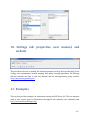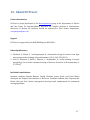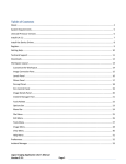
1
2014 Neural Circuit Tracer Software for automated tracing of neurites from light microscopy stacks User Guide of images Version 4.0 Contents 1. Introduction .................................................................................................................................................. ‐ 2 ‐ 2. System requirements and installation .............................................................................................. ‐ 2 ‐ 3. File tab: loading, opening, and saving libraries ............................................................................. ‐ 2 ‐ 4. Image Processing tab: MatLab and ImageJ plugins ..................................................................... ‐ 4 ‐ 5. Automated Tracing tab: initial trace, automated branch merger, and online training ‐ 5 ‐ 6. Trace Editing & Analysis tab: trace editing, optimization, and finding loops .................. ‐ 8 ‐ 7. Manage Plugins tab: adding and removing MatLab and ImageJ plugins ......................... ‐ 11 ‐ 8. View tab: image stack, z‐projection, 3D view, and console ................................................... ‐ 12 ‐ 9. Macros tab: creating and running macros .................................................................................... ‐ 14 ‐ 10. Settings tab: properties, user manual, and website ............................................................. ‐ 15 ‐ 11. Examples ................................................................................................................................................. ‐ 15 ‐ 12. About NCTracer ................................................................................................................................... ‐ 17 ‐ ‐ 1 ‐ 1. Introduction Neural Circuit Tracer (NCTracer) is open source software built using Java and MatLab. The software is based on the core of ImageJ (http://rsbweb.nih.gov/ij) and the graphic user interface was developed in Java Swings. NCTracer combines a number of ImageJ functions with several newly developed algorithms for automated and manual tracing of neurites. The software is designed in a way that allows the user to add Java and MatLab based plugins, build and run macros. These and other functionalities of NCTracer are described in detail below. 2. System requirements and installation NCTracer 4.0 is developed for the Windows 7 and 8, 64‐bit operating systems and requires a minimum of 4 GB of RAM. This version of the software does not run on Mac or Linux OS. To install NCTracer 4.0 download NCTracer_4_0.zip file located at http://www.neurogeometry.net/resources/tools and extract its components. Right‐click on Setup.exe file and run it as Administrator. This will install four components: Java (jre‐7‐ windows‐x64), Java3D (java3d‐1_5_2‐windows‐amd64), MatLab Runtime Compiler (MCR_R2013a_win64), and NCTracer (NCT_4_0). It is recommended that you install all four components even if some versions of these components are already present on your computer. To run NCTracer double‐click on the NCTracer icon, , created on your desktop. 3. File tab: loading, opening, and saving libraries ‐ 2 ‐ The current version of NCTracer supports image stacks saved in several standard image file formats, as well as the MatLab data file format (.mat). Traces must be saved in the .mat or the SWC formats of neuron morphology. To load a new image stack click on the Load Library button located in the File tab of the main NCTracer window. After selecting an image from the stack of images a new Load Library dialog box (right) will appear. The user may select the images to be loaded by providing a starting image number, an increment, and a characteristic string contained in the file names. Image stack can be reduced in the x, y, and z dimensions during loading. The user must specify the reduction factors (positive doubles) and chose one of five reduction methods: Min, Max, Mean, Median, and SD. The loaded stack of images will be displayed in the Image Stack window (below). This window allows the user to scroll through the individual image planes within the stack. Multiple image stacks can be loaded sequentially. The dropdown list of open image stacks is located at the bottom of the main NCTracer window. This list can be used to change the currently selected stack of images. All operations performed in the NCTracer will be applied to the currently selected stack only. The original image stack, the pre‐ processed image stack, and the trace are collectively referred to as the Library. The Save Library button located in the File tab or icon located in the main NCTracer window saves these components in the MatLab (.mat) data file format. ‐ 3 ‐ To open a library click on the Open Library button located in the File tab of the main NCTracer window. The user can import / export the trace of neurites by clicking on the Import SWC / Export to SWC buttons. The entire trace, as well as individual trees contained in the trace can be exported. In the latter case follow the instructions given in the Trace Editing & Analysis tab section. Import / export features only support the SWC format of neuron morphology. 4. Image Processing tab: MatLab and ImageJ plugins The Image Processing tab contains a number of custom filters written in MatLab and plugins adapted from ImageJ. These functions can be used to enhance the intensity of neurites and reduce image background prior to performing automated tracing. The current version of NCTracer includes the following image processing plugins: MatLab plugins ImageJ plugins Eliminate Small Regions Accurate Gaussian Blur Multi‐Scale Gaussian Auto Gamma Multi‐Scale LoG CLAHE Simple Filters Contrast & Brightness Adjuster Image Stabilizer Threshold Adjuster Subtract Background Convolver Mean Shift Variance Filter Threshold Background FFT Bandpass Filter RATS Unsharp Mask FeatureJ Filters Rank Filters Hessian CP Measures Hybrid 3D Median Filter Rolling Ball Background Sigma Filter Plus ‐ 4 ‐ New plugins can be created and the existing plugins can be removed in the Manage Plugins tab. All image processing operations can be undone / redone by pressing Ctrl+Z / Ctrl+Y or by clicking on the / icons located at the bottom of the main NCTracer window. 5. Automated Tracing tab: initial trace, automated branch merger, and online training The main steps of the automated tracing algorithm are described in detail in [1, 2]. Briefly, they include the following components: Preprocessing: Image stack may be filtered to smooth the intensity along the neurites and sharpen the transition between the neurites and the background. Initial trace: The centerline of all neurites contained in the image is detected with the Fast Marching [2] or Voxel‐Coding [1] algorithms. In the latter case it is necessary to eliminate image background by setting a threshold; the algorithm will be slow if the number of voxels remaining in the foreground is much higher than 105. Erroneous short terminal branches and small loop clusters are eliminated by the tracing algorithms. The resulting trace is optimized as described in [2] and is referred to as the initial trace (right). Fixing topological errors: Initial traces of complex arbors or arbors of multiple neurons may contain topological errors. The number of ‐ 5 ‐ such errors can be reduced by using the geometrical and topological features of different branch merging scenarios (see [2] for details). All branch merging scenarios are considered by the algorithm, and the weighted features of each scenario are combined into a fitness function. The weights are determined during online training, and branch merging scenarios with the highest overall fitness are implemented by the algorithm. Complex mergers, involving more than 12 branch endpoints, are not carried out in this version of the software. To perform automated tracing, the user must click on the Get Initial Trace button located in the Automated Tracing tab of the main NCTracer window and select the Fast Marching or the Voxel‐Coding algorithm (right). If Fast Marching is selected, the user will need to generate the seed points prior to executing the algorithm. The seed points can be generated automatically by using the Fast Marching dialog box (left) or manually by right‐clicking over the Image Stack window and using the seed point selection menu (right). The initial trace will be generated and displayed in the Image Stack window. If necessary, the user may edit the initial trace by switching to the Trace Editing & Analysis tab. If the initial trace contains multiple topological errors, such errors can be automatically corrected by using the online training module of NCTracer. To reduce the number of topological errors, click on the Calculate Costs button to generate cost components for the branch merging scenarios. Load the Training History (see below), and click on the Automated Merger button. The initial trace will be broken down to the level of disconnected branches, reassembled into tree structures based on the prior training history, and redisplayed. ‐ 6 ‐ The above steps can be combined into a macro and run sequentially, with no user involvement (see the Macros tab section). The user may adjust the parameters of the automated tracing algorithms by clicking on the Properties button located in the Settings tab. Progression of the automated tracing algorithm can be monitored in the Console window. Automated tracing time depends on the image size and the complexity of neurites. Training history files can be created in the online training module of the software. These files can be generalized on image stacks obtained under similar experimental conditions (same class of neurites, labeling / imaging technique). To create a training history file load the image stack, obtain its initial trace, and calculate the cost components (as described above). Clicking on the Online Training button will open the Online Training table. The Online Training table shows branch merging scenarios for different clusters of branch points (rows of the table). One such cluster is shown in the image on the next page. Clicking on different rows of the table or right‐clicking on different parts of the initial trace in the Image Stack window will move the focus (squares) from one cluster to another. To view different branch merging scenarios within the selected cluster click on + (next scenario) or – (previous scenario) signs, or select a scenario number from the dropdown window in the table. ‐ 7 ‐ Once the correct scenario is selected, the user must assign to it a positive weight (typically 1). Weighted scenarios will be highlighted in yellow (see the table above). After such training on several clusters of branch points select WPerceptron or WSVM classifier and click on the Apply button to generate the Training History. Correctly classified branch mergers will be highlighted with green in the table, while erroneous mergers will be highlighted in red. Erroneous mergers need to be corrected or their weights must be reduced to zero to ensure that the classifiers are not trained on errors. The user may continue training or save training history and move to another training stack. New training examples will be appended to the old training history as long as the latter is loaded (check the loaded Training History path in the Automated Tracing tab). Training on about 100 clusters of branch point is typically sufficient to achieve error rates of less than 5%. Ambiguous branch merging examples should not be used for training. 6. Trace Editing & Analysis tab: trace editing, optimization, and finding loops The Trace Editing & Analysis tab makes it possible to trace neurites manually and/or edit automated traces. Right‐click over the Image Stack window to open the manual tracing menu (image on the next page) and enable the following functionalities: ‐ 8 ‐ Select Start and click at a desired location in the Image Stack window to initiate tracing of a new tree structure. Continue clicking within the Image Stack window to add vertices. Each new vertex will be connected to the previous vertex with a straight‐line segment. Tracing can be continued from any vertex of the tree. Select Continue, place the cursor in the vicinity of the vertex, and click on the vertex to activate it. Connect Vertices makes it possible to connect any two vertices of the trace with a segment. The user will be prompted if this operation results in the formation of a loop. Individual segments of the trace can be eliminated by selecting the Delete Segment function, and moving the cursor to the vicinity of the segment’s vertices. Clicking on one of these vertices will activate its neighbors. A subsequent click on one of these neighboring vertices will eliminate the connecting segment. Delete Tree, followed by mouse over the tree vertices will highlight the entire tree. A subsequent click on one of the vertices will result in the deletion of the tree. Individual vertices of the trace can be moved in x, y, and z directions. Select Move Vertices function and click and drag the vertex in the selected plane. To move the vertex to a different plane, scroll through the stack to the desired z‐location and click on the vertex. Individual trees can be moved in x, y, and z directions. Select Move Tree function, click and drag a vertex of a selected tree to move the tree in the current plane. To move the tree to a different plane, click‐hold on a vertex of the tree and scroll through the stack to the desired z‐location. To export a single tree in the SWC format the user may select Export Tree to SWC and move the mouse over the tree of interest to highlight it. A subsequent click on any of the vertices of the tree will initiate the export process. To export the entire trace the user must click on the Export to SWC button located in the File tab of the main NCTracer window. End terminates the previously selected action and disables active vertices. During manual tracing, the user can scroll through the image planes of the stack (by using the slide bar at the bottom of the Image Stack window or the mouse wheel), zoom‐in, zoom‐out (with Page Up / Down), and pan in the plane of the stack (arrow keys). Manual tracing operations can be undone / redone by pressing Ctrl+Z / Ctrl+Y or by clicking on the / icons located at the bottom of the main NCTracer window. The user must be in the Trace Editing & Analysis tab to perform undo / redo operations on the trace. ‐ 9 ‐ The intensity and the xyz coordinates of an image voxel at the position of the cursor, as well as the caliber (radius) and the xyz coordinates of a trace vertex closest to that location are displayed in the main NCTracer window. Trace segments whose vertices are located in the current plane of view are drawn with slightly thicker lines. Trace can be switched on and off, viewed on a z‐projection and in 3D (see the View tab section). These views can be refreshed by clicking on the icon. The trace can be optimized with two optimization functions located in the Trace Editing & Analysis tab of the main NCTracer window (details of these optimization procedures are described in [2]). The Optimize Trace function (right) optimizes both the positions and calibers of vertices in the trace. Branch and terminal points can be kept fixed during the optimization. Default values of optimization parameters are displayed in the Optimize Trace dialog box. The Optimize Radius function (below) calculates the optimal calibers of trace vertices, while the vertex positions remain unchanged. The average density of trace vertices (number / length) can be adjusted with the Adjust Point Density function located in the Trace Editing & Analysis tab of the main NCTracer window. The Eliminate Small Trees button allows the user to automatically delete trees, the total length of which is less than a user defined length threshold. Loops in the trace (if present) can be displayed by pressing the Show / Hide Loops button. ‐ 10 ‐ 7. Manage Plugins tab: adding and removing MatLab and ImageJ plugins NCTracer allows the user to import plugins designed for ImageJ. To import an ImageJ plugin check the ImageJ Plugins radio button and click on Add Plugins. The user will need to find and open the main file (.jar, .java, or .class) associated with the plugin. The plugin will be copied into the \My Documents\NCTracer\plugins folder, and will automatically appear in the list of plugins in the Image Processing tab. Functions written in MatLab can also be converted into NCTracer plugins. In this case the user must first deploy MatLab Builder JA (http://www.mathworks.com/products/javabuilder/) to create a .jar file associated with the MatLab function. The version of MatLab Builder JA must match the version of the MatLab Runtime Compiler used to run NCTracer. Once the .jar file is created it can be imported into NCTracer by checking the MatLab Plugins radio button and clicking on Add Plugins. This will open the MatLab Plugin Type selection window (right). NCTracer 4.0 supports three types of plugins: plugins which modify the image stack (e.g. an image processing plugin), plugins which generate or modify the trace (e.g. a plugin that finds and eliminates short terminal branches), or none of the above (e.g. a plugin which calculates lengths of all trees contained in the trace). Clicking OK will open the Input / Output Selection window (below), in which the user must specify the name, type, order, and default value of every input and output variable of the MatLab function. There are four variables which must be formatted in a specific way to ‐ 11 ‐ work with NCTracer. These variables include: Image Stack (3D MatLab array), Adjacency Matrix (N×N array of doubles), Position Vector (N×3 array of doubles), and Branch Caliber (N×1 array of doubles). N here denotes the number of vertices in the trace. Variables that are not in use must be removed from the Input / Output Selection window by un‐ checking the corresponding check‐boxes. Additional input / output parameters may be included by specifying the number and the order of these parameters in the Input / Output Selection window. Newly added plugins, which modify the image stack or the trace, will appear in the list of MatLab Filters and Plugins located in the Image Processing tab. Trace analysis plugins will appear in the list of Custom MatLab Plugins in the Trace Editing & Analysis Tab. ImageJ and MatLab plugins can be removed from NCTracer by selecting the plugin type and clicking on the Remove Plugins button. 8. View tab: image stack, zprojection, 3D view, and console ‐ 12 ‐ The View tab of the main NCTracer window allows the user to display the stack on a z‐projection and in 3D. The user can switch between the Original and Preprocessed image stacks (radio buttons), as well as display / hide the trace (Trace check box). The user can scroll through the individual image planes with the slide bar located at the bottom of the Image Stack window or by using the mouse wheel. All views can be refreshed by clicking on the icon in the main NCTracer window. All three views are equipped with zoomin, zoomout, and pan features. In the Image Stack and Z‐Projection windows these features can be accessed by clicking on the , , or icons at the bottom of the main NCTracer window and then clicking on the image or dragging the image with the mouse. Alternatively, these functions can be controlled with Page Up / Down and the arrow keys. The user can determine the xyz coordinates and the intensity of any voxel in the Image Stack window or any pixel in the Z‐Projection window by pointing the cursor at that location. The information will be displayed in the main NCTracer window. Positions and calibers of the trace vertices can be displayed in a similar manner. In the 3D View window (http://rsb.info.nih.gov/ij/plugins/3d‐ viewer/) zoom‐in and zoom‐out features are controlled with Page Up, Page Down, or the mouse wheel. ‐ 13 ‐ Panning can be done by pressing the arrow keys while holding down Shift. The image stack can be rotated in 3D by using the mouse or the arrow keys. The View tab also displays the Console window (right) which records all operations performed by the user and the software. Saving this log will create a text file in the \My Documents\NCTracer\logs folder. 9. Macros tab: creating and running macros The user can create, save, and run sequences of operations (macros) to be performed on image stacks. To create a macro, click on the Macros tab in the main NCTracer window and assemble the desired macro components in the Macro Selection panel (image on the next page). You will be prompted to provide parameter values for every function included in the macro. Click on Save to create a text file containing the macro sequence. The file will be saved in the \My Documents\NCTracer\macros folder. To run the macro click on the Run Macro button and select the macro file. ImageJ plugins cannot be included in a macro in this version of the software. ‐ 14 ‐ 10. Settings tab: properties, user manual, and website This tab allows the user to modify the default parameters used by the Fast Marching, Voxel Coding, trace optimization, branch merging, and online learning algorithms. The Settings tab also contains the links to this User Manual and the Neurogeometry group website, http://www.neurogeometry.net. 11. Examples This section provides examples of automated tracing with NCTracer 4.0. The two datasets used in this section (and in illustrations throughout this manual) were obtained from http://www.diademchallenge.org/. ‐ 15 ‐ Tracing a single arbor File tab Load an image stack (e.g. any of the Olfactory Projection axons). No reduction is necessary. Automated Tracing tab Click on Get Initial Trace and select the Fast Marching method. Generate the seed points automatically, or right‐click over the Image Stack window to open the seed point menu and place the seed points manually. Start Fast Marching and let it run until one of the stopping conditions is encountered. You may pause and continue Fast Marching at any time during this process. Click on Complete to generate the initial trace Tracing multiple arbors File tab Load an image stack (e.g. axons of layer 6 neurons). No reduction is necessary. Image Processing tab Apply Multi‐scale LoG plugin: Minimum Radius = 2, Step Size = 1, Maximum Radius = 2. Use Threshold Background plugin: Threshold = 10 to 25 Use Eliminate Small Regions plugin: Minimum Region Size = 100. Automated Tracing tab Click on Get Initial Trace and select the Voxel Coding method. Click Ok and let the algorithm generate the initial trace. Load Training History: Documents\NCTracer\training‐history\TrainingHistory_L6.mat Click on Calculate Costs. Click on Automated Merger. The above tracing sequences may be written into macros (see the Macros tab section) and run without any input from the user. Automated tracing of individual stacks from the above two datasets may take several minutes. The results can be edited in the Trace Editing & Analysis tab, saved in the .mat format, and exported as .swc files. ‐ 16 ‐ 12. About NCTracer Contact information NCTracer is being developed by the Neurogeometry group at the Department of Physics and the Center for Interdisciplinary Research on Complex Systems at Northeastern University in Boston. All inquiries should be addressed to Prof. Armen Stepanyants, [email protected]. Support NCTracer is supported by the NIH/NINDS grant NS063494. Related publications 1. Chothani, P., Mehta, V., and Stepanyants A., Automated tracing of neurites from light microscopy stacks of images, Neuroinformatics, 9(2‐3): 263–278 (2011) 2. Gala, R., Chapeton, J., Jitesh, J., Bhavsar, C., Stepanyants, A., Active learning of neuron morphology for accurate automated tracing of neurites, Frontiers in Neuroanatomy, 8: 37 (2014) Individual contributions Graduate students Chintan Bhavsar, Paarth Chothani, Jayant Jitesh, and Vivek Mehta developed the Graphic User Interface of NCTracer. Graduate students Julio Chapeton and Rohan Gala and Prof. Armen Stepanyants developed and implemented the automated tracing algorithms. ‐ 17 ‐