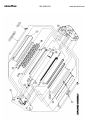
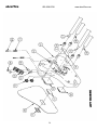
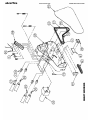
1
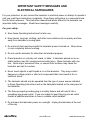
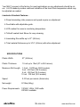
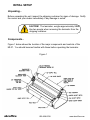
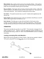
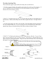
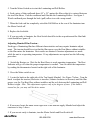
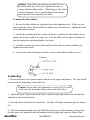
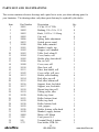
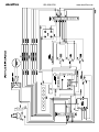
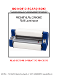
OPERATING INSTRUCTIONS MIGHTYLAM 2700 ROLL LAMINATOR abcoffice 800-658-8788 www.abcoffice.com abcoffice 800-658-8788 www.abcoffice.com TABLE OF CONTENTS Safety Messages and Electrical Safeguards ..............................1-2 Introduction .................................................................................2-3 Laminator Features .................................................................3 Specifications ...................................................................................3 Intial Set-up ..................................................................................4-5 Unpacking ...............................................................................4 Components .........................................................................4-5 Operation ......................................................................................5-8 Loading Laminating Film .......................................................5 Threading Laminating Film ..................................................6-7 Adjusting Mandrel/Film Tension.............................................7 Heat Shoe Temperature ...........................................................8 Adjusting Slitter Blades ...............................................................8-9 Laminating ..................................................................................9-11 Coating Mount Board.............................................................10 Mounting & Laminating.........................................................11 Troubleshooting ........................................................................12-13 Maintenance ..............................................................................13-14 Cleaning Heat Shoes & Rollers .......................................13-14 Removing Wrap-Arounds......................................................14 Warranty & Return Policy ...........................................................14 Parts List ....................................................................................15-17 Parts Illustrations ......................................................................18-21 Exploded View .......................................................................18 Side Panels ........................................................................19-20 Wiring Diagram.......................................................................21 abcoffice 800-658-8788 www.abcoffice.com abcoffice 800-658-8788 www.abcoffice.com IMPORTANT SAFETY MESSAGES AND ELECTRICAL SAFEGUARDS For your protection, do not connect the laminator to electrical power or attempt to operate it until you read these instructions completely. Keep these instructions in a convenient location for future reference. This instruction manual and labels affixed to the laminator are important safety messages. Read these messages carefully. For your safety... Save these Operating Instructions for later use. Keep hands, long hair, clothing, and other loose articles such as jewelry and ties, away from laminator’s moving parts. Do not touch the heat shoes while the laminator power is turned on. Allow shoes to cool completely before touching. Do not use the laminator for other than its intended purpose. Place laminator on a sturdy cart, stand, or table. A laminator placed on an unstable surface may fall, causing serious bodily injury. Move laminator with caution. Quick stops, excessive force, or uneven floor surfaces may cause the laminator and cart to overturn. Never insert objects or spill liquids in or on the laminator. They may contact dangerous voltage points or short out components that could result in fire or electrical shock. The laminator should only be operated from the type of power source indicated in these Operating Instructions and on the data plate located on the rear panel of the laminator. The three-pronged grounding plug is a safety feature and will only fit into a grounding-type power outlet. If you are unable to insert the plug into an outlet contact a qualified electrician to have a suitable outlet installed. Do not leave the laminator power on overnight. Unplug the laminator at the end of the day. abcoffice 1 800-658-8788 www.abcoffice.com Unplug the laminator before moving it or when it is not in use for an extended period of time as a precaution against the possibility of an internal malfunction that could create a fire hazard. Do not operate the laminator with a damaged power supply cord or plug, or after it malfunctions or has been damaged in any manner. Keep the power cord away from hot or wet surfaces. Do not overload electrical outlets beyond their capacity as this can result in fire or electrical shock. This unit is rated at 15 amps and should be the only item plugged into a 15 amp branch circuit. When connected to a 20 amp branch circuit any items in addition to the ML27 must not exceed 4 amps. Adjust only those controls that are specified in these Operating Instructions. Do not attempt to service or repair the laminator yourself. Unplug the laminator from the electrical outlet and contact an authorized service representative under any of the following conditions: • When the power supply cord or plug is damaged or frayed. • If liquid has been spilled into the laminator or it has been exposed to water. • If the laminator has been subjected to excessive jarring through being dropped or bumped. • If the laminator does not operate normally when following the operating instructions. • KEEP THE LAMINATOR OUT OF THE REACH OF CHILDREN. INTRODUCTION Congratulations on your purchase of the ML27 Roll Laminator. This unit is designed to provide years of trouble-free service. The ML27 will accept rolls of laminating film up to 27” wide in all film thicknesses. Paper and card stock up to 1/16” (1.6mm) thick may be laminated without adjusting the rollers. abcoffice 2 800-658-8788 www.abcoffice.com Your ML27 is preset at the factory for most applications so any adjustments should be minor. A LCD readout provides continual indication of the Heat Shoe temperature which may be adjusted as needed. Laminator Standard Features... Preset laminating roller pressure and speed require no adjustment. Feed table with adjustable guide. LCD readout for ease in monitoring temperature. Teflon® coated Heat Shoes for easy cleaning. Laminating film widths up to 27” (68.6cm). Total material thickness up to 3/16” (4.8mm) with roller adjustment. SPECIFICATIONS Plastic Width 27” (68.6cm) Plastic Thickness 1.5 mil up to 10mil (37 to 250 micron) Maximum Roll Length 1.5 mil - 1,000 feet (304.8 meters) 3 mil - 500 feet (152.4 meters) 5 mil - 250 feet (76.2 meters) 10 mil - 100 feet (30.5 meters) Speed 0-10 feet per minute (3m/minute) Net weight 97.5lbs (44kg) Power Requirements 120VAC, 60Hz, 1800 watts 220VAC available abcoffice 3 800-658-8788 www.abcoffice.com INITIAL SETUP Unpacking... Before unpacking the unit, inspect the shipping container for signs of damage. Notify the carrier and your dealer immediately if any damage is noted. CAUTION! The laminator, weighs approximately 98lbs. Use two people when removing the laminator from the shipping container. Components... Figure 1 below shows the location of the major components and controls of the ML27. You should become familiar with these before operating the laminator. Figure 1 abcoffice 4 800-658-8788 www.abcoffice.com Motor Switch: This switch controls power to the Laminating Rollers. If the switch is pressed to the FWD (light will come on) position the rollers move forward, pulling the plastic film and laminated material past the Heat Shoes. Reverse Switch: This toggle switch is found on the back of the machine. When this switch is pressed to the reverse position and the motor switch is on, the rollers move in the reverse direction. This is useful for clearing film from the rollers. Fan Switch: This switch turns the fans on and off. (Switch will be lighted when the fans are on). Heater Switch: This switch turns power to the top and bottom Heat Shoes on and off. (Switch will be lighted when the heaters are on). Heat Indicator: This light goes on when the Heat Switch is first turned on then remains on until the Heat Shoe reaches the operating temperature. After that point, the light will flash periodically as the thermostat controls the Heat Shoe temperature. OPERATION This section describes the operation of your ML27. This laminator is designed for all widths of plastic up to 27”. However, if narrower widths are used the Heat Shoes must be cleaned before using a wider roll. Refer to the MAINTENANCE section for cleaning instructions. Loading Laminating Film onto Mandrels... Slide the film onto the mandrel as in figure 2 below. Note that one mandrel is labeled TOP and the other BOTT (for bottom). They are not interchangeable. Figure 2 abcoffice 5 800-658-8788 www.abcoffice.com Threading Laminating Film... These instructions apply to poly-in film rolls (shiny side out, dull side in). 1. For the top supply roll place the mandrel ends into the slots in the top of the laminator. If you are facing the front of the laminator the film should unwind toward you from the bottom of the roll as in figure 3 below. Figure 3 2. Pull 6”-12” of film from the top roll. Pass the film under the idler bar, heat shield and over the heat shoes. Make sure the shiny side of the film is against the shoes. See figure 5&6 be low. 3. For the bottom supply roll, remove the feed table. Place the mandrel ends into position in the lower mandrel holder slots. If you are facing the front of the laminator the film should unwind away from you from the bottom of the rollers as shown in figure 4 below. Figure 4 4. Pull 6”-12” of film from the bottom roll. Pass it under the lower idler bar. You can “dropdown” the lower idler bar to give you more clearance. After doing so, return the idler bar to its upper position for running the machine. Drape the film from the bottom roll over the film from the top roll. See figures 5&6 below. NOTE: The shiny side of the film must always go against the Heat Shoes. CAUTION! The Heat Shoes reach a temperature of up to 350°F. Do not touch the surface of the Heat Shoes. Figure 5 Figure 6 abcoffice 6 800-658-8788 www.abcoffice.com 5. Turn the Motor Switch on to start the Laminating and Pull Rollers. 6. Feed a piece of thin cardboard about 10” x 25” against the film so that it is centered between the two Heat Shoes. Push the cardboard and film into the Laminating Rollers. See figure 5. Watch cardboard pass through the back (pull) rollers to avoid a wrap-aound. 7. When the feed card has completely exited the Pull Rollers at the rear of the laminator turn the Motor Switch off. 8. Replace the feed table. 9. If you are ready to laminate, the Heat Switch should be in the on position and the Heat Indi cator should have gone off. Adjusting Mandrel/Film Tension... Each type of laminating film has different characteristics and may require laminator adjust ment. The tension should be set so that the film moves over the Heat Shoes without wrinkles as the film enters the laminator. Best results are obtained if tension adjustments are made while the unit is at operating temperature. If any adjustments are required use the following procedure: 1. Switch the Heaters on. Wait for the Heat Shoes to reach operating temperature. The Heat Indicator will go off when the proper temperature is reached. You can check the temperature by reading the thermometer located on the right side of the laminator. 2. Press the Motor switch to on. 3. Locate the knob on the right side of the Top Supply Mandrel. See Figure 7 below. Turn the knob to adjust the tension (clockwise to increase, counter clockwise to decrease) until the film passes over the Top Heat Shoe without wrinkles and the web between the Laminating and Pull Rollers is tight. Note: This adjustment requires only a few degrees of turn. If the knob is turned too far, you may stall the drive motor. Figure 7 4. If necessary locate the knob on the right side of the bottom Supply Mandrel and adjust the tension as in step 3 above. 5. If you are not ready to laminate, turn the Motor Switch and Heat Switch off. 7 abcoffice 800-658-8788 www.abcoffice.com Setting Heat Shoe Temperature... The laminator temperature should be adjusted according to the film thickness and the item being laminated. See table 1 below for recommended temperature settings. Keep in mind that the temperatures listed are approximate and different brands of laminating film and heavy paper stocks may require different temperatures. Also keep in mind that when the machine is cold the warm-up time may be longer than the heat indicator light may suggest due to the rollers not yet having sufficient heat distribution. 1. Turn the Heater Switch on. 2. Use the heater Thermostat Adjustment Knob on the left side of the laminator to adjust the temperature of the Heat Shoes. Use the temperatures in table 1 below as a guide. Material Temperature Range 1.5 mil (.0015”) 270°F - 325°F 3 mil (.003”) 240°F - 275°F 5 mil (.005”) 250°F - 270°F 10 mil (.010”) 250°F - 270°F 3. Turn the knob counter clockwise to reduce the temperature and clockwise to increase the temperature. If reducing the temperature, wait several minutes for the heat to drop to the desired operating temperature. When increasing temperature, the indicator lamp will come on as the laminator is heating up and go off when it reaches the set temperature. 4. Check the LCD readout to see if the desired temperature has been reached. You may have to make a few minor adjustments before optimum temperature is set. Adjusting Slitter Blades The slitter (figure 8) may be set to trim the web to the desired width as it exits the laminator. If an additional slitter blade is installed (optional), two pages (side-by-side) may be laminated and trimmed in a single operation. As the web exits the unit, these pages may then be separated with the additional slitter blade. abcoffice 8 800-658-8788 www.abcoffice.com Caution! If the blade release knobs are turned too far, the slitter blade may fall out of its guide and come in contact with the rubber rollers. If this happens, the rollers could be damaged. Never turn the blade release knobs more than one turn to position the blades. To adjust the slitter blades: 1. Be sure the slitter blades are positioned above the laminating web. If they are lowered, loosen the release knobs and lift the blades away from the web. Tighten the knobs to lock the blades in place. 2. Loosen the positioning knobs (counter clockwise) and slide the slitter blades left or right to the desired width of the edge seal. Lock the blades left or right to desired position by turning the positioning knobs (clockwise). 3. Carefully, loosen each release knob and lower the blade in contact with the web. Tighten the release knob. 4. To prevent accidental damage to rollers, remove slitter blades when not in use. Figure 8 Laminating 1. Be sure the heaters have been turned on and are at the proper temperature. The fans should be turned on for laminating 3mil and heavier. Caution! Do not allow the temperature to exceed 350°F as this could cause the laminating film to melt on the Heat Shoes. 2. Adjust the Paper Guide on the Feed Table so that the right edge of the item will enter the laminator at the desired position. 3. Press the Motor Switch to the on position. The film will begin moving through the laminator. 4. After clear laminating film exits the Pull Rollers at the rear of the machine you may slide the first item to be laminated into the laminator with the right edge along the Paper Guide. abcoffice 9 800-658-8788 www.abcoffice.com Note: You may want to run a test lamination first as any item that passes between the Heat Shoes will be laminated and cannot be recovered until it exits the rear of the laminator 5. Additional items may be fed in sequence, keeping enough distance between sheets for trim ming. 6. After the last item has exited the Pull Rollers, turn the Motor Switch off. 7. Use the Zippy Cutter to cut across the film to remove the laminated items from the unit. Coating Mount Board The ML27 is capable of applying an adhesive coating on up to 3/16” uncoated mount board. 1. Load a roll of adhesive, with the liner wound to the outside, onto the top mandrel in the same manner as with laminating film. Thread the liner side of the adhesive over the top idler roller (so that the adhesive does not stick to the idler roller) and then through the laminator as with laminating film. 2. If the mount board is the same width as the roll of adhesive it is not necessary to load anything onto the bottom mandrel. If the mount board is narrower than the adhesive, load a roll of paper or film onto the bottom mandrel to keep the adhesive from accumulating on the rollers and heat shoes. Thread as for laminating film. 3. Using the supplied allen wrench back out the four pressure adjustment screws about 1/4” each. (Be sure to return the screws to their original position when going back to regular sheet laminating). 4. Turn heat switch to ON position if heat is needed for the application. 5. Set the temperature to the desired setting, depending upon the type of adhesive used. 6. Feed the uncoated mount board into the laminator behind a leader board of the same thickness. The leader board will prevent the compression of the leading edge of your mount board. 7. You may coat subsequent boards now, one directly behind the other, so that the board in front becomes the leader board. If at any time you have adhesive going through the machine without mountboard, be sure to pull the adhesive on the exit side of the machine to prevent a wrap-around. abcoffice 10 800-658-8788 www.abcoffice.com Mounting & Laminating The ML27 is capable of simultaneously mounting and laminating a print on up to 3/16” mount board. Preparing your print for mounting: 1. Peel back about 2” of release liner on your precoated mount board. 2. Align the top edge of your print with the top edge of the mount board (see figure 9). Mounting your print: 1. Be sure all laminator parts (i.e. safety shield, feed table, etc.) are in their proper positions and the laminating film is loaded correctly on top and bottom mandrels. (See page 7 for film loading instructions). 2. Using the supplied allen wrench back out the four pressure adjustment screws about 1/4” each. (Be sure to return the screws to their original position when going back to regular sheet laminating). 3. Turn the Heat Switch to the ON position. 4. Set the temperature using table 1 on page 10 as a guide. You may need higher temperatures than indicated for mounting and laminating mount board. 5. Turn the fans on. Figure 9 6. Perform a test mount to ensure proper settings for successful mounting. If any adjustments are necessary make them now and run another test. Repeat this step until you obtain desired results. 7. Feed the print and mount board slowly and evenly into the laminator behind a leader board so that the leading edge of your mount board does not become compressed. Pull back the peeled back release liner before it enters the rollers. 8. You may mount subsequent prints now, one directly behind the other so that the board in front becomes the leader board. 9. Once your last print has completely exited the laminator, turn the MOTOR and FAN switches OFF and use the trimmer to remove the mounted and laminated prints. abcoffice 11 800-658-8788 www.abcoffice.com TROUBLE SHOOTING The following guide will assist you with most problems that may be encountered when laminating. PROBLEM: Laminator is inoperative. Motor does not run, indicator lights are out. ACTION: Unit may be unplugged. Connect power supply. Ensure that your circuit breaker has not tripped. Fuse may have blown. Replace fuse (back next to power cord) with 15amp BUSS (MDA-15). PROBLEM: Laminating film and item being laminated move through laminator erratically. ACTION: Check thickness of item to be laminated. Maximum thickness is 1/16” (1.6mm) if rollers have not been adjusted. Clean heat shoes of residual adhesive. Refer to MAINTENANCE section for cleaning instructions. PROBLEM: Plastic is not bonding to the item or to itself at the edges. ACTION: Make sure heat shoes and rollers are at proper operating temperature and have had time to warm up. See table 1 for the suggested temperature ranges. PROBLEM: Wrinkles appear on the laminated items running parallel with the outside edges. ACTION: Increase roller tension on top and/or bottom supply rolls. Reduce heat shoe temperature. Clean heat shoes of residual adhesive. See MAINTENANCE section for cleaning instructions. abcoffice 12 800-658-8788 www.abcoffice.com PROBLEM: Blistering of the film appears over the item or along the edge. ACTION: Reduce temperature on one or both heat shoes. If the indicator light remains on after the adjustment is made, disconnect the power supply and contact your dealer. Clean laminating rollers. See MAINTENANCE section for cleaning instructions There may be moisture in the paper you are laminating. Store paper in a dry place and be sure that any ink is thoroughly dry before laminating. PROBLEM: Laminated material curls after leaving pull rollers. ACTION: Adjust tension. If laminated item curls upwards, reduce top roller tension. If item curls downward, reduce bottom roller tension. Clean heat shoes of residual adhesives as it may be causing “drag” on one side. Refer to MAINTENANCE section for cleaning instructions. MAINTENANCE This section contains instructions for cleaning and maintaining your laminator. These procedures should be preformed at regular intervals to help ensure the trouble-free operation of your laminator. Cleaning the Heat Shoes and Laminating Rollers... The Heat Shoes and Laminating Rollers should be cleaned of any residual adhesive whenever the film does not pass smoothly over their surfaces. NOTE: The surface of the heat shoes is Teflon coated and must only be cleaned using a soft cloth. The Heat Shoes can easily be damaged by sharp or abrasive objects. 1. Allow the Heat Shoes to cool. 2. Remove the Feed Table. 3. Cut the plastic film at the top and bottom mandrels. 4. Turn the Motor Switch on and pull the film out of the back of the machine. 5. Turn the Motor Switch off. abcoffice 13 800-658-8788 www.abcoffice.com 6. Use a soft cloth moisentened with alcohol to remove any residue from the Teflon surface of the Heat Shoes and Laminating Rollers. 7. Allow the Heat Shoes and Laminating Rollers to dry before re-threading the film. Removing Wrap-arounds... When laminating with thinner gauges of film, there is the possibility of the film wrapping around the Pull Rollers. Use the same procedure for Cleaning the Heat Shoes and Laminating Rollers in order to remove a wrap-around. If the film cannot be pulled out of the back of the machine... leave the motor and switch on and use the reverse switch on the back of the machine to reverse the rollers so the film can be pulled up and out of the machine. NOTE: The Heat Shoes are hot! Use caution when cleaning the rollers or heat shoes, or when removing wrap-arounds. WARRANTY AND RETURN POLICY Warranty Your laminator is warranted to be free of defects in material and workmanship for a period of 1 year from the original purchase date. In the event of a defect in material or workmanship, the manufacturer or its authorized dealer, will repair or replace (at their option) the laminator. This does not cover rollers that have been damaged due to improper usage. The manufacturer makes no other warranty stated or implied except as stated above. Return Policy If your laminator is not operating properly, first review the Operating Instructions and Troubleshooting Guide. If the malfunction cannot be corrected, contact your local dealer for instructions. Be sure to have your machine serial number and date of purchase handy. If the laminator must be returned to the dealer, proper packaging and freight charges are your responsibility. Shipping damages as a result of improper packaging is not covered under the terms of this warranty. abcoffice 800-658-8788 14 www.abcoffice.com PARTS LIST AND ILLUSTRATIONS This section contains reference drawings and a parts list to assist you when ordering parts for your laminator. The drawings show only those parts that may be replaced by the dealer. Item 1 2 3 4 5 6 7 8 9 10 11 12 13 14 15 16 17 18 19 20 21 22 23 24 25 26 27 28 29 30 31 32 33 34 35 abcoffice Part Number 10091 10092 10093 10095 10096 10033 10100 10101 10102 10103 10104 10105 10106 10108 10110 10111 10343 10113 10114 10115 10116 10117 10118 10119 10120 10121 10129 10130 10125 10126 10128 10085 1395 541 1172 Description C-Clip, 15/16” DIA Bushing, 5/8 x 3/4 x 1 1/4 Knob, 1/4-20 x 1 1/4 long Cap, end Spring, brake adjustment Switch, green, round Hub, brake, mandrel Mandrel, supply, top Gripper, core, mandrel Table, feed, ezlam II Cover, heater, ezII Holder, glass, heat shield Bar, tie, ezII Cover, rear, ezII Shoe, heat, ezII Glass, heat shield, ezII Cover, roller, ezII, new Holder, roller bushing Rod, idler, top ezII Rod, idler, bottom ezII Support, front, feed table Support, rear, feed table Mount, heat shoe ezII Tubing, roller, idler Roller, top, front Roller, bottom, front Roller, top, back Roller, bottom, back Axle, gripper Holder, bottom, roller bush Mandrel, supply, bottom Motor, ezII, 80mm Cord, power 14-3 Terminal block, 6 station Fuse holder, HTB-34i 15 800-658-8788 Qty 2 8 2 4 2 3 2 1 2 1 1 1 2 1 2 1 1 4 1 1 1 2 8 2 1 1 1 1 2 4 1 1 1 2 1 www.abcoffice.com 36 37 38 39 40 41 42 44 45 46 47 48 49 51 52 53 54 55 56 57 58 59 60 61 62 63 64 65 66 67 69 70 71 72 73 74 75 76 78 abcoffice 1170 1182 10509 8288 10500 10505 10504 10232 10393 10394 10303 10304 10318 8107 4369 134 1270 1294 1319 10324 524 555 560 573 Zipcut 1263 557 10322 10323 10325 10327 10330 10333 10337 10340 10341 10349 10350 530 Feet, rubber, large Fuse, 15amp, MDA-15 Heater, 120v, 290w, mightylam Relay, solid state, 25A, DC Sprocket, motor, mightylam Sprocket, front, mightylam Sprocket, rear, mightylam Switch, motor reverse EZII Cover, side, left Cover, side, right Support, side, left-mold Support, side, right-mold Label, EZII Alum rod, thermostat Label, increase Test sheet, roll lams Label, “caution hot” Label, loading inst. Light, indicator, red 120v Chain, roller drive, EZII Strain relief bushing lge Thermostat, roll lam Thermostat, HTU-428 (EZ) Thermostat, mount Zippy cutter, stock# K353 Knob, feed table guide Knob, thermostat Guide, feed table, EZII Nut, locking, feed table Block, idler sprocket Set screw, modified, EZII Sprocket, idler, EZII Bushing, supply mandrel Spring, roller, EZII Screw, 4-40 x 5/16 BHCS Guard, hole, EZII Rectifier, EZII Bolt, shoulder, 1/4 x 1/2 Wire, 18 GA, green, EZII 16 800-658-8788 4 1 6 1 1 1 1 1 1 1 1 1 1 1 1 1 1 1 2 1 1 1 1 1 1 2 2 1 2 1 4 1 2 4 5 2 1 1 2 www.abcoffice.com 79 80 81 82 83 84 85 86 87 88 89 91 92 93 94 95 96 97 98 99 100 101 102 103 104 105 106 107 108 109 110 111 112 113 114 115 abcoffice 10354 10355 10357 547 1459 10359 2501 700562 2661 2201 10370 8358 1366 2659 503 2504 10365 10356 10368 10363 10364 574 10124 1060 2856 827208 10386 10387 10389 10090 10361 4031 10390 10391 587 588 Spring, thermometer, EZII Screw, cover, EZII Block, terminal, 10 STA Terminal ring blue Screw, set, 10-24 x 1/4” Screw, 6-32 x 1”” PHIL. Screw, 6-32 x 3/4” Nut, 6-32 w/nylon insert Screw, 1/4-20 x 3/4” P.H. Screw, 6-32 x 1/2” Screw, set, 10-32 x 1 Screw, 10-24 x 1 PH Nut, 10-24, nylon lock Screw, 1/4-20 x 2” P.H. Spacer washer Screw, 8-32 x 2 1/2 Screw, set, 1/4-20 x 1/4 Sink, heat, EZII Insert, supply mandrel Nut, lock, nylon, 10-32 Washer, fender, #10 x 1 1/4 Variable speed control*PS Control, heat, finishers Bushing, idle bar Shaft collar, FR12, 1/2” Box and inserts, EZII Key, hex, 3/16” x 6” long Label, mightylam temp Label, mightylam Fan, cooling, 120v, EZII Guard, fan, mightylam Digital read out (new) Backing, idler, block, EZII Tubing, teflon, black Wire, 14 gauge, black Wire, 14 gauge, white 17 800-658-8788 1 10 1 8 4 2 2 8 12 4 2 2 2 4 4 1 1 1 4 4 4 1 1 4 2 1 1 1 1 7 7 1 1 .083 6.125 3.25 www.abcoffice.com 116 117 118 119 120 121 122 123 124 125 126 127 128 129 130 131 132 abcoffice 589 598 7125 596 1326 597 593 10392 10406 10407 8279 4266 394 1457 2200 2830 10234 Wire, 18 gauge, black Wire, 18 AWG, white/red Wire, 18 AWG, white/violet Wire, 18 AWG, white w/blue Wire, 18 AWG, white/black Wire, 18 gauge, white Wire, 18 gauge, red Housing, fan, bottom Label, bottom mandrel Label, top mandrel Sensor, k type Body, holder, blade Slitter assembly, roll Screw, 10-24 x 1/2” Screw, 5/16-18 x 5/8” Screw, 6-32 x 3/4”, flat Channel, board mount 18 800-658-8788 6.917 3.917 4.417 1.292 3.833 2 1.875 1 1 1 1 2 2 2 4 28 1 www.abcoffice.com abcoffice 800-658-8788 19 www.abcoffice.com abcoffice 800-658-8788 20 www.abcoffice.com abcoffice 800-658-8788 21 www.abcoffice.com abcoffice 800-658-8788 www.abcoffice.com