1
A sealed system central heating
and mains pressure hot water
supply appliance with thermal
store designed specifically for use
with solar energy
Design, Installation
& Servicing
Instructions Addendum
These instructions must be read in conjunction with the
standard Boilermate A-Class SP Design, installation and
servicing instructions before installation
Model Numbers
BMA 200 SP-SOL
BMA 220 SP-SOL
BMA 240 SP-SOL
BMA 260 SP-SOL
BMA 280 SP-SOL
BMA 300 SP-SOL
All models comply with the water heater manufacturers
specification for integrated thermal stores
ISSUE 5: 06-08
ISSUE 5: 06-08
Section
Page
DESIGN
Introduction Technical Data
3
5
INSTALLATION
Wiring Details
Typical Pipework Arrangement
Controls
Filling/Commissioning
Short Parts List
10
12
13
16
17
22
Terms & Conditions
The code of practice for the installation,
commissioning & servicing of central heating systems
Building Regulations and Benchmark Commissioning
The Building Regulations (England & Wales) require that the installation of a heating
appliance be notified to the relevant Local Authority Building Control Department.
From 1st April 2005 this can be achieved via a Competent Person Self Certification
Scheme as an option to notifying the Local Authority directly. Similar arrangements
will follow for Scotland and will apply in Northern Ireland from 1st January 06.
CORGI operates a Self Certification Scheme for gas heating appliances.
These arrangements represent a change from the situation whereby compliance with
the Building Regulations was accepted if the Benchmark Logbook was completed and
this was then left on site with the customer).
With the introduction of a self certification scheme, the Benchmark Logbook is being
replaced by a similar document in the form of a commissioning check list and a service
interval record is included with all gas appliance manuals. However, the relevant
Benchmark Logbook is still being included with all Thermal Storage products and
unvented cylinders.
Gledhill fully supports the Benchmark aims to improve the standards of installation
and commissioning of central heating systems in the UK and to encourage the regular
servicing of all central heating systems to ensure safety and efficiency.
Building Regulations require that the heating installation should comply with the
manufacturer’s instructions. It is therefore important that the commissioning check
list is completed by the competent installer. This check list only applies to installations
in dwellings or some related structures.
Page The Gledhill BoilerMate range is a WBS
listed product and complies with the WMA
Specification for integrated thermal storage
products. The principle was developed in
conjunction with British Gas. This product
is manufactured under an ISO 9001:2000
Quality System audited by BSI.
Patents Pending
The Gledhill Group’s first priority is to give a
high quality service to our customers.
Quality is built into every Gledhill product
and we hope you get satisfactory service
from Gledhill.
If not please let us know.
DESIGN
T1
F&E cisterns
Components fitted
within the
appliance case
PRV
Discharge pipe
Commissioning/
filling assembly
Solar
Controls
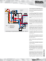
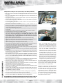
The arrangement of a typical BoilerMate A-Class
SP Solar installation is shown schematically
below. The basic unit which is covered by these
instructions incorporates the Danfoss SH - E01
solar controller.
S1/S2
T3
Solar
circuit
S4
Hot out
Mains
cold in
BoilerMate
A-Class SP Sol
S3
S6
Heating/hot
water controls
(ACB)
Automatic
bypass
valve
S5
T2
V2
Heating
circuit
V1
Note:
Sealed
system kit available as
an optional
extra
V1- normally open
(powered closed)
V2- normally closed
(spring return)
Boiler
Schematic Diagram of Typical BoilerMate 260 SP solar system Figure 1.1
The appliance generally follows the principles
of the standard BoilerMate A-Class SP appliance
but is fitted with a separate set of coils to
allow it to accept the maximum amount of
heat available from the solar panels/controls.
This is then used to supplement the hot water
system.
Because this product does not require a safety
discharge from a temperature and pressure
relief valve, any installations will be easy to
incorporate into the building and will not suffer
from the problems associated with using PVCu
soil stacks to take the discharge from unvented
cylinders.
The models 200 and 220 are supplied with a
single F&E cistern. All four larger models are
supplied with two F&E cisterns.The single cistern
will fit within the cupboard in a typical storey
height cupboard but when two cisterns are
used, these will need to be located elsewhere.
The operation of the appliance/solar system is
controlled by a number of sensors. The location
and reference numbers of the various sensors
is shown eg 2, S6.
Sensors S1/S2, S3, S4, S5 and S6 are connected
to the appliance control PCB which operates all
the heating and hot water functions as the basic
BoilerMate appliance.
Sensors T1, T2 and T3 are connected to the
Danfoss controller and operate all the solar
functions.
Sensor T3 provides a high temperature interlock
to de-activate the solar pump at a temperature
of 90°C in the store.
Although sensors T3 and T2 are wired in to the
solar controller the cable provided for Sensor T1
(3 metres long) may require to be extended by
the installer dependant on the location of the
solar panels/appliance. (2 x 0.75mm2 double
insulated cable) up to a maximum total length
of 50 metres.
A safety device (pressure relief valve) to control
the risk of over-pressure in system components
should be fitted as shown on the Solar System
diagram. A termination from a safety pressure
device should minimise the risk of damage
to persons or materials. Suitable locations are
a high temperature receptacle, an internal
Page INTRODUCTION
Solar
collector
DESIGN
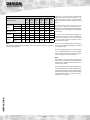
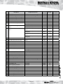
Model Selection Data Table/Weights
BMA
200 SP
SOL
BMA
220 SP
SOL
BMA
240 SP
SOL
BMA
260 SP
SOL
BMA
280 SP
SOL
BMA
300 SP
SOL
2-3
2-4
3-5
3-5
4-5
5-6
1
2
2
2
2
3
2
1
2
3
3
3
(m2)
80
100
130
170
220
280
Empty
(kg)
73
79
96
104
112
120
Full
(kg)
233
260
313
366
411
472
Total
(l)
160
181
217
262
299
352
Solar
(l)
82
93
109
127
148
167
Model Reference
Bedrooms
Dwelling
Bathrooms
type
En-Suite
Max Floor Area
Weight
Volume
Note:
It is important that the maximum floor area is not exceeded to achieve compliance
with the SAP regulations.
gulley or else issue externally at ground level.
High level termination from walls or on roofs
could cause injury to people or animals below
if the valve were to release scalding water and
steam.
The pipe leading to the safety device and
the collector should be of rigid and nondeformable construction, without any possibility
of restriction or disclosure by any other fitted
component.
In order to meet the Building Regulations
requirement to reduce the rate of accumulation
of scale in hard water areas, it is important
that the installer checks the hardness of the
incoming water supply.
If this exceeds 200ppm (mg/l), we recommend
that the factory fitted scale inhibitor is ordered
as an optional extra.
If it exceeds 300ppm (mg/l), we recommend the
use of a polyphosphate type of scale inhibitor.
This can also be ordered as an optional extra but
will need fitting on site by the installer.
Note:
If the summer towel rail circuit is required, this
will need to be a separate zoned circuit from the
heating circuit complete with its own time and
temperature controls.
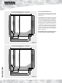
INTRODUCTION
The standard manual fill model BoilerMate AClass SP SOL appliance is shown. A ballvalve and
overflow are available as an optional extra at the
time of order. If required, these should be fitted
in the plain F&E cistern in a position to suit the
individual site conditions.
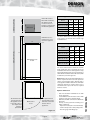
Page DESIGN
F&E cistern
*500
300
*250
BMA 200-220 SP SOL
Appliance Dimensions
B
*If the F&E cistern is
fitted with a ballvalve,
this dimension will
need to increase to
350mm to comply with
the Water Regulations.
*Minimum access /
maintenance access
above the appliance
case.
Model
Height
(A)
Width
(B)
Depth
(C)
BMA 200-SP SOL
1330
560
620
BMA 220-SP SOL
1330
560
620
BMA 240-SP SOL
1575
560
620
BMA 260-SP SOL
1575
610
670
BMA 280-SP SOL
1575
640
700
BMA 300-SP SOL
1485
710
770
The above dimensions are for the appliance
only and do not include the 100mm high
installation base.
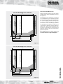
Minimum Cupboard Dimensions
A
D
BMA 240-300 SP SOL
Model
BoilerMate A-Class
SP SOL
Height Width
(D)
(E)
Depth
(F)
BMA 200-SP SOL
1980
660
630
BMA 220-SP SOL
1980
660
630
BMA 240-SP SOL
2175
660
630
BMA 260-SP SOL
2175
710
680
BMA 280-SP SOL
2175
740
710
BMA 300-SP SOL
2085
810
780
100
The above dimensions include the 100mm
high installation base and allow space for
installation/maintenance of the appliance only.
The height shown for the 200-220 models also
allows for the installation of the F&E cistern (with
no ballvalve) as shown opposite.
Note: With the 240-300 models, additional space
will be required for two feed and expansion
cisterns (each 280mm wide x 420mm deep x
300 high). This is NOT included in the minimum
cupboard dimensions shown above. Access
and maintenance space will also be required
for these cisterns.
F
C
E
The minimum clear
opening in front of
the appliance to be
at least the same as
the depth of the
appliance
plus 50mm.
Maintenance
access
The cupboard door
opening will need to
take into account the
various sizes of
appliances.
Figure 1.2
Page • Hot and cold water manifolds for use with
plastic pipework.
• Scale inhibitor for mains water services with
hardness levels above 200ppm (mg/l).
• Ballvalve/overflow connector for automatic
fill model.
• Primary sealed system kit for fitting near
boiler comprising:
- Expansion vessel (size varies with model)
- 15mm 3 bar pressure relief (safety) valve
- Pressure gauge and filling loop
TECHNICAL DATA
Options at Extra Cost
DESIGN
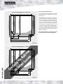
Connection Details/Dimensions
Connection Details/Dimensions - 200 model
Diagrams opposite show the connection details
and dimensions for the BoilerMate A-Class SP
SOL appliance.
70
520 - Domestic Hot Water
545 - Incoming Cold Supply
560 - Combined Boiler/Heating Return
525 - Heating Flow
490 - Boiler Flow
620 (including the door/clock)
560
Note: All dimensions are shown in mm and
are to the centre line of pipework/gland.
130
210
490
520
Figure 1.3
Connection Details/Dimensions - 220 model
70
520 - Domestic Hot Water
545 - Incoming Cold Supply
560 - Combined Boiler/Heating Return
525 - Heating Flow
490 - Boiler Flow
620 (including the door/clock)
560
TECHNICAL DATA
The BoilerMate A-Class SP SOL units are supplied
on an installation base to allow the pipe runs
to connect to the appliance from any direction.
It is easier if all pipes protrude vertically in the
cut out area shown. Compression or push fit
connections can be used. All pipe positions
are approximate and subject to a tolerance of
+/-20mm in any direction. A 15mm cold water
supply and a 22mm warning/overflow pipe
may also be required for the separate feed and
expansion cisterns if these are located in the
appliance cupboard.
130
210
490
520
Figure 1.4
Page DESIGN
Connection Details/Dimensions
Connection Details/Dimensions - 240 model
Diagrams opposite show the connection details
and dimensions for the BoilerMate A-Class SP
SOL appliance.
70
520 - Domestic Hot Water
545 - Incoming Cold Supply
560 - Combined Boiler/Heating Return
490 - Boiler Flow
525 - Heating Flow
620 (including the door/clock)
560
The BoilerMate A-Class SP SOL units are supplied
on an installation base to allow the pipe runs
to connect to the appliance from any direction.
It is easier if all pipes protrude vertically in the
cut out area shown. Compression or push fit
connections can be used. All pipe positions
are approximate and subject to a tolerance of
+/-20mm in any direction. A 15mm cold water
supply and a 22mm warning/overflow pipe
may also be required for the separate feed and
expansion cisterns if these are located in the
appliance cupboard.
Note: All dimensions are shown in mm and
are to the centre line of pipework/gland.
130
210
490
520
Figure 1.5
Connection Details/Dimensions - 260 model
600 - Domestic Hot Water
615 - Incoming Cold Supply
130
240
510
550
Figure 1.6
Page TECHNICAL DATA
50
625 - Combined Boiler/Heating Return
535 - Boiler Flow
595 - Heating Flow
670 (including the door/clock)
610
DESIGN
Connection Details/Dimensions
Connection Details/Dimensions - 280 model
Diagrams opposite show the connection details
and dimensions for the BoilerMate A-Class SP
SOL appliance.
60
605 - Domestic Hot Water
610 - Incoming Cold Supply
650 - Combined Boiler/Heating Return
605 - Heating Flow
570 - Boiler Flow
700 (including the door/clock)
640
Note: All dimensions are shown in mm and
are to the centre line of pipework/gland.
160
250
570
605
Figure 1.7
Connection Details/Dimensions - 300 model
000 - Domestic Hot Water
000 - Incoming Cold Supply
De
00
000 - Combined Boiler/Heating Return
000 - Heating Flow
000 - Boiler Flow
ta
in ils
la to
te f
r i ol
ss lo
ue w
770 (including the door/clock)
710
TECHNICAL DATA
The BoilerMate A-Class SP SOL units are supplied
on an installation base to allow the pipe runs
to connect to the appliance from any direction.
It is easier if all pipes protrude vertically in the
cut out area shown. Compression or push fit
connections can be used. All pipe positions
are approximate and subject to a tolerance of
+/-20mm in any direction. A 15mm cold water
supply and a 22mm warning/overflow pipe
may also be required for the separate feed and
expansion cisterns if these are located in the
appliance cupboard.
000
000
000
000
Figure 1.8
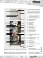
Page DESIGN
Standard Equipment
14
13
27
21
The standard configuration of the BoilerMate
A-Class SP SOL is shown opposite.The Appliance
Controllers mounted inside the appliance,
control the operation of the complete system.
These are pre-wired to a terminal strip where all
electrical connections terminate. It is supplied
with the following factory fitted equipment:1
2
36
26
33
3
34
32
30
31
11
35
19
28
4
11
23
25
8
5
11
7
1
2
16
11
10
22
24
6
18
11/12
29
20
9
15
17
3
4
5
6
7
8
9
10
11
12
13
14
15
16
17
18
19
20
21
22
23
24
25
26
27
28
29
30
31
32
33
34
35
36
37
Switch immersion heater (2 x 3kW elements & OHT’s)
Grundfos UPR 15-50 (185 & 215 model) or
15-60 boiler/central heating pump
Overheat (top) sensor pocket (Sensor S1/S2)
Middle sensor pocket (Sensor S6)
Bottom sensor pocket (Sensor S5)
DHW (CW) inlet sensor, S3
DHW outlet sensor, S4
Grundfos UPR 15-50 PHE pump
Filter & flow regulator
Plate heat exchanger
Isolating valves
Non return valve
Open vent/safety connection
Cold feed/expansion connection
CW inlet connection
HW outlet connection
Thermal store drain tapping
Return from PHE to store
Flow from store to PHE
Combined boiler/heating return
Primary flow manual air vent
Boiler flow (from boiler)
CH flow
2 port valve V1 (boiler flow)
2 port valve V2 (CH flow)
Solar heat exchanger return connection
to solar panel
Solar heat exchanger flow (collector)
connection from panel
Remote solar panel sensor (T1) & cable
Solar return sensor (T2)
Solar overheat sensor (T3)
Solar circuit pump UPS 15-60 (high temp.)
Solar controller
User control panel/clock
Appliance control board
Electrical DIN rail
Solar expansion vessel connection (fitted
with pressure gauge)
100mm high installation base
Optional Equipment
Figure 1.9
Note 1: All the panels, pipework and other components necessary for the installation
of the remainder of the solar system can be supplied by Gledhill with the BMA SP SOL
appliance. For further details please contact the Gledhill Technical Sales Dept.
Note 2: A single feed and expansion cistern will be supplied with the BMA 200 and 220
SP SOL appliances. Two feed and expansion cisterns will be supplied for other models.
Note 3: A solar commissioning/filling assembly is provided separately for fitting
vertically on site (see diagram on page 9 for more detail).
Page •
•
•
Hot and cold water manifolds for use with
plastic pipework (Set 1 or 2).
Electronic scale inhibitor for mains water
services with hardness levels above
200ppm (mg/l) fitted in the appliance.
Polyphosphate scale and corrosion inhibitor
for mains water services with hardness
levels above 300ppm (mg/l) for fitting on
site by the installer.
TECHNICAL DATA
37
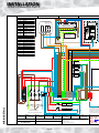
INSTALLATION
1
2
WIRE COLOUR LEGEND
Br
B
Brown
Black
Or
Orange
Y
Yellow
Wh
G/Y
White
Green / Yellow
Gr
Grey
G
Green
TWO CHANNEL DIGITAL CLOCK
CH
HOT
WATER ZONE 1
CH1
CH2
N
L
SCALE INHIBITOR
T1 COM T2
AL
P1
SOLAR CONTROLLER
DANFOSS SH - E01
P-SL
(PART No XB142)
ON
L
~
1
3
2
5
4
1
Solar Pump High Store
temperature interlock.
o
Capillary Thermostat set to 87 C
Cotherm GTLH0054
2
LN
SENSOR LEGEND
S1 & S2
Store overheat sensors
S3
Cold Water IN
S4
Domestic Hot Water OUT
S5
Bottom store sensor
S6
Middle store sensor
SPD1/2A
Red
Blue
4
1 2 3 4
R
Bl
3
OPTIONAL EXTRA
IF FITTED
3 Speed
Solar Pump
2K2 Resistor (Black)
ID_RESISTOR
A02
APPLIANCE ID
Normally
Open
Zone Valve
A
V1 HW B
Normally
Closed
Zone Valve
2
2.5 mm SID Silicone
A
2
2.5 mm SID Silicone
V2 CH B
2
2.5 mm SID Silicone
2
2.5 mm SID Silicone
2
2.5 mm SID Silicone
2
1
Br
3
Br
2.5 mm SID Silicon
2.5 mm SID Silicone
Br
2
4
3 WAY
E
SOL-T1
SOL-T1
VAL-V2
VAL-V1
VAL-SL2
VAL-N
VAL-PE
SL-F
VAL-N
SL-B
SL-R
SL-W
E
SL-H
E
L3
L2
L1
N
Remove link to fit room stat.
2
4.0 mm SIF Silicone
2.5 mm SIF Silicone
2
N
N
N
PE-IH
L-IH
BUS BAR
L
L-IH
N
R
R
N-IH
6A
2.5 mm SIF Silicone
A2
16A
MCB 3
E
16A
MCB 2
C1
MCB 1
2
A1
Bl
R
WIRING DETAILS
2
2 x 3kW Heating Elements
Mains Supply
230VAC 50Hz 32Amps
DRN.
DATE
03-03-08
DATE : MARCH 2008
Solar Sensor cable will
be extented to reach th
0.75mm2 two core flex
2 post junction box wil
fitted in the roof space
to the Solar panel senso
Bl
2
2.5 mm SIF Silicone
(10.00 mm² Twin & Earth Cable PVC)
S. McGachie
R
2
2.5 mm SIF Silicone
CH'KD.
SIGN.
S. Gataroa
DATE
03-03-08
ISSUE No : 4
APPROVED
Page 10
APP'D.
S. Gataora
SIGN.
DATE
03-03-08
DO NOT SCALE FROM THIS DRAWING. COPYRIGHT OF THIS DRAWING
IS RESERVED. IT IS NOT TO BE REPRODUCED COPIED OR DISCLOSED
TO A THIRD PARTY EITHER WHOLLY OR IN PART WITHOUT OUR
WRITTEN CONSENT.
© GLEDHILL WATER STORAGE LTD.
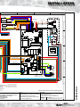
INSTALLATION
5
Duplex Sensor must be fitted in
top saftey overheat pocket
and secured
R
S1 & S2
S3
S5 & S6
Bl
Bl
R
Bl
Br
Wh
Br
Y
Y
Wh
Br
B
B
B
Wh
Br
O
O
Y
G
Br
Wh
Br
O
B
Y
Y
Bl
8
R
R
FRONT PANEL
Black Covering
2K2 A-ID A02
R
B
O
Flat Ribbon Cable
Or
Br
B
R
Or
Br
B
Red LED
B
'MODE'
Switch
B
J31
J9
Bl
A
Push Button
B
B
Br
Br
Duplex Sensor must fitted into S6
pocket i.e. above both V3 & V2 valves
T2 SOLAR
7
ID_RESISTOR
S4
Y
G
6
B
Green Neon Illuminated
ON / OFF Switch
R
Bl 1b
Dedicated Solar Zone Sensor
B
Br
J30
Br
O
I
1a
1 1b
1
Rocker Switch
terminal conections
B
Br
Bl
(Heating SL-H)
1a
J29
Wh
(Hot Water SL-W)
Or
(Room Stat SL-R)
B
J3
R
('SWITCH' ON / OFF)
Br
(Boiler ON / OFF)
C
J33
J28
G/Y
(Frost Protection SL-F) Y
J32
Bl
N
E
Br
(1) Connection only used
if Modulating Pump is fitted
need to
he panel,
and 5 amp
ll be required
close
or pocket.
Mod
DHW
Pump
E
Solar Collector Sensor fitted
in the panel sensor pocket
provided by manufacturer.
Minimum pocket size 8mm.
GLEDHILL WATER STORAGE LTD.
SYCAMORE TRADING ESTATE
SQUIRES GATE LANE
BLACKPOOL
LANCASHIRE
FY4 3RL
* All wire sizes 0.5mm² unless otherwise stated
TITLE
BOILERMATE 'A' Class SP SOL ADL1
With Danfoss Solar Controller
and three 2 port valves, factory fitted
2 channel digital clock.
JOB NAME
Electrical Schematic for :
BOILERMATE 'A' class SP SOL ADL1
Appliance fitted with 2 channel digital clock
DRG. SIZE
DRG. NAME
Page 11
A3
‘A’ Class BoilerMate SP SOL ver 4.ai
WIRING DETAILS
T1 Solar Sensor
Br
M
B
L
Bl
E
J5
N
G/Y
G/Y
D
Boiler
Pump
Bl
B
Br
3
Speed
M
L
J34
(1)
INSTALLATION
SOLAR PANEL TYPICAL CONNECTION DIAGRAM TO BOILERMATE SP SOL
Solar Panel
Sensor Cable
Junction Box
Collector
sensor T1
Internal Ceiling
PRV
No isolation valve should
be installed between the
solar circuit and the safety
valve (pressure reducing
valve).
Expansion
Vessel
60
40
80
20
100
120
0
1 bar
Temperature
Gauge and
Check Valve
FILL CONNECTION
DRAIN CONNECTION
OV /
CF /
Safety Expansion
l /min
13
1
6
4
8
2
Flow Meter
and Regulator
0.5 - 13 l/m
Roof Pitch
This component
arrangement is
provided with the
SOL appliance and
must be mounted
vertically on the
connection
provided.
10
0
Solar overheat sensor T3
Solar Controller
o
TYPICAL PIPEWORK ARRANGEMENT
82 C
Note:
No valves should be fitted
on the pipework between
the solar collector and
the Pressure Relief (Safety)
Valve (PRV).
Solar Return
Sensor T2
It is recommended that the
solar system is filled from the
connection points provided
using the solar filling
pump/tank available as an
optional extra.
Figure 1.10
Page 12
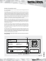
INSTALLATION
BoilerMate Heating/Hot Water Controls
The current BoilerMate A-Class SP Sol incorporates separate heating/hot water and
solar control systems.
The BoilerMate A-Class SP Sol heating and hot water controls operate in the same way
as the basic BoilerMate appliances but the single channel clock and the two rocker
switches have been replaced by a two channel digital clock. (Channel 1 controls the
gas boiler /hot water and Channel 2 the heating.) Details of how to set the clock are
shown in the user instructions which are provided in the plastic wallet fixed at the
bottom of the front panel. Recommendations regarding the setting of Channel 1 are
provided on the label adjacent to the front panel controls (see below). Channel 2
should be set as normal to control the heating on/off times required.
Label 1 - Channel 1 of this digital clock is dedicated to heating of the hot water. This
can be set to hold off the boiler during periods of potential high solar gain periods
eg 10.00 am to 16.00 pm allowing maximum solar contribution to the thermal store.
Central heating channel 2 will not be affected by holding off the boiler and operates
independently of channel 1.
If a high hot water demand is expected or the appliance runs out of hot water due to
poor solar gains, the setting of Channel 1 can be overridden which will bring on the
boiler and ensure hot water is made available. Dependant on use/weather, the ‘off’
times suggested above can be adjusted as necessary to ensure adequate amounts
of hot water are available.
The Switch 6kW electrical emergency back up system is fitted to this appliance. This
is switched on by moving the ‘mode’ rocker switch from normal to switch and is used
in the event of boiler failure. It is unlikely to be needed in Summer but can be used
in Winter as required to provide some heating and hot water in conjunction with the
solar input until the problem can be resolved.
It is an emergency only system and must not be used if the main system is
working correctly.
Red LED
BoilerMateA-CLASS SP Solar
14
16
18
20
22
24
+
Res.
+1h
PUSH BUTTON
Normal
Mode
Switch
0
Menu OK
To reset appliance
Label 1
See above for wording
Control circuit power
supply
Black button
Green rocker switch
(illuminated when on)
Figure 1.11
Page 13
CONTROLS
OFF:
SLOW FLASHING
MEDIUM FLASHING
RAPID FLASHING
ON:
1
2
3
4
5
6
7
Normal
Switch failure
Switch backup selected
Overheat safety trip
Switch on
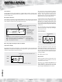
INSTALLATION
Solar Controls
The BoilerMate A-Class SP Sol appliance is supplied with a Danfoss electronic Solar
Heat Regulator ref SH-EO1 built into the appliance and the necessary temperature
sensors ref NTC 100k.
Description of function
The regulator controls the heat transmitted from the solar collector to the thermal
store using the temperature differential between the sensors fitted adjacent to the
solar collector and in the lower part of the thermal store.
LEDs
Green LED indicates the pump is running
Red LED indicates fault
AUTO
PUMP
INFO
MAN.
STOP
ALARM
INFO
This button is used
to switch between
the two modes:
Temperature or
solar heat output
PUMP
This button is used to switch between pump operation patterns:
AUTO Automatic operation of circulation pump - Normal operation
- Used e.g. for service
MAN Circulation pump runs continuously
- Used e.g. for service
STOP The pump does not run
The solar heat circuit circulation pump is
controlled by the differential temperature
between the solar collector and the store
bottom. If the differential temperature is
higher than the preset start-up temperature
differential, the circulation pump will run.
To avoid unnecessary pump operation the
temperature of the solar collector has to be
higher than 15°C before the pump starts
operating. The controller has been pre-set to
start on a temperature differential of 5°C and the
pump will run until the temperature differential
is below 2°C.
The controller will also exercise the pump for 1
minute every 14 days to help stop it sticking if
it has not been used.
Solar Heat Output
Days counter
AUTO
MAN.
STOP
Solar heat output
Note: The pump must always be left set on AUTO
Temperature display
The display shows either temperature or solar heat output. Select by pressing the
INFO button. If temperature is displayed, the temperature is given at both the solar
collector and the bottom of the thermal store.
Temperature in hot-water thermal store
Gives the performance of the solar heat
installation. The figure is calculated on the basis
of the difference between the temperature in
the solar collector and the temperature in the
tank, as well as the time in which the pump is
running in AUTO.
Max display value is 2999.
AUTO
Days Counter
MAN.
Gives the number of days for which the solar
heat output has been calculated. The max.
calculation covers 30 days.
STOP
CONTROLS
Temperature in solar collector
Page 14
Automatic reset of SOLAR HEAT OUTPUT and
DAYS COUNTER is effected when the days
counter reaches 30. A manual reset can be made
by pressing the INFO button for 3 seconds.
INSTALLATION
Function Test
Annual Servicing
The regulator is ready for operation when connected to the mains. The display
becomes active and current temperatures are shown. Display updates once per
minute. By pressing INFO button display updates immediately.
No annual servicing of the BoilerMate A-Class
SP SOL appliance is necessary.
Regulator Fault Display
If the temperature sensors have a fault, this is shown by the red LED being lit and F1
or F2 flashing.
Call in the installer.
If the red LED is lit and the store temperature flashes at the same time, the temperature
of the hot water tank may be too high. If this state continues, call in the installer.
Temperature Indicator
Solar collector
°C
200
Meaning
F1 flashes
Sensor fault / alarm
120
150 °C flashes
High temp.
150
120
°C
99
95
At the same time, a check should be made of
the solar system pressure/expansion vessel
charge pressure along with a visual check of
the solar panels.
It is recommended that after five years, the
concentration/quality of the solar system
antifreeze solution is checked and, if necessary,
replaced.
Thermal Store
Display
However, if required, the operation of the
controls and a hot water performance test can
be carried out when servicing the boiler to
prove the appliance is working satisfactorily
and within its specification.
Display
Meaning
F2 flashes
Sensor fault / alarm
99°C flashes
High temp./ alarm
Temp. flashes
Temp. flashes
Operating range
Operating range
0
-9
0°C flashes
Low temp.
F2 flashes
Sensor fault / alarm
-40
Temp. flashes
- 9°C flashes
0
Low temp.
-40
F1 flashes
Sensor fault / alarm
Power failure
In case of power failure, the regulator remembers the accumulated solar heat output
and the day counter for 24 hours. The pump mode setting is also retained.
Display
Cause
Remedy
No display
230V supply off
Check supply/connections
Red LED lit
Display flashes “F1”
Fault sensor 1 (collector)
Check connections/sensor
Red LED lit
Display flashes “F2”
Fault at sensor 2 (tank)
Check connections/sensor
Red LED lit
Tank temp >95°
Pump does not run
Pump cannot “keep up”
Check pump model/
connections
Set speed higher
No alarm,
temperature flashes
Pump runs, indicates high
temperature
Pump does not run
Set speed higher
Pump or pump output
defective
For any further technical information/assistance regarding this product please ring
the Gledhill Technical helpline on 08449 310000.
Page 15
CONTROLS
Trouble shooting
INSTALLATION
FILLING/COMMISSIONING
Filling/Commissioning The Solar System Using A Solar Filling Tank/Pump
• Make sure all solar connections are fully tightened and all electrical connections
are sound.
• Make sure the BoilerMate A-Class SP SOL appliance has been commissioned and
is working correctly.
• Check the air side of the solar expansion vessel is set to the correct pressure
(normally 1bar) and top up if necessary.
• Ensure controller display on the BoilerMate A-Class SP SOL is illuminated and that
no error messages are present.
• Close the regulating valve between the fill and drain connections on the fill and
flush valve using a flat blade screwdriver.
• Connect the hoses to the connections provided on the fill and flush valve on
the top of the appliance ensuring the flow pipe from the pump is connected to
the filling connection (nearest the temperature gauge) and the return pipe is
connected to the flush/drain connection.
• Close the quarter turn regulating valve, sited below the filling tank on the return
to the pump.
• Fill the pumping station tank with at least 30 litres of the antifreeze solution1.
• Ensure the switch on the pump is in the OFF position.
• Connect the pump to an available electrical supply. Make sure you use an RCD
safety device. (IF THE FILLING PUMP IS IN A POSITION AWAY FROM THE FILL AND
FLUSH VALVE, IT MUST BE CONTROLLED VIA AN EXTENSION LEAD AND RCD
CIRCUIT BREAKER. THIS IS SO THE POWER TO THE FILLING PUMP CAN BE ISOLATED
SAFELY LOCAL TO THE FILLING POINT).
• Open both the quarter turn valve handles on the fill and flush valve fully.
• Fully open the quarter turn isolation valve on the return pipe on the top of the fill tank.
• Slightly open the quarter turn isolation valve on the feed to the pump.
• Slightly loosen the connection on the expansion vessel.
• Turn on the filling pump - checking all the connections you have made.
• Now wait for the antifreeze solution to slowly vent from the loosened expansion
vessel connection, closing the connection when venting is complete.
• Visually inspect all connections you have made for leakage.
• You should see bubbles appearing from the return pipe into the filling tank from
the flush/drain connection point.
• Occasionally you will have to vent air from the system until the antifreeze solution
is evident.
• As the bubbles lessen you will need to open the quarter turn valve on the feed to
the pump more, but only slightly. This is a continuous process that needs to be
done as the bubbling decreases.
• When all bubbles have stopped, (WHICH WILL NORMALLY TAKE OVER AN HOUR)
you need to turn off the return isolation tap on the filling pump and pressure the
system to 4 bar (WATCHING THE LEVEL OF FLUID IN YOUR BOTTLE) and adding
more antifreeze solution if required.
• When a pressure of 4 bar is achieved close the filling point on the fill and flush
valve at the SAME time switch off the power at the RCD safety device.
• Now leave the system under this pressure for at least 30 minutes. Check the
system for leaks, including the roof connections.
• If after 30 minutes the pressure has not dropped and there are no leaks evident,
slowly drop the pressure in the system to 1 bar.
• Repeat the above operations identified by the grey background.
• You will now see bubbles in your bottle again (this is because you left the system
at rest and the air has settled).
• Continue until the bubbles stop. Stop the pump on the filling tank and open the
regulating point on the fill and flush valve with a screw driver. Set the solar pump
on the Gledhill Sol appliance running.
• Leave this running for approximately 10 minutes (venting any air as required).
• Re-set the system pressure to the expansion vessel calculation.
• The system is now commissioned and will operate automatically under control of
the solar controller fitted to the BoilerMate A-Class SP SOL appliance.
NB: THE MINIMUM SYSTEM PRESSURE SHOULD BE SET AT NO LESS THAN 1.3 BAR THE
EXPANSION VESSEL PRESET PRESSURE SHOULD BE SET AT NO LESS THAN 1.0 BAR.
Page 16
Return to tank
Flush/drain
connection
Flow from pump
Fill
connection
Figure 1.12
Quarter turn
regulating/
isolating valve
Figure 1.13
Note: You should only fill the collector
when there is no direct irradiation from the
sun (or cover the collectors). You must only
use the correct antifreeze for the type of
panel/collector being installed (Premixed
FS10 for the ORET evacuated tube
collectors and FS10 antifreeze mixed 40%
antifreeze/60% water (-24°c) for the IRCP
and ORCP flat plate collectors. As it may
not be possible to fully empty the panels/
collectors once they have been filled. We
would recommend that any collector arrays
likely to be exposed to frost should only be
filled with the correct antifreeze at the right
strength even for pressure/function tests.
1
The method of filling/commissioning the solar
system is relevant to the Gledhill Solar Package
and is based on the use of filling tank/pump
which is available as an optional extra.
Although the previously described method
of filling is recommended, other methods can
be used if required. A connection is provided
on the fill and flush valve (opposite the fill
connection), to allow a temporary filling
loop to be fitted to allow the system to be
repressurised back to system pressure without
the need for the filling tank/pump during
subsequent maintenance visits.
INSTALLATION
Description
Supplier/Components
Stock
Code No.
Models
1
PHE pump
Grundfos UPR 15-50 (modulating)
GT089
All
2
Plate heat exchanger (PHE)
SWEP 24 Plate heat exchanger
GT017
All
3
PHE pump isolating valve - straight
Vemco
GT133
All
4
PHE pump isolating valve - bent
Vemco
GT135
All
5
CW inlet Y-line strainer
XB314
Al
6
DHW in/out sensor
Tasseron
GT198
All
7
Boiler/Central heating pump
Grundfos, UPS 15-50
XB004
200-240
Grundfos, UPS 15-60
XB241
260-300
8
Boiler/Central heating pump isolating Vemco, Inlet & Outlet
valves
Vemco, Inlet & Outlet
XB121
200-240
XB122
260-300
Honeywell 28mm 2 port valve n/o (boiler
return)
XB165
260-300
Honeywell 28mm 2 port valve n/c (central
heating flow)
XG012
260-300
Honeywell 22mm 2 port valve n/o (boiler
return)
XB164
200-240
Honeywell 22mm 2 port valve n/c (central
heating flow)
XG083
200-240
9
Boiler return/central heating zone
valves
10
F&E cistern ball valve
Vemco
FT206
All
11
1 x 6 kW switch immersion heater
Wardtec
XB468
All
12
Bottom store sensor
Tasseron
GT198
All
13
Middle store sensor
Tasseron
GT198
All
14
Top (OHT) store sensor
Tasseron
GT199
All
15
Main PCB controller
Argus Vision
XB442
All
16
Front panel user membrane
17
Internal fuses/circuit protection
18
Switch contactor
19
DIN rail terminals
20
Complete DIN rail assembly
21
Gas
Council No.
All
MCB Single Pole 6A x 1
XB449
All
MCB Single Pole 16A x 2
XB450
All
Telemecanique
XB014
All
Wago
NSI
All
Wago
XB466
All
On-Off rocker switch
Arcoelectric
CA006
All
22
2 channel digital programmer
Grasslin
XB218
All
23
Solar pump
Grundfos, UPR 15-60 (modulating)
24
Solar pump inlet valve
25
Flow meter
Sonnenkraft
26
Solar fill/flush valve
Sonnenkraft
XB160
All
27
Solar anti gravity check valve
Sonnenkraft
XB161
All
28
Solar temperature gauge
Sonnenkraft
XB162
All
29
Solar pressure gauge
Sonnenkraft
XB163
All
30
Solar collector sensor (T1)
Tasseron
All
31
Solar store return sensor (T2)
Tasseron
All
32
Solar overheat sensor (T3)
Tasseron
All
33
Solar heat regulator
Danfoss
All
34
Solar heating controller
Danfoss
All
GT135
All
All
XB445
Page 17
All
SHORT PARTS LIST
Key
No.
SHORT PARTS LIST
INSTALLATION
1
2
3
4/24
5
6/12/13
7
8
9
10
11
14
15
16
17
18
19
20
21
22
23
26
27/28
29
30/31
34
Page 18
Page 19
Page 20
Page 21
Gledhill (Water Storage) Ltd
TERMS AND CONDITIONS
AMD. JUNE 2008
CONDITIONS OF SALE & GUARANTEE TERMS
1.
Gledhill (Water Storage) Ltd (“We” or “Gledhills”) only do business upon the Conditions which appear below
and no other. Unless we so agree in writing these Conditions shall apply in full to any supply of goods by us to
the exclusion of any Conditions or terms sought to be imposed by any purchaser. These Conditions of Sale and
Warranty Terms override those which are contained on the Invoice Forms and all Sales are now subject to these
Conditions of Sale and Warranty terms only.
2.
PRICE
Once an order or call off has been accepted the price will be held for three months but if delivery is extended
beyond that period at the customer’s request, then we reserve the right to amend the price when necessary.
The company reviews its pricing annually to adjust for changes in our cost base. We reserve the right to alter prices
at any time for severe movements in raw materials (mainly copper and steel). If there is to be a change we will give
customers at least four weeks notice but anything delivered after that date will be at the revised price. An order
may not be cancelled or varied after acceptance without the written consent of the company. Such cancellation or
variation shall be subject to such reasonable charges as may be appropriate.
3.
SPECIFICATION
The goods are supplied in accordance with the Specifications (if any) submitted to the Purchaser and any additions
and alterations shall be the subject of an extra charge. Any goods not so specified shall be in accordance with our
printed literature or the literature of any of our component suppliers (subject to any modifications made since
publication). If we adopt any changes in construction or design of the goods, or in the specification printed in our
literature, the Purchaser shall accept the goods so changed in fulfilment of the order.
4.
PAYMENT
The invoice price of goods shall be payable within 30 days of despatch by us of our invoice for the goods or such
longer time as may be stated by our quotation or invoice. If we receive payment in full on or before the due date we
will allow an appropriate settlement discount except where we have quoted a special net price. If payment is not
received in full on or before the due date we shall be entitled in addition to the invoice price to:
(i)
payment of a sum equal to any increase in the copper price supplement applicable to the particular goods
sold between the date of receipt of order and the date of receipt of payment in full; and
(ii) interest on any part of the invoice price unpaid after the due date at the rate of 3% per annum over the base
rate for the time being of HSBC Bank plc.
5.
TIME
We give estimates of delivery dates in good faith and time of delivery is not nor shall be made of the essence of any
contract nor shall we be liable for any loss or damage occasioned by delay in delivery.
6.
DELIVERY
We deliver free normally by our own vehicles within 25 miles of any of our manufacturing depots. Delivery to any
place more than 25 miles from one of our manufacturing depots may be subject to our quoted delivery charges. We
reserve the right to make delivery of goods contained in one order by more than one consignment and at different
times. Where a period is agreed for delivery and such period is not extended by our Agreement, the Purchaser shall
take delivery within that period. If the Purchaser fails to take delivery, we shall be entitled at the Purchaser’s risk and
expense to store the goods at the Purchaser’s premises or elsewhere and to demand payment as if they had been
despatched. Off loading at point of delivery shall be the responsibility of and be undertaken by the Purchaser.
7.
SHORTAGES OR DAMAGE
Goods must be inspected before signature of delivery note and any damage, shortage or discrepancy noted on the
delivery note and the goods returned on the same vehicle. The buyer must also give us immediate written notice of
the damage, shortage or discrepancy so that we may prompt investigation.
8.
RETURN OF GOODS
Goods may not be returned to the Company except by prior written permission of an authorised officer of the
Company and such return shall be subject to payment by the Purchaser of handling and re-stocking charges,
transport and all other costs incurred by the Company.
9.
COMPANY LIABILITY AND GUARANTEE
9.1. Subject to the terms of these Conditions of Sale and Guarantee Terms Gledhills provide Guarantees in respect
of specific products as set out in this clause.
9.2. Each Guarantee is strictly conditional upon the following:9.2.1. Complaints must be given to us immediately, before any action is taken, as responsibility cannot be accepted
if repairs or renewals are attempted on site without our written approval.
9.2.2. The unit has been installed in accordance with our installation and service instructions and all relevant codes
of practice and regulations in force at the time of installation.
9.2.3. All necessary inlet controls and safety valves have been fitted correctly.
9.2.4. The unit has only been used for the storage of potable water supplied from the public mains.
9.2.5 Where appropriate the unit has been regularly maintained as detailed in the installation and service
instructions
9.2.6. Defects caused by corrosion or scale deposits are not covered by any Guarantee.
9.2.7. Where we agree to rectify any defect we reserve the right to undertake the work on our own premises.
9.3. Guarantees are provided in respect of specified goods supplied by Gledhills as follows:(a) Domestic and Commercial Open Vented Cylinders and Tanks.
The copper storage vessel is guaranteed for ten years and if it proves to be defective either in materials or
workmanship, we will either repair or supply replacement at our option with the closest substitute in the case
of any obsolete product to any address in Great Britain.
(i) free of all charge during the first year after delivery by us.
(ii) thereafter at a charge of one-tenth of the then current list price and any copper price supplement and
delivery charge during the second year after delivery by us and increasing by a further one-tenth on the
second and subsequent anniversary of delivery by us.
(b) Domestic Mains Fed Products [Primary Stores]
The copper storage vessel is guaranteed for five years and if it or any integral pipework as part of the storage
vessel assembly proves to be defective either in materials or workmanship, we reserve the right to either
repair or supply replacements or the closest possible substitute in the case of any obsolete product and will
collect and deliver to any address in England, Wales and Scotland (excluding all Scottish Islands).
(i) free of all charge during the first year after delivery by us.
(ii) thereafter at a charge of one-fifth of the then current list price or any copper price supplement and
delivery charge during the second year after delivery by us increasing by a further one-fifth on the second
and subsequent anniversary of delivery by us.
(c) Integrated Boiler and Storage Vessel Products and Stand Alone Boilers
In the case of the GulfStream range of products and the Gledhill boiler range of products, Gledhill guarantees
the heat exchanger (boiler) for material and construction faults for two years. THE RESPONSIBILITY FOR THE
EXECUTION OF THIS GUARANTEE LIES WITH THE INSTALLER.
The guarantee becomes null and void if the appliance is used incorrectly, or in the event of proven negligence
or incorrectly implemented repairs OR FAILURE TO CARRY OUT THE RECOMMENDED INSPECTION/
MAINTENANCE. The guarantee also becomes null and void if changes are made to the appliance without our
knowledge, or if the serial number on the appliance is removed or made illegible.
Page 22
The annual service must be carried out by a competent
installer in accordance with the advice given by
Gledhill and using Gledhill approved parts.
(d) Stainless Steel Unvented Cylinders
Gledhill guarantee the components including controls,
valves and electrical parts for two years from the date
of purchase. IT SHOULD BE NOTED THAT THE FACTORY
FITTED TEMPERATURE AND PRESSURE RELIEF VALVE
MUST NOT BE REMOVED OR ALTERED IN ANY WAY
OR THE GUARANTEE WILL NOT BE VALID. GLEDHILL
WILL NOT BE RESPONSIBLE FOR ANY CONSEQUENTIAL
LOSS OR DAMAGE HOWEVER IT IS CAUSED.
The guarantee for the stainless steel vessel is for
twenty five years if the original unit is returned to us
AND PROVIDED THAT:
(i) It has been installed as per the Design, Installation
& Servicing Instructions, relevant standards,
regulations and codes of practice.
(ii) It has not been modified, other than by Gledhill.
(iii) It has not been subjected to wrong or improper
use or left uncared for.
(iv) It has only been used for the storage of potable
water.
(v) It has not been subjected to frost damage.
(vi) The benchmark log book is completed after each
annual service.
(vii) The unit has been serviced annually.
It should be noted that the guarantee does not cover:
- the effects of scale build up
- any labour charges associated with replacing the
unit or parts.
If the stainless steel vessel proves to be defective
either in materials or workmanship we reserve the
right to either repair or supply replacements or the
closest possible substitute in the case of any obsolete
product and will collect and deliver to any address in
England, Scotland and Wales (excluding all islands):
(i) free of charge during the first year after delivery by us.
(ii) thereafter at a charge of one twenty fifth of the
then current list price during the second year
after delivery by us and increasing by a further
one twenty fifth on the second and subsequent
anniversary of delivery by us.
ACTION IN THE EVENT OF FAILURE
If the stainless steel cylinder develops a leak we will
ask for a deposit against the supply of a new one. This
will be refunded if the failure is within the terms of the
warranty when it has been examined by us.
(e) Solar Panels and ancillary equipment
Gledhill provides a five year warranty for defects in
the collectors (except broken glass and collector
accessories eg metal edgings). If the collector
demonstrably fails to meet one of the requirements of
the standard DIN 4757 part 3 we will replace it free of
charge based on the date of invoice. We can not be
responsible for damage caused by mechanical stress
and/or changes caused by weather related influences.
The warranty excludes minor surface damage that
does not affect performance or malfunction due to
improper assembly or installation.
Please note:
- Installation must have been carried out by a
licensed specialized company (heating contractor
or plumber) following the version of installation
instructions in force.
- Gledhill or its representative was given the
opportunity to check complaints on site
immediately after any defect occurred.
- Confirmation exists that the system was
commissioned properly and that the system
was checked and maintenance was performed
annually by a specialised company licensed for
this purpose.
(f) Components of our products other than
Storage Vessels and Integral Pipework.
We will either extend to the purchaser the same terms
of warranty as we are given by the manufacturer of
the component or if the manufacturer does not give
any warranty, replace free of charge any component
which becomes defective within two years after the
date of the delivery by us and is returned to us at the
purchaser’s expense but we shall not meet the cost of
removal or shipping or return of the component or
any other cost charges or damages incurred by the
purchaser.
If the appliance manufactured by Gledhill incorporates
a factory fitted scale inhibitor then during the period
9.4.
9.4.1. In respect of goods supplied by us and in respect of any installation work carried out by or on our behalf, our
entire liability and the purchaser’s sole remedies (subject to the Guarantees) shall be as follows:(a) We accept liability for death or personal injury to the extent that it results from our negligence or that of
our employees
(b) Subject to the other provisions of this clause 9 we accept liability for direct physical damage to tangible
property to the extent that such damage is caused by our negligence or that of our employees, agents or
subcontractors.
(c) Our total liability to the purchaser over and above any liability to replace under the Guarantees (whether
in contract or in tort including negligence) in respect of any one cause of loss or damage claimed to result
from any breach of our obligations hereunder, shall be limited to actual money damages which shall not
exceed £20,000 provided that such monetary limit shall not apply to any liability on the part of ourselves
referred to in paragraph (a) above
(d) Except as provided in paragraph (a) above but otherwise not withstanding any provision herein contained
in no event shall we be liable for the following loss or damage howsoever caused and even if foreseeable
by us or in our contemplation:(i) economic loss which shall include loss of profits, business revenue, goodwill or anticipated savings
(ii) damages in respect of special indirect or consequential loss or damage (other than death, personal
injury and damage to tangible property)
(iii) any claim made against the purchaser by any other party (save as expressly provided in paragraph (b)
above)
(e) Except in respect of our liability referred to in paragraph (a) above no claim may be made or action
brought (whether in contract or in tort including negligence) by the purchaser in respect of any goods
supplied by us more than one year after the date of the invoice for the relevant goods.
(f) Without prejudice to any other term we shall not be liable for any water damage caused directly or
indirectly as a result of any leak or other defect in the goods. We cannot control the conditions of use of
the goods or the time or manner or location in which they will be installed and the purchaser agrees to
be fully responsible for testing and checking all works which include the goods at all relevant times (up
to, including and after commissioning) and for taking all necessary steps to identify any leaks and prevent
any damage being caused thereby.
(g) Nothing in these Conditions shall confer on the purchaser any rights or remedies to which the purchaser
would not otherwise be legally entitled
10. LOSS OR INJURY
Notwithstanding any other provision contained herein the purchaser’s hereby agree to fully indemnify us against
any damages losses costs claims or expenses incurred by us in respect of any claim brought against us by any third
party for:(a) any loss injury or damage wholly or partly caused by any goods supplied by us or their use.
(b) any loss injury or damage wholly or partly caused by the defective installation or substandard workmanship
or materials used in the installation of any goods supplied by us.
(c) any loss injury or damage in any way connected with the performance of this contract.
(d) any loss resulting from any failure by the purchaser to comply with its obligations under these terms as to
install and/or check works correctly.
PROVIDED that this paragraph will not require the purchaser to indemnify us against any liability for our own acts
of negligence or those of our employees agents or sub-contractors
FURTHER in the case of goods supplied by us which are re-sold and installed by a third party by the purchaser it will
be the sole responsibility of the purchaser to test the goods immediately after their installation to ensure that inter
alia they are correctly installed and in proper working order free from leaks and are not likely to cause any loss injury
or damage to any person or property.
11. VARIATION OF WARRANTY AND EXCLUSION
Should our warranty and exclusion be unacceptable we are prepared to negotiate for variation in their terms but
only on the basis of an increase in the price to allow for any additional liability or risk which may result from the
variation.
Purchasers are advised to insure against any risk or liability which they may incur and which is not covered by our
warranty.
12. RISK AND RETENTION OF TITLE
(a) goods supplied by us shall be at the Purchaser’s risk immediately upon delivery to the Purchaser or into
custody on the Purchaser’s behalf or to the Purchaser’s Order. The Purchaser shall effect adequate insurance
of the goods against all risks to the full invoice value of the goods, such insurance to be effective from the time
of delivery until property in the goods shall pass to the Purchaser as hereinafter provided.
(b) property in the goods supplied hereunder will pass to the Purchaser when full payment has been made by the
Purchaser to us for :(i) the goods of the subject of this contract.
(ii) all other goods the subject to of any other contract between the Purchaser and us which, at the time of
payment of the full price of the goods sold under this contract, have been delivered to the Purchaser but
not paid for in full.
(c) until property in the goods supplied hereunder passes to the Purchaser in accordance with paragraph (2)
above.
(i) the Purchaser shall hold the goods in a fiduciary capacity for us and shall store the same separately from
any other goods in the Purchaser’s possession and in a manner which enables them to be identified as our
goods.
(ii) the Purchaser shall immediately return the goods to us should our authorised representative so request.
All the necessary incidents associated with a fiduciary relationship shall apply.
(d) the Purchaser’s right to possess the goods shall cease forthwith upon the happening of any of the following
events, namely :(i) if the Purchaser fails to make payment in full for the goods within the time stipulated in clause 4 hereof.
(ii) if the Purchaser, not being a company, commits any act of bankruptcy, makes a proposal to his or her
creditors for a compromise or does anything which would entitle a petition for a Bankruptcy Order to be
presented.
(iii) if the Purchaser, being a company, does anything or fails to do anything which would entitle an
administrator or an administrative receiver or a receiver to take possession of any assets or which would
entitle any person to present a petition for winding up or to apply for an administration order.
(e) the Purchaser hereby grants to us an irrevocable licence to enter at any time any vehicle or premises owned
or occupied by the Purchaser or in the possession of the Purchaser for the purposes of repossessing and
Page 23
recovering any such goods the property in which
has remained in us under paragraph (2) above. We
shall not be responsible for and the Purchaser will
indemnify us against liability in respect of damage
caused to any vehicle or premises in such repossession
and removal being damaged which it was not
reasonably practicable to avoid.
(f)
notwithstanding paragraph (3) hereof and subject to
paragraph (7) hereof, the Purchaser shall be permitted
to sell the goods to third parties in the normal course
of business. In this respect the Purchaser shall act
in the capacity of our commission agent and the
proceeds of such sale :(i) shall be held in trust for us in a manner which
enables such proceeds to be identified as such,
and :
(ii) shall not be mixed with other monies nor paid into
an overdrawn bank account.
We, as principal, shall remunerate the Purchaser as
commission agent a commission depending upon
the surplus which the Purchaser can obtain over and
above the sum, stipulated in this contract of supply
which will satisfy us.
(g) in the event that the Purchaser shall sell any of the
goods pursuant to clause (6) hereof, the Purchaser
shall forthwith inform us in writing of such sale and
of the identity and address of the third party to whom
the goods have been sold.
(h) if, before property in the goods passes to the
Purchaser under paragraph (2) above the goods are or
become affixed to any land or building owned by the
Purchaser it is hereby agreed and declared that such
affixation shall not have the effect of passing property
in the goods to the Purchaser. Furthermore if, before
property in the goods shall pass to the Purchaser
under paragraph (2) hereof, the goods are or become
affixed to any land or building (whether or not owned
by the Purchaser), the Purchaser shall:(i) ensure that the goods are capable of being removed
without material injury to such land or building.
(ii) take all necessary steps to prevent title to the
goods from passing to the landlord of such land
or building.
(iii) forthwith inform us in writing of such affixation
and of the address of the land or building
concerned.
The Purchaser warrants to repair and make good
any damage caused by the affixation of the goods
to or their removal from any land or building and
to indemnify us against all loss damage or liability
we may incur or sustain as a result of affixation or
removal.
(i) in the event that, before property in the goods
has passed to the Purchaser under paragraph (2)
hereof, the goods or any of them are lost, stolen,
damaged or destroyed :(ii) the Purchaser shall forthwith inform us in writing
of the fact and circumstances of such loss, theft,
damage or destruction.
(iii) the Purchaser shall assign to us the benefit of any
insurance claim in respect of the goods so lost,
stolen, damaged or destroyed.
13. NON-PAYMENT
If the Purchaser shall fail to make full payment for the goods
supplied hereunder within the time stipulated in clause 4
hereof or be in default of payment for any other reason then,
without prejudice to any of our other rights hereunder, we
shall be entitled to stop all deliveries of goods and materials
to the Purchaser, including deliveries or further deliveries of
goods under this contract. In addition we shall be entitled
to terminate all outstanding orders.
14. VALUE ADDED TAX
All prices quoted are exclusive of Value Added Tax which
will be charged at the rate ruling at the date of despatch of
invoice.
15. TRADE SALES ONLY
We are only prepared to deal with those who are not
consumers within the terms of the Unfair Contract Terms
Act 1977, the Sale of Goods Act 1979 and the Supply of
Goods and Services Act 1982. Accordingly any person who
purchases from us shall be deemed to have represented that
he is not a consumer by so purchasing.
16. JURISDICTION
The agreement is subject to English law for products
delivered in England and Scottish law for products delivered
in Scotland and any dispute hereunder shall be settled in
accordance therewith dependent upon the location.
TERMS AND CONDITIONS
of three years from the date of delivery Gledhill will replace, free of charge, any plate heat exchanger fitted in
the appliance as original equipment in which scale formation occurs that materially reduces the effectiveness
of the plate heat exchanger. This guarantee does not extend to any other component installed within the
Gledhill appliance or elsewhere in the Purchasers domestic water system.
The code of practice for the installation,
commissioning & servicing of central heating systems