1
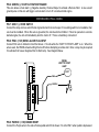
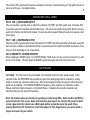
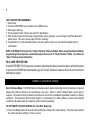
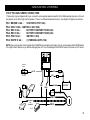
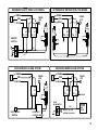
RS900ERII/RS901II
SERIES II
REMOTE ENGINE STARTING SYSTEM
INSTALLATION INSTRUCTIONS
This Remote Start Module provides the following features:
SELECTABLE ENGINE SPEED SENSING:
• Tach & “Smart Tachless” Modes
DYNAMIC CODE:
• Anti-Code Grabbing Protection
DEDICATED OUTPUTS FOR:
• OEM Factory Alarm Disarm
• OEM Factory Alarm Re-Arm
• Starter Disable / Anti-Grind Output
• Aux. Output (Trunk pop)
PROGRAMMABLE RUN TIME:
• 12, 24, 36, or 48 minutes
433Mhz TRANSMITTER FREQUENCY
• Better range / Less RF interference
VALET MODE / OVERRIDE
4 ON-BOARD RELAYS:
• Main Ignition (IGN1)
• IGN2 / Accessory
• Starter
• Parking Light
HOST ALARM ACTIVATION:
• Lets an Alarm AUX trigger
a remote start
REMOTE KEYLESS ENTRY:
• Controls power door locks
SECURITY STARTER DISABLE
CODE / TACH LEARNING CIRCUITRY
HOOD / BRAKE SAFETY CIRCUITRY
DIESEL START COMPATIBILITY
**Some of the features listed above are optional connections, and may require additional parts and labor.**
INSTALLATION CONSIDERATIONS / WARNINGS
TECHNICAL SUPPORT: 1-800-998-6880
Monday - Friday 8:00am - 4:30pm Pacific Time
Web Site: www.crimestopper.com
E-mail: [email protected]
CRIMESTOPPER SECURITY PRODUCTS, INC.
1770 S. TAPO STREET, SIMI VALLEY, CA. 93063
This device complies with FCC Rules part 15. Operation is subject
to the following two conditions: (1) This device may not cause
harmful interference, and (2) This device must accept any
interference that may be received, including interference that may
cause undesired operation. The manufacturer is not responsible
for any radio or TV interference caused by unauthorized
modifications to this equipment. Such modification could void the
user’s authority to use the equipment.
To ease and reduce installation time, we suggest you consider the following points before starting.
1. Determine most suitable locations for all components to be placed. These components include: the module
itself, override / programming switches, and possible relays.
2. Use a Volt-Ohm meter to test and locate all connections.
3. Record all color codes of vehicle wiring to be used for reference. This will save time by not having to re-test the
same wires over again.
4. Allow enough wire to create a service loop with strain relief, should servicing be required. This will also allow
easier access and mounting.
**FOR SAFETY REASONS, DO NOT INSTALL RS900/901 in vehicles with MANUAL TRANSMISSIONS.** If
accidentally left in gear, a remote started vehicle could become a self-propelled threat to life and property.
DO NOT extend the RS-900 Remote start ignition harness length. Mount the module so that main harness reaches
all ignition switch wiring. Extending these wires could result in poor performance.
DO NOT route any wiring that may become entangled with brake, and gas pedals, steering column, or any other
moving parts in the vehicle.
DO NOT exceed the rated output current of any circuit on the Remote start module. Failure to observe this warning
will result in damage to the unit.
DO NOT remote start the vehicle in a closed garage. Make sure that the garage door is open or there is adequate
ventilation. Failure to observe this rule could result in injury or death from poisonous Carbon Monoxide fumes.
Warning: This system DOES NOT HAVE engine over-rev protection. Make certain
vehicle throttle linkage operates properly and does not stick. A stuck throttle will
1
WIRING INSTRUCTIONS
PROGRAM/OVERRIDE SWITCH: 2 PIN PLUG
This switch is used primarily for programming features of the RS900/901. However, if the Anti-Grind/Starter disable
feature is installed, you MUST INSTALL this switch. This switch will allow the user to override the starter disable in
the event of a non-operating remote control.
LED: 2 PIN PLUG
The LED is only used as a VALET/PROGRAMMING indicator. The LED comes on solid when the unit is in valet or
programming mode. The LED is not a mandatory installation item.
12 PIN PLUG:
PIN 1: YELLOW: (-) IGNITION 1 OUTPUT (FOR RELAY)
PIN 2: YELLOW/WHITE: (-) IGN2/ACC OUTPUT (FOR RELAY)
Use these wires when the vehicle requires a second IGNITION 1, IGNITION 2, or ACCESSORY wire to be
activated. This occurs commonly in Toyota, and late model GM cars. See diagram below:
YELLOW
OR
(YELLOW/WHITE)
85
86
30
87
INSERT DIODE AS SHOWN
+
BATTERY
2nd IGN 1
OR
(2nd IGN2 /ACC WITH YEL/WHT)
PIN 3: BLACK: MAIN SYSTEM GROUND
Connect to chassis metal of the vehicle. An existing bolt or screw MAY provide an adequate ground, or drill a small
hole, scrape away paint and attach using a sheet metal screw & star washer. If this wire is not connected OR
connected to a point on the vehicle that provides a poor ground, undesirable and inconsistent operation will occur.
This is a mandatory connection.
2
WIRING INSTRUCTIONS
PIN 4: YELLOW/BLACK: (-) ANTI-GRIND/STARTER KILL OUTPUT
Use this wire for the negative side of the Anti-Grind/Starter Disable relay. It can also be used for the sensor disable
circuit for a host alarm for RS901. This output activates whenever a remote start is requested, and when the
vehicle is remotely locked with the transmitter. See diagram below.
TO
MOTOR
IGN 1
IGN 2
ACC
START
CUT
BROWN
YELLOW/BLACK
85
86
MAKE CERTAIN TO CONNECT "BROWN" START OUTPUT WIRE TO
MOTOR SIDE OF ANTI-GRIND/START DISABLE RELAY.
PIN 5: TAN: (-) AUX OUTPUT (TRUNK POP)
This output will provide a ground pulse when button #3 on the remote transmitter is pushed to activate a factory
electric trunk release or other optional accessory. Note: this is a momentary output that will stay on as long as
the remote button is pressed.
PIN 6: GREEN: (-) START ACTIVATION TRIGGER
This wire allows a host alarm (-) Negative Auxiliary Channel Output to activate a Remote Start. A one second
ground pulse on this wire will trigger a remote start or turn off a remote started engine.
WIRING INSTRUCTIONS
PIN 7: GRAY: (-) HOOD SWITCH
Connect the Gray wire to a switch that is at ground when the hood is open. If an existing switch is not available, then
one must be installed. When this wire is grounded, the remote start is inhibited. If hood is opened on a remote
started engine, the unit will immediately shut the motor off. This is a mandatory connection!
PIN 8: PINK: (+12V) DIESEL GLOW PLUG INPUT
Connect Pink wire to indicator circuit that shows +12 volts while the “WAIT TO START LAMP” is on. When this
wire is used, the RS900 will wait until light turns off before attempting a remote start. Note: a relay may be required
for vehicles that have a Negative Wait to Start lamp. See Diagram Below.
DIESEL
WAIT TO START
LAMP
WAIT
PINK
PURPLE
PIN 9: PURPLE: (+12V) BRAKE RESET
Connect the Purple wire to the side of brake pedal switch that shows +12 volts ONLY when pedal is depressed.
This will turn off the remote start if someone attempts to drive the car without the keys or if the Ignition key is not
turned on all the way. See diagram above.
4
WIRING INSTRUCTIONS
PIN 10: TAN: (-) OEM DISARM OUTPUT
This wire provides a ground pulse to disarm the vehicles' FACTORY anti-theft system prior to Remote Start.
Connect this wire to the vehicles' anti-theft disarm wire. This wire is may found coming off the Driver's door key
switch or the Factory Anti-theft control module. This wire may not be needed if Factory Security only requires a door
unlock pulse.
PIN 11: TAN: (-) OEM REARM OUTPUT
This wire provides a ground pulse to rearm the vehicles' FACTORY anti-theft system after remote start, along with
door lock pulse, and after an aborted Remote Start. Connect this wire to the vehicles' anti-theft rearm wire or to the
door pin circuit depending on your requirements.
PIN 12: RED/WHITE: TACHOMETER INPUT
When installing the RS900 Series II in CONVENTIONAL TACH mode, this wire must be connected to a valid
source of AC voltage. This wire allows the RS900 to sense the engine and control the starter motor.
TACH MODE
Tach Mode: The Tach mode is the most reliable and consistent method of engine speed sensing. When
using this mode, the WHITE/RED wire provides the input for the pulsing signal that is created by a running
engine to monitor and control the starter motor. Most modern engines include various points where this proper
signal may be obtained. TACH SENSE EXAMPLES: Negative (-) side of ignition coil, Distributor, Ignition
Module, Coil Pack, Engine Computer, or Crankshaft Sensor. Sometimes Fuel injection solenoids, and
Alternator stator pins can be used if necessary.
Note: The locations above are provided as a guide, your vehicle may differ. Some locations will NOT be
a good location for Tach source. Some of the locations given may be too noisy for the system to detect
a clean signal and/or the vehicle uses a Multi-spark ignition system that varies the spark. (Noisy
meaning Electrical or RF interference) Call Crimestopper for Tech Support when you cannot locate a
proper tach source for your vehicle.
5
TACH SOURCE PROGRAMMING:
1. Open hood
2. Connect WHITE/RED wire to Ignition coil or RPM source.
3. Start engine with key.
4. Press program button 5 times, then wait for 5 light flashes.
5. Wait at least one second then push program button slowly (4) times, you should get a light flash after each
button press. This unit is now at option #4-Tach Learning.
6. Press Button #1 on the transmitter and the unit will read the Tach source and flash the lights twice for
confirmation.
NOTE: THE RS900 II is Factory Set in “Smart Tachless” Mode by default. When using Standard Tach Mode,
programming the tach pulses automatically takes the unit out of “Smart Tachless” Mode. See below for
“Smart Tachless mode information.
FAIL SAFE PROTECTION:
If the WHITE/RED TACH input wire becomes disconnected due to wear and tear or when the vehicle
is serviced, the RS900 will automatically go into “Smart Tachless” mode to allow the unit to continue
starting the engine
“SMART TACHLESS” MODE
Smart Tachless Mode- This RS900 Series II includes custom vehicle monitoring circuitry that allows it to start an
engine with optimum efficiency and consistency every time. When in Smart Tachless Mode no tach wire is
required. The system actively monitors the vehicle over the life of the installation regardless of weather or battery
conditions. This allows the Remote Start System to compensate for a fading battery or harsh environmental
conditions and adjusts itself as needed for optimum starting capability.
TO SET SMART TACHLESS MODE: (No Tach Wire Required)
1) Turn on headlights about 20 seconds to drain off surface charge of the vehicle battery. This step is not needed if
the vehicle has been sitting for 2 hours or more.
2) Connect the +12V input wires to the RS900 Series II.
3) The unit will automatically read and program itself for your vehicle when 12 volts is applied.
6
SMART TACH JUMPERS: (Remove Access Door on top of module)
The purpose of the jumpers is to reduce the cranking time of starter crank when in “Smart Tachless” mode only.
PIN ORIENTATION: Looking at remote start upright with harnesses facing down (or towards you).
To shorten the crank time adjustment one level, remove the jumper at the far right. Test the unit and see if the
decrease is correct. If a shorter crank time is still required, then remove the middle jumper. Test the unit and see if
the decrease is correct. There are only (2) adjustments. Removing the third jumper will not make any change to
the crank time. These (2) setting should correct most cranking times when in Smart Tachless mode.
NOTE: (1) If you connected the 12 volts lines early in the install before connecting the input and output
wires, the RS900 may not have the correct reference for your vehicle. If this is the case, power down the
unit and perform the steps under “Smart Tachless” mode again.
(2) If you have changed battery in the vehicle, wait 2 hours before attempting a remote start or wait
for 2 hours after the vehicle has been driven to allow the unit to update itself to the new battery.
TACH WIRE TROUBLESHOOTING-TACH MODE
TACH wire trouble shooting applies to installations using Tach learning mode, not “Smart Tachless”. If all remote
start wiring has been completed, attempt a remote start. If engine starts, and starter disengages quickly, and
engine continues to run, the tach wire has been properly connected.
** If system does not remote start properly, you will have to locate a different tach wire and reprogram.
AN INADEQUATE TACH SOURCE WILL PRESENT ANY VARIETY OF THE FOLLOWING PROBLEMS:
• Starter stays engaged after engine starts.
• Starter releases properly when engine starts, but engine then stalls BEFORE the time out. System may re-start.
• Starter releases properly, and engine runs, but then starter re-engages. (This makes a terrible grinding noise
and the system must be shut off as quickly as possible to prevent damage to starter and flywheel).
7
IGNITION SWITCH WIRING
5 OR 6* PIN HIGH-CURRENT CONNECTORS:
( *Some units may be shipped with a 5-pin connector and a separate spade connector for the White parking lamp wire or the unit
may have 6 pin for all the High-Current spades. There is no difference between the two.) See diagram for typical connections.
PIN 1: BROWN 14 GA. :
STARTER OUTPUT (30A)
PIN 2: GRAY 14 GA. : IGNITION 2 / ACC (30A)
PIN 3: RED 14 GA. :
BATTERY CONSTANT FUSED (30A)
PIN 4: RED 14 GA. :
BATTERY CONSTANT FUSED (30A)
PIN 5: PINK 14 GA. :
IGNITION 1 (30A)
PIN 6: WHITE 18 GA. :
(+) PARKING LIGHTS (10A)
NOTE: Heavy duty Ignition circuits (greater than 30 AMPS) require high-current relays. Do not use the outputs of the RS900 Series
II for High-Current systems or you will risk damaging the unit. Use Crimestopper Part #CS-403 relays for circuits up to 70 amps.
PARKING
LIGHTS
RED
WHITE
FUSE
30A
RED
+10A MAX.
FUSE
30A
+
FUEL
PUMP
+
ENGINE
ECU
PINK
BROWN
GRAY
-
BATTERY
STARTER
-
COIL
IGN 1
TRANSMISSION
ECU
2nd IGN 1
OR
2nd IGN 2
IGN 2
H/V/AC
8
POWER DOOR LOCK WIRING
3 PIN DOOR LOCK PLUG:
PIN 1: GREEN: (-) Negative pulse for LOCK
PIN 2: RED: +12V Coil Power for external relays TERM 86.
PIN 3: BLUE: (-) Negative pulse for UNLOCK
DETERMINING DOOR LOCK TYPE: We recommend determining the type of locking system the vehicle has
before connecting any wires. Incorrect connection will result in damage to the remote start and/or vehicle
locking system. There are several types of door lock systems in vehicles today. Below is listed the many types
of common locking systems:
Negative trigger: Most Japanese; Ford, New GM
Positive trigger: Many GM; Some Chrysler
One wire dual voltage: Newer /Chrys/Dodg/Plym; Ford Probe
Reverse Polarity: Chrys/Dodg/Plym; GM; Ford
Ground/open: Some Nissan; Subaru
Semi-automatic: Older Saab and Volvo
Electric vacuum pump: Pre-‘95 Mercedes-Benz
DOOR LOCK DIAGRAMS
NEGATIVE TRIGGER DOORLOCK WIRING
POSITIVE TRIGGER DOORLOCK WIRING
GREEN
GREEN
RED
RED
BLUE
BLUE
FUSED
+12V
+
85
86
87
87A 30
L
UL
FACTORY
POWER
LOCKING
RELAYS
L
UL
85
86
87
87A 30
FACTORY
POWER
LOCKING
RELAYS
REVERSE POLARITY DOOR LOCK WIRING
AFTERMARKET MOTOR/DOOR LOCK WIRING
GREEN
GREEN
FUSED
+12V
+
RED
BLUE
85
86
87
87A 30
85
FUSED
+12V
+
RED
BLUE
85
86
86
87
87A 30
87
87A 30
85
86
87
87A 30
MASTER
SWITCH
+
L
CUT
UL
CUT
GROUND/OPEN LOCKING SYSTEM
GREEN
FUSED
+12V
+
RED
BLUE
85
MERCEDES-BENZ VACUUM SYSTEM
GREEN
FUSED
+12V
+
RED
BLUE
86
85
87
87A 30
86
85
87
87A 30
87
87A 30
DOOR
MICROSWITCH
CUT
DOOR MICRO
SWITCH
DOOR LOCK
CONTROL MODULE
86
BLUE or YELLOW
WIRE IN KICK PANEL
GROUND
CENTRAL
LOCKING
PUMP
MOTOR
10
TRANSMITTER PROGRAMMING
Transmitter Code Learning: (Excludes RS901)
Note: All transmitter codes must be learned at time of programming!! The RS900 allows storage of up to 4
different transmitter codes.
1. Open Hood. (Ground Gray wire.)
2. Turn key to the ON position. (Doors will lock if Autolock is programmed)
3. Press Programming button 4 times, then after a few seconds the unit will flash the parking lights 4 times.
4. Press button #1 of the transmitter to be coded. You should get light flashes with each code learned. If all 4 code
locations are learned, the unit will automatically exit code learning mode, otherwise turn key off and close hood.
OPTION PROGRAMMING
This system has several installer programmable features. See chart below for features.
Options Programming:
1. Open hood
2. Turn Key to the ON position
3. Press program button 5 times, after a few seconds the unit will flash the lights 5 times.
4. Slowly push the program button the number of times that corresponds to the option number desired. You
should get a light flash after each button press.
5. When you reach the desired programming level, Press button #1(LOCK) on the transmitter to change the
option from the factory default or Press button #2 (UNLOCK) to return the option back to default (except for
the Run Time option.) See chart below.
PROGRAMMING OPTIONS CHART
Option #
Option Description
Option Values
1
2
3
4
Autolock with Ignition
Door Lock Pulse Time
Double Unlock Pulse
Tach Learning
On or Off.
.075 or 3.0 sec.
On or Off
N/A
5
Remote Start Run Time
6
Option reset
Button #1 = 12 min.
Button #2 = 24 min.
Button #3 = 36 min.
Button #4 = 48 min.
Button #2
Fac. Pre-set
ON
.075
OFF
N/A
24 min
N/A