1
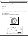
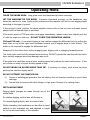
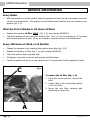
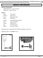
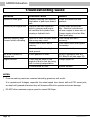
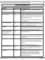
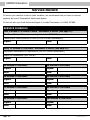
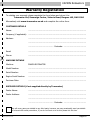
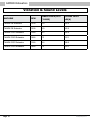
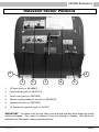
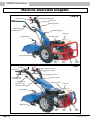
Rotavators
Models
C6 · C8 · C10 · C13
with PowerSafe® Clutch
Operating Instructions
Before commissioning the machine, read operating instructions
and observe warning and safety instructions.
CAMON Rotavators
Contents
Page 3
Safety
Page 4
Controls Diagrams - C6/C8 & C10
Page 5
Controls Diagrams - C13
Controls Description
Page 6
Assembly Instructions
Page 7
How to Start Petrol Engine
How to Start Diesel Engine
Operation
Page 8
How to Stop Engine
Page 9
Operating Hints
Page 10
Replacing the Tines
Page 11
Adjusting the Rotavator Width
Page 12
Maintenance Guide
Page 13
Maintenance Programme
Page 14
Service Information
Page 16
Troubleshooting Guide
Page 17
Risk Assessment
Page 18
Service Record
Page 19
Warranty Registration
Page 20
Vibration & Sound Levels
Page 21
Rotavator Sticker Positions
Page 22
Machine Overview Diagrams
!
IMPORTANT
READ CAREFULLY
No liability will be accepted for any damage caused to persons or property
through failure to observe the operating and safety instructions.
Page 2
PSR/AM/0914
CAMON Rotavators
Safety
ALWAYS start the engine in the open air
DO NOT smoke when refuelling
DO NOT mix OIL with the fuel
ALWAYS stop the engine before making any adjustments, refuelling, moving or
cleaning, or when the unit is unattended
USE ONLY fuel from containers designed for this purpose - refuel outdoors only and
replace the tank cap securely
IN CASE of petrol spillage move the machine away from the area of spillage and allow
the petrol vapours to dissipate before starting the engine
DO NOT remove any safety guards that are fitted
DO NOT touch any moving parts or attempt any maintenance whilst the machine is
running - KEEP HANDS AND FEET AWAY
BEFORE starting work clear the work area of any objects that could damage the
machine
DO NOT allow children or anyone uninstructed to operate the machine - KEEP
ANIMALS AWAY
DO NOT use on slopes or banks of more than 20o
ALWAYS wear suitable clothing to give personal protection including footwear that
offers a good grip
AVOID wearing loose garments that may catch in moving parts
KNOW how to stop the machine in an emergency
NEVER interfere with any control settings on the engine
NEVER select reverse gear with your back to a wall or other immovable object
IF A FAULT develops DO NOT attempt any repair - immediately contact the supplier
from whom the machine was obtained
VISUALLY INSPECT the machine before use - ensure all tines, nuts and bolts are tight
and not worn or damaged and replace tines if necessary
KEEP IN MIND the operator is responsible for accidents or hazards occurring to people
or property
PSR/AM/0914
Page 3
CAMON Rotavators
Controls
A
B
N
F
C
E
D
G/H
C6 / C8
L
B
G
N
D
E
M
A
F
C
C10
Page 4
H
PSR/AM/0914
CAMON Rotavators
Controls
B
L
G
N
A
E
D
O
F
C
P
M
C13
H
Controls Description
(A)
OPC LEVER (red lever that stops the machine when released)
(B)
ENGINE STOP LEVER
(C)
CLUTCH CONTROL LEVER
(D)
GEAR LEVER (the location of different gears are shown on the selector)
(E)
PTO LEVER (there is a safety device that prevents engagement with reverse gear)
(F)
THROTTLE LEVER
(G)
HANDLEBAR HEIGHT ADJUSTMENT LEVER
(H)
STEERING COLUMN SWIVEL LEVER
(L)
FORWARD/REVERSE LEVER (always engage the clutch before engaging this lever)
(M)
DIFFERENTIAL LOCK LEVER
(N)
PARKING BRAKE LEVER
(O)
RIGHT BRAKE LEVER
(P)
LEFT BRAKE LEVER
PSR/AM/0914
Page 5
CAMON Rotavators
Assembly Instructions
1. Remove the machine from its packing case.
2. Rotate the handlebar stem to the operating position and fit the handlebars - check operation and
routing of cables.
3. Fit the wheels, ensuring the correct rotation (see diagram A below) and check the tyre pressures
(20psi).
4. Fit the gearbox dipstick.
5. Assemble the rear flap on the digging unit ensuring the sticker labels are on the outside (see
diagram B below) and attach the unit to the machine.
6. Check the engine oil level.
7. Follow the instructions in this Owner’s Manual to run the machine.
Diagram A
Diagram B
Page 6
PSR/AM/0914
CAMON Rotavators
To Start Petrol Engine
Using the dipstick provided, check the engine oil level. Top up with 10w/40 oil if necessary.
Check fuel level. Only use unleaded petrol from a clean container. Never re-fuel when the engine is
hot or running. Leave 1” air space in the fuel tank.
Turn the fuel tap to ‘ON’ position, if the engine is cold set the choke lever to ‘ON’ position.
Before starting the engine ensure the gear lever (D) is in neutral position and the power take-off
(PTO) lever is disengaged (E).
Apply half throttle (F).
Move the engine stop lever (B) to position 1 ‘ON’.
Pull the recoil start handle gently until it engages then give it a good strong pull to start the engine.
When the engine has started, release the choke lever after a few seconds and return the throttle
lever (F) to idle position.
To Start Diesel Engines
Lombardini Diesel Engines
Yanmar Diesel Engines
Using the dipstick provided, check the engine oil
level. Top up with 10w/40 oil if necessary.
Using the dipstick provided, check the engine oil
level. Top up with 10w/40 oil if necessary.
Check fuel level. Only use diesel from a clean
container. Never re-fuel when the engine is hot
or running.
Check fuel level. Only use diesel from a clean
container. Never re-fuel when the engine is hot
or running.
Before starting the engine ensure the gear lever
(D) is in neutral position and the power take-off
(PTO) lever is disengaged (E).
Before starting the engine ensure the gear lever
(D) is in neutral position and the power take-off
(PTO) lever is disengaged (E).
Apply ¾ throttle (F).
Apply ¾ throttle (F).
Move the engine stop lever (B) to position 1 ‘ON’.
Move the engine stop lever (B) to position 1 ‘ON’.
Pull the recoil start handle gently until it
engages then give it a good strong pull to start
the engine.
Press and hold the decompression lever on top
of the engine.
Once the engine has started return the throttle
lever (F) to idle position.
Pull recoil start handle gently until it engages
then, keeping the decompression lever
depressed, slowly pull the engine over 2-3 times
to prime the engine.
Release the decompression lever and gently pull
over the engine until compression is felt.
Press, but do not hold, the decompression lever
and give the starter handle a good strong pull to
start the engine.
Once the engine has started return the throttle
lever (F) to idle position.
PSR/AM/0914
Page 7
CAMON Rotavators
Operation
Use handlebar adjuster (G) to set handlebar height.
Hold the handlebar and pull up the clutch lever (C).
Depress the red OPC lever (A) and select working speed 1 (D). NEVER select a higher wheel speed
for work.
Ensure forward/reverse lever is in forward position (L).
Engage drive to the digging knives by pushing the PTO lever (E) forward.
Release clutch lever (C) slowly and fully, keeping the red machine stop lever depressed as the
machine will stop if released.
Commence work.
To Stop Engine
Close the throttle (F).
Engage clutch lever (C).
Locate gear lever (D) in neutral position.
Disengage drive to the digging knives by pulling the PTO lever (E) backwards.
Release clutch lever (C).
Release the red OPC lever (A) completely.
Move the engine stop lever (B) to position O ‘STOP’.
WARNING: THE EXHAUST COVER MAY BE HOT - DO NOT TOUCH.
Page 8
PSR/AM/0914
CAMON Rotavators
Operating Hints
CLEAR THE WORK AREA. Long grass must be cleared and all debris removed.
LET THE MACHINE DO THE WORK. Excessive downward pressure on the handlebars may
cause the machine to jump. Apply gentle pressure and the machine will find its own digging depth
according to the type of ground.
If the ground is hard, position the depth adjuster centre knife on the top hole and make several
passes until the desired depth is achieved.
If the wheel speed or PTO lever does not engage immediately, release clutch lever slightly and ‘feel
in’ with the engine on tick-over. DO NOT FORCE THE OPERATING LEVERS.
C10 and C13 only - if one wheel begins to lose traction engage the differential lock by pulling the
black lever on top of the right hand handlebar towards you to engage drive to both wheels. The
clutch is not required to engage the differential lock.
Always pull in the clutch lever before engaging gear, digging unit or changing forward/reverse.
The clutch lever must be fully released when working. DO NOT operate the machine with the clutch
lever partially engaged as serious damage may occur.
If the ground is hard then using a lower working speed will produce the best performance. If the
soil is loose or sandy a higher working speed is best.
DO NOT WORK ON SLOPES MORE THAN 20°. If working on a slope, work across the slope
pointing the machine slightly uphill.
DO NOT ATTEMPT CULTIVATION ON:
(i) Frozen or waterlogged ground as this will destroy the soil structure resulting in poor future
drainage.
(ii) Ground that is covered with thick foliage or high grass. Remove it by cutting down.
DEPTH ADJUSTMENT
Digging depth changes are made through use of the
central knife.
For shallow digging, set the lever all the way in.
To increase digging depth, raise the control lever.
Whilst rotavating, the handlebars can be offset to avoid
walking on the cultivated soil, and adjusted in height
for the comfort and safety of the operator.
PSR/AM/0914
Page 9
CAMON Rotavators
Replacing the Tines
To replace the tines, it is
necessary to remove the
rotavator attachment from
the power unit.
Once removed, turn the
rotavator upside down to
facilitate replacement of
the tines.
LOOK CAREFULLY AT THE
ORIENTATION OF THE
TINES.
Replace the tines one at a
time so that you can use
the remaining tines as a
reference.
IMPORTANT: When replacing the tines, enure that they are
mounted with the cutting edge in the same position as shown
in the picture above.
Page 10
PSR/AM/0914
CAMON Rotavators
Adjusting Rotavator Width
The rotavator width can be adjusted using the following configurations:
Current unit
No of
Tines
No of
Flanges
Increase or
Decrease
New
No of
configuration Tines
No of
Flanges
52cm (20”)
16
4
Increase
66cm (26”)
20
6
66cm (26”)
20
6
Decrease
52cm (20”)
16
4
80cm (32”)
24
6
Decrease
66cm (26”)
20
6
PLEASE NOTE: The 46cm rotavator attachment (12 tines on 4 flanges) cannot be adjusted in size
52cm (20”) - 16 tines on 4 flanges
66cm (26”) - 20 tines on 6 flanges
80cm (32”) - 24 tines on 6 flanges
PSR/AM/0914
Page 11
CAMON Rotavators
Maintenance Guide
For engine maintenance please refer to engine manufacturers manual.
After every hour of operation stop the engine and remove the spark plug cap. Check engine oil level
(recommended oil SAE 10w/40). Before checking the oil level ensure the machine is level.
Remove all foreign matter from the digging knives assembly e.g. wire, string, grass etc.
After every 100 hours of use, or once a year (whichever is sooner), check that the oil level in the
rotavator transmission is within 50mm (2”) of the hole.
To perform this operation, remove the bolts that attach the
support rod to the rotavator transmission and the depth
handle to the central knife. Raise the rotavator hood, remove
the plug and check the oil level, making sure the machine
is level. If necessary top up with SAE 80w/90 EP gear oil.
Reassemble the unit by performing the operations in reverse.
Remove the gearbox unit dipstick and ensure the oil reaches the top level mark, if necessary top up
with API GL-5 80w/90 gear oil (see pages 14-15 for more details).
Replace the spark plug cap.
Do not turn the machine on its side for cleaning.
Page 12
PSR/AM/0914
CAMON Rotavators
Maintenance Programme
OPERATION
ENGINE
Check engine oil level 10w/40
See separate engine manual
GEARBOX Check gearbox oil level
(see page 15)
&
CONTROLS Check nuts & bolts
EVERY
DAY
EVERY
WEEK
X
X
X
X
X
X
Ensure clutch cable has free play
X
Check tyre pressure (20psi)
X
Lubricate control cable/linkages
X
Check control cable operation
X
Check operation of safety devices
X
EVERY YEAR
or 100 HOURS
X
Change gearbox oil (see page 15)
DIGGING
UNIT
Grease gear speed detent ball
X
Check condition of centre knife
X
Tighten nuts & bolts on knives
X
X
Check nuts & studs on side flange
X
X
Check drive unit oil level EP90
X
X
X
NOTES:
* Pressure washing machines removes lubricating grease as well as dirt.
It is imperative all linkages, especially the wheel speed lever detent ball and PTO swivel joint,
are kept well greased otherwise they will become difficult to operate and cause damage.
* DO NOT allow maximum engine speed to exceed 3600rpm.
PSR/AM/0914
Page 13
CAMON Rotavators
Service Information
Every Week
•
With the machine on a level surface, check the gearbox oil level, top up as necessary using the
correct oil as listed below. The gearbox oil level should reach between the two notches on the
dipstick (fig. 2, C).
After the First 2 Weeks or 30 Hours of Work
•
Replace the gearbox oil filter ONLY, (fig. 1, A), part number 58056249.
•
Check the gearbox oil level using the dipstick (figs. 1 & 2, C), run the machine for 2-3 minutes
and recheck gearbox oil level, top up as necessary using the correct oil as listed below.
Every 100 Hours of Work or 12 Months
•
Change the gearbox oil by removing the gearbox drain plug (fig. 3, B).
•
Replace the gearbox oil filter (fig. 1, A), part number 58056249.
•
Clean the gearbox drain plug and refit.
•
Fill gearbox using the correct oil and quantity as listed below.
•
Check the gearbox oil level, run the machine for 2-3 minutes and recheck gearbox oil level.
C
Fig. 1
To replace the oil filter (fig. 1, A)
1. Using the correct spanner, remove the
filter.
2. Smear a film of oil on the rubber gasket
of the new filter.
3. Mount the new filter, screwing and
tightening by hand only.
A
Page 14
PSR/AM/0914
CAMON Rotavators
Service Information
Gearbox Oil Quantities
CAMON C6/C8/C10 = approx 2.3 litres
CAMON C13 = approx 2.6 litres
Oil Type
Fuchs
Titan Hyp 90
Valvoline
80w-90 GL-5
Morris
EP80w/90 API GL5
Castrol
EPX 80w-90
Motorex
Hypoid SAE 80w/90 API GL5
Millers
Hypoid 80w90 GL5
Comma
EP80w-90 GL5
Agip
Rotra MP 80w-90
Rock Oil
SD API GL5 80w/90
Alternatively any oil meeting API GL-5 80w/90 specification may be used.
Multigrade engine oil must NOT be used.
Fig. 2
C
PSR/AM/0914
B
Fig. 3
Page 15
CAMON Rotavators
Troubleshooting Guide
PROBLEM
POSSIBLE CAUSE
REMEDY
Unable to select gear
Pressure washing has removed
lubrication of gear lever detent
ball.
Grease the detent ball and
quadrant.
Unable to pull engine over
Machine has been tipped on
side for cleaning and engine
oil has filled the cylinder bore
causing a hydraulic lock.
Remove spark plug and air
filter. Stand to one side and
pull over engine to clean out oil.
Change engine oil and air filter.
Clean spark plug.
Machine suddenly leaps
forward whilst cultivating
New set of tines has been fitted
the wrong way round.
Check fitting and refit if
necessary.
Centre knife is worn out or
missing.
Check centre knife and replace
if necessary.
Centre knife lifted too high on
hard ground.
Lower centre knife.
No drive to wheels or
digging unit
Check gearbox oil level.
Top up if necessary with API
GL-5 80w/90 oil (see page 15).
Engine smokes
There may be petrol in the
engine oil due to fuel tap being
left on during transportation.
Change engine oil.
Contaminated air filter.
Replace element.
NOTES:
* Pressure washing machines removes lubricating grease as well as dirt.
It is imperative all linkages, especially the wheel speed lever detent ball and PTO swivel joint,
are kept well greased otherwise they will become difficult to operate and cause damage.
* DO NOT allow maximum engine speed to exceed 3600rpm.
Page 16
PSR/AM/0914
CAMON Rotavators
Risk Assessment
HAZARDS
RISK LEVEL
General
ACTION NEEDED
The machine should only be used by trained
operators.
Machine tipping over
Low
Do not use on slopes over 25o.
Machine jumping
High
Ensure the centre knife is in good condition and
adjusted to suit the ground conditions. Use the
depth adjuster located on top of the rotavator to
adjust the centre knife.
NEVER apply excessive downwards pressure on
the handlebars.
Machine running away
Low
Red OPC lever disengages the drive to the
implement if the operator releases the handlebars.
Always check operation before use.
Lacerations
Medium
Remove the spark plug cap before carrying out
any maintenance or cleaning. Always wear gloves
when cleaning the tines or removing debris.
Machine reversing and
jamming operator against
immovable object
High
Never reverse the machine with your back to a
wall or similar object.
Burns
High
Be very careful or a hot exhaust. Turn off the
machine before refuelling. Allow 1” air space in
the fuel tank.
Flying objects
Low
Ensure the back flap moves easily and follows the
contour of the ground to prevent small stones
being thrown back. Always wear suitable safety
footwear.
NEVER use the back flap as a grader.
Handlebar adjustment
Low
Always set the height and sideways position
before operating the machine - never while it is
moving.
Foot injuries
Medium
The machine has a safety device to prevent the
reverse speed and tine drive being engaged
simultaneously. Ensure all safety devices are in
place before using the machine. Always wear
suitable safety footwear.
PSR/AM/0914
Page 17
CAMON Rotavators
Service Record
To ensure your machine is kept in peak condition, we recommend that you have it serviced
regularly by one of Tracmaster’s Authorised Agents.
To find out who your local Authorised Agent is, contact Tracmaster on 01444 247689.
SERVICE SCHEDULE
First 2 Weeks or 30 Hours of Work - whichever is sooner (see page 15)
First PowerSafe® oil filter replacement (part number 58056249)
Check and/or restore gearbox oil level (API GL-5 80w90 specification)
Signed:
Date:
Every 12 Months or 100 Hours - whichever is sooner (see page 15)
Implement transmission oil replacement (API GL-5 80w90 specification)
Engine oil replacement (SAE 15w/40)
Signed:
Date:
24 Months or 200 Hours
36 Months or 300 Hours
Signed:
Signed:
Date:
Date:
48 Months or 400 Hours
60 Months or 500 Hours
Signed:
Signed:
Date:
Date:
72 Months or 600 Hours
84 Months or 700 Hours
Signed:
Signed:
Date:
Date:
96 Months or 800 Hours
108 Months or 900 Hours
Signed:
Signed:
Date:
Date:
Page 18
PSR/AM/0914
CAMON Rotavators
Warranty Registration
To validate your warranty please complete the form below and return it to:
Tracmaster Ltd, Sovereign Centre, Victoria Road, Burgess Hill, RH15 9LR
Alternatively visit www.tracmaster.co.uk and complete the online form.
CUSTOMER DETAILS
Name: ....................................................................................................
"
Company (if applicable): ....................................................................................................
Address: ....................................................................................................
....................................................................................................
............................................Postcode: .......................................
Email: ....................................................................................................
Phone: ....................................................................................................
MACHINE DETAILS
Machine:
CAMON ROTAVATOR
Model Number: ....................................................................................................
Serial Number: ....................................................................................................
Engine Serial Number: ....................................................................................................
Purchase Date: ....................................................................................................
SUPPLIER DETAILS (if not supplied directly by Tracmaster)
Dealer Name: ....................................................................................................
Dealer Address: ....................................................................................................
....................................................................................................
............................................Postcode: .......................................
We will never pass your details to any third party, however, we may occasionally send you details
of relevant offers and promotions, if you do not want us to do this please tick this box.
PSR/AM/0914
Page 19
CAMON Rotavators
Vibration & Sound Levels
MACHINE
RPM
VIBRATION M/SEC2
(3 AXIS)
SOUND LEVEL
dB(A)
CAMON C6 Rotavator
3100
2.9
85.0
CAMON C8 Rotavator
3100
2.9
85.0
CAMON C10P Rotavator
3000
4.3
85.0
CAMON C10D Rotavator
3600
7.3
97.0
CAMON C13P Rotavator
3000
4.4
88.0
CAMON C13D Rotavator
3600
7.3
97.0
Page 20
PSR/AM/0914
CAMON Rotavators
Rotavator Sticker Positions
4
4
3
5
1
1.
CE label (part no: 58046963)
2.
Read manual (part no: 58057724)
3.
How to use (part no: 580C0039)
4.
Beware rotating blades (2 off part no: 58046922)
5.
Adjustment (part no: 580C0054)
6.
To operate the machine (part no: 810937)
6
2
IMPORTANT: The labels must be kept clean from dust and mud and must always be clearly
visible and legible. They must be replaced if they are missing or illegible. New labels are
available from Tracmaster’s spare parts department.
PSR/AM/0914
Page 21
CAMON Rotavators
Machine Overview Diagram
OPC lever
Engine stop lever
C6 & C8
Parking brake lever
Throttle lever
Clutch lever
Wheel speed lever
Digging knives
engagement lever
Handlebar adjuster
Petrol cap
Gearbox oil level
Depth adjuster
Digging knives
Engine oil
level
Forward/reverse
lever
Differential lever
Throttle lever
Choke
lever
Fuel
tap
OPC lever
Recoil
starter
C10P
Parking brake lever
Engine stop lever
Clutch lever
Steering column
unlocking lever
Digging knives
engagement lever
Wheel speed lever
Gearbox oil level
Petrol cap
Handlebar adjuster
Depth adjuster
Digging knives
Engine oil
level
Page 22
Choke
lever
Fuel
tap
Recoil
starter
PSR/AM/0914
CAMON Rotavators
Machine Overview Diagram
Forward/reverse
lever
Differential lever
OPC lever
C13P & D
Parking brake lever
Throttle lever
Engine stop lever
Steering
column
unlocking
lever
Right brake
lever
Clutch
lever
Left brake lever
Wheel speed lever
Gearbox oil level
Petrol cap
Digging knives
engagement lever
Handlebar adjuster
Depth adjuster
Digging knives
Engine oil
level
Choke
lever
Fuel
tap
Recoil
starter
Decompression lever
YANMAR
DIESEL
ENGINE
PSR/AM/0914
Page 23
© Tracmaster Ltd 2014.
Specifications are subject to change without prior notice.
PSR/AM/0914
Tracmaster Ltd, Sovereign Centre, Victoria Road, Burgess Hill RH15 9LR
T: +44 (0) 1444 247689
F: +44 (0) 1444 871612
W: www.tracmaster.co.uk
E: [email protected]