1
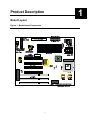
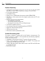
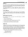
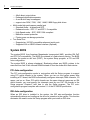
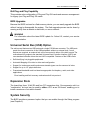
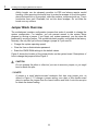
Yukon HX Motherboard User Manual Ver 2.0 Manufactured in Canada by Seanix Technology Inc. Seanix Technology Inc. makes no warranty of any kind with regard to this material, including, but not limited to, the implied warranties of merchantability and fitness for a particular purpose. Seanix assumes no responsibility for any errors that may appear in this document. Seanix makes no commitment to update nor to keep current the information contained in this document. No part of this document may be copied or reproduced in any form or by any means without prior written consent of Seanix. † Pentium is a registered trademark of Intel Corporation. AMI is a registered trademark of American Megatrends Inc. † Third-party brands and trademarks are the property of their respective owners. Copyright 1997, Seanix Technology Inc. Table of Contents PRODUCT DESCRIPTION ................................................................................................................................ 1 BOARD LAYOUT.................................................................................................................................................. 1 FEATURE SUMMARY............................................................................................................................................ 2 CENTRAL PROCESSING UNIT ................................................................................................................................ 2 MEMORY ............................................................................................................................................................ 3 CACHE MEMORY ................................................................................................................................................ 3 IDE PERIPHERAL INTERFACE............................................................................................................................... 3 SUPER I/O .......................................................................................................................................................... 3 SYSTEM BIOS .................................................................................................................................................... 4 UNIVERSAL SERIAL BUS (USB) OPTION. .............................................................................................................. 5 EXPANSION SLOTS .............................................................................................................................................. 5 SYSTEM SECURITY .............................................................................................................................................. 5 KEYBOARD/MOUSE CONTROLLER ....................................................................................................................... 6 REAL-TIME CLOCK AND CMOS RAM ................................................................................................................. 6 FAN CONNECTOR ................................................................................................................................................ 6 SPEAKER ............................................................................................................................................................ 6 USING THE BIOS SETUP PROGRAM............................................................................................................. 7 RECORD THE SETUP CONFIGURATION .................................................................................................................. 7 AMI BIOS SETUP MENU OVERVIEW ................................................................................................................... 7 OVERVIEW OF THE SETUP KEYS ........................................................................................................................... 9 STANDARD CMOS SETUP ................................................................................................................................. 11 ADVANCED CMOS SETUP................................................................................................................................. 12 ADVANCED CHIPSET SETUP ............................................................................................................................... 14 POWER MANAGEMENT SETUP ............................................................................................................................ 15 PCI/PLUG AND PLAY SETUP .............................................................................................................................. 16 PERIPHERAL SETUP ........................................................................................................................................... 18 AUTO-DETECT HARD DISKS .............................................................................................................................. 19 CHANGE USER PASSWORD & CHANGE SUPERVISOR PASSWORD .......................................................................... 19 AUTO CONFIGURATION WITH OPTIMAL SETTINGS .............................................................................................. 19 AUTO CONFIGURATION WITH FAIL SAFE SETTINGS ............................................................................................. 19 SAVE SETTINGS AND EXIT ................................................................................................................................. 20 EXIT WITHOUT SAVING..................................................................................................................................... 20 INSTALLING AND CONFIGURING JUMPERS & OPTIONAL COMPONENTS...................................... 21 BEFORE YOU BEGIN .......................................................................................................................................... 21 JUMPER BLOCK OVERVIEW ................................................................................................................................ 22 CPU / BUS SPEED / CLOCK RATIO JUMPERS ....................................................................................................... 24 HOW TO CLEAR CMOS CONTENTS: J8 ............................................................................................................. 25 BIOS MODE SELECT JUMPERS: J11 .................................................................................................................. 26 CASE CONNECTOR BLOCK: J36 ........................................................................................................................ 27 MAIN POWER CONNECTORS: J12, J13............................................................................................................... 28 ON-BOARD SCSI BIOS AND DRIVERS (MANUFACTURING OPTION)..................................................................... 28 UPGRADING P54C TO P55C .............................................................................................................................. 35 INSTALLING THE OPTIONAL USB/PS2 ADD-ON CARD .......................................................................................... 37 INSTALLING SIMMS ......................................................................................................................................... 38 REMOVING SIMMS ........................................................................................................................................... 40 ERROR AND INFORMATION MESSAGES .................................................................................................. 41 BEEP CODES ..................................................................................................................................................... 41 ERROR MESSAGES ............................................................................................................................................ 42 BIOS UPDATE .................................................................................................................................................. 45 BIOS UPDATE .................................................................................................................................................. 45 TABLES 1. ............................................................................. Supported SIMM Sizes ................................................................................................................ 34 2. ......................................................... Memory Options for SIMM Sockets ................................................................................................................ 34 FIGURES 1. .........................................................................Motherboard Components .................................................................................................................. 1 2. ............................................................................ Jumper Block Locations ................................................................................................................ 20 3. .....................................................................Standard Internal SCSI cable ................................................................................................................ 29 4. .................................................................. External SCSI cable (optional) ................................................................................................................ 30 5. ............................................................................................. P55 Upgrade ................................................................................................................ 31 6. .......................................................................... Installing a 72-Pin SIMM ................................................................................................................ 35 1 Product Description Board Layout Figure 1. Motherboard Components 1 1 Product Description Feature Summary • Intel Pentium® microprocessor running at 75, 90, 100, 120, 133, 150, 166, and 200 MHz OR Intel Pentium® MMX microprocessor running at 166 and 200 MHz. • AT form factor motherboard • Intel 82430HX PCIset • Support for up to 128 MB single in-line memory modules (SIMMs) DRAM • AMI BIOS in a flash memory device that supports system setup and PCI autoconfiguration • Expansion slots for up to six add-in boards Three dedicated PCI-bus slots Two dedicated dedicated ISA-bus slots One "shared" slot for either a PCI or an ISA add-in board • Two RS-232-compatible serial ports • One multimode, Centronics†-compatible parallel port (ECP/EPP) • Adaptec AIC-7860 Ultra-SCSI (optional) • USB (optional add-on card) • PS/2 mouse connector (optional add-on card) Central Processing Unit The system is designed to operate with the Intel Pentium microprocessors. The Pentium processors, in addition to their expanded data and addressing capabilities, includes the following features: • Upgradable to next generation OverDrive processor (through your dealer) • Onchip numeric coprocessor (compatible with the Intel486 DX processor and compliant with ANSI/IEEE standard 754-1985) • Onchip 16 KB cache (8 KB for data, 8 KB for code) for the P54C and 32 KB cache for the MMX P55C CPU. • Burst-mode bus cycles 2 Yukon HX Motherboard User Manual Memory The Yukon HX motherboard supports base (conventional) and extended memory. Operating systems such as MS-DOS†, OS/2†, UNIX†, and all application programs use base memory. For better performance, OS/2 and UNIX as well as many MS-DOS applications use extended memory. The motherboard supports up to 128 MB of DRAM memory. DRAM is implemented through 72-pin single in-line memory modules (SIMMs). The motherboard contains four SIMM sockets. Cache Memory The Pentium microprocessor includes 16 KB of cache on the chip. The 82430HX PCIset includes a cache controller that supports direct-mapped cache memory and supports a second level cache that uses up to 512 KB of Synchronous Pipeline Burst SRAM. IDE Peripheral Interface The motherboard provides a high speed, 32-bit PCI/IDE interface. The PCI/IDE interface supports: • Up to four PCI/IDE devices. • Supports PIO Mode 0 to Mode 4. • Logical block addressing (LBA) of hard drives larger than 528 MB. • Extended Cylinder Head Sector (ECHS) translation modes. • ATAPI devices (such as CD-ROMs) on both IDE interfaces. Super I/O The Plug and Play Super I/O has the following logical devices: One high performance 2.88MB floppy disk controller with digital data separator. One multi-mode high performance bi-directional Parallel Port. Two 16C550 compatible enhanced UARTs. These logical devices can be enabled or disabled individually by BIOS setting. The Super I/O uses power saving circuitry to control power consumption. Each time a logical device is disabled, its input gate is inhibited, output is tristated and input clock is disabled. The net result is high performance and low power consumption. • Plug and Play, Version 1.0a compatible to meet Win 95 logo requirement Built-in Resource Data ROM 16-bit address decoding • 2.88MB floppy disk controller 1 1 Product Description 48mA direct output driver Enhanced digital data separator A and B drive may be swapped supports two 360K, 720K, 1.2M, 1.44M, 2.88M floppy disk drives • Multi-mode high performance parallel port Standard mode -- bi-directional SPP Enhanced mode -- EPP 1.7 and EPP 1.9 compatible High Speed mode -- ECP, IEEE 1284 compliant Backdrive current protection Printer power-on damage protection • Two Serial Port Supports two 16C550 compatible enhanced serial ports Supports IrDA or ASKIR infrared interface (Optional) System BIOS The system BIOS, from American Megatrends Incorporated (AMI), provides ISA PnP and PCI PnP compatibility. The BIOS is contained in a flash memory device. The BIOS provides the power-on self test (POST), the system Setup program, a PCI and IDE auto-configuration. The system BIOS is always shadowed. Shadowing allows any BIOS routines to be executed from fast 32-bit onboard DRAM instead of from the slower 8-bit flash device. PCI Auto-configuration The PCI auto-configuration works in conjunction with the Setup program to support using PCI add-in boards in the system. When you turn on the system power after installing a PCI board, the BIOS automatically configures interrupts, DMA channels, I/O space, and so on. Since PCI add-in boards use the same interrupt resources as ISA add-in boards, you must specify the interrupts used by non PnP ISA boards in the Setup program. Chapter 2 tells how to use the Setup program. The PCI autoconfiguration program complies with version 2.1 of the PCI BIOS specification. IDE Auto-configuration When an IDE drive is installed in the system, the IDE auto-configuration function automatically detects and configures the drive for operation in the system. This function eliminates the need to enter the Setup program after you install an IDE drive. 4 Yukon HX Motherboard User Manual ISA Plug and Play Capability This provides auto-configuration of Plug and Play ISA cards and resource management for legacy (non Plug and Play) ISA cards. BIOS Upgrades Because the BIOS is stored in a flash memory device, you can easily upgrade the BIOS without having to disassemble the system. The flash upgrade process can be done by running a utility from a diskette or hard disk, or over a network. WARNING For information about the latest BIOS update for Yukon HX, contact your service representative. Universal Serial Bus (USB) Option. The add-on card features two USB ports and a single PS2 Mouse connector. The USB ports permit the direct connection of two USB peripherals without an external hub. If more devices are required, an external hub can be connected to either of the built-in ports The motherboard fully supports the standard Universal Host Controller Interface (UHCI) and uses standard software drivers that are UHCI compatible. Features of the USB include: • Self-identifying, hot pluggable peripherals. • Automatic Mapping of function to driver and configuration. • Support for Isochronous and Asynchronous transfer types over the same set of wires. • Support for up to 127 physical devices. • Guaranteed bandwidth and low latencies appropriate for telephony, audio, and other applications. Error handling and fault recovery mechanisms built into protocol. Expansion Slots The board has three 16-bit ISA and four PCI expansion slots. One expansion slot is a "combination" slot and can be used by either a PCI or an ISA board, enabling you to install a maximum of six add-in boards. System Security The BIOS provides a password option that you can enable through the Setup program (see Chapter 2). 1 1 Product Description Keyboard/Mouse Controller The I/O controller stores the keyboard and mouse controller code. Real-Time Clock and CMOS RAM Yukon HX motherboard uses Dallas real time clock for CMOS storage. The time for the clock and the CMOS values can be set by using the system BIOS Setup program, described in Chapter 2. Fan Connector The board contains a connector for a CPU fan. Speaker The board has a connector for an offboard speaker. 6 Using the BIOS Setup Program 2 This chapter tells how to use the Setup program that is built into the BIOS. The Setup program makes it possible to change configuration information (such as the types of peripherals that are installed) and the boot-up sequence for the system. The Setup information is stored in CMOS random access memory (RAM) and is backed up by a battery when power is off. If the board does not operate as described here, see Chapter 4 for problem descriptions and error messages. Record the Setup Configuration To make sure you have a reference to the Setup values for your system, we recommend you to write down the current settings and keep this record up-to-date. AMI BIOS Setup Menu Overview The AMI BIOS Setup program is easy to use and can be controlled by keyboard. Enter the AMI BIOS Setup main menu as follows: 1. Turn on or reboot your system. 2. When the message “Hit <DEL>, if you want to run SETUP” appears, press the <DEL> key to enter the AMI BIOS setup program. The AMI BIOS setup program (Main Menu) screen as illustrate below will appear. 7 2 Using the Setup Program AMIBIOS HIFLEX SETUP UTILITY - VERSION x.xx (C) 1996 American Megatrends, Inc. All Rights Reserved Standard CMOS Setup Advanced CMOS Setup Advanced Chipset Setup Power Management Setup PCI / Plug and Play Setup Peripheral Setup Auto-Detect Hard Disks Change User Password Change Supervisor Password Auto Configuration with Optimal Settings Auto Configuration with Fail Safe Settings Save Settings and Exit Exit Without Saving Standard CMOS setup for changing time, date, hard disk type, etc. Optimal Settings – These settings provide the best performance settings. Fail-Safe Settings – These settings are more likely to configure a workable computer when something is wrong. If you cannot boot the computer successfully, select the FailSafe options and try to diagnose the problem after the computer boots. These settings do not provide optimal performance. 8 Yukon HX Motherboard User Manual Overview of the Setup Keys The following keys have special functions in the AMI BIOS Setup Utility. Setup Key <Tab> <Esc> <Enter> + <←> <→> <↑> <↓> <PgUp> <PgDn> <F2> <F3> <F10> Numeric Keys Description Move to the next field. Closes the current operation and return to the previous level. Selects the current item or option. Increments a value. Decrements a value. Moves to the next field to the left, right, up and down. Modifies the numeric value or makes changes. Changes screen color. Saves current CMOS changes at the Main Menu level and exit. 0 to 9 are used in the Virtual Keyboard and Numeric Keyboard The Setup program initially displays the Main menu screen. In each screen there are options for modifying the system configuration. Use the up <↑> or down <↓> arrow keys to highlight items in the BIOS setup screen. Use the <Enter> key to select an item for modification. For certain items, pressing <Enter> brings up a subscreen. After you have selected an item, use the <+>, <->, <PgUp>, or <PgDn> keys to modify the setting. To exit, press <ESC> until the Main Menu window appears. Choose “Save Settings and Exit” to save your changes and reboot the system, or “Exit without Saving” to ignore your changes and exit the BIOS Setup program. 2 2 Using the Setup Program Setup Menu Overview Setup Menu Screen Standard CMOS Setup Advanced CMOS Setup Advanced Chipset Setup Power Management Setup PCI / Plug and Play Setup Peripheral Setup Auto-Detect Hard Disks Change User Password Change Supervisor Password Auto Configuration with Optimal Settings Auto Configuration with Fail Safe Settings Save Settings and Exit Exit Without Saving Description For setting up and modifying basic options, such as time, date, diskette drives, and hard drives. Configures basic system performance parameters. Configures features specific to the chipset used in the computer. Configures power conservation features. Configures PCI and Plug-and-Play features. Configures I/O support. Auto-detects the type of hard disk drive. Sets a password that will be used exclusively on the system for a particular user. Sets a password that will be used to protect the system and the setup utility. These settings provide the best performance characteristics. These settings provide far from optimal system performance, but are the most stable settings. Saves the BIOS settings and exit the setup menu. Exits the BIOS setup without saving the changes. 10 Yukon HX Motherboard User Manual Standard CMOS Setup This section describes the Setup options found on the Standard CMOS Setup menu. If you select certain options from the main screen (e.g., Primary IDE Master), the Setup program switches to a subscreen for the selected option. Date / Time Select the Date/Time option to change the date or time. The current date and time are displayed. Enter new values through the displayed window. Floppy Drive A, B Choose the Floppy Drive A or B option to specify the floppy drive type. The settings are 360 KB 5.25-inch; 1.2 MB 5.25-inch; 720 KB 3.5-inch; 1.44MB 3.5-inch; and 2.88 MB, 3.5-inch. The default is 1.44MB, 3.5-inch. Primary IDE Master, Primary IDE Slave, Secondary IDE Master, Secondary IDE Slave Choose these options to configure the hard disk drive shown in the field. When you select an option, the following parameters are listed: Type, LBA/Large Mode, Block Mode, 32Bit Mode, and PIO Mode. Use the cursor to highlight “Type” and then choose “Auto” or other options. If you choose “Auto”, the BIOS will automatically detect the type of HDD before booting the operating system. You can press <enter> again, then the BIOS will show the complete parameters of HDD type. AMIBlOS automatically detects the IDE drive parameters (including ATAPI CD-ROM drives) and displays them. Click on the OK button to accept these parameters Or you can set the parameters manually if you are absolutely certain that you know the correct IDE drive parameters. Click on LBA/Large Mode and choose ‘On’ to enable support for IDE drives with capacities greater than 528 MB. Click on Block Mode and choose ‘On’ to support IDE drives that use Block Mode. Click on 32Bit Mode and click on ‘On’ to support IDE drives that permit 32-bit accesses. Click on PlO Mode to select the IDE Programmed I/O mode. PIO programming also works with ATAPI CD-ROM drives. The settings are Auto, 0, 1, 2, 3, 4, or 5. Click on ‘Auto’ to allow AMIBIOS to automatically find the PIO mode that the IDE drive being configured uses. If you select 0-5 you must make absolutely certain that you are selecting the PIO mode supported by the IDE drive being configured. Configuring a CD-ROM Drive Select the appropriate drive icon (Pri Master, Pri Slave, Sec Master, or Sec Slave). Choose the Type parameter and select CDROM. You can boot the computer from a CD-ROM drive. You can also choose Auto and let AMIBIOS automatically set the correct drive parameters. 2 2 Using the Setup Program Advanced CMOS Setup This section describes the Setup options available in the Advanced CMOS Setup menu. If you select certain options from the Advanced CMOS screen, the Setup program switches to a subscreen for the selected option. Quick Boot Set this option to “Enabled” to instruct the AMIBIOS to boot quickly when the computer is powered on. It does not test system memory above 1MB. The Optimal and the FailSafe default settings are “Disabled”. BootUp Sequence Set this option to the sequence of boot drives (floppy drive A:, hard disk drive C:, or a CD-ROM drive) that the AMIBIOS attempts to boot from after AMIBIOS POST completes. The settings are “C:, A:, CDROM”, “CDROM, C:, A:” and “A:, C:, CDROM”. The default setting is “A:, C:, CDROM”. BootUp NumLock Set this option to “OFF” to turn the Num Lock key off when the computer is booted so you can use the arrow keys on both the numeric keypad and the keyboard. The settings are “On” and “Off”. The default setting is “On”. Floppy Drive Swap Set this option to “Enable” to permit drives A: and B: to be swapped. The settings are “Enabled” and “Disabled”. The default setting is “Disabled”. PS/2 Mouse Support When this option is set to “Enabled”, AMIBIOS supports a PS/2-type mouse. The settings are “Enabled” and “Disabled”. The default setting is “Enabled”. Primary Display This option specifies the type of display monitor and adapter in the computer. The settings are Mono, CGA40, CGA80, VGA/EGA, and Absent. The default settings for Optimal and Fail-Safe are VGA/EGA. Password Check This option enables password checking every time the computer is powered on or every time BIOS Setup is executed. If “Always” is chosen, a user password prompt 12 Yukon HX Motherboard User Manual appears every time the computer is turned on. If “Setup” is chosen, the password prompt appears when BIOS Setup is executed. The default settings for Optimal and Power-On are “Setup”. Parity Check Set this option to “Enabled” to check the parity of all system memory. The settings are “Disabled” or “Enabled”. The default settings for Optimal and Fail-Safe are “Disabled”. Boot to OS/2, DRAM 64MB or Above When using OS/2 operating system with installed DRAM of greater than 64 MB, you need to enable this option; otherwise, set this option to “No”. The default setting is “No”. External Cache This option specifies the caching algorithm used for L2 secondary (external) cache memory. The available settings are: Setting Description Disabled L2 secondary cache memory is disabled. Enabled L2 secondary cache memory is enabled. System BIOS Cacheable The settings are “Disable” and “Enabled”. When this option is set to “Enabled”, the system performance is enhanced, but there might be some compatibility problems. When this option is set to “Disabled”, the system performance might be slower, but greater compatibility is achieved. The Optimal default setting is “Enabled”. The FailSafe default setting is “Disabled”. Video Shadow This field allows you to change the video BIOS location from ROM to RAM. Relocating to RAM enhances system performance, as information access is faster than the ROM. The Optimal default setting is “Enabled”. The Fail-Safe default setting is “Disabled”. 2 2 Using the Setup Program Advanced Chipset Setup When selected, it brings up the Advanced Chipset Setup subscreen. Memory Hole Use this option to specify an area in memory that cannot be addressed on the ISA bus. The settings are “Disabled”, “512-640K”, are “15-16MB”. The default setting is “Disabled”. DRAM Timings Choose DRAM timings from “70ns”, “60ns”, or “Manual”. When choosing “60ns”, the system performance will be the best if you use the 60ns DRAM. If choosing “70ns”, the system performance will not be the best but it will be more stable. If choosing “Manual”, you can modify the options from “DRAM Refresh Rate” to “Turn-Around Insertion” and will affect the system performance and its stability. The recommendation for user is to change only the speed of both the “DRAM Refresh Rate” and the “ISA Clock Divisor” so that the speed is the same as the CPU Bus Clock. If the system becomes unstable, we recommend the user to choose the “70ns” option. DRAM Parity Check Choose “Disabled”, “Parity”, or “ECC”. The default is “Disabled”. If choosing Parity or ECC, you have to use parity module for DRAM module, and ECC will do the selfcorrection when there is 1 bit failure in the bank. USB Function Enable (Optional) Choose “Disabled” or “Enabled”. The default is “Disabled”. Set this function as indicated in the USB Connector sector. 14 Yukon HX Motherboard User Manual Power Management Setup Power Management Setup options are described in the following section. Power Management / APM Set this option to “Enabled” to enable the power management and APM (Advanced Power Management) features. The default setting is “Disabled”. Green PC Monitor Power State This option specifies the power management state that the Green PC-compliant video monitor enters after the specified period of display inactivity has expired. The settings are “Disabled”, “Off”, “Standby”, and “Suspend”. The default setting is “Standby”. Video Power Down Mode This option specifies the power management state that the video subsystem enters after the specified period of display inactivity has expired. The settings are “Disabled”, “Standby”, and “Suspend”. The default setting is “Standby”. Hard Disk Power Down Mode This option specifies the power management state that the hard disk drive enters after the specified period of display inactivity has expired. The settings are “Disabled”, “Standby”, and “Suspend”. The default setting is “Suspend”. Hard Disk Timeout (Min) This option specifies the length of a period of hard disk inactivity. When this period expires, the hard disk drive enters the power-conserving mode specified in the “Hard Disk Power Down Mode” option described above. The settings are “Disabled”, 1 Min, and all one minute intervals up to and including 14 min. The default setting is “Disabled”. Standby Timeout (Min) Choose the time between 1 and 14 minutes to enter the Standby mode. Suspend Timeout (Min) Choose the time between 1 and 14 minutes to enter the suspend mode. 2 2 Using the Setup Program Slow Clock Ratio The settings are expressed as a ratio between the normal clock speed and the power down clock speed. This option specifies the speed at which the system clock runs in power saving mode. The settings are 1:1, 1:2 (half as fast as normal), 1:4 (the normal clock speed), 1:8, 1:16, 1:32, 1:64, and 1:128. The default setting is 1:8. IRQ3 - IRQ15 The settings of this option are “Ignore”, “Monitor”, “Wakeup”, and “Both”. If the option is set to “Monitor” and there is activity in these events, then this will prevent the system from sleeping. But if the system is already asleep, then these events will not affect the system. If the option is set to “Ignore”, then even if there is activity in these events, these are ignored. If the option is set to “Wakeup”, the system will wakeup if there is activity in these events. If this option is set to “ Both”, this will have the combined function of “Monitor” and “Wakeup”. PCI/Plug and Play Setup The following section describes the PCI/PnP Setup menu. Plug and Play Aware OS Set this option to “Yes” if the operating system installed in the computer is Plug and Play-aware. AMIBIOS only detects and enables PnP ISA adapter cards that are required for system boot. The Windows 95 operating system detects and enables all other PnP-aware adapter cards. Windows 95 is PnP aware. Set this option to “No” if the operating system (such as DOS, OS/2, Windows 3.x) does not use PnP. You must set this option correctly or PnP-aware adapter cards installed in your computer will not be configured properly. The default setting for Optimal setting is “Yes” and the default setting for Fail-Safe is “No”. PCI Latency Timer (in PCI Clocks) This option sets latency of all PCI devices on the PCI bus. The settings are in units equal to PCI clocks. The settings are 32, 64, 96, 128, 160, 192, 224, and 248. The default settings for Optimal and Fail-Safe are 64. PCI VGA Palette Snoop This option must be set to “Enabled” if any ISA adapter card installed in the computer requires VGA palette snooping. The settings are “Disabled” and “Enabled”. The default settings for both Optimal and Fail-Safe are “Disabled”. 16 Yukon HX Motherboard User Manual PCI IDE BusMaster Set this option to “Enabled” to specify that the IDE controller on the PCI local bus has bus mastering capability. The settings are “Disabled” and “Enabled”. The default settings for both Optimal and Fail-Safe are “Disabled”. Onboard SCSI (Optional) Choose “Disabled” or “Enabled”. Choose “Enabled” to use onboard SCSI. The default setting is “Enabled”. Assign IRQ to PCI VGA Card Assign IRQ to PCI VGA card. Choose either “Yes” or “No”. The default setting is “Yes”. PCI Slot1 IRQ Priority, PCI Slot2 IRQ Priority, PCI Slot3 IRQ Priority, PCI Slot4 IRQ Priority Choose Auto or one of the following IRQ location: IRQ3-5, 7, 9-12. This option allows you to choose a IRQ for PCI slots. The default setting is “Auto”. DMA channel 0 to 7 Choose either “PNP” or “ISA/EISA” setting. If your ISA card is not Plug and Play and requires DMA, then choose “ISA/EISA” setting on the DMA channel that it uses. The default setting is “PNP”. IRQ3 -7, 9-11, 14-15 These options specify the bus that the named interrupt request lines (IRQs) are used. These options allow you to specify IRQs for use by legacy ISA adapter cards. They determine if AMIBIOS should remove an IRQ from the pool of available IRQs passed to BIOS configurable devices. The available IRQ pool is determined by reading the ESCD NVRAM. If more IRQs must be removed from the pool, the end user can use these PCI/PnP Setup options to remove the IRQ by assigning the option to the ISA/EISA setting. Onboard I/O is configurable by AMIBIOS. The IRQs used by onboard I/O are configured as PCI/PnP. The settings are “PCI/PNP” and “ “ISA/EISA”. The default setting for both Optimal and Fail-Safe is “PCI/PnP”. 2 2 Using the Setup Program Peripheral Setup Peripheral Setup options are displayed by choosing the Peripheral Setup from the Setup main menu. OnBoard FDC This option enables the floppy drive controller on the motherboard. The settings are “Auto”, “Enabled”, and “Disabled”. The default settings for both Optimal and Fail-Safe are “Auto”. OnBoard Serial Port1 This option enables serial port 1 on the motherboard and specifies the base I/O port address for serial port 1. The settings are “3F8h”, “3E8h”, “2F8h”, “2E8h”, “Auto”, and “Disabled”. The Optimal and Fail-Safe default settings are both “Auto”. OnBoard Serial Port2 This option enables serial port 2 on the motherboard and specifies the base I/O port address for serial port 2. The settings are “2F8h”, “2E8h”, “3F8h”, “3E8h”, “Auto”, and “Disabled”. The Optimal and Fail-Safe default settings are both “Auto”. Serial Port2 Mode You can choose either “Normal” or other IR modes. The default setting is “Normal”. The IR mode should be set according to your IR device. OnBoard Parallel Port This option enables the parallel port on the motherboard and specifies the parallel port base I/O port address. The settings are “378h”, “278h”, “3BCh”, “Auto”, and “Disabled”. The default setting for Optimal and Fail-Safe is “Auto”. Parallel Port IRQ If the onboard Parallel port is set on either 3BC or 378, you need to choose IRQ7. If the Parallel Port is set on the 278, you need to choose IRQ5. Parallel Port Mode This option specifies the parallel port mode. ECP (Extended Capabilities Port) and EPP (Enhanced Parallel Port) are both bi-directional data transfer schemes that adhere to the IEEE P1284 specifications. The settings are “SPP”, “EPP”, and “ECP”. The default setting is “SPP”. 18 Yukon HX Motherboard User Manual Parallel Port ECP DMA This option is only available if the setting for the Parallel Port Mode option is ECP. The settings are “DMA CH 1” and “DMA CH 3”. The default setting is “DMA CH 3”. OnBoard IDE This option specifies the onboard IDE controller channels that will be used. The settings are “Primary”, “Secondary”, “Both”, and “Disabled”. The default setting is “Both”. Auto-Detect Hard Disks This “Auto-Detect Hard Disks” option detects the parameters of IDE hard disk drives, and automatically enters them into the standard CMOS setup screen. Change User Password & Change Supervisor Password AMIBIOS has two optional password features. “Supervisor Password” sets a password that will be used to protect the system and the setup utility; “User Password” sets a password that will be used exclusively on the system. The system can be configured so that all users must enter a password every time the system boots or when the BIOS Setup is executed. The password is stored in CMOS RAM. When you select Supervisor or User, AMIBIOS prompts for a password. You must set the Supervisor password before you can set the User password. Enter a 1-6 character password. The password does not appear on the screen when typed. Make sure you write it down. If you forget it, you must drain CMOS RAM and reconfigure the system. Auto Configuration with Optimal Settings You can load the Optimal default settings. The Optimal default settings are best-case values that should optimize system performance. If CMOS RAM is corrupted, the Optimal settings are loaded automatically. Auto Configuration with Fail Safe Settings You can load the Fail-Safe Setting by pressing <enter> at the Fail-Safe Setting. The Fail-Safe settings provide far from optimal system performance, but are the most stable settings. Use this option as a diagnostic aid if the system is behaving erratically. 2 2 Using the Setup Program Save Settings and Exit Saves the changes to CMOS RAM and exits the Setup program. You can also press the <F10> key anywhere in the BIOS Setup program (main menu) to do this. Exit Without Saving Exits the Setup program without saving any changes. This means that any changes made while in the Setup program are discarded and NOT SAVED. Pressing the <ESC> key in BIOS Setup program (main menu) will do this. 20 Installing and Configuring Jumpers & Optional Components 3 This chapter describes the following: • Jumper block locations and functions. • Procedures to remove and install optional components. • Information about replacing the battery. Before You Begin • Be sure to do each procedure in the correct order. • Set up an equipment log to record the system model and serial numbers, all installed options, and other information about the system. If you need this information, it will be easier to consult the log than to open up and examine the system. • You will need a medium flat-bladed screwdriver and a jumper removal tool, such as a pair of fine needle-nosed pliers. We recommend that you use an antistatic wrist strap and a conductive foam pad when working on the board. WARNING The procedures in this chapter assume familiarity with the general terminology associated with personal computers and with the safety practices and regulatory compliance required for using and modifying electronic equipment. Disconnect the system from its power source and from any telecommunications links, networks or modems before doing any of the procedures described in this chapter. Failure to disconnect power, telecommunications links, networks or modems before you open the system or do any procedures can result in personal injury or equipment damage. Some circuitry on the system board may continue to operate even though the front panel power button is off. CAUTION Electrostatic discharge (ESD) can damage components. Do the procedures described in this chapter only at an ESD workstation. If such a station is not available, you can provide some ESD protection by wearing an antistatic wrist strap and attaching it to a metal part of the system chassis. 21 3 Installing and Configuring Motherboard Options Add-in boards can be extremely sensitive to ESD and always require careful handling. After removing the board from its protective wrapper or from the system, place the board flat on a grounded, static-free surface, component-side up. Use a conductive foam pad if available, but not the board wrapper. Do not slide the board over any surface. Jumper Block Overview The motherboard contains configuration jumpers that make it possible to change the system configuration. For instance, you can prevent access to the system Setup program by moving a jumper. If you forget your system password, you can clear the password by moving a jumper. The system has been properly configured at the factory. Normally, the only time you will ever change a jumper is if you need to: • Change the system operating speed. • Clear the User or Administrator password. • Reset the CMOS RAM settings to the default values. Figure 2 shows the location of the jumper blocks on the system board. Descriptions of how to change the jumpers follow Figure 2. CAUTION Do not squeeze the pliers or other tool you use to remove a jumper, or you might bend or break the pins. / NOTE A jumper is a small plastic-encased conductor that slips over jumper pins, as shown in Figure 2. To change a jumper setting, use a pair of fine needle-nosed pliers to remove the jumper from its current location and slide it onto the new pins to obtain the desired setting. 22 Yukon HX Motherboard User Manual Figure 2. Jumper Block Locations 3 3 Installing and Configuring Motherboard Options CPU / Bus Speed / Clock Ratio Jumpers These jumpers set the CPU, PCI, and ISA bus frequencies and the clock ratio. The jumpers should be changed only when you upgrade the CPU. CPU / BUS Spees / Clock Ratio Jumpers CPU SPEED J2 PENTIUM 75 MHz 1 PENTIUM 90 MHz PENTIUM 100 MHz PENTIUM 120 MHz PENTIUM 133 MHz PENTIUM 150 MHz 1 1 1 1 1 2 2 2 2 2 2 3 3 3 3 3 3 J3 J4 J5 ON ON OFF ON OFF OFF ON ON OFF OFF ON ON OFF 24 ON ON ON ON ON JB1 1 2 3 4 5 6 1 2 3 4 5 6 1 2 3 4 5 6 1 2 3 4 5 6 1 2 3 4 5 6 1 2 3 4 5 6 Yukon HX Motherboard User Manual CPU SPEED J2 PENTIUM 166 MHz 1 PENTIUM 200 MHz PENTIUM 233 MHz 1 1 2 2 2 3 3 3 J3 J4 J5 OFF ON ON OFF OFF ON ON ON ON JB1 1 2 3 4 5 6 1 2 3 4 5 6 1 2 3 4 5 6 How to Clear CMOS Contents: J8 This procedure should be done after the system BIOS is updated. 1. Power off the computer and remove the system cover. 2. You can clear the system CMOS by shorting pins 1-2 for a brief moment. To do so, place the jumper cap on the J8 pins 1-2. 3. Power on and allow the system to boot. 4. Power off. 3 3 Installing and Configuring Motherboard Options 5. Take the jumper cap out from the J8 pins 1-2. 6. Replace the system cover and turn the power back on. BIOS Mode Select Jumpers: J11 This section tells how to select BIOS mode by using jumper J11. Mode J11 (allows updates of PnP configuration into NVRAM) Non-Plug & Play 2, 3 Plug & Play * 1, 2 * Default BIOS mode setting 26 Yukon HX Motherboard User Manual Case Connector Block: J36 Speaker: Speaker connector This connector is used to connect to speaker. IrDA: IrDA wireless communication connector HD LED: IDE Hard disk LED Keylock: Keylock connector The Keylock can lock or unlock the keyboard input.. PWR LED: Power LED The power LED will light on when the system is powered-on. RST SW: The RESET switch provides users with a hardware reset function, which is almost the same as power-on/off. The system will perform a cold start after the RESET switch is pushed and released by user. CPU Fan: +12V CPU fan connector EXTSMI SW This allows the user to manually place the system into a suspend mode or “Green” mode where system activity will be instantly decreased to save electricity and expand the life of certain components when the system is not in use. This 2-pin connector connects to the case-mounted suspend switch. EXTSMI is activated when it detects a short to open moment and therefore leaving it shorted will not cause any problem. Wake-up can be controlled by settings in the BIOS but the keyboard will always allow wake-up. If you want to use this connector, enable Power Management/APM in the “Power Management Setup” of the BIOS software. 3 3 Installing and Configuring Motherboard Options Main Power Connectors: J12, J13 The power supply connector is a twelve-pin male connector. Dual connectors from the power supply can fit in only one direction. On-Board SCSI BIOS and Drivers (Manufacturing Option) Yukon HX motherboard comes with the optional on-board SCSI by using Adaptec AIC7860 PCI-to-UltraSCSI Controller Chip. All SCSI sequences are managed by the PhaseEngine, a high performance on-chip 10 MIPS RISC processor. 8-bit UltraSCSI technology, capable of transfer speeds of up to 20 MB/sec, maximizes I/O throughput in high-performance PCs and workstations for optimal utilization of the 133 MB/sec PCI local bus. The onboard SCSI is tested extensively over a large matrix of operating systems, peripherals and systems to ensure a high degree of compatability and reliability. The PCI host interface on the SCSI supports the 32-bit PCI interface with the bus master burst data transfer up to the maximum rate of 133 MB/sec. Data is parity protected throughout its journey through the chip. The large 128-byte FIFO maximizes DMA transfers and reduces system latencies. SCSI Jumper Setting: J30 J30 SCSI ON ENABLE OFF DISABLE SCSI LED: JP8 LED display for on-board SCSI. The light is on when the on-board SCSI is turned on. 1 4 Connect the SCSI LED cable to pin 1 and pin 2 of the SCSI LED connector (JP8) if the computer has a two position SCSI LED cable. 28 Yukon HX Motherboard User Manual SCSI Driver Installation Win 95 Driver Installation There are two scenarios regarding Yukon HX SCSI driver installation for Windows 95: (a) installing under Windows 95 new version; and (b) installing under Windows 95 old version. If the computer does not automatically install the SCSI driver for you, your Windows 95 is an older version. Please refer to scenario (b) for SCSI driver installation. Windows 95 New Version: 1. Power up the computer and start Windows 95. 2. Windows 95 will automatically detect any new hardware. A “New Hardware Found” screen appears once it detects the Adaptec AIC-7860 PCI-to-UltraSCSI Controller Chip. Your system will locate and install the built-in Adaptec 7860 SCSI driver automatically. 3. To finish setting up your new hardware, you must restart your computer. If your computer does not automatically install the SCSI driver for you, your Windows 95 is most likely an older version. You need to install the SCSI driver by referring to the following section. Windows 95 Old Version: 1. Boot up the computer and install Windows 95. 2. Go to Control Panel \ System \ Device Manager \ Other Devices 3 3 Installing and Configuring Motherboard Options 3. Click on the “Properties” button. Select “Driver” sheet and then click on “Change Driver” 4. A “Select Hardware Type” screen pops up. Highlight “SCSI controller” and then click “OK”. 30 Yukon HX Motherboard User Manual 5. Click on “Have Disk” button to install Adaptec 7860 SCSI driver. If you have the Power CD ver. 2.0, the path for the Adaptec 7860 SCSI driver is D:\mthrbrds\yukonhx\scsi7800\win95\aic78xx.inf (where D: is your CD-ROM drive) Once the file “aic78xx.inf” is highlighted, click “OK”. Click “OK” again to accept the driver. 3 3 Installing and Configuring Motherboard Options 6. A “Select Device” screen pops up. Click on “OK” and a “PCI SCSI Bus Controller Properties” screen appears. Click “OK” again to acknowledge. 7. Finally, a “System Settings Change” screen appears. Choose “Yes” to restart the computer and the driver installation will take effect after restart. 32 Yukon HX Motherboard User Manual Windows NT 4.0: 1. Power up the computer and start Windows NT 4.0. 2. Windows NT 4.0 will automatically detect any new hardware. Once the system detect the Adaptec AIC-7860 PCI-to-UltraSCSI Controller Chip, it will locate and install the built-in driver automatically. SCSI Cabling (Optional with SCSI version motherboard) The Yukon HX SCSI version motherboard comes with a Standard Internal SCSI cable. There is also an optional External SCSI cable available for users. Figure 3. Standard Internal SCSI cable Color Strip The Internal SCSI cable is a fifty-pin flat ribbon cable with three internal device connectors. To connect the SCSI cable, plug the end of the cable into the J28 SCSI connector on the motherboard (host connector). The colored stripe on one side of the ribbon cable must match with the number “1” printed on the host connector. Be sure to maintain pin1 orientation throughout the bus, or your SCSI devices will not work properly. The following diagram shows how the internal SCSI cable should be connected. 3 3 Installing and Configuring Motherboard Options Figure 4. External SCSI cable (optional) Color Strip The External SCSI cable is a fifty-pin flat ribbon cable with two internal connectors and one external SCSI-2 port. External devices should be connected to the external port with a SCSI-2 cable. If there are more than one internal or external devices, they should be daisy-chained to the external port connector. On the whole, the end device (the last one away from the host connector on the motherboard) must be terminated, or the devices in the chain will not work properly. The following diagram shows how the external SCSI cable should be connected for internal and/or external SCSI devices. If there is NO external SCSI device attached, such as Device 1 and Device 2, then a active terminator is required to be in place at the external port connector. SCSI ID Number All SCSI device, including this board have a SCSI identification number that is not in used by any other SCSI device. There are eight possible ID numbers, 0 through 7. The Yukon HX has a fixed SCSI ID of 7. You can connect up to seven SCSI devices to the board. You must set a SCSI ID number for each device. Different SCSI devices vary in the way they set the ID number. Some use jumpers, others have some kind of selector switch. Refer to the manual of each particular SCSI device that you installed on the board for instruction on how to set its ID number. 34 Yukon HX Motherboard User Manual Upgrading P54C to P55C To upgrade Yukon HX motherboard from P54C to P55C, two procedures need to be completed: (1) Install a 3.3V voltage regulator on the board; (2) Change the jumper settings of JP9 and J31. All Yukon HX comes with a 3.3V voltage slot (white color) located above of the CPU. To upgrade, you need to purchase a 3.3V voltage regulator from any electronic store. Once you purchase the 3-pin 3.3V voltage regulator, cut the pin so that the remaining length of the pin is approximately 0.25 inch. Approval 3.3 Voltage Regulator List: Vendor Part Code Linear Tech. LT1083 7.5 AMP LT1084 5 AMP LT1085 3 AMP Low Dropout Positive Adjustable Regulators AS2830 3 AMP AS2840 4 AMP AS2850 5 AMP AS2880 8 AMP Adjustable Low Dropout Voltage Regulator Alpha Figure 5. P55C Upgrade Insert the connector into the 3.3V slot and secure it as indicated in the diagram below. 3 3 Installing and Configuring Motherboard Options CPU Voltage Selector: J31 & JP9 Once the 3.3V voltage connector be installed on the board, JP9 and J31 needed to be opened (leave the jumper caps off) for P55 upgrade. CPU VOLTAGE 3.3 - 3.6V: P54C JP9 1 3 5 7 9 11 2 4 6 8 10 12 2.8 - 2.9V: P55 J31 ON All ON 1 3 5 7 9 11 2 4 6 8 10 12 36 OFF All OFF Yukon HX Motherboard User Manual DRAM Voltage Jumper Setting: JB2, JB3 This jumper block changes the DRAM voltage of the Yukon HX motherboard. DO NOT change this jumper unless you are changing to a new type of DRAM which requires 3.3V to function. DRAM VOLTAGE 5V DRAM JB2 3.3V DRAM JB3 JB2 JB3 1 3 5 1 3 5 1 3 5 1 3 5 2 4 6 2 4 6 2 4 6 2 4 6 3.3V PCI Power Connector: J14 This connector provides 3.3V power to the PCI slots. Installing the Optional USB/PS2 add-on card The female connector at the bottom end of this card plugs onto JP6 on the Yukon-HX motherboard, located between the COM1 and COM2 headers. The USB connectors and PS2 connector must face toward the outside of the computer case. / NOTE: Your System BIOS may need to be Upgraded to support your new USB/PS2 add-on card features. This can be obtained from your dealer and upgraded as described at the end of this manual in section A, BIOS update. If your system was purchased with the add-on card already installed then no further BIOS update is necessary. 3 3 Installing and Configuring Motherboard Options Installing SIMMs The system board contains four 72-pin, tin lead SIMM sockets. You can configure the system memory from 8 MB to 128 MB. The sockets are arranged as banks 0 and 1. Two sockets make up one bank. When adding memory, follow these guidelines: • When you install SIMMs, you must completely fill at least one bank; that is, two sockets make up one bank. • The computer automatically detects the installed memory, so it doesn’t matter which bank is used, as long as both sockets in the bank are filled. • All SIMMs in one bank must be the same size. For example, don’t install a 4 MB SIMM in one socket of bank 0 and an 8 MB SIMM in the second socket of bank 0. You may, however, use different size SIMMs between banks. • When adding SIMMs, use only tin lead, 72-pin, 70 ns fast page SIMMs or, for optimum performance, 60 ns EDO DRAM. Either ECC parity or non-parity SIMMs are supported. The types of SIMMs that can be installed are listed in Table 1. Table 2 lists the possible combinations of SIMM types and the resulting amount of system memory. Table 1. Supported SIMM Sizes Total Memory Size of SIMM SIMM configuration (without parity) SIMM configuration (with parity) 4 Mbytes 1M x 32 1M x 36 8 Mbytes 2M x 32 2M x 36 16 Mbytes 4M x 32 4M x 36 32 Mbytes 8M x 32 8M x 36 / NOTES The board supports parity (x 36) or non-parity (x32) SIMMs. Error checking and correction (ECC) is supported with parity SIMMs. There is no ECC with non-parity SIMMs. All SIMM socket sites must contain the same size SIMMs. 38 Yukon HX Motherboard User Manual Table 2. Memory Options for SIMM Sockets Install a SIMM of the following size in both sockets of Bank 1 Install a SIMM of the following size in both sockets of Bank 0 8 MB 4 MB (8 MB total in bank 1) Empty 16 MB 4 MB (8 MB total in bank 1) 4 MB (8 MB total in bank 0) 16 MB 8 MB (16 MB total in bank 1) Empty 32 MB 8 MB (16 MB total in bank 1) 8 MB (16 MB total in bank 0) 32 MB 16 MB (32 MB total in bank 1) Empty 64 MB 16 MB (32 MB total in bank 1) 16 MB (32 MB total in bank 0) 64 MB 32 MB (64 MB total in bank 1) Empty 128 MB 32 MB (64 MB total in bank 1) 32 MB (64 MB total in bank 0) For a total memory of system To install SIMMs, do the following procedure: 1. Holding the SIMM only by the edges, remove it from its antistatic package. 2. Position the SIMM at about a 45° angle relative to the system board. Make sure the small notch in the middle of the bottom edge of the SIMM aligns with the notch in the SIMM socket. 3. Insert the bottom edge of the SIMM into the SIMM socket and make sure it is seated firmly. 4. When the SIMM seats correctly, hold it at each end and gently push the top edge towards the retaining clips of the connector until the SIMM snaps into place (Figure 6). If the SIMM does not install correctly, gently spread the retaining clips just enough so that you can pull away the top edge of the SIMM and try again. 3 3 Installing and Configuring Motherboard Options Figure 6. Installing a 72-Pin SIMM Removing SIMMs To remove a SIMM, do the following: 1. Observe the precautions in "Before You Begin." 2. Turn off all peripheral devices connected to the system. 3. Turn off the system. 4. To gain access to the SIMM sockets, remove the system cover. 5. Gently spread the retaining clip at each end of the SIMM, just enough to allow you to rotate the top edge of the SIMM downward to an angle of about 45°. 6. Holding the SIMM only by the edges, lift it away from the socket, and store it in an antistatic package. 7. Reinstall and reconnect any parts you removed or disconnected to gain access to the SIMM sockets. 40 Error and Information Messages 4 Beep Codes Fatal errors, which halt the boot process, are communicated through a series of audible beeps. IF AMIBIOS POST can initialize the system video display, it displays the error messages. Displayed error messages, in most cases, allow the system to continue to boot. Beeps 1 2 3 4 5 6 7 8 9 10 11 Error Message Refresh Failure Description The memory refresh circuitry on the motherboard is faulty. Parity Error Parity error in the base memory (the first 64 KB block) of memory. Base 64 KB Memory Memory failure in the first 64 KB. Failure Timer Not Operational A memory failure in the first 64 KB of memory, or Timer 1 on the motherboard is not functioning. Processor Error The CPU generated an error. 8042 - Gate A20 The BIOS cannot switch to protected mode. Failure Processor Exception The CPU on the CPU card generated an Interrupt Error exception interrupt. Display Memory The system video adapter is either missing or Read/Write Error its memory is faulty. This is not a fatal error. ROM Checksum Error The ROM checksum value does not match the value encoded in the BIOS. CMOS Shutdown The shutdown register for CMOS RAM has Register Read/Write failed. Error Cache Memory Bad- The cache memory test failed. Cache Do Not Enable Cache memory is disabled. Do not press <Ctrl> <Alt> <Shift> <+> to enable cache memory. 41 4 Error and Information Messages Error Messages An error can occur after the system display has been initialized. Error Message 8042 Gate-A20 Error Explanation Gate A20 on the keyboard controller (8042) is not working. Replace the 8042. Address Line Short! Error in the address decoding circuitry on the motherboard. C: Drive Error No response from drive C:. Run the AMIDiag Hard Disk Utility. Check the C: hard drive type in Standard Setup. C: Drive Failure No response from hard drive C:. Replace the drive. Cache Memory Failure, Cache memory is defective. Run AMIDiag. Do Not Enable Cache! CH-2 Timer Error An AT system has two timers. There is an error in timer 2. CMOS Battery State Low CMOS RAM is powered by a battery. The battery power is low. Replace the battery. CMOS Checksum Failure CMOS RAM checksum is different than the previous value. Run BIOS Setup. CMOS System Options The values stored in CMOS RAM have been Not Set destroyed. Run BIOS Setup. CMOS Display Type The video type in CMOS RAM does not match the Mismatch type detected. Run BIOS Setup. CMOS Memory Size The amount of memory found by AMIBIOS is Mismatch different than the amount in CMOS RAM. Run BIOS Setup. CMOS Time and Date Not Run Standard Setup to set the date and time. Set D: Drive Error No response from drive D:. Run the AMIDiag Hard Disk Utility. Check the hard disk type in Standard Setup. D: drive failure No response from hard disk drive D:. Replace the drive. Diskette Boot Failure The boot disk in floppy drive A: is corrupt. It cannot be used to boot the system. Use another boot disk and follow the screen instructions. continued * 42 Yukon HX Motherboard User Manual (Continued) Error Message Explanation Display Switch Not Proper Some systems require a video switch be set to either color or monochrome. Turn the system off, set the switch properly, then power on. DMA Error Error in the DMA Controller. DMA 1 Error Error in the first DMA channel. DMA 2 Error Error in the second DMA channel. FDD Controller Failure AMIBIOS cannot communicate with the floppy disk drive controller. Check all appropriate connections after the system is powered down. HDD Controller Failure AMIBIOS cannot communicate with the hard disk drive controller. Check all appropriate connections after the system is powered down. INTR1 Error Interrupt channel 1 failed POST. INTR2 Error Interrupt channel 2 failed POST> Invalid Boot Diskette The BIOS can read the disk in floppy drive A:, but cannot boot the system with it. Use another boot disk and follow the screen instructions. Keyboard is Locked...Unlock It The keyboard lock on the system is engaged. The system must be unlocked to continue to boot. Keyboard Error The keyboard has a timing problem. Make sure a Keyboard Controller. AMIBIOS is installed. Set Keyboard is Advanced Setup to Not Installed to skip the keyboard POST routines. Keyboard / Interface Error There is an error in the keyboard connector. No ROM BASIC Cannot find a proper bootable sector on either drive A: or C:. AMIBIOS cannot find ROM Basic. Off Board parity Error Parity error in memory installed on an adapter card in an expansion slot. The format is: OFF BOARD PARITY ERROR ADDR = (XXXX) XXXX is the hex address where the error occurred. Run AMIDiag to find and correct memory problems. continued * 4 4 Error and Information Messages (Continued) Error Message On Board Parity Error Parity Error ????` Explanation Parity error in motherboard memory. The format is: ON BOARD PARITY ERROR ADDR = (XXXX) XXXX is the hex address where the error occurred. Run AMIDiag to find and correct memory problems. Parity error in system memory at an unknown address. Run AMIDiag to find and correct memory problems. 44 A BIOS Update BIOS Update The system BIOS resides on a flash component. You can upgrade a flash BIOS through software, without taking the system apart or replacing the flash component. This appendix tells how to upgrade your system BIOS from a diskette in particular for your Yukon HX motherboard. Your service representative can provide you with the latest BIOS upgrade for your system. WARNING Upgrading BIOS other than the one provided by the Yukon HX manufacturer will automatically have the product warranty voided. Using the incorrect BIOS for upgrade might cause permanent uncoverable damage to the motherboard. Reflash BIOS 1. Insert the BIOS diskette into your floppy drive. At A:\, type amiflash <BIOS filename> and hit <enter> 2. A Flash EPROM Programming Utility screen pops up. Make sure the version of the AMIFLASH BIOS is 5.23 or above. Press “Y” to continue. WARNING System must NOT be turned off during the Programming operation. System will Re-Boot if Programming is successfully complete. 3. Please wait for the programming operation to complete. Once completed, take the BIOS diskette out from the floppy drive and press any key to restart the computer. 4. Once reboot, go into the CMOS Setup main menu (refer to Chapter 2). Select “Auto Configuration with Optional Settings” and then “Load high performance setting”. You can change your CMOS setting again. 5. Save and exit BIOS Setup Program. 45