1
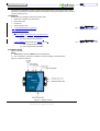
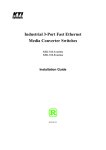
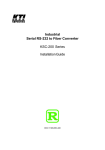
ABLELink® SE5001 Ethernet Serial Server Quick Start Guide Version 1.3 Updated on 2007/05/24 Tel: 886-3-5508137 Fax: 886-3-5508131 http://www.atop.com.tw Quick Start Guide Version 1.3 SE5001 Ethernet Serial Server 刪除: 1 This document is intended to provide customers with brief descriptions on the product and to assist customers to get started. For detail information and operations of the product, please refer to the user’s manual in the product CD. 1.Packaging Please check your package contains the following items: SE5001-S2 or SE5001-S5- Serial Server Quick Start Guide Product CD Wall mounting screws 3 pin terminal block for power input 格式化: 項目符號及編號 Optional Accessories: 1. DK-25 DIN-Rail Kit 2. Power Adapter with DC jack- PIN 1.3φ output 5V 1A (1) AD5V1A(US) Switching adapter (2) AD5V1A(EU) Switching adapter 3. Power Adapter with Terminal block output 12V1.25A (1) US315-12(US) Switching adapter (2) US315-12(EU) Switching adapter 2.Hardware Setup SE5001 interfaces NOTE: 1. SE5001-S2 (for RS-232), SE5001-5 (for RS-422/RS-485) 2. One can press the reset button of SE5001 to reset the settings to the default value Figure 2.1 shows the interfaces. Figure 2.1. SE5001 Interface Copyright © 2006 Atop Technologies, Inc. All rights reserved. Designed in Taiwan. 1 格式化: 項目符號及編號 Quick Start Guide Version 1.3 SE5001 Ethernet Serial Server 刪除: 1 LED Indicators: LAN LED Message Description Off Ethernet Disconnected Blinking with Green Data is transmitting on Ethernet for 100Mbps Blinking with Orange Data is transmitting on Ethernet for 10Mbps Table 1. LAN LED Message COM Port LED Message Description Off No data is transmitting on COM port Blinking Data is transmitting on COM port Table 2. COM Port LED Message RUN LED Message On Description Jumper JP1 Pin1 and Pin2 are shorted to disable AP firmware running Blinking (rate: 0.5 Sec) AP firmware is running normally Table 3. RUN LED Message Installation Procedures: Step 1: Connect SE5001 to power source using 5V DC Jack (or 9~30V DC Terminal Block power source) Note: SE5001 provide two power inputs can be connected simultaneously to live DC power sources. Anyone of the power inputs fails, the other live source acts as a backup to support power needs automatically. The redundant dual DC power inputs give you extra assurance of non-stop operation Step 2: Connect SE5001 to ones Ethernet network. Use a standard straight-through Ethernet cable when one connect it to a hub/switch, one also can connect it to ones PC‘s Ethernet port via a cross-over Ethernet cable for easy set up. However, in this case one need to make sure ones PC is in the same network sub-net as SE5001. Step 3: Connect SE5001’s serial port to a serial device. Step 4: Placement options. One can mount SE5001 to a wall/panel (Mounting screws included) or Din-Rail rack (Require optional item model: Din-Rail-Kit DK-25). 3. Software Setup Default Network Setting: Default User Name/Password: IP: 10.0.50.100 User Name: admin Gateway: 10.0.0.254 Password: null (leave it blank) Subnet: 255.255.0.0 Auto IP (Dynamic IP): A DHCP server can automatically assigns the IP address and network settings. SE5001 supports the DHCP function. By default, the DHCP function on SE5001 is disabled; you can use Monitor.exe to enable this function. (ref Figure 3.1) Copyright © 2006 Atop Technologies, Inc. All rights reserved. Designed in Taiwan. 2 刪除: putting a check on Auto IP on Dialog window. Quick Start Guide Version 1.3 SE5001 Ethernet Serial Server 刪除: 1 Figure 3.1. monitor.exe utility Dialog Window Assign a Static IP address by: A. Using Telnet 1. Telnet to SE5001 using DOS command “Telnet IP_address”. Example: telnet 10.0.50.100 2. SE5001’s network, link mode and COM ports settings can be configured in the telnet window B. Using Monitor.exe Utility Use Monitor.exe which comes inside the Product CD to automatically search for all SE5001 connected to ones local area network. Then please select the desired SE5001 to configure the network setting individually. C. Using Web Browser 1. Make sure ones PC is located on the same network sub-net as SE5001 2. 2Open a web browser, then type in the IP address of SE5001 to be configured. Default user name is admin and default password is null (leave it blank). 3. 3SE5001’s network, link mode and COM ports settings can be configured in different web pages. 4. Click “Save Configuration” to save settings. 5. Click ”Restart” button to make the change effective if necessary. 4. Pin Assignments The pin assignments of DB9 connector on SE5001 is shown in the following table: Pin# RS-232 Full Duplex for SE5001-S2 Model RS-485 2-wire Half Duplex for SE5001-S5 Model RS-422/RS-485 4-wire Full Duplex for SE5001-S5 Model 1 DCD N/A N/A 2 RXD N/A TXD+ 3 TXD DATA+ RXD+ 4 DTR N/A N/A 5 SG (Signal Ground) SG (Signal Ground) SG (Signal Ground) 6 DSR N/A N/A 7 RTS DATA- RXD- 8 CTS N/A TXD- 9 N/A N/A N/A Customer Services and Supports 1. Contact your local dealers or Atop Technical Support Center at the following numbers. y +886-3-550-8137 (Atop Taiwan) y +86-21-6495-6232 (Atop China) 2. Report the errors via Atop’s Web site or E-mail account www.atop.com.tw, [email protected] www.atop.com.cn, [email protected] Copyright © 2006 Atop Technologies, Inc. All rights reserved. Designed in Taiwan. 3