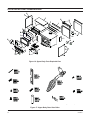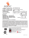
1
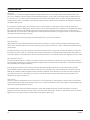
EPA APPROVED HIGH EFFICIENCY
AIR TIGHT WOOD STOVE
FOR RESIDENTIAL INSTALLATION
6" (152mm) Flue Required
MODELS:
SSW30FTAL, SSW30STAL, SSW30FTPB
SSW30FTAPB, SSW30STAPB
OWNERS MANUAL
We recommend that our products be installed and serviced
by professionals who are certified in the U.S. By NFI
(National Fireplace Institute) or in Canada by WETT
(Wood Energy Technical Training).
SAFETY NOTICE: Read this entire manual before you install and use your appliance. If not properly
installed, a house fire may result. To reduce the risk of fire, follow the installation instructions. Failure to
follow instructions may result in property damage, bodily injury, or even death. Contact local building, fire
officials or authorities having jurisdiction about permits, restrictions and installation inspection requirements in your area.
These units are mobile home approved for U.S. and Canada
CONTENTS
Specifications ................................................................... 03
Questions? ......................................................................... 04
Pre-installation instructions .............................................. 05
Unpacking and leg installation.......................................... 07
Stove set-up....................................................................... 09
Clearances ......................................................................... 11
Installation......................................................................... 12
Operation........................................................................... 14
Maintenance ...................................................................... 17
Replacement parts ............................................................. 20
Illustrated Parts Breakdown .............................................. 22
FAQs ................................................................................. 24
Warranty ............................................................. Back Cover
ACCESSORIES
2. Outside Air Termination Kit—Part no.: SSWOATK
3. Mobile Home Installation Kit—Part no.: SSWMHIK
4. Gold Legs—Part no.: SSW30CLGD
5. Gold Door Trim—Part no.: SSW30GDTK
WARNING
1. Variable Speed Blower—Part no.: BLOTWS
Proposition 65 Warning:
Fuels used in gas, woodburning or oil fired appliances, and the
products of combustion of such fuels, contain chemicals
known to the State of California to cause cancer, birth
defects and other reproductive harm.
California Health and Safety Code Sec. 25249.6
6. Nickel Legs—Part no.: SSW30CLN
7. Nickel Door Trim—Part no.: SSW30NDTK
8. Gasket Kit—Part no.: SSW30GK
9. Glass Door Kit—Part no.: SSW30GDK
10. Glass Door Handle Kit—Part no.: SSW30GDHK
11. Ash Pan Door Handle Kit—Part no.: SSW30AHK
12. Pedestal Ash Pan Door Handle Kit—Part no.:
SSW30APHK
13. Secondary Air Tubes Kit—Part no.: SSW30SAT
14. Baffle Insulation Kit—Part no.: SSW30BI
15. Brick Kit—Part no.: SSW30BK
16. Primary Air Module Kit—Part no.: SSW30PAM
INSTALLER
Please leave these instructions with the appliance.
OWNER
Please retain these instructions for future reference.
IMPORTANT
Read these instructions carefully before installing or trying to operating this woodburning appliance.
2
63D0001
SPECIFICATIONS
OVERALL DIMENSIONS
"G"
"A"
"B"
"F"
"A"
"C"
"D"
"E"
SSW30FTAL
MODEL
SSW30FTAL
SSW30STAL
A
30¼
33¾
SSW30STAL
B
28¼
28¼
"G"
C
19¼
19¼
D
24¼
24¼
G
27¾
27¾
"A"
"A"
"B"
"F"
"B"
"C"
"D"
"E"
"E"
SSW30FTPB
63D0001
F
NA
32
"G"
"A"
MODEL
SSW30FTPB
SSW30FTAPB
SSW30STAPB
E
26
26
SSW30STAPB
SSW30FTAPB
A
32¾
32¾
36¼
B
30¾
30¾
30¾
C
18½
19¾
19¾
D
24¼
24¼
24¼
E
25½
26⅜
26⅜
F
NA
NA
34½
G
27¾
27¾
27¾
3
QUESTIONS?
Log Length
Maximum burn time2
Average area heated (sq.ft)2
Range of heat output3
Maximum heat output1
EPA emissions rating (g/h, non-catalytic)
Weight
Loading
Air Control
20"
10 hours
2,200 sq. ft.
11,000-30,600
55,400
2.5 gph
520 lbs
Front
Manual
1. Maximum burn times and heat outputs are based on laboratory testing using full loads of seasoned hardwoods, and may vary in
individual use depending on how the stove is operated, type and moisture content of fuel, and other factors. Maximum burn times
are achieved under different operating conditions than are maximum heat outputs.
2. These values are based on operation in building code-conforming homes under typical winter climate conditions in the U.S. If your
home is of nonstandard construction (e.g. unusually well-insulated, not insulated, built underground, or if you live in a more severe
and more temperate climate), these figures may not apply. Since so many variables affect performance, consult your Lexington
Forge Authorized Dealer to determine realistic expectations for your home.
3. Under specific conditions used during EPA emissions testing.
NEED TO ASK QUESTIONS? REQUIRE PARTS INFORMATION?
First, contact the Lexington Forge Dealer from whom you purchased your stove, for parts and service. Have the following information
ready:
• Date of purchase
• Serial number (from the back of your stove)
• Model number (from the back of your stove)
• Dealer name and phone
If you still need assistance, contact Lexington Forge technical support (below).
WONDERING ABOUT THE WARRANTY?
See the last page of this manual for general warranty information. For additional information, contact your Lexington Forge dealer or
Lexington Forge Parts and warranty.
Lexington Forge
Technical Service, Parts & Warranty
Phone: 877-406-9180
Fax: 877-406-5647
Model and product serial numbers can be found on the certification label of your stove.
4
63D0001
CAUTION
PRE-INSTALLATION INSTRUCTIONS
After reading these instructions, if you have any doubt about your ability to complete your installation in
a professional like manner, you should obtain the services of an installer versed in all aspects as to the
correct and safe installation. DO NOT use temporary, makeshift compromises during installation.
BEFORE INSTALLATION OF YOUR APPLIANCE
1.
2.
3.
4.
5.
6.
7.
8.
Check with the building inspector’s office for compliance with local codes; a permit may be required.
This appliance requires a masonry or prefabricated chimney listed to ULC S629 (Canada) and UL 103HT (U.S.) sized correctly.
A 6" (152mm) diameter flue is required for proper performance.
Always connect this unit to a chimney and NEVER VENT TO ANOTHER ROOM OR INSIDE A BUILDING.
DO NOT connect this unit to any duct work to which another appliance is connected such as a furnace.
DO NOT connect this unit to a chimney flue serving another appliance.
The connector pipe and chimney should be inspected periodically and cleaned if nescessary.
Remember the clearance distances when you place furniture or other objects within the area. DO NOT store wood, flammable
liquids or other combustible materials too close to the unit. Refer to certification label on back of your unit for required
clearances.
9. Contact your local municipal or provincial fire authority for information on how to handle a chimney fire. Have a clearly
understood plan to handle a chimney fire. In the event of a chimney fire, turn air control to closed position and CALL THE
FIRE DEPARTMENT.
10. DO NOT tamper with combustion air control beyond normal adjustment.
11. If installing in a mobile home, use mobile home kit.
WHY THE CORRECT FLUE SIZE IS IMPORTANT — 6" (152 MM)
Draft is the force, which moves air from the appliance up through the chimney. The amount of draft in your chimney depends on the
length of the chimney, local geography, nearby obstructions, and other factors. Too much draft may cause excessive temperatures in
the appliance. An uncontrolled burn, a glowing red part or chimney connector indicates excessive draft. Inadequate draft may cause
back puffing into the room and “plugging” of the chimney and/or cause the appliance to leak smoke into the room through appliance
and chimney connector joints.
Today’s solid fuel appliances are much more efficient than in the past. The units are designed to give you controlled combustion, as
well as maximum heat transfer, using less fuel to do so. The design of your new appliance is such that the exhaust “smoke” is now at
lower temperatures than in the past, therefore requiring proper chimney size to give adequate draft. If your chimney is too large, the
heating appliance will have a difficult time to raise the “chimney flue” temperature to give adequate draft, therefore causing a smoke
back up, poor burn, or both.
Should you experience such a problem call in a local chimney expert.
With the door closed, the rate of burning is regulated by the amount of air allowed to enter the unit through the air control. With
experience you will be able to set the control for heat and burning time desired.
Once the required chimney draft is obtained, operate only with doors closed and open slowly when re-fueling. (This will reduce or
eliminate smoke from entering the room.)
63D0001
5
CAUTION
CAUTION
THIS HEATER IS EXTREMELY HOT WHILE IN OPERATION.
SERIOUS BURNS CAN RESULT FROM CONTACT.
KEEP CHILDREN, PETS, CLOTHING AND FURNITURE AWAY
Attempts to achieve higher output rates that exceed heater design specifications can result in permanent damage to the heater. The
recommended wood load is level with the top of the firebricks. Overloading may prevent sufficient air entering the heater to properly
fuel the fire.
Important: For optimum heater performance at “low” burn rate, operate the fan at low speed.
An outside air kit is available from your Lexington Forge dealer.
Optional Blower: 70v 130 CFM
Model: BLOTWS
• OPERATE THIS HEATER ONLY WITH THE DOOR CLOSED.
• DO NOT BURN GARBAGE OR FLAMMABLE FLUIDS.
DANGER
• DO NOT USE CHEMICALS OR FLUIDS TO START THE FIRE.
6
RISK OF ELECTRIC SHOCK.
DISCONNECT POWER BEFORE
SERVICING UNIT.
63D0001
UNPACKING AND ATTACHING LEGS
REMOVING THE STOVE FROM THE PALLET AND ATTACHING THE LEGS ON THE SSW30(F/S)TAL
Caution: Stove is extremely heavy. You will need help installing the legs and moving your stove to its final
location.
Please note: The fiberboard baffle is secured with two screws for shipping purposes only. These screws are
located behind the rear tube and may be removed prior to use, if so desired.
The legs are packed inside the stove with bolts for assembling legs to the stove. Useful note: If you misplace the bolts in the leg pack,
the bolts used to hold the shipping bracket to the stove can be used to hold the legs in place.
Tools required: 7/16" & 9/16" wrench or socket.
1) Remove the foam leg pack from inside your stove. The pack should contain 4 legs and 8 bolts.
2) To begin the leg installation remove the bolts from the hold down brackets from the pallet only. This is so you will be able to
move the stove to the edge of the pallet and install the legs one at a time. (9/16" wrench or socket.) Figure 1
3) Slide the stove so that a rear corner of the stove is extended past the edge of the pallet just enough to install rear leg. Figure
2
Figure 1
Figure 2
4) Remove both bolts from the rear leg location of the hold down bracket and one of the bolts from the front leg location of the
same hold down bracket. (7/16" wrench or socket.)
5) Swing hold down bracket out from stove just far enough to install rear leg. Figure 3
6) Use the bolts provided to install the rear leg. (7/16" wrench or socket.) . Figure 4
Figure 3
63D0001
Figure 4
7
UNPACKING AND ATTACHING LEGS
7) With rear leg installed, pivot the stove so that the hold down bracket is off the pallet. The stove should be resting the installed
leg on the floor, one support bracket on the pallet and the partially loosened support bracket hanging free. Have someone
steady the stove to avoid tipping.
8) Remove the remaining bolt from the hold down bracket and install front leg. Figures 5 & 6
9) Pivot the stove or twist the pallet so the rear corner of the remaining support bracket is extended over the pallet just far
enough to install the rear leg.
Figure 5
Figure 6
10) Remove both of the bolts from the top rear section of the hold down bracket and one of the bolts from the top front section of
the hold down bracket.
11) Pivot the hold down bracket out of the way just far enough to install the other rear leg.
12) Pivot the stove or slide the pallet so that the three installed legs are on the floor and the stove is completely off the pallet.
13) Remove the final remaining bolt from the hold down bracket and install the final leg.
Figure 7
Figure 8
8
63D0001
STOVE SET-UP
STOVE SET-UP
1.
2.
3.
Check that all brick and tubes are in place.
Select the proper location for the stove. These appliances must not be installed any closer than the minimum clearance to
combustible materials shown on page 11 of this manual. The stove must be installed on a non-combustible surface as shown on
page 11 of this manual.
Remove packing material and packing labels from glass.
FAILURE TO FOLLOW THE MINIMUM CLEARANCE REQUIREMENT AND NON-COMBUSTIBLE SURFACE
REQUIREMENTS MAY RESULT IN AN UNSAFE INSTALLATION
4.
5.
6.
If non-combustible materials have been installed on the walls, obtain the minimum clearances from either the manufacturer of
these materials or the local building inspectors office.
Install the stovepipe INSIDE the flue collar on the top of the stove between the stove and chimney.
DO NOT use a grate to elevate the fire.
STOVE PIPE
1.
2.
3.
4.
5.
6.
7.
8.
Make sure your chimney and chimney connector meets safety codes. Check with authorities having jurisdiction in your area.
All pipe sections must be connected with the male end (crimped end) toward the stove.
Fasten the stove pipe to the flue collar by the use of three sheet metal screws. Do the same at each additional joint to make the
entire installation rigid.
Maintain the required diameter flue for the entire installation.
If you are connecting the stove to an old masonry flue, be sure to have it inspected for cracks and general condition. Resizing
with a stainless steel liner may be required.
It is recommended that no more than two 90 degree bends be used in the stovepipe installation. More than two 90 degree bends
may decrease the amount of draw and possible cause smoke spillage.
A damper is not required in this installation. Remove any damper plate in the chimney or secure in the OPEN position.
Single wall flue pipe assemblies must not exceed 10 feet (3 meters) in overall length.
NOTES ON CHIMNEY AND STOVEPIPE INSULATIONS:
Maintaining a clean chimney is important. Chimneys should be inspected regularly for creosote buildup. A straight chimney is easier
to clean than one with 45 or 90 degree bends. A bend requires the pipe to be removed for cleaning. The stove baffle must be removed
when cleaning the chimney. Chimney sweepings will build up on top of baffle causing a blocked flue and/or a fire hazard.
Steel Chimney
Most factory made “Class A” steel chimneys have a layer of insulation around the inner flue. This insulation keeps the smoke warm
and protects the surrounding structure from the high flue temperatures. Because the insulation is less dense than masonry, the inner
steel liner warms up more quickly than masonry chimney; this makes the steel chimney support a good draft more quickly than
masonry does.
Indoor/Outdoor Location
Because the chimney’s function is to keep the smoke warm, it is best to locate it inside the house. This location uses the house as
insulation for the flue and allows some radiant heat release form the flue into the home. Since an interior chimney doesn’t continuously
lose its heat to the outdoors, less heat from the stove is required to get it warm and keep it warm.
63D0001
9
STOVE SET-UP
Flue Sizing
The flue size for a controlled-combustion appliance should be based on the cross-sectional volume of the stove flue outlet. In this
case, more is definitely not better. Hot gases lose heat through expansion; if a stove with a six-inch flue collar (28 square inch area)
is vented into a 10" x 10" flue, the gases will expand to over three times their original volume. As gases cool with expansion, draft
strength decreases. If the oversized flue is also outside the house, the heat it absorbs will be conducted to the outdoor air and the flue
will remain relatively cool.
It is common for a masonry flue to be oversized for the stove. Such a chimney can take quite a while to warm up, and the stove
performance will likely be disappointing. The best solution to an oversize flue problem is the installation of an insulated steel chimney
liner of the same diameter as the appliance flue outlet. The liner keeps the exhaust gas warm and the result is a stronger draft. An
uninsulated liner is a second choice—although the liner will keep the exhaust restricted to its original volume, the air around the liner
will require time and heat energy to warm up.
Check your local codes. You may be required to install a flue liner in any oversize masonry flue.
Masonry Chimney
Although masonry is the traditional material used for chimney construction, it can have distinct performance disadvantages when
used to vent a controlled combustion wood stove. Masonry forms an effective “heat sink”—that is, it absorbs and holds heat for long
periods of time.
The large mass however, may take a long time to become hot enough to sustain a strong draft. The larger the chimney (in total mass)
the longer it will take to warm up. Cold masonry will actually cool exhaust gases enough to diminish draft strength. This problem is
worse if the chimney is located outside the home or if the chimney flue has a cross-sectional volume much larger than the stove outlet.
Pipe and Chimney Layout
Every bend in the flue will act as a brake on the exhaust as it flows from the firebox to the chimney cap. The ideal pipe and chimney
layout is straight up from the stove through completely straight chimney. Use this layout if at all possible, as it will promote optimum
stove performance and simplify maintenance.
If the stovepipe must elbow to enter a chimney, locate the elbow about midway between the stovetop and the chimney thimble.
This configuration lets the smoke speed up before it must turn, keeps some pipe in the room for heat transfer, and allows long-term
flexibility for installing a different appliance without relocating the thimble. There should be no more than eight feet of single-wall
stove pipe between the stove and a chimney. Longer runs can cool the smoke enough to cause draft and creosote problems. Use
double-wall stove pipe for longer runs.
Single Venting
Your stove requires a dedicated flue. Do not connect the stove to a flue used by any other appliance. Chimney draft is a natural form
of energy and follows the path of least resistance. If the stove is vented to a flue that also serves open replace or another appliance, the
draft will also pull air through those avenues.
The additional airflow will lower the flue temperatures, reduce draft strength and promote creosote development; overall stove
performance will suffer. The effect is similar to that of a vacuum cleaner with a hole in the hose. In some extreme instances, the other
appliances can even impose a negative draft and result in a dangerous draft reversal.
10
63D0001
CLEARANCES
CLEARANCES TO COMBUSTIBLES (UL-1482 AND ULC-S627)
Minimum clearances to combustible materials in inches. Note: All “A,” “C,” and “F” dimensions are to the stove pipe.
A
B
C
D
E
F
G
14.5
11.5
11
8
21.5
18.5
11
8
7
5.5
16.75
15.25
NA
NA
10.5
10.5
7
7
17.5
17.5
7
7
7
5.5
16.75
15.25
NA
NA
Installation: 90° elbow off top of stove through back wall
Single Wall Pipe
Flat top model
14.5
11
21.5
Step top model
14.5
11
21.5
11
11
NA
NA
NA
NA
14
14
Installation: Full Vertical
Single Wall Pipe
Flat top model
Step top model
Double Wall Pipe
Flat top model
Step top model
H
I
14
14
11
8
Installation: Alcove—Six inch (6") (152mm) diameter listed doube wall air insulated connector pipe with UL 103 HT listed factorybuilt Class “A” chimney, or a masonry chimney. (Mobile home must be equipped with a spark arrestor). Maximum depth of alcove
shall be no more than 48" (1220mm). Please refer to NFPA 211.
Double Wall Pipe
Flat top model
NFPA min.
Step top model
NFPA min.
B
A
C
H
D
G
E
F
F
E
Figure 9: Clearances to Combustibles
63D0001
11
INSTALLATION
WALL PASS-THRUS
Whenever possible, design your installation so the connector does not pass through a combustible wall. If you must use a wall passthrough in your installation, check with your building inspector before you begin and construct it in accordance with local building
codes. Also, check with the chimney connector manufacturer for any specific requirements.
Accessories are available from your dealer for use as wall pass-throughs. If using one of these, make sure it has been tested and listed
for use as a wall pass-through.
All combustible material in the wall is cut away a sufficient distance from the single-wall connector to provide the required 12"
(305mm) clearance for the connector. Any material used to close up the opening must be non-combustible.
The following wall pass-through methods may be approved in your area:
•
•
•
Use a section of listed factory-built chimney with a nine-inch clearance to combustibles.
Place a chimney connector pipe inside a ventilated thimble, which is then separated from combustibles by 6"(152 mm) of
fiberglass insulating material.
Place a chimney connector pipe inside a section of listed solid-insulated, factory-built chimney, with an inside diameter
1" (51 mm) larger than the chimney connector and having 1" (25mm) or more of insulation and maintaining a minimum
2 inch air space between the outer wall of the chimney and combustibles.
)
MM
"
12
5
(30
18" (450MM)
CHIMNEY
EMPTY SPACE ALL
CONNECTOR
AROUND THE CHIMNEY
CONNECTOR
SHEET METAL
COVER (THIS
SIDE ONLY)
)
MM
05
" (3
12
Figure 10: Wall pass-thru
enclosed with noncombustible
materials
Figure 11: Hollow wall pass-thru
12
63D0001
INSTALLATION
Do not connect the heater to any air distribution duct or system.
In Canada: The Canadian Standards Association has established different guidelines. Figure 11 shows one method, in which all
combustible material in the wall is cut away to provide the required 18" (450 mm) clearance for the connector. The resulting space
must remain empty.
A flush mounted sheet metal cover may be used on one side only. If covers must be used on both sides, each cover must be mounted
on non-combustible spacers at least 1" (25mm) clear of the wall. Your Lexington Forge dealer or your local building inspector can
provide details of other approved methods of passing a chimney connector through a combustible wall. In Canada, this type of
installation must conform to CAN/CSA-B365. Installation Code for Solid Fuel Burning Appliances and Equipment.
NOTE: Do not vent your stove into a factory-built (zero-clearance) fireplace. These appliances and their chimneys are specifically
designed as a unit for use as fireplaces. It may void the listing or be hazardous to adapt them for any other use.
FLOOR PROTECTOR
Installation on a Concrete Floor
An appliance mounted on a concrete floor does not require floor protection.
Carpeting and any other combustible material shall not cover the floor protector.
If a combustible surface is applied to the concrete floor, a clearance must be maintained equivalent to the area reserved for the floor
protector. See Figure 12.
Installation on a Combustible Floor
If the appliance is to be installed on a combustible floor or a combustible floor covering, it must be installed on a 3/8" (10mm) thick
non-combustible millboard floor protector or durable equivalent. The pad must be installed beneath the appliance extending 18" (457
mm) in Canada, 16" (406mm) in the U.S. on any side equipped with a door, and 8" (203mm) on all other sides. In the U.S. the pad
must cover any horizontal chimney connector runs and extend 2" (51mm) beyond each side.
2" (51MM)
2" (51MM)
WALL LINE
8" (203MM)
FLOOR
PROTECTOR
8" (203MM)
8" (203MM)
18" (457MM)
16" (406MM)
DOOR SIDE OF
APPLIANCE
CANADA
U.S.A.
Figure 12: Installation on a combustible floor
63D0001
13
OPERATION
CHIMNEY
REFER TO CHIMNEY AND CHIMNEY CONNECTOR MANUFACTURER’S INSTRUCTIONS
Contact your local building authority for approved methods of installation
1.
2.
3.
4.
This appliance requires a masonry or pre-manufactured chimney listed to ULCS629 (Canada) and UL 103 HT (USA) sized
correctly.
If a masonry chimney is used it is advisable to have your chimney inspected for cracks and check the general condition before you
install your unit. Re-lining may be required to reduce flue diameter to the appropriate functional size.
The chimney should extend at least 3' (914 mm) above the highest point where it passes through the roof, and at least 2' (610 mm)
higher than any portion of a building within 10' (3 m). Figure 13.
The chimney connector shall not pass through an attic, roof space, closet, concealed space, floor, ceiling, wall or any partition of
combustible construction.
0 TO 10'
2' Min.
0 TO 10'
3' Min.
2' Min.
3' Min.
Reference
Point
Figure 13: The 2'-3'-10' Chimney Rule
5.
6.
The minimum overall height of your chimney should be 15' (5M) from the floor.
Do not use makeshift compromises during installation.
At the very least, inspect the chimney connector and chimney at least once every two months during the heating season to determine
if a buildup of creosote or soot has occurred. If a significant layer of creosote has accumulated (1/8" (3mm) or more], or if soot has
accumulated, either should be removed to reduce the risk of a chimney fire. Failure to keep the chimney and connector system clean
can result in a serious chimney fire.
The conditions for a chimney fire develop as follows: When wood is burned slowly, it produces tar and other organic vapors which
combine with expelled moisture to form creosote. The creosote vapors condense in the relatively cool chimney flue of a slow burning
fire. As a result creosote residue accumulates on the flue lining. Creosote is a flammable and, when ignited, make an extremely hot fire
within the flue system which can damage the chimney and overheat adjacent combustible material.
To reduce the amount of creosote that may form, remember to provide adequate air for combustion and to strive for small, intense fires
rather than large smoldering ones.
14
63D0001
OPERATION
You can never be too safe. Contact your local fire authority for information on what to do in the event of a chimney fire, and have a
clearly understood plan on how to handle one.
OPERATION
Do not use a grate or elevate fire. Build wood fire directly on firebrick. When the stove is used for the first time the solvents in the
paint will smoke off.
Wood
This heater is designed to burn natural wood only. Higher efficiencies and lower emissions generally result when burning air dried
seasoned hardwoods, as compared to softwoods or to green or freshly cut hardwoods.
Only use dry seasoned wood. Green wood, besides burning at only 60 percent of the fuel value of dry wood, deposits creosote on the
inside of your stove and along the chimney. This can cause an extreme danger of chimney fire. To be called “seasoned,” wood must
be dried for a year. Regardless of whether the wood is green or seasoned, it should be stored in a well-sheltered ventilated area to
allow proper drying during the year to come. Wood should be stored beyond recommended clearance from combustibles.
Fuel
Even the best stove installation will not perform well with poor fuel. If available, always use hardwood that has been air-dried
(seasoned) 12-18 months. Softwood burns more rapidly than hardwood and has a high pitch content that can result in creosote.
Decayed wood of any type has little heat value and should not be used.
Unseasoned (green) wood has a high moisture content. Much of its heat value will be used to evaporate moisture before the wood can
burn. This significantly reduces the amount of energy available to warm your home, as well as the intensity of the fire and temperature
of the exhaust gas. Incomplete combustion and cool flue temperatures promote creosote formation and weak draft.
You can judge the moisture content of wood by its appearance and weight or use a commercially available moisture meter for exact
measurement. Unseasoned wood will be a third heavier than dry wood. Also look for cracks (checking) in the ends of the log that
result from contraction as the wood dries. The longer and wider the cracks are, the dryer the wood is.
Creosote
Creosote is a by-product of low-temperature stove operation, weak draft or both. It is a tar that results when unburned gases condense
inside the flue system at temperatures below 290 degrees F. Creosote is volatile and can generate a chimney fire. All of the installation
characteristics that adversely affect chimney draft also promote creosote condensation. Consequently, you can minimize creosote
accumulation with an effective chimney design and the use of operational techniques that encourage good draft and complete
combustion.
Inspect your chimney frequently and clean it whenever accumulation exceeds 1/4".
DO NOT BURN: Treated Wood, Solvents, Trash, Coal, Garbage, Cardboard, Colored Papers
NEVER USE GASOLINE, GASOLINE-TYPE LANTERN FUEL, KEROSENE, CHARCOAL LIGHTER FLUID, OR
SIMILAR LIQUIDS TO START OR “FRESHEN UP” A FIRE IN THIS HEATER. KEEP ALL SUCH LIQUIDS WELL
AWAY FROM THE HEATER WHILE IT IS IN USE
63D0001
15
OPERATION
INSTRUCTION FOR FIRST BURN – CURING THE STOVE PAINT
Your stove has been painted with the highest quality stove paint and has special break-in procedures. The heat generated by the
normal operation of the stove, will serve to harden the paint.
Ventilate the house during the first three times the stove is used. The paint on the stove will give off smoke, carbon dioxide and an
odor. Without adequate ventilation, concentrations of smoke could irritate, or be upsetting. Open doors and windows and use a fan
if necessary. After the initial burns the paint will be cured and there should be no more smoke. Each of the initial burns should be
conducted as follows:
A) The first 2 burns should be at approximately 250° F (120° C) for approximately 20 minutes.
B) The 3rd burn should be between 500° F and 700° F (260° to 370° C) for at least 45 minutes. The important fact is the paint should
be cured slowly. Avoid hot fires during the curing process.
The best way to achieve the first burn is with kindling fires. Prolong the fires as needed by adding more kindling. During the curing
process the paint may be gummy. Once cured the paint will remain hard. It is normal to see flat spots on painted surfaces of the
stove. The flat spots on the paint surface indicate the hotter surfaces of the stove, and is caused by the heat radiating through the paint.
It is also expected that shiny spots caused by friction from the packaging materials, will disappear during the curing of the stove.
So . . .
1)
2)
3)
4)
5)
Remember to ventilate well.
Allow the stove to cure before burning for long periods at high temperatures.
Flat spots on the painted surfaces are normal.
Shiny spots on the paint surface before burning is normal.
Call your dealer if you have any questions.
BUILDING A FIRE
1.
2.
3.
4.
5.
Open inlet air control fully.
Place a small amount of crumpled paper in the stove.
Cover the paper with a generous amount of kindling wood in a teepee fashion and a few small pieces of wood.
Ignite the paper and close door. If fire dies down substantially, open door slightly.
Add larger pieces of wood as the fire progresses being careful not to overload. Do not fill firebox beyond firebrick area. An ideal
coal bed of 1" (25mm) to 2" (50mm) should be established to achieve optimum performance.
6. This unit is designed to function most effectively when air is allowed to circulate
to all areas of the firebox. An ideal means of achieving this is to rake a slight (1" to
2" wide) trough in the center of the coal bed from front to back prior to loading the
fuel.
7. Once fuel has been loaded, close door and open air inlet control fully until fire is
well established (approx. 10 minutes) being careful not to over fire.
8. Re-adjust air inlet control to desired burn rate. If excessive smoke fills firebox,
open air inlet control slightly until flames resume and wood is sufficiently ignited. A
basic rule of thumb is “closed – low,” “½ way-medium,” and “fully open – high.”
9. When refueling, adjust air control to the fully open position. When fire
brightens, slowly and carefully open the door. This procedure will prevent gases
from igniting causing smoke and flame spillage.
10. Add fuel being careful not to overload.
A
Low burn
16
High burn
Figure 18: Air Control Layout
63D0001
MAINTENANCE
REMOVING BAFFLE:
1. Pull the cotter pin from the retaining collar on the front tube. See Detail A.
2. Tilt up the front side of the baffle and insulation.
3. Slide the tube to the right to free from the collar, tilt down and push towards the left, then pull out the tube. See Figure
15.
4. Work baffle and insulation from top of stove.
NOTE: When reinstalling baffle make sure the baffle stops at the edge of center baffle plate. See Detail B.
SECTION RIGHT SIDE VIEW
2.
1.
A
Step 1: Pull the cotter pin from the
retaining collar on the front tube.
Step 2: Tilt up the front side of
the baffle and insulation
4.
Detail A
Step 4: Work baffle and insulation
from top of the stove
3.
C
B
NOTE: When reinstalling baffle
make sure the baffle stops at
the edge of center baffle plate.
Step 3: Slide the tube to
the right to free from the
collar, tilt down and push
towards the left then pull
out the tube.
Detail B
Figure 15: Removing Baffle
63D0001
17
MAINTENANCE
REMOVING FIREBRICK
To remove firebrick, lift up from bottom and rotate outward. See Figure 14.
GLASS CARE
REPLACE GLASS ONLY WITH HIGH TEMPERATURE CERAMIC
AVAILABLE FROM YOUR LOCAL LEXINGTON FORGE DEALER
The following use and safety tips should be observed:
1.
2.
3.
4.
5.
6.
Firebrick
Inspect the glass regularly for cracks and breaks. If you detect a crack
Figure 14: Removing Firebrick
or break, extinguish the fire immediately, and contact your dealer for
replacement.
Do not slam door or otherwise impact the glass. When closing doors, make sure that logs or other objects do not protrude to
impact the glass.
Do not clean the glass with materials which may scratch (or otherwise damage) the glass. Scratches on the glass can develop into
cracks or breaks.
Never attempt to clean the glass while unit is hot. Light deposits are normal. Heavier deposits may be removed with the use of a
readily available oven cleaner.
Never put substances which can ignite explosively in the unit since even small explosions in confined areas can blow out the
glass.
This unit has an air wash systems, designed to reduce deposits on glass.
GASKET REPLACEMENT
After extensive use, the sealing material which provides glass and door seal may need to be replaced if it fails to sustain its resilience.
Inspect glass and door seal periodically to ensure proper seal: if gaskets become frayed or worn, replace immediately. Contact your
dealer for approved replacement parts. Refer to replacement parts list in this manual.
The following steps should be followed for glass gasket replacement:
1. Ensure appliance is not in operation and is thoroughly cooled
2. Remove screws and glass clips.
3. Lift glass out.
4. Remove old gasket and clean glass.
5. Replace new gasket starting at the bottom of glass working along edges, being sure to center gasket channel on glass.
6. Trim to length and butt ends together.
7. Replace glass in door, being sure not to over-tighten screws and clips.
The following steps should be followed for door gasket replacement:
1. Ensure appliance is not in operation and is thoroughly cooled.
2. Remove old door gasket and clean channel.
3. Using an approved high temperature gasket cement, apply a thin coat in bottom of channel.
4. Starting at hinge side of door, work into channel around door unit, end butt and trim to length.
5. Close door and allow three to four hours for cement to set before restarting appliance.
18
63D0001
MAINTENANCE
CREOSOTE
When wood is burned slowly, it produces tar and other organic vapors. These combine with moisture to form creosote. Creosote
vapors condense in the relatively cool chimney flue of a slow burning fire. As a result, creosote residue accumulates on the flue lining.
When ignited, this creosote makes an extremely hot fire. The chimney should be inspected regularly during the heating season to
determine if a creosote build-up has accumulated. If this is the case, the creosote should be removed to reduce the risk of chimney
fire.
WARNING:
Things to remember in case of chimney fire:
1. CLOSE DRAFT CONTROL
2. CALL THE FIRE DEPARTMENT
KEEP UNIT FREE OF CREOSOTE
1. Burn with air control open for several minutes at numerous intervals throughout the day during the heating season, being careful
not to over-fire unit. This removes the slight film of creosote accumulated during low burn periods.
2. Burn stove with draft control wide open for several minutes every time you apply fresh wood. This allows wood to achieve the
charcoal stage faster and burns wood vapors which might otherwise be deposited within the systems.
3. BURN ONLY SEASONED WOOD. Avoid burning wet or green wood. Seasoned wood has been dried for at least one year.
4. A small hot fire is preferable to a large smoldering one that can deposit creosote within the system.
5. Establish a routine for the fuel, wood burner and firing technique. Check daily for creosote build-up until experience shows how
often you need to clean to be safe. Be aware that the hotter the fire, the less creosote is deposited and weekly cleaning may be
necessary in mild weather even though monthly cleaning may be enough in the coldest months. Contact your local municipal
authority for information on how to handle a chimney fire. Have a clearly understood plan to handle a chimney fire.
ASH DISPOSAL
Ashes should be placed in a metal container with a tight-fitting lid. The closed container of ashes should be placed on a noncombustible floor or on the ground, well away from all combustible materials, pending final disposal. If the ashes are disposed of by
burial in soil or otherwise locally dispersed, they should be retained in the closed container until all cinders have thoroughly cooled.
Other waste should not be placed in the ash container.
63D0001
19
REPLACEMENT PARTS
SSW30
SSW30
SSW30
SSW30
SSW30
FTAL
FTAPB
STAL
STAPB
FTPB
ITEM
PART No.
Description
Qty.
1
63D0162
FIREBRICK
14
14
14
14
14
15
2
63D0028
SECONDARY- AIR ROUNDTUBINGREAR
1
x
x
x
x
x
3
63D0026
SECONDARY- AIR ROUNDTUBINGMIDDLE
1
x
x
x
x
x
4
63D0112
SECONDARY-AIR ROUND TUBINGFRONT
1
x
x
x
x
x
5
63D0022
COTTER PIN 3/32” DIA. X 1.25 LG.
3
x
x
x
x
x
6
63D0159
REAR INSULATION 1” X 2” X 24”
1
x
x
x
x
x
7
63D0160
BAFFLE INSULATION 1” X 12” X 24”
1
x
x
x
x
x
8
63D0181
C-CAST HD FIBER BOARD-MED
1
x
x
x
x
x
9
63D0167
CAST IRON AIR WASH MANIFOLD
1
x
x
x
x
x
10
63D0302
3/8” ROPE GASKET
11
63D0304
1/4”-20 X 1” BUTTON HEAD CAP SCREW
12
63D0128
CAST IRON PRIMARY AIR COVER
13
63D0302
3/8” ROPE GASKET
14
63D0019
PRIMARY AIR COVER TUBE BRACKET
1
x
x
x
x
x
15
63D0076
#10-24 X 3/8” PPH SCREW
4
x
x
x
x
x
16
63D0304
1/4”-20 X 1” BUTTON HEAD CAP SCREW
2
x
x
x
x
x
17
63D0117
AIR MODULE ASSEMBLY-MED
1
x
x
x
x
x
18
63D0304
1/4”-20 X 1” BUTTON HEAD CAP SCREW
2
x
x
x
x
x
19
63D0065
1/4”-20 X 1/2 FLAT HEAD SOCKET CAP
SCREW
2
x
x
x
x
x
20
63D0068
CAST IRON GRATE-MED
1
x
x
x
x
21
63D0171
SIDE FILLER
2
x
x
x
x
22
63D0187
CAST IRON DOOR
1
x
x
x
x
x
23
63D0164
DOOR BEZEL
1
x
x
x
x
x
24
63D0107
#10-24 X 1” SOCKET HEAD CAP SCREW
x
25
63D0300
3/4” ROPE GASKET
26
63D0111
CERAMIC GLASS DOOR W/ IR COATED
27
63D0301
1/4” ROPE GASKET
28
63D0174
GLASS CLIP
29
63D0076
4MM x 28.5MM FHMS
8
x
x
x
x
x
30
63D0313
ASSEMBLY GLASS DOOR HANDLE
1
x
x
x
x
x
31
63D0183
3/8” DIA. X 2” LG HINGE PIN
2
x
x
x
x
x
32
26D3320
SNAP DISK BRACKET
1
x
x
x
x
x
33
0052825B
#8 X 1/2” PAN PHILLIP HEAD SHEET
METAL SCREW
2
x
x
34
63D0195
WELDMENT REAR SHIELD MED
1
x
x
x
x
x
35
58D6022
1/4”-20 X 3/8” LG. BUTTON HEAD
SOCKET CAP SCREW
4
x
x
x
x
x
36
63D0006
OUTER WRAPPER SIDE-LEFT
1
x
x
x
x
x
37
63D0030
OUTER WRAPPER SIDE-RIGHT
1
x
x
x
x
x
38
0052825B
#8 X 1/2” PAN PHILLIP HEAD SHEET
METAL SCREW
6
x
x
x
x
x
39
63D0020
ADJUSTABLE REAR SHIELD
1
x
x
20
4 1/2 FT.
x
x
x
x
x
2
x
x
x
x
x
1
x
x
x
x
x
4 1/2 FT.
x
x
x
x
x
x
10
x
x
x
x
5 FT.
x
x
x
x
x
1
x
x
x
x
x
4 1/2 FT.
x
x
x
x
x
4
x
x
x
x
x
x
x
63D0001
REPLACEMENT PARTS CONTINUED
SSW30
SSW30
SSW30
SSW30
SSW30
FTAL
FTAPB
STAL
STAPB
FTPB
x
ITEM
PART No.
Description
40
58D6022
1/4”-20 X 3/8” LG. BUTTON HEAD
SOCKET CAP SCREW
2
x
41
63D0186
CAST IRON LEGS
4
x
x
42
63D0330
6mm X 25mm LEVELLER
4
x
x
43
63D0063
1/4 FLAT WASHER
8
x
x
44
63D0064
1/4”-20 X 1” STANDARD HEX HEAD
BOLT
8
x
x
45
63D0089
WELDMENT ASH DOOR HINGE MOUNTING BRKT
1
x
x
46
58D6022
1/4"-20 X 3/8" LG. BUTTON HEAD
SOCKET CAP SCREW
3
x
x
47
63D0385
WELDMENT ASH DOOR HINGE BRKT
1
x
x
48
63D0080
ASH PAN MED
1
x
x
49
63D0188
CAST IRON ASH PAN DOOR
1
x
x
50
63D0302
3/8” ROPE GASKET
2.833 FT.
x
x
51
63D0097
1/4 DIA. X 2.875 LG. HINGE PIN
1
x
x
52
63D0067
3/32” DIA. X 1/2” LG COTTER PIN
1
x
x
53
63D0314
ASSEMBLY ASH PAN DOOR HANDLE
1
x
x
54
63D0165
CAST IRON PEDESTAL BASE
1
x
x
55
63D0330
6mm X 25mm LEVELLER
4
x
x
56
63D0344
1/4”-20 X 3/4” STANDARD HEX HEAD
BOLT
4
x
x
57
63D0166
CAST IRON PEDESTAL ASH PAN DOOR
1
x
x
58
63D0302
1/2” ROPE GASKET
3.5 FT.
x
x
59
63D0066
#10-24 X 1/4” SOCKET HEAD CAP
SCREW
4
x
x
60
63D0318
ASSEMBLY PEDESTAL ASH PAN DOOR
HANDLE
1
x
x
61
63D0321
WELDMENT PEDESTAL ASH PAN
1
x
x
63D0001
Qty.
x
21
ILLUSTRATED PARTS BREAKDOWN
38
36
7
39
40
5
8
6
11
A
9
10
B
29
2
28
3
E
4
35
L
62
25
34
26
1
30
21
G
16
32
33
20
31
F
H
27
J
K
24
22
23
14
13
15
C
38
17
12
19
18
D
37
Figure 16: Upper Body Parts Exploded View
DETAIL A
SCALE = 5:1
63D0022
DETAIL E
SCALE = 5:1
63D0174
DETAIL B
SCALE = 5:1
63D0304
DETAIL C
SCALE = 5:1
63D0076
DETAIL D
SCALE = 5:1
63D0065
DETAIL K
SCALE = 5:1
0052825B
DETAIL H
SCALE = 5:1
63D0313
DETAIL F
SCALE = 5:1
63D0107
DETAIL G
SCALE = 5:1
63D0183
DETAIL L
SCALE = 5:1
58D6022
DETAIL J
SCALE = 5:1
26D3320
Figure 17: Upper Body Parts Detail View
22
63D0001
ILLUSTRATED PARTS BREAKDOWN
SSW30FTAPB
SSW30FTAL
45
58
57
46
47
Q
61
41
56
R
59
X
42
U
60
W
54
48
53
50
49
S
V
P
43
52
M
T
51
44
55
N
Figure 18: Lower Body Parts Exploded View
DETAIL N
SCALE = 5:1
63D0064
DETAIL L
SCALE = 5:1
58D6022
DETAIL M
SCALE = 5:1
63D0063
DETAIL P
SCALE = 5:1
63D0330
DETAIL Q
63D0089
SCALE = 5:1
DETAIL R
SCALE = 5:1
63D0385
DETAIL V
SCALE = 5:1
63D0344
DETAIL W
SCALE = 5:1
63D0066
DETAIL S
SCALE = 5:1
63D0097
DETAIL T
SCALE = 5:1
63D0067
DETAIL X
SCALE = 5:1
63D0318
DETAIL U
SCALE = 5:1
63D0314
Figure 19: Lower Body Parts Detail View
63D0001
23
FAQS
FREQUENTLY ASKED QUESTIONS
1) What is the correct way to start a fire?
a) You will need small pieces of dry wood (kindling) and paper. Use only newspaper or paper that has not been coated or had
unknown materials glued or applied to it. Never use coated (typically advertising flyers) or colored paper.
b) Open the door of the wood stove.
c) Crumple several pieces of paper and place them in the center of the firebox and directly on to the firebricks of the wood stove
(see page 6 of this manual). Never use a grate to elevate the fire.
d) Place small pieces of dry wood (kindling) over the paper in a “Teepee” manner. This allows for good air circulation, which
is critical for good combustion.
e) Light the crumpled paper in 2 or 3 locations. Note: It is important to heat the air in the stovepipe for draft to start.
f) Fully open the air control of the wood stove (see page 14 of this manual) and close the door until it is slightly open, allowing
for much needed air to be introduced into the firebox. Never leave the door fully open as sparks from the kindling may occur
causing injury. As the fire begins to burn the kindling, some additional kindling may be needed to sustain the fire. DO NOT
add more paper after the fire has started.
g) Once the kindling has started to burn, start by adding some of your smaller pieces of seasoned (dry) firewood. Note: Adding
large pieces at the early stages will only serve to smother the fire. Continue adding small pieces of seasoned (dry) firewood,
keeping the door slightly open until each piece starts to ignite. Remember to always open the door slowly between placing
wood into the fire.
h) Once the wood has started to ignite and the smoke has reduced, close the wood stove door fully. The reduction of smoke, is
a good indication that the draft in the chimney has started and good combustion is now possible. Larger pieces of seasoned
(dry) firewood can now be added when there is sufficient space in the firebox. Adjust the air control setting to desired setting
(see page 14)
i) Note: The lower the air control setting the longer the burn time of your firewood.
2) What type of wood is best to use as firewood?
Dry seasoned hardwood should be used. Avoid green unseasoned wood. Green wood, besides burning at only 60 percent of the
fuel value of dry seasoned wood, will deposit creosote on the inside of your stove and along the inside of your chimney.
3) What does dry seasoned wood mean, and what is considered hardwood?
Wood that has been dried for a period of one year in a well-ventilated and sheltered area would be considered dry seasoned
wood. Hardwoods are generally from slow growth trees (Example: Oak and Fir). Softwoods are generally from fast growth trees
(Example: Pine and Spruce).
4) Will following the above listed steps for starting a fire result in perfect results all the time?
The quick answer is most of the time. There are many variables that may affect your success rate when starting a fire. Most of
those variables and how to deal with them will be learned through experience. Your ability to start a good fire will significantly
increase with time and patience. Some of the reasons for poor stove performance will be covered in the next section of these
instructions
5) Why can’t I get the fire lit?
Damp or wet wood and poor draft are the main reasons for poor results in starting a fire. Always use dry seasoned wood for your
fire. Even wood dried for two years will be difficult to ignite if it has become wet.
6) Why is there always a large quantity of thick black smoke present in the firebox?
A large quantity of thick black smoke in the firebox is a good indication that the draft is poor.
7) Is it normal for soot to cover the glass at the beginning of a fire?
Your stove has been built with an air wash system that will help keep the glass clear when the firebox has reached a good
operating temperature, and has a good draft. Cold firebox temperature and poor draft cause sooting of the glass. Once the firebox
temperature and the draft increases, the soot will burn off.
24
63D0001
FAQS
8) What is draft?
Draft is the ability of the chimney to exhaust by-products produced during the normal combustion process.
9) What can cause a poor draft?
The most common factors for poor draft are:
a. Atmospheric pressure and air supply
b. Environmental condition
c. Cold chimney temperature
d. Poor chimney installation and maintenance
a)
Atmospheric Pressure and Air Supply
Atmospheric pressure affecting the draft from a chimney can be either outside the home, inside the home or both.
Outside the home, a high-pressure day (clear and cool) generally creates a better draft in the chimney than a low-pressure
day (overcast and damp). Inside the home normal household appliances, such as clothes dryers and forced air furnaces
compete for air, resulting in inadequate amounts of air available to fuel a fire and create a condition known as negative
pressure. Under extreme conditions of negative pressure the combustion by-products can be drawn from the chimney
into the house. This condition is commonly referred to as down drafting.
There are several factors that impact the amount of air available in the home. Increased amounts of insulation, vinyl
windows, extra caulking in various places and door seals can all keep heat in but may also make a home too airtight.
If you are in doubt about whether or not there is sufficient air in your home for your stove, curtail from using those
appliances known to consume the air where possible, or open a window or door to allow air to enter the home.
b) Environmental Conditions
High trees, low lying house location such as in a valley, tall buildings or structures surrounding your house and windy
conditions can cause poor draft or down drafting.
c)
Cold Chimney Temperature
Avoid cold chimney temperatures by burning a hot fire for the first fifteen to forty minutes, being careful not to over
fire. If any part of the chimney or parts of the stove start to glow, you are over firing the stove. Where possible, install a
temperature gauge on the chimney so temperature drops can be seen.
d) Chimney Installation and Maintenance
Avoid using too many elbows or long horizontal runs. If in doubt, contact a chimney expert and/or chimney
manufacturer for help. Clean chimney, rain caps and especially spark arrester regularly, to prevent creosote build-up,
which will significantly reduce chimney draw and possibly a chimney fire.
11. Should I close or open the air control fully when shutting down the stove?
Just before shutting down the stove, run on high for a few minutes. This allows the chimney temperatures to remain as high as
possible for as long as possible. Cold chimney temperatures create creosote.
Note: This sheet is intended as an aid and does not supersede any local, provincial or state requirements. Check with officials or
authorities having jurisdiction in your area.
63D0001
25
LEXINGTON FORGE
WOOD STOVE
LIMITED LIFETIME WARRANTY POLICY
LIMITED LIFETIME WARRANTY
The following components are warranted for life to the original owner, subject of proof of purchase: Firebox
weldment and baffle supports.
FIVE YEAR WARRANTY
The following components are warranted against deterioration not resulting from physical or handling damage
for 5 years to the original owner, subject to proof of purchase: Stainless steel secondary air tubes and secondary
ceramic baffle material.
ONE YEAR WARRANTY
Lexington Forge warrants the components and materials in your wood stove to be free from manufacturing and
material defects for a period of one year from date of purchase. After installation, if any of the components manufactured by Lexington Forge in the appliance are found to be defective in materials or workmanship, Lexington
Forge will, at its option, replace or repair the defective components at no charge to the original owner. Lexington
Forge will also pay for reasonable labor costs incurred in replacing or repairing such components for a period of
one year from the date of installation. Any products presented for warranty repair must be accompanied by a dated
proof of purchase.
This Limited Lifetime Warranty will be void if the appliance is not installed by a qualified installer in accordance
with the installation instructions. The Limited Lifetime Warranty will also be void if the appliance is not operated
and maintained according to the operating instructions supplied with the appliance, and does not extend to (1)
firebox/burner assembly damage by over-firing, over-loading, accident, neglect, misuse, abuse, alteration, negligence of others, including the installation thereof by unqualified installers, (2) the costs of removal, reinstallation
or transportation of defective parts on the appliance, or (3) incidental or consequential damage. All service work
must be performed by an authorized service representative.
This warranty is expressly in lieu of other warranties, express or implied, including the warranty of merchantability
of fitness for purpose and of all other obligations or liabilities. Lexington Forge does not assume for it any other
obligations or liability in connection with the sale or use of the appliance. In states that do not allow limitations on
how long an implied warranty lasts, or do not allow exclusion of indirect damage, those limitations of exclusions
may not apply to you. You may also have additional rights not covered in this Limited Lifetime Warranty.
Lexington Forge reserves the right to investigate any and all claims against the Limited Lifetime Warranty and
decide upon method of settlement.
For information about this warranty, contact:
Technical Services
Lexington Forge
149 Cleveland Drive
Paris, Kentucky 40361
July 2006
P/N 63D0001 • Rev. 3