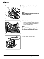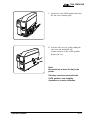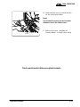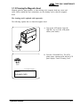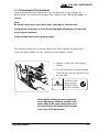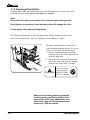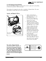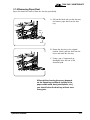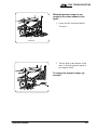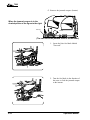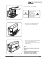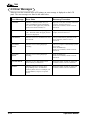
1
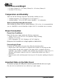
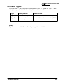
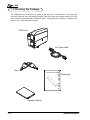
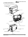
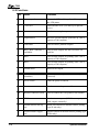
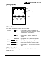
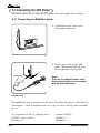
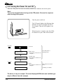
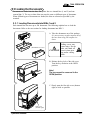
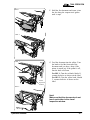
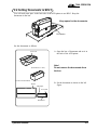
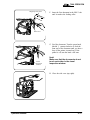
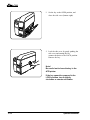
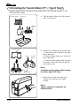
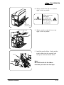
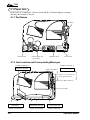
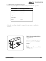
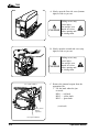
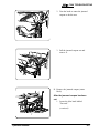
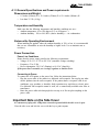
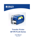
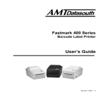
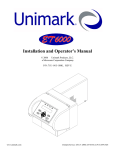
7200
ATB Printer
User's Guide
Part No. 111017 Rev. D
Table of
7200
Contents...
Introduction.............................................................. i
1. Before Using the ATB Printer ......................... 1-1
1.1 Checking the Package ....................................................... 1-2
1.2 Names and Functions ........................................................ 1-3
2. Operation.......................................................... 2-1
2.1 Connecting the ATB Printer .............................................. 2-2
2.2 Turning the Power On and Off .......................................... 2-4
2.3 Loading the Documents .................................................... 2-5
2.4 Setting Documents in BIN 3 ............................................. 2-9
2.5 Loading Documents into the Inserter .............................. 2-13
2.6 Installing the Transfer Ribbon (TT Only) ....................... 2-14
2.7 Changing Transfer Ribbons (TT Only) ........................... 2-18
3. Daily Maintenance ........................................... 3-1
3.1 Cleaning the ATB Printer .................................................. 3-2
3.1.1 Cleaning the Printer Surface ................................. 3-2
3.1.2 Cleaning the Magnetic Head................................. 3-3
3.1.3 Cleaning the Thermal Head .................................. 3-5
3.1.4 Cleaning a Platen Roller ....................................... 3-6
3.1.5 Cleaning a Carrier Roller ...................................... 3-7
3.1.6 Removing Paper Dust ........................................... 3-9
4. Troubleshooting .............................................. 4-1
4.1 Paper Jam .......................................................................... 4-2
4.2 Error Messages ................................................................ 4-12
Appendix 1: Specifications ........................................ A-1
Appendix 2: Consumables ......................................... A-5
Operation Manual
7200
(Page is intentionally blank)
Operation Manual
7200 INTRODUCTION
NOTICE
This equipment has been tested and found to comply with the limits for a Class A digital device,
pursuant to Part 15 of the FCC Rules. These limits are designed to provide reasonable protection
against harmful interference when the equipment is operated in a commercial environment.
This equipment generates, uses and can radiate radio frequency energy and, if not installed and
used in accordance with the instruction manual, may cause harmful interference to radio
communications. Operation of this equipment in a residential area is likely to cause harmful
interference in which case the user will be required to correct the interference at his own expense.
FCC WARNING
Changes or modifications not expressly approved by the party responsible for compliance could
void the user's authority to operate the equipment.
Operation Manual
i
7200
Product Safety
This manual uses a variety of terms and symbols to ensure the safe operation of the product,
help prevent hazards to yourself and others, and help prevent property damage. The
following
describes terms, symbols, and meanings used in this manual. Before reading this manual,
please familiarize yourself with the terms and symbols below.
Terms
WARNING
Ignoring this cautionary note and handling the product
improperly may result in death or serious injury.
CAUTION
Ignoring this warning and handling the product improperly
may result in injury or physical property damage.
Symbols
The triangle indicates the presence of danger. Specific details
of the danger are described in the triangle. (The symbol on the
right indicates danger of electric shock.)
This symbol indicates a prohibited action. Specific details of
the prohibition are described in or near the symbol. (The
symbol on the right indicates the item should not be
disassembled.)
This symbol indicates a mandatory action. Specific details of
the action are described in the symbol. (The symbol on the
right indicates that the power cable must be unplugged.)
ii
Operation Manual
7200 INTRODUCTION
Safety Considerations
READ THIS PAGE BEFORE INSTALLING OR USING THIS PRODUCT!
WARNING
n
Do not remove the cover or attempt any repairs on this product. There is risk
of electric shock.
n
Do not place heavy materials on the power cable. Do not bend or twist the power cable.
The cable may get damaged, causing fire or electric shock.
n
Do not use damaged cables or broken connector or power plugs. There is risk
of fire or electric shock.
n
Use only power voltages specified for this product. Improper voltages create a risk of
fire or electric shock.
n
Securely plug the power cable into a power receptacle. Metal objects touching the
power plug may cause fire, electric shock, or equipment malfunction.
n
Hold the plug when unplugging the power cable. Do not pull on the power cable itself,
or the cable may become damaged and cause fire or electric shock.
n
Be careful not to drop anything into any opening of the product. Never push anything
into the openings. There is risk of fire or electric shock.
n
In the event of any abnormality (such as smoke or odors), unplug the power
cable immediately. There is risk of fire or electric shock.
n
Do not install the product where water splashes are likely or in areas of high humidity.
There is risk of fire or electric shock.
n
Do not place drink or liquid containers or small metal objects on the product. These
items may cause fire or electric shock if they spill or fall inside. Immediately unplug
the power cable if liquids or metal objects are spilled on the product.
CAUTION
n
Do not use isopropyl alcohol around open flames or heat sources. Alcohol is highly
flammable and creates a risk of fire or explosion.
n
Be careful when opening or closing covers. Do not take your hands off covers when opening
or closing them. Falling covers may cause injury.
n
Be careful when opening, closing, or moving covers. Take care not to hit your face, head, or
hands with the open cover. You may be injured.
n
Do not block the air ventilation holes of the product. Blocking the vents accumulates heat
inside the cabinet and can lead to product failure, heat, or fire damage.
n
Do not install the product on an unstable or inclined surface. The product may fall and cause
damage or injury.
Operation Manual
iii
7200
Caution Label
This product comes with a caution label attached as described below.
Caution Label
CAUTION
Falling covers may
cause injury.
Do not take your
hands off covers
when opening and/
or closing them.
Operating Environment
Location
• Do not place the product in direct sunlight or near heating sources such as stoves or
heaters.
• Do not place the product in a dusty or humid environment.
• Do not place the product under strong shock or vibration.
• Do not place the product in a strong magnetic or radio field, or near a television set or
radio.
• Make sure that the vents are not blocked. Make sure that the installation location is well
ventilated and that air can freely circulate around the product.
• Do not place the product where contact with chemicals is likely.
iv
Operation Manual
7200 INTRODUCTION
Back
9.8 in (250mm)
Right
Front
8.3 in
(210mm)
9.8 in (250mm)
9.8 in (250mm)
9.8 in (250mm)
Top
Right
Left
9.8 in (250mm)
8.3 in
(210mm)
15 in (380mm)
Left
21.6 in (550mm)
5.9 in (150mm)
Space Required
9.8 in (250mm)
inches (millimeters)
Operation Manual
v
7200
Dimensions and Weight
• 8.3 inches (210mm) W x 21.6 inches (550mm) D x 15.0 inches (380mm) H
• Less than 35.3 lb. (16 kg )
Temperature and Humidity
Make sure that the following temperature and humidity conditions are met :
• Ambient temperature: 41 to 104 degrees F (5 to 40 degrees C)
• Ambient humidity: 20% to 90% RH (relative humidity) — no condensation.
Notes on the Operating Environment
When installing the product where the ambient humidity is 30% or less, it is recommended that
you use a humidifier to raise the humidity to higher levels. Use an antistatic mat as necessary.
Power Connection
Power Line Conditions
Ensure that the power supply satisfies the following requirements:
• Voltage: 85 to 132 or 170 to 265 VAC (automatic voltage switching)
• Frequency: 47 to 63 Hz
• Power consumption: 250 VAC (Printing) or 80 VAC (Stand by)
If the power line is unstable, use a voltage regulator or similar device.
Connecting to Power
To connect the ATB printer to the power line, follow the instructions below:
• Plug the power cable of the printer in a dedicated wall receptacle. Do not plug any other
electric products into the same receptacle. If the printer shares a receptacle with an air
conditioner, copy machine, or shredder, faulty operation may result due to electric noise. If a
dedicated wall receptacle cannot be used, use a commercially-available noise filter or
transformer.
• Route the power cable such that people do not step on it. Do not place anything on the power
cable.
Important Note on the Side Cover
As a measure of safety, this ATB printer cannot be operated while the side cover is open.
Close the side cover and lock the cover with the key to print coupons.
vi
Operation Manual
7200 INTRODUCTION
Available Types
The Sigma Data — 7200 ATB printer is classified into 2 types, i.e., Type B and Type D. Refer
to the printer types listed below when reading this manual.
Type
Printing Method
Number of Bins
Type B
Direct thermal only
Two internal bins and one external bin (BIN 3)
Type D
Direct thermal or
thermal transfer
Two internal bins and one external bin (BIN 3)
Note:
Type B cannot be used for Thermal Transfer printing with a transfer ribbon.
Operation Manual
vii
7200
NOTES
viii
(page is intentionally blank)
Operation Manual
7200 BEFORE USING THE S7200
1.
Before Using the ATB Printer
Operation Manual
1-1
7200
1.1 Checking the Package
The ATB printer and accessories are packed in the same box. Carefully remove the printer and
accessories from the box and packing materials, then check that the package contains all of the
items needed for operation that are pictured below. The package also contains a warranty card
and may have other information sheets.
ATB Printer
AC Power Cable
Keys
Cleaning Kit
Operation Manual
1-2
Operation Manual
7200 BEFORE USING THE S7200
1.2 Names and Functions
This section explains the names and functions of each part.
1.2.1 Names of Parts
A — Operator panel
B — Cover lock
E — Feed knobs
D — Output stacker
C — Inserter
F — BIN 1,
BIN 2, and
BIN 3 load
knobs
G — BIN 1
O — Thermal
transfer take-up reel
H — BIN 2
N — BIN 3
I — Thermal print head
P — Thermal transfer supply reel
J — Interface connector
(Downline)
M — Interface connector
(Host)
HOST DOWNLINE
K — Power switch
L — Power connector
Operation Manual
1-3
7200
1.2.2 Functions
1-4
No.
Names
Functions
A
Operator panel
Houses the LEDs and keypad needed to operate
the ATB printer.
B
Cover lock
Locks the side cover. (Use the key to open the
cover.)
C
Inserter
Used to insert single coupons (one at a time).
D
Output stacker
Receives ejected coupons, print-side up. (Has a
capacity of 100 coupons.)
E
Feed knobs
Used to remove jammed coupons.
F
BIN 1, BIN 2, and BIN 3
load knobs
Used to load coupons into the feed rollers for
each bin.
G
BIN 1
Used to hold coupons for printing. (BIN 1 has a
capacity of 500 coupons.)
H
BIN 2
Used to hold coupons for printing. (BIN 2 has a
capacity of 500 coupons.)
I
Thermal head
Prints on the coupon.
J
Interface connector
(downline)
Used to connect the printer to a downline printer
(reserved).
K
Power switch
Turns the power on and off.
L
Power connector
Used to connect the power cable.
M
Interface connector (Host)
Used to connect the ATB printer to the terminal.
N
BIN 3
Used to insert coupons. (BIN 3 has a capacity of
1000 coupons externally.)
O
Thermal transfer take-up
reel
Holds used ribbon after thermal transfer printing
(type D unit only).
P
Thermal transfer supply
reel
Supplies ribbon for thermal transfer printing (type
D unit only).
Operation Manual
7200 BEFORE USING THE S7200
1.2.3 Operator Panel
Operator Panel Layout
ONLINE
ERROR
DATA
MODE
LEDs
LCD
16 columns by 2 rows
ONLINE
ENTER
RESET
QUIT
EJECT
TEST
SET UP
CLEANING
ç
è
ê
é
Keys
LED Functions
LEDs indicate printer status by turning on, turning off, or blinking.
ONLINE
ON
— The ATB printer is online. The ATB printer can
receive and print data from the terminal. The printer is
set online when the power is turned on.
OFF
— The ATB printer is offline (i.e., Setup and Test
available).
Blinking — An ATB printer error or improper Host connection.
DATA
ON
ERROR
ON
MODE
ON
— The ATB printer is sending or receiving data to or from
the terminal, or is printing coupons.
— An error or jam has occurred. (The buzzer sounds.)
— The ATB printer is in TEST, SETUP, or CLEANING
mode.
LCD Panel Functions
The LCD panel displays the operating status or setup values for the ATB printer in 16
columns and 2 rows.
Operation Manual
1-5
7200
Key Functions
Each key has two different functions for different operating modes.
Function indicated at the top
Enabled in ONLINE or OFFLINE mode.
Function indicated at the bottom
Enabled in TEST, SETUP, or CLEANING modes.
Functions
ONLINE
ENTER
key
ONLINE
Cycles the ATB printer between ONLINE (ticketing enable) and
OFFLINE (local) mode. If the ATB printer is online, pressing
this switch sets it offline. If the ATB printer is offline, pressing
this switch sets it online.
ENTER
This switch executes the menu item displayed on the LCD panel
or registers the setup settings. Pressing this key changes and
stores the setup values for each item of the setup menu.
RESET
QUIT
key
RESET
In the event of an error, pressing this key stops the buzzer and
releases the error.
QUIT
Pressing this key ends the menu item displayed on the LCD
panel.
EJECT
é
key
EJECT
Pressing this key ejects any coupons inside.
é
Pressing this key selects the menu item or the setup value on the
LCD panel. Automatic repeat when held down.
1-6
Operation Manual
7200 BEFORE USING THE S7200
TEST
ç
key
TEST
In OFFLINE (local) mode, pressing this key sets the ATB printer
to TEST mode (maintenance mode).
ç
Pressing this key moves the cursor on the LCD panel to the left.
Automatic repeat when held down.
SET UP
è
key
SET UP
In OFFLINE (local) mode, pressing this key sets the ATB printer
to SETUP mode (maintenance mode).
è
Pressing this key moves the cursor on the LCD panel to the right.
Automatic repeat when held down.
CLEANING
ê
key
CLEANING
In OFFLINE (local) mode, pressing this key sets the ATB printer
to CLEANING mode.
ê
Pressing this key selects the menu item or the setup value on the
LCD panel. Automatic repeat when held down.
Operation Manual
1-7
7200
NOTES
1-8
(page is intentionally blank)
Operation Manual
7200 OPERATION
2.
Operation
Operation Manual
2-1
7200
2.1 Connecting the ATB Printer
This section explains how to connect the ATB printer to the power supply and the terminal.
2.1.1 Connecting to a Wall Receptacle
A. Check that the power switch on the
ATB printer is turned off.
B. Plug the power cable into the ATB
printer. Then, plug the other end of the
power cable into a wall receptacle.
Ferrite Core
Note!
Only use the supplied power cable.
Ensure that the power cord complies
with all local ordinances.
IMPORTANT...
The Ferrite Core must be attached to the AC Power Cord before the printer is connected to the
wall receptacle. Failure to attach the Ferrite Core to the AC Power Cord may cause non-compliance to:
FCC Regulations for Class A computing device
EN55022-1 Class A Limits
EN61000-3-2
2-2
Canadian ICES-003
EN50082-1
EN61000-3-3
Operation Manual
7200 OPERATION
2.1.2 Connecting the Terminal
Before connecting the printer to a terminal, do the following:
A. Ensure that both the ATB printer and the
terminal are turned off.
B. Attach the communications cable to the
RS-232 port located on the back of the
ATB printer, labeled “HOST.” Then
connect the cable to the terminal.
HOST
Operation Manual
2-3
7200
2.2 Turning the Power On and Off
After the ATB printer has been successfully installed and connected, turn on the power.
Note!
Turn on the terminal before turning on the ATB printer. Reverse the sequence
when turning off the power.
Turn the power switch on.
The LCD panel displays the following three
indicators in turn for specified intervals (a
few seconds). Then, the ATB printer is set
online.
When the power is turned on, the four LEDs
are turned on as part of the self test routine.
ONLINE
LCD Test
(OFF)
ONLINE
S7200/PC94.03.08
ROM Version
(The display on the left is an
example.)
S7200/08.30
Mecha.Type: D
Available Type
(The display on the left is an
example.)
The ATB printer is
checking itself.
CHECK-IN
(ON)
or
TICKETING
Modes
(The display on the left is an
example.)
This indicates the online
status.
(Ticketing is enabled.)
The above is only an example. The actual displayed ROM value and available type
may be different from this example.
2-4
Operation Manual
7200 OPERATION
2.3 Loading the Documents
Documents are loaded into the bins. The printer has two internal bins (1 and 2) and one
external bin (3). The two or three bins can store the same or different types of documents.
When different types of documents are loaded, the bins are selected as specified by the
terminal.
2.3.1 Loading Documents into BINs 1 and 2
Each internal bin can store up to 500 documents. The following explains how to load the
documents. Refer to the next section for loading documents into BIN 3.
A. Take the documents out of the package.
It is not necessary to take coupons out of
the box when using 500 coupon size
boxes.
(Documents in a box)
CAUTION
Falling covers may
cause injury. Do not
take your hands off
covers when opening and/or closing
them.
B. Release the key lock of the side cover.
Turn the key clockwise to the OPEN
position.
Note!
The key cannot be removed in the
OPEN position.
C. Slowly open the first side cover (bottom
right) as wide as possible.
Side cover
(bottom right)
Operation Manual
2-5
7200
Side cover (top right)
D. Slowly open the second side cover (top
right) as wide as possible.
E. Load the documents into the bin, with the
magstripe facing up and the front end on
the right. Load the box in the same manner,
with the magstripe facing up and the front
end on the right. There are two bins (BIN 1
and 2). Each bin can store up to 500
documents.
Magstripe
(When loading a box)
Document Orientation
NOTE!
DO NOT load more than 500 coupons in
BINS 1 and 2 or print jamming may
occur!
Magstripe
Note!
Neatly align the documents in the bins
with the magstripe to the inside of the
machine.
BIN 2
2-6
Front end
BIN 1
Operation Manual
7200 OPERATION
BIN 1
F. Hold the first document and insert it into
the slot along the coupon travel guides
until it stops.
BIN 2
BIN 1
Visual
inspection
window
G. Feed the document into the rollers. Turn
the knob to feed the front end of the
document until you hear a beep (if the
printer is turned on). If the printer is off,
turn the knob a full turn.
For BIN 1: Turn the red knob, labeled 1,
counter-clockwise as shown on the label.
For BIN 2: Turn the yellow knob, labeled
2, counter-clockwise as shown on the
label.
BIN 2
Note!
Make sure that the documents do not
touch each other in the visual
inspection window.
Operation Manual
2-7
7200
H. Close the side cover (top right).
I. Set the key to the OPEN position, and
close the side cover (bottom right).
J. Lock the side cover by gently pushing the
side cover and turning the key
counter-clockwise to the LOCK position.
Remove the key.
Note!
Be careful not to leave the key in the
ATB printer.
If the key cannot be removed in the
LOCK position, turn it slightly clockwise
or counter-clockwise.
2-8
Operation Manual
7200 OPERATION
2.4 Setting Documents in BIN 3
You will need some space in the back side of the ATB printer to use BIN 3. Keep the
documents in the box.
Keep space for the documents.
Documents
Set the documents as follows:
A. Open the box of documents and set it in
the back of the ATB printer.
Front end
(Documents in a box)
Note!
Do not remove the documents from
the box.
Printer
B. Set the documents as shown in the left
figure.
Location of documents
Magstripe
Front end
Documents
Operation Manual
2-9
7200
C. Release the key lock for the side cover.
Turn the key clockwise to the OPEN position.
Note!
The key cannot be removed in the
OPEN position.
Falling covers may
cause injury.
Do not take your
CAUTION hands off covers
when opening and/
or closing them.
D. Slowly open the first side cover (bottom
right) as wide as possible.
Side cover
(bottom right)
Side cover (top right)
2-10
E. Slowly open the second side cover (top
right) as wide as possible.
Operation Manual
7200 OPERATION
Magstripe face down
F. Insert the first document in the BIN 3 slot
until it touches the feeding roller.
BIN 3 slot
G. Feed the document. Turn the green knob,
labeled 3, counter-clockwise to feed the
front end of the document until you hear a
beep (if the printer is turned on). If the
printer is off, turn the knob a full turn.
Visual
inspection
window
Note!
Make sure that the documents do not
touch each other in the visual
inspection window.
H. Close the side cover (top right).
Operation Manual
2-11
7200
I. Set the key to the OPEN position, and
close the side cover (bottom right).
J. Lock the side cover by gently pushing the
side cover and turning the key
counter-clockwise to the LOCK position.
Remove the key.
Note!
Be careful not to leave the key in the
ATB printer.
If the key cannot be removed in the
LOCK position, turn it slightly
clockwise or counter-clockwise.
2-12
Operation Manual
7200 OPERATION
2.5 Loading Documents into the Inserter
While the ATB printer is on, you can use the inserter to read and/or print a document. Note
that only one document can be inserted at one time.
With the printer turned on, insert a
document into the inserter slot until you
hear a beep. The ATB printer then draws the
document in for printing.
Note!
Insert only one document at a time.
Do not insert the next document
before the previous document is
ejected. Otherwise, a double-feed or
paper jam occurs.
Document
Print face-up
Magstripe
face-down
Note!
Do not insert the coupon portion of the document (only)
or a paper jam can occur. To clear a paper jam, see "Removing the Jammed Coupon" in Section 4.1 and, perform the jam
removing procedure for the inserter.
Coupon
Operation Manual
2-13
7200
2.6 Installing the Transfer Ribbon (TT — Type D Only)
Install the transfer ribbon according to the procedure below. The following operation is only
used for thermal transfer.
Transfer ribbon
A.1 Take the transfer ribbon out of the bag and
remove the protector.
Protector
Ribbon
loader
Transfer ribbon
Guide
Transfer
ribbon
Ribbon loader
B. Install the new ribbon on the ribbon loader:
a) Place the full roll of ribbon on the right
side of the loader.
b) Place the empty take-up core on the left
side of the loader.
c) Pass the transfer ribbon (film) along the
two guides on the roller, from the full roll
to the take-up core.
Note!
Install the transfer ribbon while keeping
the ribbon tight, NOT slack.
C. Release the key lock of the side cover.
Turn the key clockwise to the OPEN
position.
Note!
The key cannot be removed in the
OPEN position.
2-14
Operation Manual
7200 OPERATION
D. Slowly open the first side cover (bottom
right) as wide as possible.
Falling covers may
cause injury.
Do not take your
CAUTION hands off covers
when opening and/
or closing them.
Side cover
(bottom right)
Side cover (top right)
Pivots
E. Slowly open the second side cover (top
right) as wide as possible.
F. Install the transfer ribbon. Gently push the
transfer ribbon into the receptacle until
both pivots click and hold the ribbon.
Note!
Be careful not to let the ribbon
insertion port catch the lead tape.
Operation Manual
2-15
7200
G. Remove the ribbon loader. Squeeze the
lock with your fingers to remove the
loader.
Lock
Note!
Make certain that both ribbon cores are
clicked on the pivots.
Transfer ribbon winding direction
H. Turn the ribbon take-up core in the
direction of the arrow until the ink portion
of the transfer ribbon is seen. Then, turn it
at least 3 additional times.
Note!
Be careful of which direction you turn
the ribbon core. Only turn the core in
the direction indicated by the arrow!
I. Close the side cover (top right).
2-16
Operation Manual
7200 OPERATION
J. Set the key to the OPEN position and close
the side cover (bottom right).
K. Lock the side cover by gently pushing the
side cover and turning the key
counter-clockwise to the LOCK position.
Remove the key.
Note!
Be careful not to leave the key in the
printer.
If the key cannot be removed in the
LOCK position, turn it slightly
clockwise or counter-clockwise.
Operation Manual
2-17
7200
2.7 Changing Transfer Ribbons (TT — Type D Only)
When the transfer ribbon needs replacement, the LCD panel displays a message.
LCD Panel Display
The following operation is only for
thermal transfer.
WARNING:
END OF RIBBON
Replace the transfer ribbon following the steps below:
A. Release the key lock of the side cover.
Turn the key clockwise to the OPEN
position.
Note!
The key cannot be removed in the
OPEN position.
B. Slowly open the first side cover (bottom
right) as wide as possible.
CAUTION
Side cover
(bottom right)
Side cover (top right)
2-18
Falling covers may
cause injury.
Do not take your
hands off covers
when opening and/
or closing them.
C. Slowly open the second side cover (top
right) as wide as possible.
Operation Manual
7200 OPERATION
D. Pinch both blue pivots to unlock and take
out the used transfer ribbon.
Note!
It is normal for some unused transfer
ribbon to be on the ribbon core.
Pivots
E. Refer to the section, “Installing the
Transfer Ribbon,” to install a new ribbon.
Treat used transfer ribbons as plastic waste.
Operation Manual
2-19
7200
NOTES
2-20
(page is intentionally blank)
Operation Manual
7200 DAILY MAINTENANCE
3.
Daily Maintenance
Operation Manual
3-1
7200
3.1 Cleaning the ATB Printer
This section explains the ATB printer components that need regular cleaning.
Notes on Cleaning:
Turn the power off and unplug the power cable before starting any cleaning
procedure except when using the cleaning card!
Only use water or neutral detergents, or isopropyl alcohol as specified. Never use
harsh cleaning chemicals!
3.1.1 Cleaning the Printer Surface
Use a cloth moistened with water or a neutral detergent to wipe the ATB printer surface.
Squeeze or wring the cloth to remove excess water and leave the cloth damp rather than
dripping wet. Use a soft, dry cloth for the final wiping. Make certain the ATB printer surface
is completely dry!
3-2
Operation Manual
7200 DAILY MAINTENANCE
3.1.2 Cleaning the Magnetic Head
Magnetic particles, paper particles, or dust sticking to the magnetic head may cause read
errors. Before starting the day's transactions, use the cleaning card to clean the magnetic
head.
The cleaning card is optional (sold separately).
The following explains how to clean the magnetic head.
A. Turn on the ATB printer. Press the
ONLINE key to set the ATB printer
offline (local mode).
ONLINE
ENTER
B. Press the CLEANING key. The ATB
printer enters cleaning mode and the LCD
panel displays "Insert Cleaning Card."
CLEANING
•
«
LCD Panel Display
INSERT
CLEANING CARD
Operation Manual
3-3
7200
C. Insert the cleaning card.
•
Insert the cleaning card with the
instruction label on the card facing
upward.
•
The LCD panel displays "Maghead
Cleaning." while the ATB printer
cleans the magnetic head.
•
At the end of cleaning, the cleaning
card is automatically ejected into the
output stacker.
Output stacker
Cleaning card
Repeat the cleaning procedure several times as necessary.
3-4
Operation Manual
7200 DAILY MAINTENANCE
3.1.3 Cleaning the Thermal Head
Clean the thermal head when replenishing a bin with documents or when changing the
transfer ribbon. Use a cotton swab moistened with isopropyl alcohol. Do not use thinner or
benzene.
Note!
Be careful not to injure your hands when cleaning the thermal head.
Using thinner or benzene to clean the thermal head will damage the head and
may void your warranty.
A dirty thermal head lowers printing clarity.
The following explains how to clean the thermal head. Before cleaning the thermal head,
remove the transfer ribbon. (See the "Changing Transfer Ribbons" section)
1. Moisten a cotton swab with isopropyl
alcohol.
2. Use the cotton swab to clean the thermal
head. Rub the swab back and forth across
the print head.
Avoid fire when
using isopropyl
CAUTION alcohol to reduce
the risk of burning.
Although the cleaning frequency depends
on the operating conditions (quality of the
paper media used, dusty atmosphere, etc.),
you should clean the thermal head at least
once every 5,000 documents.
Operation Manual
3-5
7200
3.1.4 Cleaning a Platen Roller
Clean the platen roller when replenishing a bin with documents. Use a cotton swab moistened with isopropyl alcohol. Do not use thinner or benzene.
Note!
Be careful not to injure your hands if you clean the platen roller yourself.
Using thinner or benzene to clean the platen roller will damage the roller.
A dirty platen roller lowers printing clarity.
The following explains how to clean the platen roller. Before cleaning the platen roller,
remove the transfer ribbon. (See the "Changing Transfer Ribbons" section.)
The platen roller should be cleaned with a
swab containing isopropyl alcohol. The platen
roller is located below the thermal head.
1. Rub the cleaning swab back and forth
across the top of the roller located directly
under the print head.
2. Rotate the blue feed knob (located to the
left of this roller) and repeat the cleaning
motion so the entire roller is cleaned.
Avoid fire when
using isopropyl
CAUTION alcohol to reduce
the risk of burning.
Although the cleaning frequency depends
on the operating conditions (quality of the
paper media used, dusty atmosphere, etc.),
you should clean the thermal head at least
once every 5,000 documents.
3-6
Operation Manual
7200 DAILY MAINTENANCE
3.1.5 Cleaning a Carrier Roller
Paper dust and other dirt clinging to a carrier roller can cause a paper jam or poor printing
(ex. data can be printed at a slant on the paper).
The procedure for cleaning the carrier roller is explained as illustrated below. The carrier
roller should be cleaned while the side cover remains open.
Inserter and Magnetic Blocks
Cleaning sheet
Blue knob labeled
FORWARD
Leading edge of
the cleaning sheet
The carrier rollers should be
cleaned every 5000 coupons or if
the printer performance degrades
(jams, print quality, roller slipping,
etc.). The long, thin cleaning sheet
is used for cleaning carrier rollers,
(not the card with the printed label
which is used to clean the magnetic
heads).
Operation Manual
1. Apply a small amount of
isopropyl alcohol to the long,
thin cleaning sheet.
2. Insert the long cleaning sheet
into the insert slot until it rests
against the feed rollers.
3. Turn the blue knob (labeled
"Forward") clockwise to pull the
cleaning sheet into the document
path until about 1.2 to 1.5 inches
(30mm to 40mm) of the sheet
remains exposed in the front.
4. Hold the exposed part of the
cleaning sheet firmly with one
hand while again turning the blue
knob clockwise. Turn the knob
several turns to clean the feed
rollers thoroughly.
5. To remove the sheet, turn the
blue knob counter-clockwise
while gently pulling the exposed
sheet until the sheet completely
exits the front of the printer.
Avoid fire when
using isopropyl
CAUTION alcohol to avoid the
risk of burning.
3-7
7200
Bin and Cutter Blocks
Upper knob — for
cleaning stock bin
roller
Lower knob —
for cleaning
cutter block
roller
Head position of the
cleaning sheet
The stock bin and burster rollers
should be cleaned every 5000
documents or if printer performance
degrades. The long, thin cleaning
sheet is used for cleaning rollers, (not
the card with the printed label which
is used to clean the magnetic heads).
Avoid fire when
using isopropyl
CAUTION alcohol to avoid the
risk of burning.
3-8
1. Uniformly apply a small amount of
isopropyl alcohol to the long, thin
cleaning sheet.
2. Insert the long cleaning sheet into the BIN
1 insert slot until it rests against the feed
rollers.
3. Turn the red knob (labeled "1") counterclockwise to pull the cleaning sheet into
the document path until a resistance is
felt.
4. Turn the blue knob (labeled "Forward")
counter-clockwise until about 1.2 to 1.5
inches (30mm to 40mm) of the sheet
remains exposed in BIN 1 as shown in the
illustration.
5. To clean the BIN 1 feed rollers, hold the
blue knob firmly while rotating the red
BIN 1 knob clockwise for several turns.
6. To clean the burst rollers, hold the
exposed cleaning sheet firmly with one
hand while turning the blue knob counterclockwise for several turns.
7. To remove the sheet, turn both the blue
knob and the red knob clockwise until the
sheet is returned to BIN 1.
To Clean BIN 2:
a) Repeat Steps 1 through 5, except, insert
the cleaning sheet into the BIN 2 slot and
turn the yellow knob (labeled "2") instead
of the red knob.
b) To remove the cleaning sheet, follow Step
7, except, use the yellow knob instead of
the red knob.
To Clean BIN 3:
a) Repeat Steps 1 through 5, except, insert
the cleaning sheet into the BIN 3 slot (on
the back of the printer) and turn the green
knob (labeled "3") instead of the red
knob.
b) To remove the cleaning sheet, follow Step
7, except, use the green knob instead of
the red knob.
Operation Manual
7200 DAILY MAINTENANCE
3.1.6 Removing Paper Dust
Paper dust should be removed from the dust tray periodically.
A. Pull out the knob, take out the dust tray,
and remove paper dust from the dust
tray.
Dust
tray
Knob
B. Return the dust tray to the original
position. Firmly push the knob into the
recess and insert the dust tray.
C. Using a can of compressed air,
thoroughly blow dust out of the
document path.
Although the cleaning frequency depends
on the operating conditions (quality of the
paper media used, dusty atmosphere, etc.),
you should clean the dust tray at least once
every year.
Operation Manual
3-9
7200
NOTES
3-10
(page is intentionally blank)
Operation Manual
7200 TROUBLESHOOTING
4.
Troubleshooting
Operation Manual
4-1
7200
9.1 Paper Jam
In the event of a coupon jam, a buzzer sounds and the LCD panel displays a message
indicating the location of the jam.
4.1.1 Part Names
Bin block
Inserter block
Printing block and
output stacker
Cutter block
Magnetic block
4.1.2 Jam Locations and Corresponding Messages
PAPER JAM:ZONE C
PAPER JAM:ZONE A
PRINTING BLOCK
STOCKER __
Paper jam in BIN 2
Either of 1, 2, or 3 is displayed on
the LCD panel shown above.
Paper jam in BIN 3 (Option)
Paper jam in BIN 1
INSERTER
PAPER JAM:ZONE B
4-2
MAGNETIC BLOCK
CUTTER BLOCK
PAPER JAM:ZONE B
PAPER JAM:ZONE A
Operation Manual
7200 TROUBLESHOOTING
4.1.3 Removing the jammed coupon
To remove the jammed coupon, check the location of the jam and follow the steps below.
Jam Position
Removing Procedures
Stocker (Bin) block
A, B, C‚ H, I, J
Cutter block
A, B, D, H, I, J
Magnetic block
A, E, I, J
Printing block
Output stacker
A, F, I, J
Inserter
A, G, I, J
• In the table above, Steps A through J correspond to the step numbers in the following
procedures.
Unlock the cover before starting
any procedure.
Release the key lock on the side cover.
Turn the key clockwise to the OPEN
position.
Note!
The key cannot be removed in the
OPEN position.
Operation Manual
4-3
7200
A. Slowly open the first side cover (bottom
right) as wide as you can.
Falling covers may
cause injury.
Do not take your
CAUTION hands off covers
when opening and/
or closing them.
B. Slowly open the second side cover (top
right) as wide as you can.
Falling covers may
cause injury.
Do not take your
CAUTION hands off covers
when opening and/
or closing them.
For a jam in BIN 1
C. Remove the jammed coupon from the
appropriate bin.
1. Use the knob where the jam
occurred:
BIN 1 — red knob
BIN 2 — yellow knob
BIN 3 — green knob
(continued)
For a jam in
BIN 3
(Option)
For a jam in BIN 2
4-4
Operation Manual
7200 TROUBLESHOOTING
2. Turn the knob to return the jammed
coupon to the bin area.
3. Pull the jammed coupon out and
remove it.
D. Remove the jammed coupon (cutter
block)
After the jammed coupon has been
cut:
1. Locate the blue knob labeled
"Forward."
(continued)
Feed knob
Operation Manual
4-5
7200
2. Turn the feed knob to feed the
jammed coupon to the magnetic
block. (Go to Step E to remove the
jammed coupon.)
Feed
knob
If the jammed coupon has NOT been
cut:
1. Use the knob for the appropriate bin
AND the feed knob.
2. Turn both knobs clockwise
simultaneously to return the jammed
coupon to the input slot.
(continued)
Feed knob
4-6
Operation Manual
7200 TROUBLESHOOTING
3. Pull the jammed coupon out of the
input slot and remove the damaged
coupon.
E. Remove the jammed coupon from the
magnetic block.
1. Insert your fingers into the hole on the
guide face, then lift and remove the
jammed coupon while rotating the
feed knob back and forth.
Side pressure
roller
Operation Manual
2. Take out the jammed document
while pulling down the side pressure
roller. (The document is lifted up
when the side pressure roller is
pulled down.)
4-7
7200
F. Remove the jammed coupon from
the printing block and output
stacker.
The method varies depending
on the location of the jammed
coupon.
When the jammed coupon is caught by
the rollers shaded in the figure to the
right:
Printing block and
output stacker block
1. Locate the blue feed knob for the
output stacker.
Feed knob
2. Turn the feed knob in the direction
of the arrow to feed the jammed
coupon to the output stacker.
4-8
Operation Manual
7200 TROUBLESHOOTING
When the jammed coupon is not
caught by the rollers shaded in the
figure:
1. Locate the blue feed knob labeled
"Forward."
Feed knob
2. Turn the knob in the direction of the
arrow to feed the jammed coupon to
the magnetic block.
To remove the jammed coupon, go
to step E.
Operation Manual
4-9
7200
G. Remove the jammed coupon. (Inserter)
When the jammed coupon is in the
shaded portion of the figure to the right:
Inserter
Blade
(The rear end of the jammed ticket is on the blade.)
1. Locate the blue feed knob labeled
"Forward."
Feed knob
2. Turn the feed knob in the direction of
the arrow to feed the jammed coupon
to the inserter.
4-10
Operation Manual
7200 TROUBLESHOOTING
H. Close the side cover (top right).
CAUTION
Falling covers may
cause injury.
Do not take your
hands off covers
when opening and/
or closing them.
I. Set the key to the OPEN position, and
close the side cover (bottom right).
J. Lock the side cover by gently pushing the
side cover and turning the key
counter-clockwise to the LOCK position.
Remove the key.
Note!
Be careful not to leave the key in the
printer.
If the key cannot be removed in the
LOCK position, turn it slightly
clockwise or counter-clockwise.
Operation Manual
4-11
7200
4.2 Error Messages
When an error has occurred in the ATB printer, an error message is displayed on the LCD
panel. The error messages are listed in the table below.
Error Message
Error State
Recovery Procedure
WARNING:
Indicates a relatively minor error, ex.
when consumption articles (documents,
etc.) has run short (paper-out), when the
operator has made a mistake, etc.
Open the cover, take necessary actions for
recovery, and close the cover.
If the error continues, contact a service
technician.
PAPER JAM:
Indicates an error caused by the paper
jam. The block where the paper jam has
occurred is displayed.
Open the cover, remove the jammed
coupon, and close the cover.
COM.ERROR:
Indicates an error in communication with
the terminal.
Verify communication parameters. If the
error continues, contact a service
technician.
ENCODING
ERROR:
Indicates an error during magstripe
encoding.
The error coupon is automatically ejected
and voided.
Press the RESET key.
If the error continues, contact a service
technician.
MAGNETIC
ERROR:
Indicates an error during magstripe
decoding.
Press the RESET key.
If the error continues, contact a service
technician.
SYSTEM ERROR:
Indicates an error that seldom occurs
under ordinary circumstances.
Power the printer off and on. If the error
continues, contact a service technician.
OTHERS:
Indicates other errors such as AEA
programming errors, etc.Indicates a
relatively minor error. For example, end
of expendables (coupons) or operator
errors.
Power the printer off and on. If the error
continues, contact a service technician.
4-12
Operation Manual
7200 TROUBLESHOOTING
Error Message
Error State
Recovery Procedure
OUT OF
REQUESTED PAPER
The requested document has ended.
Install the documents.
ENCODING ERROR
REMOVE VOID DOC.
Encoding could not be executed normally.
Remove the void coupon.
MULTIPLE ENCODING
ERROR
Encoding error has occurred twice
continuously.
Remove the void coupon and clean
the magnetic head. Verify that the
coupon is properly inserted.
CHECK-IN
IN PROGRESS
The interface has an error.
(During the Check-In.)
Wait for the Check-In to end.
TICKETING
IN PROGRESS
The interface has an error.
(During the ticketing.)
Wait for the Ticketing to end.
WARNING:
END OF RIBBON
Ribbon ends (when TT is set)
Install a new transfer ribbon.
(Refer to "Changing Transfer
Ribbons".)
WARNING:
DETACHED RIBBON
No transfer ribbon (when TT is set)
Install a transfer ribbon.
(Refer to "Installing the Transfer
Ribbon".)
WARNING:
ATTACHED RIBBON
Ribbon is installed when the printer is in
direct thermal mode.
Remove the transfer ribbon.
WARNING:
STACKER FULL
The output stacker is full.
Remove the document from the
output stacker.
WARNING:
COVER OPENED
The cover is open.
Close and lock the cover.
WARNING:
PAPER OUT 1 2 3
Documents have run out (in this case, only
the related bin is displayed).
Load documents.
TAKE YOUR
DOCUMENT
Not an error.
Take the coupon.
PAPER JAM:ZONE A
STOCKER 1
Paper jam in BIN 1.
Remove the jammed coupon.
(Refer to "Paper Jam".)
PAPER JAM:ZONE A
STOCKER 2
Paper jam in BIN 2.
PAPER JAM:ZONE A
STOCKER 3
Paper jam in the slot of BIN 3.
PAPER JAM:ZONE A
CUTTER BLOCK
Paper jam in the cutter block.
PAPER JAM:ZONE B
MAGNETIC BLOCK
Paper jam in the magnetic block.
PAPER JAM:ZONE C
PRINTING BLOCK
Paper jam in the printing block.
PAPER JAM:ZONE B
INSERTER
Paper jam in the front inserter.
Operation Manual
4-13
7200
The following error messages are reference data. They concern a service engineer.
4-14
Error Message
Error State
Recovery Procedure
ILLOGICAL
COMMAND
The interface has an error.
(An illogical command has been received.)
Contact a service technician.
INCORRECT FIELD
The interface has an error.
(An incorrect element has been received.)
OUT OF
SEQUENCE
The interface has an error.
(The sequence of the inserted document is
incorrect.)
NO PECTAB
AVAILABLE
The interface has an error.
(No PECTAB is available.)
ERRONEOUS
ELEMENT**
The interface has an error.
(The PECTAB element error has occurred.)
ERRONEOUS
CLF CODE
The interface has an error.
(The PECTAB CLF error has occurred.)
PECTAB
EXCEEDS 4K
The interface has an error.
(The PECTAB exceeds 4K bytes.)
MEMORY OVERFLOW
The interface has an error.
(Memory has overflowed.)
DOCUMENT UNKNOWN
TO PRINTER
The interface has an error.
(The specified document type has not been
defined by the ATB printer.)
LOGO
LOAD ERROR
The interface has an error.
(The logo load text has an error.)
CANNOT MODIFY
LOGO FILE ON ROM
The interface has an error.
(An attempt was made to update the logo
loaded on the ROM.)
CANNOT DELETE
LOGO FILE ON ROM
The interface has an error.
(An attempt was made to delete the logo
loaded on the ROM.)
TEMPLATE
LOAD ERROR
The interface has an error.
(The template text has an error.)
CANNOT MODIFY
TEMPLEATE ON ROM
The interface has an error.
(An attempt was made to update the
template on the ROM.)
CANNOT DELETE
TEMPLEATE ON ROM
The interface has an error.
(An attempt was made to delete the
template on the ROM.)
LOGO(OBJECT)
NOT FOUND
The ineterface has an error.
(The specified logo was not found in the
template.)
ILLEGAL
COUPON NUMBER
The interface has an error.
(Documents are not arranged in descending
order up to 01.)
SYSTEM ERROR:
PRINT HEAD
An error has occurred in the print head.
SYSTEM ERROR:
RIBBON REWINDING
An error has occurred during ribbon
rewinding.
Operation Manual
7200 TROUBLESHOOTING
Error Message
Error State
Recovery Procedure
SYSTEM ERROR:
PRINT POSITION
An error has occurred during the print head
positioning.
Contact a service technician.
SYSTEM ERROR:
FUSE
A fault was detected in the fuse.
SYSTEM ERROR:
SERVOMOTOR
The servo motor is overloaded.
COM.ERROR:
PARITY
The RS232C interface has an error.
(An error was detected in the
communication parity.)
COM.ERROR:
PROTOCOL = **
The RS232C interface has an error.
An error was detected in the communication
protocol. (Ex. STX, ETX, LRC, time-out,
etc.)
COM.ERROR:
FRAME
The RS232C interface has an error.
An error was detected in the communication
framing.
COM.ERROR:
OVER RUN
The RS232C interface has an error.
Communication overrun error
COM.ERROR:
BLOCK TOO LONG
The RS232C interface has an error.
Too-long block was received.
MAGNETIC ERROR:
XXX XXX XXX XXX
A magnetic error was detected in the track,
block, etc.
SYSTEM ERROR:
PARAMETER FAULT
The incorrect setup parameter was
specified.
SYSTEM ERROR:
EXP.ROM FAULT
An error was detected in the extension
memory.
SYSTEM ERROR:
PECTAB FAULT
A fault was detected in PECTAB.
SYSTEM ERROR:
BATTERY LOW
The voltage of the backup battery is low.
SYSTEM ERROR:
MCU ERRCODE = **
System error
SYSTEM ERROR:
SCU ERRCODE = **
System error
SCN ERROR:
MAG.NOT FOUND
Non-existent error
SCN ERROR:
NOT READABLE
SCN reading errors occurred twice
successively.
SCN ERROR:
NOT FOUND
When a command for asking SCN was
received, SCN reading error occurred.
SCN ERROR:
BIN NOT FOUND
Setting error for SCN
SCN READING ERR
REMOVE VOID DOC.
SCN reading error
Operation Manual
4-15
7200
NOTES
4-16
(page is intentionally blank)
Operation Manual
7200 APPENDIX
Appendix 1: Specifications
A.1.1 Document Carrier Structure
BIN 2
BIN 1
Output stacker
BIN 3
Inserter
Cutter block
Printing block
Magnetic block
Document Carrier Structure
Operation Manual
APPENDIX-1
7200
A.1.2 Covers
Open (swing down) the bottom right side cover first, then open (swing up) the top right side
cover. You can insert the documents, change the ribbons (when TT is set), take out a jammed
document, and perform cleaning and other tasks while the covers are open. The cover lock (key
operated) is on the bottom right side cover. (See "Space Required.")
Side cover
(top right)
Key
Side cover
(bottom right)
Side Covers Open/Closed
APPENDIX-2
Operation Manual
7200 APPENDIX
A.1.3 General Specifications and Power requirements
Dimensions and Weight
•
•
8.3 inches (210mm) W x 21.6 inches (550mm) D x 15.0 inches (380mm) H
Less than 35.3 lb. (16 kg )
Temperature and Humidity
Make sure that the following temperature and humidity conditions are met :
• Ambient temperature: 41 to 104 degrees F (5 to 40 degrees C)
• Ambient humidity: 20% to 90% RH (relative humidity) — no condensation.
Notes on the Operating Environment
When installing the product where the ambient humidity is 30% or less, it is recommended
that you use a humidifier to raise the humidity to higher levels. Use an antistatic mat as
necessary.
Power Connection
Power Line Conditions
Ensure that the power supply satisfies the following requirements:
• Voltage: 85 to 132 or 170 to 265 VAC (automatic voltage switching)
• Frequency: 47 to 63 Hz
• Power consumption: 250 VAC (Printing) or 80 VAC (Stand by)
If the power line is unstable, use a voltage regulator or similar device.
Connecting to Power
To connect the ATB printer to the power line, follow the instructions below:
• Plug the power cable of the printer in a dedicated wall receptacle. Do not plug any other
electric products into the same receptacle. If the printer shares a receptacle with an air
conditioner, copy machine, or shredder, faulty operation may result due to electric noise.
If a dedicated wall receptacle cannot be used, use a commercially-available noise filter or
transformer.
• Route the power cable such that people do not step on it. Do not place anything on the
power cable.
Important Note on the Side Cover
As a measure of safety, this ATB printer cannot be operated while the side cover is open.
Close the side cover and lock the cover with the key to print coupons.
Operation Manual
APPENDIX-3
7200
A.1.4 Bins and Feeder
This ATB printer has 2 internal bins and a third external bin as standard. Each of them can
contain documents for printing. The specifications of each bin are as follows:
(1) Bins
Bin No.
Standard
Internal
Capacity
1
ü
ü
500
2
ü
ü
500
3
ü
(2) Document specifications
(3) Detection
(4) Documents set
Document Types
IATA Resolution
1720a, 1722c, 722c, 722d, 722e,
Continuous-fanfolds
1000
Refer to the ATB Printer Document Specifications.
End detecting function available
Near-end detecting function not available
With or without a box; either available
A.1.5 Encoding Specifications
(1)
(2)
(3)
(4)
(5)
(6)
(7)
(8)
(9)
Magnetic encode method
Track
Recording density
Coded character set
Data check method
Coercive force
In case of encode error
Magnetic stripe specifications
Encoding area
F2F (Two frequency coherent phase recording)
4 tracks
210 BPI (All tracks)
6-bit code + 1 parity
Comparison check after written
325 ± 10%
The document with "VOID" printed is printed out.
Refer to the ATB Printer Document Specifications
Refer to Encoding Area figure in Maintenance manual
A.1.6 Printing
(1) Printing method
(2) Printing area
(3) Printing color
(4) Dot-density
Direct line thermal (1 dot-line at a time)
Thermal transfer (available; 1 dot-line at a time)
Refer to Printing Area figure in Maintenance manual
Black
Horizontal: 203dpi (0.125mm/dot)
Vertical: 203dpi (0.125mm/dot)
Refer to "Transfer Ribbon Printing" for the transfer ribbon structure.
APPENDIX-4
Operation Manual
7200 APPENDIX
A.1.7 Inserter
(1) Document feeding direction
(2) Shutter
(3) Non-standard documents inserted
(4) Document feeding
(5) Documents rejected
Face side up, leading side first in
Not available
Passed back to the front inserter to be kept,
or jammed in the carrier structure
The beep sound occurs when a document is
fed normally
Passed to the output stacker
A.1.8 Output Stacker
(1) Capacity
(2) Document direction
(3) Full detection
100 documents
Face side up, leading side first out
Available
A.1.9 Transfer Ribbon Printing (Type D printers only)
(1) Near-end detection
(2)
(3)
(4)
(5)
End detection
Breakage detection
Standardization
Life span
(6) Setting
(7) Multi-time print
Operation Manual
Available; approximately 10 documents
before end
Available
Not available
Refer to the transfer ribbon specifications
5,000 documents per roll (maximum, while
multi-time printing)
Thermal transfer (TT)
Four stages available, set on the front
control panel
APPENDIX-5
7200
Appendix 2: Consumables
To order supplies, call the sales agent or company where the printer was purchased.
A.2.1 Thermal Transfer Ribbon
Always use a genuine Sigma Data — 7200 thermal transfer ribbon. The ATB printer may
malfunction if any other kind of thermal transfer ribbon is used.
Part No.
Name
Sales unit
111012
Transfer Ribbon
A loader and 6 ribbons
111018
Transfer Ribbon
A loader and 1 ribbon
StoringTransfer Ribbons
To store transfer ribbons, note the following:
• Do not open the package if the ribbon is to be stored.
• Avoid direct sunlight. Ensure that the following temperature and humidity ranges are
met. Temperature: 59 to 86 degrees F (15 to 30 degrees C) Humidity: 45 to 80% RH
• Avoid high or drastically changing temperatures or humidity.
• Keep the ribbon out of reach of children.
A.2.2 Printer Accessories
Part No.
Name
Usage
111073
Cleaning kit (1 card, 1 sheet, 1
swab)
For cleaning rollers, magnetic
head, and print head
111008
Cleaning card for magnetic head
(5/pack)
For cleaning the magnetic head
111007
Cleaning sheet for roller (5/pack)
For cleaning the carrier roller
111010
Swab for thermal head and platen
roller (15/pack)
For cleaning the print head and
platen roller
111067
Keys
Keys to unlock side cover
107747
Printer stand
Stand for printer
111087
Maintenance manual
Manual for servicing printer
Isopropyl alcohol must be purchased locally, due to transportation restrictions.
APPENDIX-6
Operation Manual
AMT Datasouth Corp.
Corporate Headquarters
4765 Calle Quetzal
Camarillo, CA 93012
(805) 388-5799 PH
(805) 484-5282 FX
Charlotte Operation
4216 Stuart Andrew Blvd.
Charlotte, NC 28217
(704) 523-8500 PH
(704) 525 6104 FX
www.amtdatasouth.com
AMT Datasouth International
Unit B, Pinnacle 15
Gowerton Rd, Brackmills
Northampton, NN4 7BW
England
+44 1604 763394 PH
+44 1604 760661 FX