1
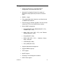
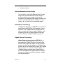
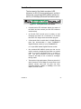
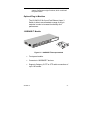
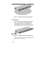
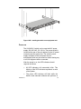
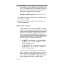
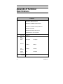
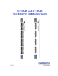
VERTICAL HORIZON VH-2402-L3 FAST ETHERNET SWITCH USER GUIDE 9033693-01 Notice 9033693-01 ii Only qualified personnel should perform installation procedures. NOTICE Enterasys Networks reserves the right to make changes in specifications and other information contained in this document without prior notice. The reader should in all cases consult Enterasys Networks to determine whether any such changes have been made. The hardware, firmware, or software described in this manual is subject to change without notice. IN NO EVENT SHALL Enterasys Networks BE LIABLE FOR ANY INCIDENTAL, INDIRECT, SPECIAL, OR CONSEQUENTIAL DAMAGES WHATSOEVER (INCLUDING BUT NOT LIMITED TO LOST PROFITS) ARISING OUT OF OR RELATED TO THIS DOCUMENT, WEB SITE, OR THE INFORMATION CONTAINED IN THEM, EVEN IF Enterasys Networks HAS BEEN ADVISED OF, KNOWN, OR SHOULD HAVE KNOWN, THE POSSIBILITY OF SUCH DAMAGES. Enterasys Networks, Inc. 500 Spaulding Turnpike Portsmouth, NH 03801 2002 Enterasys Networks, Inc. All Rights Reserved Printed in the United States of America Order Number: 9033693-01 April 2002 LANVIEW is a registered trademark of Enterasys Networks. ENTERASYS NETWORKS, NETSIGHT, MATRIX, WEBVIEW, and any logos associated therewith, are trademarks of Enterasys Networks. SPECTRUM is a registered trademark of Aprisma Management Technologies, Inc. All other product names mentioned in this manual may be trademarks or registered trademarks of their respective companies. iii 9033693-01 FCC NOTICE This device complies with Part 15 of the FCC rules. Operation is subject to the following two conditions: (1) this device may not cause harmful interference, and (2) this device must accept any interference received, including interference that may cause undesired operation. NOTE: This equipment has been tested and found to comply with the limits for a Class A digital device, pursuant to Part 15 of the FCC rules. These limits are designed to provide reasonable protection against harmful interference when the equipment is operated in a commercial environment. This equipment uses, generates, and can radiate radio frequency energy and if not installed in accordance with the operator’s manual, may cause harmful interference to radio communications. Operation of this equipment in a residential area is likely to cause interference in which case the user will be required to correct the interference at his own expense. WARNING: Changes or modifications made to this device which are not expressly approved by the party responsible for compliance could void the user’s authority to operate the equipment. INDUSTRY CANADA NOTICE This digital apparatus does not exceed the Class A limits for radio noise emissions from digital apparatus set out in the Radio Interference Regulations of the Canadian Department of Communications. Le présent appareil numérique n’émet pas de bruits radioélectriques dépassant les limites applicables aux appareils numériques de la class A prescrites dans le Règlement sur le brouillage radioélectrique édicté par le ministère des Communications du Canada. 9033693-01 iv Notice VCCI NOTICE This is a Class A product based on the standard of the Voluntary Control Council for Interference by Information Technology Equipment (VCCI). If this equipment is used in a domestic environment, radio disturbance may arise. When such trouble occurs, the user may be required to take corrective actions. CLASS A ITE NOTICE WARNING: This is a class A product. In a domestic environment this product may cause radio interference in which case the user may be required to take adequate measures. SAFETY INFORMATION CLASS 1 LASER TRANSCEIVERS The VH-2402-L3 24-port switch uses Class 1 Laser transceivers. Read the following safety information before installing or operating these modules. Class 1 laser transceivers use an optical feedback loop to maintain Class 1 operation limits. This control loop eliminates the need for maintenance checks or adjustments. The output is factory set, and does not allow any user adjustment. Class 1 Laser transceivers comply with the following safety standards: • 21 CFR 1040.10 and 1040.11 U.S. Department of Health and Human Services (FDA). • IEC Publication 825 (International Electrotechnical Commission). • CENELEC EN 60825 (European Committee for Electrotechnical Standardization). 9033693-01 v • When operating within their performance limitations, laser transceiver output meets the Class 1 accessible emission limit of all three standards. Class 1 levels of laser radiation are not considered hazardous. SAFETY INFORMATION CLASS 1 LASER TRANSCEIVERS LASER RADIATION AND CONNECTORS When the connector is in place, all laser radiation remains within the fiber. The maximum amount of radiant power exiting the fiber -6 (under normal conditions) is -12.6 dBm or 55 x 10 watts. Removing the optical connector from the transceiver allows laser radiation to emit directly from the optical port. The maximum radiance from the optical port (under worst case conditions) is 0.8 W –2 3 2 -1 cm or 8 x 10 W m sr . Do not use optical instruments to view the laser output. The use of optical instruments to view laser output increases eye hazard. When viewing the output optical port, power must be removed from the switch. WARNING: FIBER OPTIC PORT SAFETY When using a fiber optic port, never look at the transmit laser while it is powered on. Also, never look directly at the fiber TX port and fiber cable ends when they are powered on. AVERTISSMENT: PORTS POUR FIBRES OPTIQUES SÉCURITÉ SUR LE PLAN OPTIQUE Ne regardez jamais le laser tant qu'il est sous tension. Ne regardez jamais directement le port TX (Transmission) à fibres optiques et les embouts de câbles à fibres optiques tant qu'ils sont sous tension. 9033693-01 vi Notice WARNHINWEIS: FASEROPTIKANSCHLÜSSE OPTISCHE SICHERHEIT Niemals ein Übertragungslaser betrachten, während dieses eingeschaltet ist. Niemals direkt auf den Faser-TX-Anschluß und auf die Faserkabelenden schauen, während diese eingeschaltet sind. SAFETY INFORMATION WICHTIGE SICHERHEITSHINWEISE (GERMANY) 1. Bitte lesen Sie diese Hinweise sorgfältig durch. 2. Heben Sie diese Anleitung für den späteren Gebrauch auf. 3. Vor jedem Reinigen ist das Gerät vom Stromnetz zu trennen. Verwenden Sie keine Flüssigoder Aerosolreiniger. Am besten eignet sich ein angefeuchtetes Tuch zur Reinigung. 4. Die Netzanschlu ßsteckdose soll nahe dem Gerät angebracht und leicht zugänglich sein. 5. Das Gerät ist vor Feuchtigkeit zu schützen. 6. Bei der Aufstellung des Gerätes ist auf sicheren Stand zu achten. Ein Kippen oder Fallen könnte Beschädigungen hervorrufen. 7. Die Belüftungsöffnungen dienen der Luftzirkulation, die das Gerät vor Überhitzung schützt. Sorgen Sie dafür, daß diese Öffnungen nicht abgedeckt werden. 8. Beachten Sie beim Anschluß an das Stromnetz die Anschlußwerte. 9. Verlegen Sie die Netzanschlußleitung so, daß niemand darüber fallen kann. Es sollte auch nichts auf der Leitung abgestellt werden. 10. Alle Hinweise und Warnungen, die sich am Gerät befinden, sind zu beachten. 11. Wird das Gerät über einen längeren Zeitraum nicht benutzt, sollten Sie es vom Stromnetz trennen. Somit wird im Falle einer Überspannung eine Beschädigung vermieden. 12. Durch die Lüftungsöffnungen dürfen niemals Gegenstände oder Flüssigkeiten in das Gerätgelangen. Dies könnte einen Brand bzw. elektrischen Schlag auslösen. 13. Öffnen sie niemals das Gerät. Das Gerät darf aus Gründen der elektrischen Sicherheit nur von authorisiertem Servicepersonal geöffnet werden. 14. Wenn folgende Situationen auftreten ist das Gerät vom Stromnetz zu trennen und von einerqualifizierten Servicestelle zu überprüfen: a.Netzkabel oder Netzstecker sind beschädigt. b. Flüssigkeit ist in das Gerät eingedrungen. c. Das Gerät war Feuchtigkeit ausgesetzt. d. Wenn das Gerät nicht der Bedienungsanleitung entsprechend funktioniert oder Sie mit Hilfe dieser Anleitung keine Verbesserung erzielen. e. Das Gerät ist gefallen und/oder das Gehäuse ist beschädigt. f. Wenn das Gerät deutliche Anzeichen eines Defektes aufweist. 15. Zum Netzanschluß dieses Gerätes ist eine geprüfte Leitung zu verwenden. Für einen Nennstrom bis 6A und einem Gerätegewicht größer 3kg ist eine Leitung nicht leichter als H05VV-F, 3G, 0.75mm 2 einzusetzen. Der arbeitsplatzbezogene Schalldruckpegel nach DIN 45 635 Teil 1000 beträgt 70dB(A) oder weniger. 9033693-01 vii ENTERASYS NETWORKS, INC. PROGRAM LICENSE AGREEMENT BEFORE OPENING OR UTILIZING THE ENCLOSED PRODUCT, CAREFULLY READ THIS LICENSE AGREEMENT. BEFORE OPENING OR UTILIZING THE ENCLOSED PRODUCT, CAREFULLY READ THIS LICENSE AGREEMENT. This document is an agreement (“ Agreement” ) between You, the end user, and Enterasys Networks, Inc. (“ Enterasys” ) that sets forth your rights and obligations with respect to the Enterasys software program (“Program” ) in the package. The Program may be contained in firmware, chips or other media. UTILIZING THE ENCLOSED PRODUCT, YOU ARE AGREEING TO BECOME BOUND BY THE TERMS OF THIS AGREEMENT, WHICH INCLUDES THE LICENSE AND THE LIMITATION OF WARRANTY AND DISCLAIMER OF LIABILITY. IF YOU DO NOT AGREE TO THE TERMS OF THIS AGREEMENT, RETURN THE UNOPENED PRODUCT TO ENTERASYS OR YOUR DEALER, IF ANY, WITHIN TEN (10) DAYS FOLLOWING THE DATE OF RECEIPT FOR A FULL REFUND. IF YOU HAVE ANY QUESTIONS ABOUT THIS AGREEMENT, CONTACT ENTERASYS NETWORKS (603) 332-9400. Attn: Legal Department. 1. LICENSE. You have the right to use only the one (1) copy of the Program provided in this package subject to the terms and conditions of this License Agreement. You may not copy, reproduce or transmit any part of the Program except as permitted by the Copyright Act of the United States or as authorized in writing by Enterasys. 2. OTHER RESTRICTIONS. You may not reverse engineer, decompile, or disassemble the Program. 3. APPLICABLE LAW. This License Agreement shall be interpreted and governed under the laws and in the state and federal courts of New Hampshire. You accept the personal jurisdiction and venue of the New Hampshire courts. 4. EXPORT REQUIREMENTS. You understand that Enterasys and its Affiliates are subject to regulation by agencies of the U.S. Government, including the U.S. Department of Commerce, which prohibit export or diversion of certain technical products to certain countries, unless a license to export the product is obtained from the U.S. Government or an exception from obtaining such license may be relied upon by the exporting party. If the Program is exported from the United States pursuant to the License Exception CIV under the U.S. Export Administration Regulations, You agree that You are a civil end user of the Program and agree that You will use the Program for civil end uses only and not for military purposes. 9033693-01 viii Notice If the Program is exported from the United States pursuant to the License Exception TSR under the U.S. Export Administration Regulations, in addition to the restriction on transfer set forth in Sections 1 or 2 of this Agreement, You agree not to (i) reexport or release the Program, the source code for the Program or technology to a national of a country in Country Groups D:1 or E:2 (Albania, Armenia, Azerbaijan, Belarus, Bulgaria, Cambodia, Cuba, Estonia, Georgia, Iraq, Kazakhstan, Kyrgyzstan, Laos, Latvia, Libya, Lithuania, Moldova, North Korea, the People’s Republic of China, Romania, Russia, Rwanda, Tajikistan, Turkmenistan, Ukraine, Uzbekistan, Vietnam, or such other countries as may be designated by the United States Government), (ii) export to Country Groups D:1 or E:2 (as defined herein) the direct product of the Program or the technology, if such foreign produced direct product is subject to national security controls as identified on the U.S. Commerce Control List, or (iii) if the direct product of the technology is a complete plant or any major component of a plant, export to Country Groups D:1 or E:2 the direct product of the plant or a major component thereof, if such foreign produced direct product is subject to national security controls as identified on the U.S. Commerce Control List or is subject to State Department controls under the U.S. Munitions List. 5. UNITED STATES GOVERNMENT RESTRICTED RIGHTS. The enclosed Product (i) was developed solely at private expense; (ii) contains ‘‘restricted computer software’’ submitted with restricted rights in accordance with section 52.227-19 (a) through (d) of the Commercial Computer Software-Restricted Rights Clause and its successors, and (iii) in all respects is proprietary data belonging to Enterasys and/or its suppliers. For Department of Defense units, the Product is considered commercial computer software in accordance with DFARS section 227.7202-3 and its successors, and use, duplication, or disclosure by the Government is subject to restrictions set forth herein. 6. EXCLUSION OF WARRANTY. Except as may be specifically provided by Enterasys in writing, Enterasys makes no warranty, expressed or implied, concerning the Program (including its documentation and media). ENTERASYS DISCLAIMS ALL WARRANTIES, OTHER THAN THOSE SUPPLIED TO YOU BY ENTERASYS IN WRITING, EITHER EXPRESS OR IMPLIED, INCLUDING BUT NOT LIMITED TO IMPLIED WARRANTIES OF MERCHANTABILITY AND FITNESS FOR A PARTICULAR PURPOSE, WITH RESPECT TO THE PROGRAM, THE ACCOMPANYING WRITTEN MATERIALS, AND ANY ACCOMPANYING HARDWARE. 7. NO LIABILITY FOR CONSEQUENTIAL DAMAGES. IN NO EVENT SHALL ENTERASYS OR ITS SUPPLIERS BE LIABLE FOR ANY DAMAGES WHATSOEVER (INCLUDING, WITHOUT LIMITATION, DAMAGES FOR LOSS OF BUSINESS, PROFITS, BUSINESS INTERRUPTION, LOSS OF BUSINESS INFORMATION, SPECIAL, INCIDENTAL, CONSEQUENTIAL, OR RELIANCE DAMAGES, OR OTHER LOSS) ARISING OUT OF THE USE OR INABILITY TO USE THIS ENTERASYS PRODUCT, EVEN IF ENTERASYS HAS BEEN ADVISED OF THE POSSIBILITY OF SUCH DAMAGES. BECAUSE SOME STATES DO NOT ALLOW THE EXCLUSION OR LIMITATION OF LIABILITY FOR CONSEQUENTIAL OR INCIDENTAL DAMAGES, OR IN THE DURATION OR LIMITATION OF IMPLIED WARRANTIES IN SOME INSTANCES, THE ABOVE LIMITATION AND EXCLUSIONS MAY NOT APPLY TO YOU. 9033693-01 ix DECLARATION OF CONFORMITY Application of Council Directive(s): 89/336/EEC 73/23/EEC Manufacturer’s Name: Manufacturer’s Address: European Representative Address: Enterasys Networks, Inc. 500 Spaulding Turnpike PO Box 3060 Portsmouth, NH 03801 Enterasys Networks Ltd. Nexus House, Newbury Business Park London Road, Newbury Berkshire RG14 2PZ, England Conformance to Directive(s)/Product Standards: EC Directive 89/336/EEC EC Directive 73/23/EEC EN 55022 EN 55024 EN 60950 EN 60825 Equipment Type/Environment: Networking Equipment, for use in a Commercial or Light Industrial Environment. Enterasys Networks, Inc. declares that the equipment packaged with this notice conforms to the above directives. 9033693-01 10 Table of Contents PREFACE ............................................................................. 13 Purpose...................................................................... 13 Audience.................................................................... 13 Conventions .............................................................. 13 Organization................................................................ 15 PRODUCT OVERVIEW ...................................................... 16 Description................................................................. 16 Layer 3 Switching ..................................................... 16 The Functions of a Layer 3 Switch ........................ 18 Features..................................................................... 19 Ports ........................................................................... 19 Performance Features............................................. 20 Layer 2 Features ...................................................... 20 Layer 3 Switch Features ......................................... 22 Traffic Classification and Prioritization...................... 22 Management................................................................ 23 Optional Redundant Power Supply ....................... 24 Fast Ethernet Technology....................................... 24 Gigabit Ethernet Technology...................................... 24 Front Panel .................................................................. 25 Rear Panel.................................................................. 26 Side Panels ................................................................. 26 Optional Plug-in Modules........................................ 27 1000BASE-T Module ............................................... 27 1000BASE-SX Fiber Module.................................. 28 GBIC Two-Port Module ........................................... 28 LED Indicators .......................................................... 29 Feature Summaries ................................................. 29 Factory Defaults ....................................................... 33 2. INSTALLATION.............................................................. 35 9033693-01 11 Inspecting Your Shipment....................................... 35 Installation ................................................................. 36 Desktop or Shelf Installation................................... 36 Rack Installation ....................................................... 37 Power on.................................................................... 38 Power Failure............................................................ 39 3. CONNECTING THE SWITCH ...................................... 40 Switch to End Node .................................................... 40 Switch to Hub or Switch ............................................. 41 10BASE-T Device .................................................... 42 100BASE-TX Device ............................................... 42 APPENDIX A. TECHNICAL SPECIFICATIONS ............ 43 APPENDIX B. FLOW CONTROL..................................... 46 APPENDIX C. ACRONYMS AND ABBREVIATIONS .. 48 INDEX.................................................................................... 50 9033693-01 12 Preface Purpose This guide provides information about the features and applications of the Enterasys Networks Vertical Horizon VH-2402-L3 layer 3 switch. Audience This guide is intended for Ethernet Local Area Network (LAN) administrators and Management Information Systems (MIS) personnel with the following background: • Working knowledge of Ethernet LANs • Familiarity with Transmission Control Protocol/Internet Protocol (TCP/IP) and Simple Network Management Protocol (SNMP) Conventions This section describes the conventions used in this guide. Message Formats Two types of messages, identified by icons, appear in the text A note informs you of special circumstances. 9033693-01 13 A caution indicates the possibility of equipment damage Keyboard Entries This guide uses the following conventions for keyboard entries: • When you read “enter”, type the text and press the [Enter] key. • Example: Enter the Gateway IP address and press the [Enter] key. • When you read “select”, highlight the menu item and press the [Enter] key. Other Conventions This guide uses the following typographical conventions: • Initial Caps selections. Menu titles and console • [Enter] Used to designate the Enter or Return key. • Courier font Screen messages and user prompts. • Selection Describes a user-configurable interface item. • Field Describes a read-only information item. 9033693-01 14 Organization Chapter 1. Product Overview: Describes the features of the switch, front and rear panel components and application examples. Chapter 2. Installation: Describes the content of your switch shipment, lists site requirements, and provides mounting instructions. Instructions for making connections and powering up the switch are provided as well. Appendix A. Technical Specifications: Provides a list of standards compliance and certifications as well as physical and operational specifications. Appendix B. Flow Control: Describes how the flow control features are used to provide a mechanism for protecting the switch from overload conditions and to keep additional traffic off the network. Appendix C. Acronyms and Abbreviations: Provides definitions for a list of common acronyms and abbreviations used within the installation guide and the networking industry. 9033693-01 15 Product Overview This chapter provides the following information: • Product Description • Features • Front and Rear Panel Component Descriptions • Feature Summaries • Application Example Description This installation guide describes Enterasys Networks’ Vertical Horizon VH-2402-L3 Fast Ethernet switch. The switch provides 24 10Base-T/100Base-TX ports, plus one slot for optional slide-in 1000Base-SX 1000Base-T and GBIC modules. The switch features a built in SNMP-based Management agent. The VH-2402-L3 support both Layer 2 as well as Layer 3 functionality. Layer 3 Switching Layer 3 switching is an integration of two proven technologies: switching and routing. In fact, Layer 3 switches are running the same routing routines and protocols as traditional routers. The main difference between traditional routing and Layer 3 switching is the addition of a group of Layer 2 switching domains and the execution of routing routines for most packets via an ASIC – in hardware instead of software. 16 9033693-01 Where a traditional router would have one, or at best a few, Fast Ethernet ports, the VH-2402-L3 Layer 3 switch has 24 Fast Ethernet ports and optionally, 2 Gigabit Ethernet ports. Where a traditional router would have one or two high-speed serial WAN connections, the VH-2402-L3 relies upon a Fast Ethernet port to connect to a separate device, which in turn, connects the network to a WAN or the Internet. The VH-2402-L3 can be thought of as 24 Fast Ethernet Layer 2 switching domains with a wire-speed router between each domain. It can be deployed in a network between a traditional router and the intranetwork. The traditional router and its associated WAN interface would then handle routing between the intranetwork and the WAN (the Internet, for example) while the Layer 3 switch would handle routing within the LAN (between the Fast Ethernet Layer 2 domains). Any installed Layer 2 switches, and indeed the entire subnetting scheme, would remain in place. The VH-2402-L3 can also replace key traditional routers for data centers and server farms, routing between these locations and the rest of the network, and providing 24 ports of Layer 2 switching performance combined with wire-speed routing. Backbone routers can also be replaced with the VH-2402-L3 via optional Gigabit Ethernet ports on the VHIM uplink modules. Routers that service WAN connections would remain in place, but would now be removed from the backbone and connected to the VH-2402-L3 via an Ethernet/Fast Ethernet port. The backbone itself could be migrated to Gigabit Ethernet, or faster technologies as they become available. Policy services can then be introduced (or enhanced) in the backbone infrastructure and maintained throughout the network – even to the desktop. With a 9033693-01 17 distributed infrastructure and a logical management structure, network performance becomes easier to measure and fine-tune. With the completion of the migration of the backbone to Gigabit or higher-performance technologies, the result is inherently scalable and easily evolved for future technologies. This core network will also become the termination point for Virtual Private Networks (VPNs) for remote office access to the enterprise infrastructure. The VH-2402-L3 can then be thought of as accomplishing two objectives. First as a tool to provide high-performance access to enterprise data servers and infrastructure, and second, to enhance the performance of network equipment already installed. Many network segments display poor performance, but the Ethernet wire is only carrying a fraction of its total traffic capacity. The problem is not the network, but the ability of the connected devices utilize the full capacity of the network. The VH-2402-L3 can eliminate network bottlenecks to high-traffic areas, and improve the utilization of the network’s installed bandwidth. The Functions of a Layer 3 Switch Traditional routers, once the core components of large networks, became an obstacle to the migration toward next-generation networks. Attempts to make softwarebased routers forward packets more quickly were inadequate. A layer 3 switch does everything to a packet that a traditional router does: • 9033693-01 Determines forwarding path based on Layer 3 information 18 • Validates the integrity of the Layer 3 header via checksum • Verifies packet expiration and updates accordingly • Processes and responds to any optional information • Updates forwarding statistics in the Management Information Base • Applies security controls A Layer 3 switch can be placed anywhere within a network core or backbone, easily and cost-effectively replacing the traditional collapsed backbone router. The VH-2402-L3 Layer 3 switch communicates with a WAN router using a standard Ethernet/Fast Ethernet port. Multiple VH-2402-L3 switches can be linked via the optional, 2-port Gigabit Ethernet module. Features The VH-2402-L3 Switch was designed for easy installation and high performance in an environment where traffic on the network and the number of users increase continuously. Switch features include: Ports • 24 high performance ports all operating at 10/100 Mbps for connecting to end stations, servers and hubs (23 MDI-X 10/100 Ethernet UTP ports and one MDI-II/MDI-X port. The MDI-II/MDI-X port can be switched between the two modes from the front panel.) • All ports can auto-negotiate between 10Mbps/ 100Mbps, half-duplex or full duplex and flow control for half-duplex ports. 9033693-01 19 • One front panel slide-in module interface for a 2-port 1000BASE-SX, , 1000BASE-T, or GBIC Gigabit Ethernet module. • RS-232 DCE Diagnostic port (console port) for setting up and managing the Switch via a connection to a console terminal or PC using a terminal emulation program. Performance Features Layer 2 Features • 8.8 Gbps switching fabric capacity • Store and forward switching scheme. • Full and half-duplex for both 10Mbps and 100Mbps connections. The front-port Gigabit Ethernet module operates at full-duplex only. Full-duplex allows the switch port to simultaneously transmit and receive data, and only works with connections to full-duplex capable end stations and switches. Connections to hubs must take place at half-duplex. • Supports IEEE 802.3x flow control for full-duplex mode ports. • Supports Back-pressure flow control for half-duplex mode ports. • Auto-polarity detection and correction of incorrect polarity on the transmit and receive twisted-pair at each port. • IEEE 802.3z compliant for all Gigabit ports (optional module). • IEEE 802.3x compliant Flow Control support for all Gigabit ports (optional module). • IEEE 802.3u compliant for 1000BASE-T (Copper) Gigabit ports (optional module). 9033693-01 20 • IEEE 802.3ab compliant for 1000BASE-T (Copper) Gigabit ports (optional module). • Data forwarding rate 14,880 pps per port at 100% of wire-speed for 10Mbps speed. • Data forwarding rate 148,800 pps per port at 100% of wire-speed for 100Mbps speed. • Data filtering rate eliminates all error packets, runts, etc. at 14,880 pps per port at 100% of wire-speed for 10Mbps speed. • Data filtering rate eliminates all error packets, runts, etc. at 148,800 pps per port at 100% of wire-speed for 100Mbps speed. • 8K active MAC address entry table per device with automatic learning and aging (10 to 9999 seconds). • 16 MB packet buffer per device. • Broadcast and Multicast storm filtering. • Supports Port Mirroring. • Supports Port Trunking – up to six trunk groups • 802.1D Spanning Tree support. • 802.1Q Tagged VLAN support – up to 63 User-defined VLANs per device (one VLAN is reserved for internal use). • GVRP – (GARP VLAN Registration Protocol) support for dynamic VLAN registration. • 802.1p Priority support with 4 priority queues. • IGMP Snooping support. • Layer 2 Multicast support – GMRP (GARP Multicast Registration Protocol). 9033693-01 21 Layer 3 Switch Features • Wire speed IP forwarding. • Hardware-based Layer 3 IP switching. • IP packet forwarding rate of 6.6 Mpps. • 2K active IP address entry table per device. • Supports RIP – (Routing Information Protocol) version I and II. • Supports IP version 4. • IGMP version 1 and 2 support (RFC 1112 and RFC 2236). IGMP can be globally enabled or disabled for all VLANs. • Supports PIM Dense Mode. • Supports DVMRP. • Supports Username to IP address mapping. • Supports IP multi-netting. • Supports IP packet de-fragmentation. • Supports Path MTU discovery. • Supports 802.1D frame support. Traffic Classification and Prioritization • Based on 802.1p priority bits • Based on IP source and destination addresses • 4 priority queues 9033693-01 22 Management • RS-232 console port for out-of-band network management via a console terminal or PC. • Spanning Tree Algorithm Protocol for creation of alternative backup paths and prevention of network loops. • SNMP v.1 Agent. • Fully configurable either in-band or out-of-band control via SNMP based software. • Flash memory for software upgrades. This can be done in-band via TFTP or out-of-band via the console. • Built-in SNMP management: Bridge MIB (RFC 1493), RMON MIB (RFC 1757), and MIB-II (RFC 1213) MIB-II (RFC 1213, RFC 1573) and Ethernet interface MIB (RFC 1643). Entity MIB (RFC 1286). RMON MIB (RFC 1757) – Statistics, History, Alarm, and Event. CIDR MIB (RFC 2096). 802.1p MIB (RFC 2674). • Supports Web-based management. • Supports RMON 4 groups. • TFTP support. • BOOTP support. • IP filtering on the management interface. • DCHP Client support. 9033693-01 23 • DCHP Relay Agent. • Password enabled. Optional Redundant Power Supply The VH-2402-L3, 24+2 Fast Ethernet Layer 3 Switch supports the optional Redundant Power Supply to provide automatic power supply monitoring and switchover to a redundant power supply (located in the chassis of the Redundant Power Supply) in case of a failure in the VH-2402-L3’s internal power supply. Fast Ethernet Technology 100Mbps Fast Ethernet (or 100BASE-T) is a standard specified by the IEEE 802.3 LAN committee. It is an extension of the 10Mbps Ethernet standard with the ability to transmit and receive data at 100Mbps, while maintaining the Carrier Sense Multiple Access with Collision Detection (CSMA/CD) Ethernet protocol. Gigabit Ethernet Technology Gigabit Ethernet is an extension of IEEE 802.3 Ethernet utilizing the same packet structure, format, and support for CSMA/CD protocol, full duplex, flow control, and management objects, but with a tenfold increase in theoretical throughput over 100Mbps Fast Ethernet and a one hundred-fold increase over 10Mbps Ethernet. Since it is compatible with all 10Mbps and 100Mbps Ethernet environments, Gigabit Ethernet provides a straightforward upgrade without wasting a company’s existing investment in hardware, software, and trained personnel. 9033693-01 24 Front Panel The front panel of the Switch consists of LED indicators, an RS-232 communication port, a slide-in module slot, one switched MDI-X/MDI-II uplink port, and 23 (10/100 Mbps) Ethernet/Fast Ethernet ports. Figure 1-1. Front panel view of the Switch • Comprehensive LED indicators display the status of the switch and the network (see the LED Indicators section below). • An RS-232 DCE console port for setting up and managing the switch via a connection to a console terminal or PC using a terminal emulation program. • A front-panel slide-in module slot for Gigabit Ethernet ports can accommodate a 2-port 1000BASE-T Gigabit Ethernet module, a 2-port 1000BASE-SX , or a 2-port GBIC-based Gigabit Ethernet module. • One switched MDI-X/MDI-II Uplink port that can be used to connect a straight-through cable or a crossed cable to a normal (non-Uplink) port on a switch or hub. This port is identical to the other 23 ports except for the ability to use a crossed or a straightthrough cable. • Twenty-three high-performance, Ethernet ports all of which operate at 10/100 Mbps for connections to end stations, servers and hubs. All ports can autonegotiate between 10Mbps or 100Mbps, full or half duplex, and flow control. 9033693-01 25 Rear Panel The rear panel of the switch consists of a slot for the optional Redundant Power Supply and an AC power connector. Figure 1-2. Rear panel view of the Switch • The AC power connector is a standard three-pronged connector that supports the power cord. Plug-in the female connector of the provided power cord into this socket, and the male side of the cord into a power outlet. Supported input voltages range from 100 ~ 240 VAC at 50 ~ 60 Hz. Side Panels The right side panel of the Switch contains two system fans (see the top part of the diagram below). The left side panel contains heat vents. Figure 1-3. Side panel views of the Switch • 9033693-01 The system fans are used to dissipate heat. The sides of the system also provide heat vents to serve the same purpose. Do not block these openings, and leave at least 6 inches of space at the rear and sides of the switch for proper ventilation. Be reminded that 26 without proper heat dissipation and air circulation, system components might overheat, which could lead to system failure. Optional Plug-in Modules The VH-2402-L3 24+2-port Fast Ethernet Layer 3 Switch is able to accommodate a range of plug-in modules in order to increase functionality and performance. 1000BASE-T Module Figure 1-5. 1000BASE-TX two-port module • Front-panel module. • Connects to 1000BASE-T devices. • Supports Category 5 UTP or STP cable connections of up to 100 meters. 9033693-01 27 1000BASE-SX Fiber Module Figure 1-6. 1000BASE-SX two-port module • Front-panel module. • Connects to 1000BASE-SX devices at full-duplex. • Supports multi-mode fiber-optic cable connections of up to 412 meters in half-duplex or 2 km in fullduplex mode. GBIC Two-Port Module Figure 1-8. GBIC two-port module • Front-panel module. • Connects to GBIC devices at full duplex only. • 9033693-01 Allows multi-mode fiber optic cable runs of up to 2km in full-duplex mode (only). 28 LED Indicators The LED indicators of the Switch include Power, Console, and Link/Act. The following shows the LED indicators for the Switch along with an explanation of each indicator. Figure 1-9. The LED indicators • Power This indicator on the front panel should be colored amber during the Power-On Self Test (POST). It will light green approximately 2 seconds after the switch is powered on to indicate the ready state of the device. The LED will blink green while downloading new software for the switch, or if the system’s configuration has changed and will light yellow when an error occurs. • RDP in use When link with redundant power supply, the “RDP in use” LED will blink in orange. • Act/Link These indicators are located to the left of each port. They are lit when there is a secure connection (or link) to a device at any of the ports. The LEDs blink whenever there is reception or transmission (i.e. Activity--Act) of data occurring at a port. Feature Summaries The following summaries describe VH-2402-L3 features in areas such as standards compliance, functionality, performance, and options. Local Console Management A local console is a terminal or a workstation running a terminal emulation program that is connected directly to the switch via the RS-232 console port on the front of the switch. A console connection is referred to as an 9033693-01 29 ‘Out-of-Band’ connection, meaning that console is connected to the switch using a different circuit than that used for normal network communications. So, the console can be used to set up and manage the switch even if the network is down. Local console management uses the terminal connection to operate the console program built-in to the switch. A network administrator can manage, control and monitor the switch from the console program. The VH-2402-L3 contains a CPU, memory for data storage, flash memory for configuration data, operational programs, and SNMP agent firmware. These components allow the switch to be actively managed and monitored from either the console port or the network itself (out-of-band, or in-band). SNMP Management The Simple Network Management Protocol (SNMP) is an OSI layer 7 (the application layer) protocol for remotely monitoring and configuring network devices. SNMP enables network management stations to read and modify the settings of gateways, routers, switches, and other network devices. SNMP can be used to perform many of the same functions as a directly connected console, or can be used within an integrated network management software package such as NetSight. Flow Control The VH-2402-L3 supports flow control (back pressure handling) on a per-port basis. The limit at which flow control is applied to a port is based on the amount of memory used by the packets on an input port. The limit is 9.6 kb and whenever this limit is reached, flow control is applied: 9033693-01 30 • 802.3x Flow Control – if the port is configured in full duplex mode, a MAC PAUSE packet is sent to inhibit the flow of packets to the port for a short amount of time. • Enable Jamming Signal – if the port is configured in half duplex mode, a jamming signal is sent for a short amount of time. Spanning Tree Protocol The VH-2402-L3 switch complies with the IEEE 802.1D Spanning Tree Protocol standard and allows for the blocking of links between switches that form loops within the network. When multiple links between switches are detected, a primary link is established. Duplicated links are blocked from use and become standby links. The protocol allows for the duplicate links to be used in the event of a failure of the primary link. Once the Spanning Tree Protocol is configured and enabled, primary links are established and duplicated links are blocked automatically. The reactivation of the blocked links (at the time of a primary link failure) is also accomplished automatically – without operator intervention. Port Trunking Port trunking is used to combine a number of ports together to make a single high-bandwidth data pipeline. The participating parts are called members of a Port Trunking group, with one port designated as the master port of the group. Since all members of the Port Trunking group must be configured to operate in the same manner, the configuration of the master port is applied to all members of the Port Trunking group. Thus, when configuring the ports in a Port Trunking group, you only need to configure the master port. 9033693-01 31 The VH-2402-L3 supports 6 Port Trunking groups, which may include from 2 to 8 switch ports each, except for a Gigabit Port Trunking group which consists of the 2 (optional) Gigabit Ethernet ports of the front panel. These ports are the two 1000BASE-SX, -TX or GBIC ports contained in a front-panel mounted module. IEEE 802.1Q VLANs IEEE 802.1Q (tagged) VLANs are implemented on the VH-2402-L3. 802.1Q VLANs allow tagging, which enables them to span the entire network (assuming all switches on the network are IEEE 802.1Q-compliant). IEEE 802.1Q VLANs also allow for dynamic VLAN registration using GVRP. VLANs allow a network to be segmented in order to reduce the size of broadcast domains. All packets entering a VLAN will only be forwarded to the stations (over IEEE 802.1Q enabled switches) that are members of that VLAN, and this includes broadcast, multicast and unicast packets from unknown sources. VLANs can also provide a level of security to your network. IEEE 802.1Q VLANs will only deliver packets between stations that are members of the VLAN. Broadcast Storm Control Broadcast storms consist of broadcast packets that flood and/or are looped on a network causing noticeable performance degradation and in extreme cases, network failure. Broadcast storms can be caused by malfunctioning NICs, bad cable connections and applications or protocols that generate broadcast traffic, among others. Broadcast storms have long been a concern for network administrators with routers traditionally being 9033693-01 32 used to prevent their occurrence, and if that failed, limit their scope. However, with the advent of VLANs, switches are now able to limit broadcast domains better and cheaper than routers. The VH-2402-L3 switch has broadcast sensors and filters built into each port to control broadcast storms. IP Routing IP is responsible for getting packets to the destination specified in the destination address. The task of determining how to get a packet from the source to the destination is referred to as routing. The VH-2402-L3 allows the creation of IP subnets and can perform IP routing between them. Each IP subnet corresponds to an IEEE 802.1Q VLAN, previously defined on the switch. Factory Defaults Table 1-1 lists the default settings for the switch configuration parameters. Each parameter can be changed via the console menus or Telnet. Table 1-1. Factory Default Settings Parameter Load Mode Switch Operation Mode Configuration update Firmware update Configuration file name Firmware file name Out-of-band baud rate RS232 mode IP address Subnet mask Default Gateway 9033693-01 Default Value Ethernet Layer 2 Disable Disable None None 9600 Console 10.90.90.90 0.0.0.0 0.0.0.0 33 BootP service TFTP server IP address IGMP time out IGMP capture state Partition mode Address table lock Device HOL Port HOL Console time out User name Password Device STP Port STP Port enable Bridge max age Bridge hello time Bridge forward delay Bridge priority Port STP cost Port STP priority Forwarding table aging time Address lookup mode Enable 0.0.0.0 260 secs Disable Enable Disable Disable Enable 15 min Admin None Disable Enable Enable 20 secs 2 sec 15 sec 32768 19 (Gigabit=4) 128 300 secs Level 1 Flow control Backpressure Port lock Port priority Broadcast storm rising action Broadcast storm falling action Broadcast storm rising threshold Broadcast storm falling threshold Community string VLAN mode SNMP VLAN(802.1Q) Default port VID Ingress rule checking Disable Disable Disable Default Do nothing Do nothing 128Kpps < 128Kpps “public”, “private” IEEE 802.1Q 1 1 Disable 9033693-01 34 Mirror src port <->target port Mirror 1Å2 Disable 2. Installation Inspecting Your Shipment Open the shipping carton of the Switch and carefully unpack its contents. The carton should contain the following items: • 9033693-01 One VH-2402-L3 24+2-port Fast Ethernet Layer 3 Switch 35 • Mounting kit: 2 mounting brackets and screws • Four rubber feet with adhesive backing • ESD wrist strap • One AC power cord • Product documentation If any item is found missing or damaged, please contact your local Enterasys Sales Representative for replacement. Installation Use the following guidelines when choosing a place to install the Switch: • The surface must support at least 3 kg. • The power outlet should be within 1.82 meters (6 feet) of the device. • Visually inspect the power cord and see that it is secured to the AC power connector. • Make sure that there is proper heat dissipation from and adequate ventilation around the switch. Do not place heavy objects on the switch. Desktop or Shelf Installation When installing the Switch on a desktop or shelf, the rubber feet included with the device should first be attached. Attach these cushioning feet on the bottom at each corner of the device. Allow adequate space for ventilation between the device and the objects around it. 9033693-01 36 Figure 2-1. Installing rubber feet for desktop installation Rack Installation The VH-2402-L3 can be mounted in an EIA standardsized, 19-inch rack, which can be placed in a wiring closet with other equipment. To install, attach the mounting brackets on the switch’s side panels (one on each side) and secure them with the screws provided. Figure 2- 2A. Attaching the mounting brackets to the switch Then, use the screws provided with the equipment rack to mount the switch on the rack. 9033693-01 37 Figure 2-2B. Installing the switch on an equipment rack Power on The VH-2402-L3 switch can be used with AC power supply 100-240 VAC, 50 - 60 Hz. The power switch is located at the rear of the unit adjacent to the AC power connector and the system fan. The switch’s power supply will adjust to the local power source automatically and may be turned on without having any or all LAN segment cables connected. After the power is on, the LED indicators should respond as follows: • All LED indicators will momentarily blink. This blinking of the LED indicators represents a reset of the system. • The power LED indicator will blink while the Switch loads onboard software and performs a 9033693-01 38 self-test. After approximately 20 seconds, the LED will light again to indicate the switch is in a ready state. • The RDP in use LED When link with redundant power supply, the “RDP in use” LED will blink in orange. • The 100M LED indicator may remain ON or OFF depending on the transmission speed. Power Failure As a precaution in the event of a power failure, unplug the switch. When power is resumed, plug the switch back in. 9033693-01 39 3. Connecting The Switch This chapter describes how to connect the VH-2402-L3 to your Fast Ethernet network. Switch to End Node End nodes include PCs outfitted with a 10, 100 or 10/100 Mbps RJ-45 Ethernet/Fast Ethernet Network Interface Card (NIC) and most routers. The RJ-45 UTP ports on NICs and most routers are MDI-II. When using a normal straight-through cable, an MDI-II port must connect to an MDI-X port. An end node can be connected to the Switch via a twopair Category 3, 4, 5 UTP/STP straight cable (be sure to use Category 5 UTP or STP cabling for 100 Mbps Fast Ethernet connections). The end node should be connected to any of the twenty-three ports (2x - 24x) of the VH-2402-L3 or to either of the two 100BASE-TX ports on the front-panel module that came preinstalled on the switch. Port 1x can be used as an uplink port to connect to another switch using either a crossed or a straight-through cable. This port is switched between MDI-X and MDI-II to accommodate either type of cable. Figure 3-1. Switch connected to an End Node 9033693-01 40 The LED indicators for the port the end node is connected to are lit according to the capabilities of the NIC. If LED indicators are not illuminated after making a proper connection, check the PC’s LAN card, the cable, switch conditions, and connections. The following LED indicator states are possible for an end node to switch connection: 1. The 100M LED indicator comes ON for a 100 Mbps and stays OFF for 10 Mbps. 2. The Link/Act LED indicator lights up upon hooking up a PC that is powered on. Switch to Hub or Switch These connections can be accomplished in a number of ways. The most important consideration is that when using a normal, straight-through cable, the connection should be made between a normal crossed port (Port 2x, 3x, etc.) and an Uplink (MDI-II) port. If you are using a crossover cable, the connection must be made from Uplink to Uplink (port 1x on the VH-2402-L3), or from a crossed port to another crossed port. • A 10BASE-T hub or switch can be connected to the Switch via a two-pair Category 3, 4 or 5 UTP/STP straight cable. • A 100BASE-TX hub or switch can be connected to the Switch via a two-pair Category 5 UTP/STP straight cable. If the other switch or hub contains an unused Uplink port, we suggest connecting the other device’s Uplink (MDI-II) port to any of the switch’s (MDI-X) ports (1x 22x, or one of the 100BASE-TX module ports) using a normal straight-through cable, as shown below. 9033693-01 41 If the other device does not have an unused Uplink port, make the connection with a normal straightthrough cable from the Uplink port on the switch to any normal crossed port on the hub. Alternatively, if you have a crossover cable you can save the Uplink ports for other connections and make this one from a crossed port to another crossed port. Figure 3-2. Switch connected to a normal (non-Uplink) port on a hub or switch using a straight or crossover cable 10BASE-T Device For a 10BASE-T device, the Switch’s LED indicators should display the following: • 100M LED speed indicator is OFF. • Link/Act indicator is ON. 100BASE-TX Device For a 100BASE-TX device, the Switch’s LED indicators should display the following: • 100M LED speed indicator is ON. • Link/Act is ON. 9033693-01 42 Appendix A. Technical Specifications General Standards: IEEE 802.3 10BASE-T Ethernet IEEE 802.3u 100BASE-TX Fast Ethernet IEEE 802.3z 1000BASE-SX Gigabit Ethernet IEEE 802.1 P/Q VLAN IEEE 802.3x Full-duplex Flow Control ANSI/IEEE 802.3 f auto-negotiation Protocols: CSMA/CD Data Transfer Rates: Half-duplex Full-duplex Ethernet 10 Mbps 20Mbps Fast Ethernet 100Mbps 200Mbps Gigabit Ethernet n/a 2000Mbps Topology: 43 Star 9033693-01 General (Cont’d) Network Cables: 10BASE-T: 100BASE-TX: Fiber Optic: Number of Ports: 2-pair UTP Cat. 3,4,5 (100 m) EIA/TIA- 568 100-ohm STP (100 m) 2-pair UTP Cat. 5 (100 m) EIA/TIA-568 100-ohm STP (100 m) IEC 793-2:1992 Type A1a - 50/125um multimode Type A1b - 62.5/125um multimode Both types use MT-RJ or SC optical connector 24 x 10/100 Mbps ports 2 Gigabit Ethernet (optional) Physical and Environmental AC inputs: 100 - 240 VAC, 50/60 Hz (internal universal power supply) Power Consumption: 40 watts maximum DC fans: 3 built-in 40 x 40 x10 mm fan Operating Temperature: 0 to 50 degrees Celsius Storage Temperature: -25 to 55 degrees Celsius Humidity: Operating: 5% to 95% RH noncondensing; Storage: 0% to 95% RH non-condensing Dimensions: 441 mm x 207 mm x 44 mm (1U), 19 inch rack-mount width Weight: 3 kg EMI: FCC Class A, CE Class A, VCCI Class A, BSMI Class A, C-Tick Class A FCC Part 15/IECES-003 (Canada), VCCI Class A ITE, EN55022/EN50082-1 or EN%%o24, C-Tick (AS/NZS3548, BSMI (CNS 13438) 9033693-01 44 General (Cont’d) Safety: UL, CSA, CE Mark, TUV/GS UL 1950 & CSA22.2 No 950, IEC 950 (CB), TUV (EN60950) Performance Transmission Method: Store-and-forward RAM Buffer: 16 MB per device Filtering Address Table: 8K MAC address per device Packet Filtering/ Forwarding Rate: Full-wire speed for all connections. 148,800 pps per port (for 100Mbps) 1,488,000 pps per port (for 1000Mbps) MAC Address Learning: Forwarding Table Age Time: 9033693-01 Automatic update. Max age:10–9999 seconds. Default = 300. 45 Appendix B. Flow Control Flow control is a mechanism which allows you to protect the switch from overload conditions and to keep additional traffic off the network when excessive congestion will result. Flow Control for Half- and Full-Duplex Applications Each port of the switch has a transmit queue which buffers frames to be sent out on that port. In this example, large amounts of data are being sent from Workstation A (connected to port X) and other ports on the switch to Workstation B (connected to port Y).The queue on port Y starts filling up with data until it reaches a determined threshold. The packet which causes the threshold to be exceeded triggers the flowcontrol function on the port from which the packet entered the switch, in this case port X. Since port X is configured with flow control set to Enabled, the switch responds by initiating a pause frame (full-duplex applications) or back-pressure mechanism (half-duplex applications). The pause frame causes Workstation A to stop sending packets. After a certain amount of time has elapsed, determined by a value in the pause frame, Workstation A will resume sending data. Similarly, the back-pressure mechanism forces Workstation A to stop sending packets by inducing collisions on port X. The pause-frame flow-control mechanism supported by the VH-2402-L3 switch conforms with the IEEE 802.3x specification for full-duplex flow control. For the full-duplex pause-frame mechanism to work, the device connected to the switch port must also support IEEE 802.3x flow control. 46 9033693-01 Flow control is configurable per port in the Port Configuration Menu of the console menus, using the on-board Web agent, or via SNMP. 9033693-01 47 Appendix C. Acronyms and Abbreviations Term 10Base-T 100Base-TX 100Base-FX 1000Base-SX 1000Base-LX ANSI BootP CAT5 CRC CSMA/CD DCE DSR DTE DTR ESD FCS HTTP ICMP IEEE IP LAN LED MAC MDI MDI MIB 48 Definition 10 Mbps twisted-pair Ethernet 100 Mbps twisted-pair Fast Ethernet 100 Mbps fiber option Fast Ethernet 1000 Mbps fiber option shortwavelength Gigabit Ethernet 1000 Mbps fiber option long-wavelength Gigabit Ethernet American National Standards Institute Bootstrap Protocol Category 5 Cyclic Redundancy Check Carrier Sense Multiple Access/Collision Detection Data Communications Equipment (modem) Data Send Ready Data Terminal Equipment Data Terminal Ready Electrostatic Discharge Frame Check Sequence Hypertext Transfer Protocol Internet Control Message Protocol Institute of Electrical and Electronics Engineers Internet Protocol Local Area Network Light Emitting Diode Media Access Control Media Dependent Interface Media Device Interface Management Information Base 9033693-01 RFC RMON RXD SNMP TCP/IP TFTP TXD UTP VLAN 9033693-01 Request for Comment Remote Monitoring Receive Data.38 Acronyms & Abbreviations VH-2402-L3 Simple Network Management Protocol Transmission Control Protocol/Internet Protocol Trivial File Transfer Protocol Transmit Data Unshielded Twisted Pair Virtual LAN 49 Index 1000BASE-SX Fiber Module................................ 27 1000BASE-T Module .. 27 100BASE-TX Device .. 41 10BASE-T Device ....... 41 Diagnostic port............. 20 Dimensions................... 43 E End Node ....................39 Ethernet protocol ......... 24 A F AC inputs ...................... 43 AC power cord ............. 35 Auto polarity detection 20 auto-negotiate .............. 19 Flash memory .............. 23 Front Panel................... 24 Full-duplex .................... 20 B G Bridge MIB (RFC 1493) .......................................... 23 broadcast domains...... 31 Broadcast storms ........ 32 GBIC Module ............... 28 Gigabit Ethernet........... 24 C Half-duplex ................... 20 Humidity ........................ 43 console port............ 20, 25 crossover cable............ 41 D Data filtering ................. 21 Data filtering rate ......... 21 Data forwarding ........... 21 Data forwarding rate ... 21 50 H I IEEE 802.1Q tagging .. 31 Installation .................... 35 L LED Indicators ............. 28 9033693-01 RS-232 .......................... 20 S M MAC Address Learning.. 44 Management ................ 22 master port ................... 31 MIB-II (RFC 1213)...... 23 module .................... 20, 25 Mounting kit .................. 35 security.......................... 32 Spanning Tree Algorithm 23 Storage Temperature.. 43 Store and forward........ 20 Switch to End Node ....... 39 Switch to Hub ................ 40 T O Operating Temperature.. 43 P Plug-in Modules........... 26 Port Trunking................ 31 ports............................... 19 Power ............................ 28 Power Consumption.... 43 Transmission Methods 44 U Uplink ...................... 25, 40 V VLANs ........................... 31 W R Weight ........................... 43 RAM Buffer................... 44 RDP ......................... 28, 38 Rear Panel.................... 25 RMON MIB (RFC 1757). 23 9033693-01 51