1
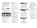
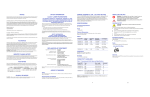
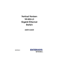
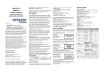
VHIM-2GSX-L3 GIGABIT ETHERNET EXPANSION MODULE QUICK INSTALLATION GUIDE 9033694-01 NOTICE! ONLY QUALIFIED PERSONNEL SHOULD PERFORM INSTALLATION PROCEDURES. Enterasys Networks reserves the right to make changes in specifications and other information contained in this document without prior notice. The reader should in all cases consult Enterasys Networks to determine whether any such changes have been made. The hardware, firmware, or software described in this manual is subject to change without notice. IN NO EVENT SHALL ENTERASYS NETWORKS BE LIABLE FOR ANY INCIDENTAL, INDIRECT, SPECIAL, OR CONSEQUENTIAL DAMAGES WHATSOEVER (INCLUDING BUT NOT LIMITED TO LOST PROFITS) ARISING OUT OF OR RELATED TO THIS DOCUMENT, WEB SITE, OR THE INFORMATION CONTAINED IN THEM, EVEN IF ENTERASYS NETWORKS HAS BEEN ADVISED OF, KNEW OF, OR SHOULD HAVE KNOWN OF, THE POSSIBILITY OF SUCH DAMAGES. Enterasys Networks, Inc. 500 Spaulding Turnpike Portsmouth, NH 03801 2002 Enterasys Networks, Inc. All Rights Reserved Printed in the United States of America Order Number: 9033694-01 April 2002 LANVIEW is a registered trademark of Enterasys Networks. ENTERASYS NETWORKS, NETSIGHT, MATRIX, WEBVIEW, and any logos associated therewith, are trademarks of Enterasys Networks. SPECTRUM is a registered trademark of Aprisma Management Technologies, Inc. All other product names mentioned in this manual may be trademarks or registered trademarks of their respective companies. FCC NOTICE This equipment has been tested and found to comply with the limits for a Class A digital device, pursuant to Part 15 of the FCC Rules. These limits are designed to provide reasonable protection against harmful interference when the equipment is operated in a commercial environment. This equipment generates, uses, and can radiate radio frequency energy and, if not installed and used in accordance with this user’s guide, may cause harmful interference to radio communications. Operation of this equipment in a residential area is likely to cause harmful interference in which case the user will be required to correct the interference at his own expense. This device complies with part 15 of the FCC Rules. Operation is subject to the following two conditions: (1) This device may not cause harmful interference, and (2) this device must accept any interference received, including interference that may cause undesired operation. Class A ITE Notice WARNING: This is a class A product. In a domestic environment this product may cause radio interference in which case the user may be required to take adequate measures. EC CONFORMANCE DECLARATION European contact: Enterasys Networks Ltd. Nexus House, Newbury Business Park London Road, Newbury Berkshire RG14 2PZ, England This information technology product complies with ISO/IEC Guide 22 and EN45014. It conforms to the following specifications: EN55022(1988)/CISPR-22(1985) Class A EN50082-1: IEC 1000-4-2, 3, 4, 6 This information technology product complies with the requirements of the Low Voltage Directive 73/23/EEC and the EMC Directive 89/336/ EEC and carries the CE Mark accordingly. SAFETY WARNING Before installing or removing the VHIM-2GBC-L3, first disconnect the switch from the main power supply. For full safety instructions, please refer to the user guide that accompanies the switch. WARNING: Changes or modifications made to this device which are not expressly approved by the party responsible for compliance could void the user’s authority to operate the equipment. Warning: INDUSTRY CANADA NOTICE When using a fiber optic media expansion module, never look at the transmit laser while it is powered on. Also, never look directly at the fiber TX port and fiber cable ends when they are powered on. This digital apparatus does not exceed the Class A limits for radio noise emissions from digital apparatus set out in the Radio Interference Regulations of the Canadian Department of Communications. Le présent appareil numérique n’émet pas de bruits radioélectriques dépassant les limites applicables aux appareils numériques de la class A prescrites dans le Optical Safety for Fiber Optic Modules CLASS I LASER DEVICE SPECIFICATIONS Ports 2 1000Base-SX Communication Mode Full duplex mode and flow control Network Interface SC connector, 850 nm short-wavelength transceiver 62.5/125 or 50/125 micron multimode fiber cable Switch Method Store-and-forward Queue Buffer 16 Mbytes Size 4.82 x 3.57 x 1.08 in. (12.25 x 90.70.5 x 2.74 cm) Power Consumption 2.4W maximum Temperature Operating: 32° to 131° F (0° to 55° C) Storage: -40° to 131° F (-25° to 55° C) Humidity Operating: 5% to 95% Emissions FCC Class A, VCCI class A, BSMI class A EN55022 Class A, C-Tick class A, CE Mark Immunity IEC 1000-4-2/3/4/6 Standards IEEE 802.3z Gigabit Ethernet ISO/IEC 8802-3 CABLE TYPES AND SPECIFICATIONS Cable 10Base-T Type Cat. 3,4,5 100-ohm UTP Max. Length 100 m (328 ft.) 100 m (328 ft.) 100 m (328 ft.) Connector RJ-45 RJ-45 100Base-T Cat. 5 100-ohm 1000Base-T Cat. 5e 100-ohm 1000Base-SX 50/125 µm or 62.5/125 µm multimode fiber See table below SC or ST MMF or SMF See table below SC or ST 1000Base-LX RJ-45 1000Base-SX Fiber Avertissment: Règlement sur le brouillage radioélectrique édicté par le ministère des Communications du Canada. DISPOSITIF Ports pour fibres LASER DE optiques –sécurité sur le CLASSE I plan optique Ne regardez jamais le laser tant qu'il est sous tension. Ne regardez jamais directement le port TX (Transmission) à fibres optiques et les embouts de câbles à fibres optiques tant qu'ils sont sous tension. VCCI NOTICE Warnhinweis: Faseroptikanschlüsse – Optische Sicherheit Niemals direkt auf den Faser-TX-Anschluß und auf die Faserkabelenden schauen, während diese eingeschaltet sind. LASERGERÄT DER KLASSE I Niemals ein Übertragungslaser betrachten, während dieses eingeschaltet ist. Diameter 62.5/125 µm MMF 50/125 µm MMF Bandwidth 160 MHz/km 200 MHz/km 400 MHz/km 500 MHz/km Range 2-220 m (7-722 ft.) 2-275 m (7-902 ft.) 2-500 m (7-1641 ft.) 2-550 m (7-1805 ft.) 1000Base-LX Fiber Diameter 9 µm SMF Bandwidth N/A Range 2 m – 5 km (16,404 ft.) 62.5/125 µm MMF 500 MHz/km 2-550 m (7-1805 ft.) 50/125 µm MMF 400 MHz/km 500 MHz/km 2-550 m (7-1805 ft.) 2-550 m (7-1805 ft.) Note: Network diameter is defined as the wire distance between two end stations in the same collision domain. VERTICAL HORIZON FAST ETHERNET SWITCH 1000BASE-SX GIGABIT ETHERNET EXPANSION MODULE Enterasys’s VHIM-2GSX-L3 1000Base-SX Gigabit Ethernet Expansion Module provides two shortwavelength (850 nm) Gigabit ports that can be used for a high-speed backbone or server connections. It contains two 1000Base-SX ports that can be connected to a site up to 550 m (1805 ft) away with fiber cable. CAUTION: The VHIM-2GSX-L3 Expansion Module can easily be damaged by electrostatic discharge. To prevent electrostatic damage, observe the following guidelines: • Do not remove the module from its packaging until you are ready to install it. • Do not touch any of the module’s pins, connectors or components. • Hold the module only by its edges or front panel. • Wear an anti-static wristband connected to a suitable earth ground whenever handling the module. Gigabit Port LEDs Gigabit port LEDs are located on the front panel of the module, to the left of the represented port. These LEDs provide port status for “at-a-glance” network monitoring. The following table details the indicator functions provided by the VHIM-2GSX-L3: LEDs Link Act Expansion Module LEDs Condition Status Steady Green A valid link has been established on the port. Flashing Traffic is passing through the port. INSTALLING THE MODULE CAUTION: The VHIM-2GSX-L3 module is designed for the VH-2402-L3 switch only. Do not try to install this module in any other units. The VHIM-2GSX-L3 Expansion Module installs in the expansion slot on the front panel of the VH-2402-L3 switch. To install the module, follow the instructions below. Equipment Checklist After unpacking the VHIM-2GXS-L3 Expansion Module, check the contents of the box to be sure you’ve received the following items: • One VHIM-2GSX-L3 Expansion Module • This document the fiber port to ensure that they are operating correctly. Refer to the table of LEDs in this guide for a description of the LED indications. If the module does not respond, see “Troubleshooting” below. Handling the Module 5. Insert the new module into the switch: Holding the new module with the text on the front panel upright, carefully slide the module into the switch slot and press gently until it snaps into place. Be sure the new module’s front panel is flush with the switch panel. • Store or transport this module only in appropriate anti-static packaging. 3. Loosen the screws on the installed module or slot faceplate: Using your fingers or a flat head screwdriver, turn the screws securing the module (or faceplate on the slot) in a counter-clockwise direction until they are free of the chassis. Be sure not to completely remove the screws from the module or faceplate. • Ensure that the module is properly seated in the slot. 6. Secure the new module: Secure the new module in place by screwing the attached screws clockwise into the switch’s chassis. Tighten them enough to secure the module, but not so tight as to prevent them from being unscrewed by hand. 7. Connect the network cable: Connect fiber cable to the port on the newly installed module. See “Connectivity Guidelines” in this guide for further information. 4. Remove the installed module or faceplate: Firmly pull on the screws until the module is free of the switch. Carefully slide the module straight out of the slot. Keep the original faceplate for future use. If you should remove the module, replace the faceplate to prevent dust and debris from entering the unit and to maintain proper air flow. If you experience any problems with the module, check the following items before contacting Enterasys’s Technical Support: • Ensure that the device attached to the module is powered up and operating correctly. CAUTION: The switch must be powered off before installing or replacing any module. 2. Remove network cables: If you are replacing a module, remove the cable attached to the port on the module. TROUBLESHOOTING • Ensure the VH-2402-L3 switch with the Gigabit Expansion Module is powered up. Instructions 1. Power off the switch: Disconnect the AC power cord from the switch. If a redundant power unit (RPU) is present, disconnect its DC cable connection to the switch. More details concerning connection options and network applications can be found in the VH2402S Installation Guide. Information on the module’s configuration options can be found in the Management Guide that is included with the base unit. 8. Power on the switch: Reconnect the previously removed power sources to the switch. The switch’s front-panel LEDs should indicate the status of the new connection. Check the LED indicators for • Verify that the attached device is configured to match the communication mode used by the module (1 Gbps, full duplex). • Check the connectors on both ends of the cable to be sure they are properly engaged. When attaching fiber cable to an SC-type port, be sure the plug clicks into place to ensure that it is properly seated. • Be sure the fiber terminators are clean. You can clean the cable plugs by wiping them gently with a clean tissue or cotton ball moistened with a little ethanol. Dirty fiber terminators on fiber optic cables will impair the quality of the light transmitted through the cable.