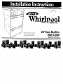
1
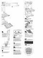
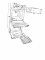
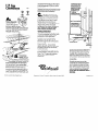
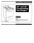
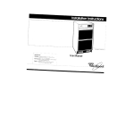
Home .*’r% Appliances
Note: Installer: Leave lnstallot~on
Instructions with the homeowner
Homeowner: Keep Installation
Instructions for future reference
24”Gas Built-in
Wall Oven
Blanket of Flame
Before you start...
Proper installation
IS your responsibllit$
Make sure you have everything
necessary
for COrreCt installation.
It IS the responsibility
of the Installer to comply
with the instollatlon
clearance
specified
on the serloliratlng
plate
The serlalirailng
plate can be
found on tt \e oven frame behlnd
the
upper ovefl
are for wall oven sitiing 6n
cabinet
floor. Cabinet
floor must
be solid and level.
wall gas line
opening - 71
max. len IrOn
~nlerolcabi”
35%” from
abInd
bO”cw
--
-
I-----
’
22’op%nl”g
\
24’
cabinet
depth
Note Clearances
specified
are for combustible
walls and
moterlals
that hove o density of
adjacent
to materlals
that
are less than 20 pounds
per cu fi or to plastic tiles
and sheeting
FOR YOUR SAFETY
If you smell gas:
1. Open windows.
2. Don’t touch electrical switches
3. Extinguish any open flame.
4. Immediately call your gas
supplier.
1FOR YOUR SAFETY 1
Do not store or use gasoline
or other flammable vapors and
liquids in the vicinity of this
or any other appliance.
1FOR YOUR SAFETY 1
Do not obstruct the flow of
combustion and ventilation air.
--‘---1
‘\
\\-
ALL OPENINGS
IN THE WALL
OR FLOOR WHERE THE
WALL OVEN IS TO BE INSTALLED
MUST BE SEALED
1
/I
0
B-
--0
I
I
I
I
I
I
I
I
I
I
I
t-----
Check location
where wall oven
WIII be Installed.
The locatIon
should be away
from strong draft
arem.
such as windows,
doors,
and strong heating
vents or fans
The wall oven should be
located
for convenient
use
in the kitchen
1FOR YOUR SAFETY 1
wldlh
Back or oven
helghl-3,W
‘\
Important: Observe all governlng
codes ond ordlnonces. Fallure lo meet
boltom
from floor
codes and ordinances
fire or elecklcal
shock
Mobile
If ovens
Grounded
electrical
outlet:
See Electrical
Requirements.
Proper gas supply
connection
available.
See Gas Supply
Requirements.
Tools needed
must be
for installation.
hove
outside
The recesses
rnstallatlon
area must
provide
complete
enclosure
around
the
recessed
portion of the oven
C
This wall
pipe with 4” Inside
diameter
and 6” outside
diameter
must be used
oven
is equipped
for
aas. It IS
certified
by A.G.A. for NATURAL and L.P
gases with appropriate
conversion.
The
seriol/ratlng
plate located
on the oven
frame behind
the broiler door has
information
on the type of gas that can
be used. If this information
does not
agree with the type of gas available,
check with the local gas suppller
See
Backcover
for L.P gas conversIon
instructions.
n use with NATURAL
lead
to
Home Installation
The installation
of this range must
conform
to the Manufactured
Home
Construction
and Safety Standards.
Title
24 CFR. Port 32-80 [formerly
the Federal
Standard
for Moblle
Home ConstructIon
and Safety. Title 24, HUD [part 28011.
Copies of the standards
may be obtalned
from:
listed
‘American
Gas Assoclallon
1515 Wllson Boulevard
Arflngton.Vlrglnlo
22209
“NatIonal
Fire Prolectlon
Batterymarch
Park
Qulncy,
Massachusetts
Assoclalion
02269
D
Gas Supply
Requirements
Observe all governing
and ordinances.
must
IS required
could
hazard.
codes
A
This instollatlon
must conform
n with local codes and
ordinances.
In the absence
of local
codes, installation
must conform
with
American
National
Standard,
National
Fuel Gas Code ANSI 2223 l-1984’
Provide a gas supply line of
n “8 rlcld pipe to the wall oven
location
eltherthrd6gh
the wall or
cabinet
floor. Keep pipe near the wall.
The wall oven gas flttlng is located
at
upper right side of appliance.
Pipe joint
compounds
resistant to the action of L.P
gas must be used With L.P gas. piplng
or
tubing
sfze can be ‘/2” minimum.
L.P aas
suppliers
usually determine
the size&d
materials
used on their system
E
If local codes permit, A.G A
n cetiifled flexible metal tubing
(new] IS recommended
for connecting
this wall oven to the gas supply IIne. Do
Not kink or damage
the flexible tubing
when moving
the wall oven AK” male
pipe thread
IS needed
for connectIon
to
pressure regulator
female
pipe threads
G
n
pipe finin
in-line connectton
to fhe wall oven. All
strains must be removed
from the supply
and fuel lines so wall oven will be level
and in line
H
The Inlet pressure to the
w regulator
should be CIS follows
for both operation
and checking
regulator
senlng
NATURAL
Minimum
Maximum
L.P GAS;
Minimum
Maximum
GAS:
pressure
pressure
5 inches
14 inches
pressure
pressure
11 inches
14 inches
I
serioliratlng
plate are for
elevations
up to 2,000 feet For
elevdtions
above
2,000 feet, ratings
should be reduced
at a rate of 4% for
each 1,000 feet above
sea level.
PANEL
A
This valve should be located
in the same
room OS the wall oven and should be in
a location
that allows ease of opening
and closing.
Do Not block access to
shut-off valve
This wall oven
burner shut-oft
oven manifold.
is equipped
with an oven
valve located
on the wall
The wall oven and its indlvlduol
n shut-off valve must be
disconnected
from the gas supply
plping system during any pressure
testing of that system at test pressures
in excess of K psig (3.5 kPo].
The wall oven must be isolated
from the
gas supply piping
system by closing Its
lndlvidual
manual
shut-off valve during
any pressure testing of the gas supply
piping system at test pressures equal to
or less than ‘/2 psig (3.5 kPa)
Electrical
Requirements
Now Start...
With wall oven in kitchen.
Warnlng:
Improper
connection
of the
equipment
grounding
conductor
can
result in a risk of electrical
shock.
1
Remove
racks
and
other
parts
n from inside oven
A 120 Volt. 60 Hr. AC only. 15 Ampere
fused electrlcal
supply IS reqwed
[tlme-delay
fuse or clrcult breaker
IS
recommended]
It IS recommended
that
a separate
clrcult sewing only this
appliance
be provided
DO NOT USE AN
EXTENSION CORD.
A wrung diagram
IS Included
in Merature
package.
The wiring diagram
1s also
located
behlnd
the control panel
2
Remove shipping
materials.
n tape and protective
film from
wall oven. Do Not remove cardboard
ShippIng
base at this lime
Recommended
Grounding
Method
DO NOT, UNDER ANY CIRCUMSTANCES,
REMOVE THE POWER SUPPLY CORD
GROUNDING
PRONG.
For your personal
safety, this appliance
must be grounded
This appliance
IS
equipped
with a power supply cord
haVlnQ 0 3-piO”Q
grounding
PfUQ To
mln~mlze possible shock hazard.
the
cord must be plugged
Into a mating
3prong Qroundlng
type wall receptacle,
grounded
I” accordance
with the
National
Electrical
Code. ANSliNFPA
70-1984 ++ and local codes and
ordinances
See Figure 1 If a mating
wall
ECeDtaCle
is not available
It IS the
PerSOnal
responslblllty
and
obllgationofihe
customer
Temporary
Remove the
oven control
knob Remove
the 2 screws that
attach
the control panel to the oven
frame
Move the control
panel down
and forward
Disconnect
the plug from
the terminal
block. Carefully
place
control panel. screws and oven control
knob in a safe location.
.
Grounding Method
6
Assemble
the flwble
connector
n from the Qas supply pipe in this
order: manual
shut-off valve, K” nipple,
%” adaDter.
flexlbie connector.
W’
adapt&
and K” nipple
tiNOr,
UNDER ANY CIRCUMSTANCES,
REMOVE THE POWER SUPPLY CORD
GROUNDING
PRONG.
Flexible
connector
If oven WI// be vented outsIde, remove
the flue cover and collar cap See backcover for Venting
lnstallat~on
Instructions.
Manual
shut-ofl
valve
r
CPowell”PPlY
Electrical
ground
Is required
on this
appliance
If changing
and properly
grounding
ihe wall receptacle
IS impossible
and
where local codes permit (consult vour
elecfrical
inspecfor].
a tetiporary
adODtOr rnav be oluaaed
Into the
existing 2-p&Q
~all~&eptacle
to mate
with the &prong
power supply cord.
PANEL B
YI” adapter
WARNING:
THE REGULATOR IS DIE CAST
IF THE CONNECTION
IS MADE TOO
TIGHT, IT WILL CRACK RESULTING IN A
GAS LEAK AND POSSIBLE FIRE OR
EXPLOSION.
cora
If this is done, you must connect
a
separate
copper
QrOUndlnQ we (No. 18
mInImum)
lo a grounded
cold water
pipe by means of a clamp
and then to
the exiernal
grounding
connector
screw
Uo nol ground
10 a gas supply
pipe,
Do not connect
to electrical
supply
until appliance
IS permanently
grounded
See Figure 2.
Grounded
cold water pipe must
have metal continuity
to electrlcai
ground
and not be interrupted
by plastic.
rubber or other electrical
insulating
connectors
such as
Yz” adapter
5w
Open door to first stop posItIon
and lift door upward
and off hInQeS
7
Lift wall oven up to cabinet
cutoul. using the oven opening
W
as an area to grip. Thread flexible
connector
through
back of wall oven
Plug the electrical
cord Into the
grounded
outlet
Discard
cardboard
shlpping
piece
or wall
Rynnn,r+
Move oven into cabinet
cutout and center, Check
that spacers behind
front
frame are trght against
the front of the cabinet.
Do
Not recess the spacers
The small gap provided
by spacers allows air flow
for cooling
the cabinet.
10
Disconnect
shut-off valve line
n by removrng the flared nut
Remove two screws that attach
the
manifold
pipe and regulator
to the
mountrng
bracket
Move regulator
skghtly and attach
flexible conneciorio
pressure regulator
Reconnect
marxfold
pipe to mountrng
bracket.
Reconnect
shut-off valve.
No adjustment
of the oven
H
burner is necessary.
The hazy
appearance
of the flame IS normal
for
this type of burner.
Use pope jornt compound
n resistant to the action of
L P gas to seal all gas connectIons
If
flexible connectors
are used, be certain
connectors
are not krnked. Check that
the oven shut-off valve IS open
13
If oven ~111 be vented outsrde.
the vent system. See backcover
Venting
Installation
instructions
PANEL C
connect
for
\.,,r~
17
11
minutes
line
to
Push rn and turni,
’
the oven control
knob to,
m
“300”F’The
oven burner should light rn 50
to 60 seconds. This delay IS normal
The
oven safety valve requires a certain
time
before it will open and allow gas to flow.
:;:,
12
oven
ia
.
Replace
oven door
by sliding the door over
hinge arms
Open the shut-off valve rn the
n gas supply line Wait a few
for gas to move through
the gas
Use a brush and liquid
n detergent
to test 011 gas
connectrons
for leaks. Bubbles around
connectrons
wrll Indicate
a leak If a
leak appears,
shut off gas valve controls
and adjust connections.
Then check
connectrons
agarn.
NEVER TEST FOR GAS
LEAKS WITH A MATCH OR OTHER FLAME.
Clean all detergent
solution from warI
oven.
(
Congratulations!
\
\
lnstru~llo~
and Guide close lo wall
oven for easy reference.
The
InstructIons
will make re-InstallIng
your WhIrlpool wall we” In
another home as easy as
the tlrst Installation.
1
and place the Natural gas orifice spud
in the compartment. Put the L.P orifice
spud in place.
Replace the burner so the screen louvers
face the rear of oven. No gas input or air
shutter adjustment is necessan/.
L.?! Gas
Conversion
Natural
Cablnel
mrtombte
back must be
horn hunt.
C
After the burner has been
W converted to L.P aas usaae
and gas line is connectedycheckyor
leaks. Use a brush and liquid detergenl
to test all gas connections for leaks.
Bubbles around connections will
indicate a leak. If a leak appears, shut
off gas valve controls and adjust
connections. Then check connections
again. NEVER TESTFOR GAS LEAKS
WITH A MATCH OR OTHER FLAME.
A.
Pressure Regulator:
Use a wrench to
unscrew the cap from
the top by turning counte
clockwise Turn the cap over so the hole
end is up. Replace the cap and gasket
on the regulator. DO NOT REMOVE THE
PRESSUREREGULATOR. ,,
Venting Installation
This oven is equipped with either inside
or optional outside venting. Follow
instructions for your application.
Inside Venting-no
adjustments are
necessary, oven will vent into the
kitchen through the vent in the control
panel housing.
Outside Venting-To use outside
venting, the flue collar cap and cover
(located under the top heat shield]
must be removed.
When outside stack venting (Method
#t. see illustration] is required, use only
Class “A” or “B” approved materials
Venting must conform to local
ordinances.
1 Flame Broiler
b Burner: Remove
1 the oven burner
-by
pressing in on front of burner
until retainer clips loosen. Gently pull
burner out and down until orifice spud
can be reached. Care must be taken
not to break the ignitor coil. Carefully put
the burner aside so screen side is up,
Remove the burner orifice spud, using a
5/i/’ wrench. Take the LF! orifice spud out
of the compartment on the left oven wall
Part No 36.C!61039-02-O/78680
Rev
A
Prepared
by WhQxxl
Corporation.
Benton
Harbor,
Michlgon
F oven unii
(not to floor)
1
For rear wall connection [Method #2,
see illustration) provide a Class “B:‘4”
I.D. opening at the center line of the
cabinet cut out. The height of the
opening is determined by the height
of the unit from the floor and the face
to center dimensions of the stack
connections.
The wall oven vent may not be
connected into a ventilation system
which already provides discharge
from another household appliance.
Note: The centerline of the flue pipe
and the cabinet must be aligned.
OUTLET MUST BETERMINATED ABOVE
ROOFLINE.
49022
Printed
I” US A