1
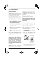
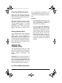
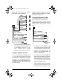
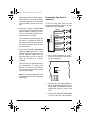
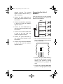
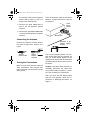
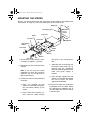
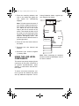
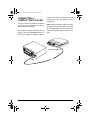
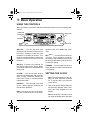
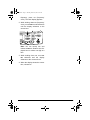
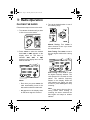
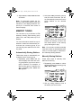
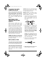
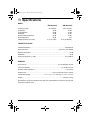
12-2130.fm Page 1 Thursday, March 16, 2000 8:12 AM
Please read before using this equipment.
AM/FM Cassette Car Stereo
with 22 Watts X 2 Max Power
Owner’s Manual
12-2130.fm Page 2 Thursday, March 16, 2000 8:12 AM
ˆ Contents
Features .................................................................................................................................. 3
Installation .............................................................................................................................. 5
Preparation ....................................................................................................................... 5
Setting the Shaft Spacing .......................................................................................... 5
Preparing the Mounting Area ..................................................................................... 6
Routing Speaker Wires .............................................................................................. 6
Making the Connections .................................................................................................... 6
Using an Adapter Harness ......................................................................................... 7
Connecting Ground, Power, and Optional Components ............................................ 7
Connecting Two Pairs of Speakers ............................................................................ 8
Connecting One Pair of Speakers ............................................................................. 9
Connecting the Antenna .......................................................................................... 10
Testing the Connections .......................................................................................... 10
Mounting the Stereo ........................................................................................................ 11
Using the Line Level Components .................................................................................. 12
Connecting a Compact Disc Player ................................................................................ 13
Basic Operation .................................................................................................................... 14
Using the Controls ........................................................................................................... 14
Setting the Clock ............................................................................................................. 14
Radio Operation ...................................................................................................................
Playing the Radio ............................................................................................................
Memory Tuning ...............................................................................................................
Automatically Storing Stations .................................................................................
Manually Storing Stations ........................................................................................
Storing Stations in Automatic Travel Programming Memory ...................................
Selecting a Stored Station .......................................................................................
Scanning Stored Stations ........................................................................................
16
16
17
17
17
18
18
18
Cassette Player Operation ...................................................................................................
Playing a Cassette ..........................................................................................................
Fast-Forward and Rewind ........................................................................................
Listening to the Radio During Fast-Forward or Rewind ...........................................
19
19
20
20
Care and Maintenance .........................................................................................................
The FCC Wants You To Know .........................................................................................
Cleaning the Tape-Handling Parts ..................................................................................
Restoring Tape Tension and Sound Quality ....................................................................
Replacing a Fuse ............................................................................................................
21
21
22
22
22
Specifications ....................................................................................................................... 23
© 1998, 1999, 2000 Tandy Corporation.
All Rights Reserved.
RadioShack is a registered trademark used by Tandy Corporation.
RadioShack.com is a trademark used by Tandy Corporation.
2
Contents
12-2130.fm Page 3 Thursday, March 16, 2000 8:12 AM
ˆ Features
Your RadioShack AM/FM Cassette Car
Stereo has many practical, easy-to-use
features, and you can install it in almost
any vehicle. The stereo’s CD input jack
lets you connect any portable CD player
with a DC adapter. The tuner’s digital
synthesized PLL (phase-locked-loop)
circuitry gives you precise tuning and
drift-free reception.
Balance, tone, fader and volume controls let you adjust the sound for maximum listening pleasure.
Radio Monitor — lets you hear the radio while you fast forward or rewind a
cassette tape.
Preamp Outputs — let you connect an
optional equalizer/booster with phono
plugs.
Lighted Display with Clock — lets you
easily see the clock, radio, and cassette
deck function selections.
The stereo’s features include:
Scan Tuning — scans forward on the
selected band, stopping for several seconds on each station.
CD Input Jack — lets you easily connect a portable compact disc (CD) player.
Seek Tuning — searches forward to
the next strong station in the selected
band.
Continuous Auto-Reverse — allows
continuous play of both sides of a cassette tape.
Automatic Seek and Scan Sensitivity
— adjusts your stereo so the first time it
searches a band it stops only on strong
local stations, and the next time it
searches it also stops on weaker distant
stations.
High Power — provides 32 watts of total power to give you excellent audio response for all types of music.
Manual/Automatic Memory Programming — lets you manually or automatically store six AM and 12 FM stations
into memory so you can quickly tune to
those stations with the press of a button.
Automatic Travel Programming —
lets you store an additional six AM stations and six FM stations separate from
the manual/automatic programmed
memory groups.
Line-Level Outputs — let you connect
the stereo to external power amplifiers,
boosters, or other accessories that have
line input jacks.
Balance Control — lets you balance
the sound between your left and right
speakers.
Locking Fast-Forward/Reverse — lets
you quickly move the tape to either the
beginning or the end without holding the
fast-forward button.
Features
3
12-2130.fm Page 4 Thursday, March 16, 2000 8:12 AM
Advanced FM Optimizer Circuitry —
automatically adjusts the tuner’s stereo
separation and high-frequency response
to give you the best possible sound, regardless of the signal level.
Push Band Selector — lets you easily
select AM or FM stations with the push
of a button.
Adjustable Shaft Spacing — fits almost all shaft type installations.
Built-In Loudness Circuitry — automatically boosts your stereo’s high and
low frequencies for better sound at low
volume levels.
4
Features
12-2130.fm Page 5 Thursday, March 16, 2000 8:12 AM
ˆ Installation
PREPARATION
Caution: Improper installation can damage your stereo and other components in
your vehicle’s autosound system.
Before you install your stereo, read all
the instructions in this owner’s manual.
You should be able to answer all of
these questions about your vehicle’s
electrical and sound systems:
• Does my vehicle have a 12-volt negative ground electrical system?
channel). Each speaker must have an
impedance of at least 4 ohms. Your local RadioShack store carries a full line
of speakers.
Setting the Shaft Spacing
The size of existing openings in the
dash or installation kit determines the
best spacing between the stereo’s
shafts (knobs).
• Which terminal in my vehicle’s fuse
box supplies power even when the
ignition is turned off?
The space between the shafts is preset
to 513/16 inches (148 mm) at the factory.
You can change the spacing to 55/8
inches (142 mm), to 53/8 inches (136
mm), or to 51/8 inches (130 mm).
• Which terminal in my vehicle’s fuse
box is for accessories?
Follow these steps if you need to
change the shaft spacing.
• How do I connect a wire to the fuse
box?
1. Loosen each shaft nut about halfway up the shaft.
Also, be aware that installation in your
vehicle might require cutting or modifying your vehicle.
2. Move each shaft positioner to the
correct pair of holes, as shown.
Place the stereo as close as possible to
the selected mounting location. We recommend that you install the stereo by
temporarily connecting it to ground and
power, optional components, and your
speakers. Then test the connections.
Next, disconnect the stereo, mount it in
your vehicle, and then reconnect it. The
instructions in this manual are arranged
in this order.
Caution: Be sure your speakers can
handle 32 watts of power (16 watts per
51/8
513/16
53/8
55/8
3. Hold each shaft positioner in place
as you re-tighten its shaft nut.
Installation
5
12-2130.fm Page 6 Thursday, March 16, 2000 8:12 AM
Preparing the Mounting Area
Before you mount the stereo, make sure
you have all the necessary materials.
Then confirm that the stereo fits your vehicle’s mounting area.
Note: If the mounting area is too large,
you might be able to mount the stereo
with the supplied gasket or an in-dash
installation kit, available at your local
RadioShack store. Follow the installation kit’s instructions to mount the stereo.
Routing Speaker Wires
If you install speakers, avoid routing the
speaker wires near moving parts or
sharp edges. You can usually route
wires along the channel beneath the vehicle’s door facings by carefully removing the molding that holds the carpet in
place. After you route the speaker wires,
replace the molding.
tem, to complete the connections. Your
local RadioShack store carries a full line
of wire and wire management accessories.
Cautions:
• For added safety and to protect your
stereo, disconnect the cable from
your vehicle battery’s negative (–)
terminal before you begin.
• You must connect the GROUND (–),
+12V TO IGNITION, and +12V TO BATTERY wires first, then make all other
connections as described in the following sections before you plug the
wire harness with the 14-pin connector into the stereo. If any wire
connections are made incorrectly or
out of order shown in the following
illustration, damage to the stereo is
possible.
MAKING THE
CONNECTIONS
The supplied harness with the 14-pin
connector includes all the lead wires you
need to connect the stereo to ground,
power, optional components, and
speakers.
Important: Do not cut the lead wires. If
you cut any wire, you cannot obtain a refund or exchange on this product. However, your local RadioShack store will
provide warranty service if you cut a
wire and find the product is defective.
You might need additional wire, depending on your individual autosound sys6
Installation
12-2130.fm Page 7 Thursday, March 16, 2000 8:12 AM
Note: The wires in the wire harness
have these colors and labels.
(White)
Speaker Wires
(White/Black)
FRONT LEFT
Wire
Harness
Follow the directions that come with the
adapter harness to temporarily connect
the power and speakers.
Connecting Ground, Power,
and Optional Components
(Gray)
Follow these steps to connect the wire
harness to ground, primary and memory
backup power, and optional components.
(Gray/Black)
FRONT RIGHT
(Green)
(Green/Black)
REAR LEFT
(Violet)
(Violet/Black)
REAR RIGHT
Black
Red
Black
GROUND (–)
Red
+12V to IGNITION
GROUND (–)
+12V to IGNITION
Blue/White
Blue/White
AMP REMOTE
AMP REMOTE
Yellow +12V to BATTERY
Yellow +12V to BATTERY
In-Line Fuse
Holder
• You must connect a separate wire to
each speaker terminal as described
in the following procedure. Do not
use a common wire or chassis
ground for any speaker connection.
Using an Adapter Harness
If you are replacing an existing stereo,
or if your vehicle has been factory-wired
for autosound components, you might
be able to use an adapter harness to
connect the power and speakers. RadioShack stores sell adapter harnesses
for most vehicles.
1. Connect the black GROUND (–) wire
to a chassis ground, such as a metal
screw attached to a metal part of the
vehicle’s frame. Be sure that the
screw is not insulated from the
frame by a plastic part.
2. Connect the red +12V to IGNITION wire
(with in-line fuse holder) to a point in
your vehicle’s fuse block that has
power only when you turn the vehicle’s key to either the accessory
(ACC) or START position.
Installation
This connection turns on the stereo
when you turn on the ignition or turn
the key to ACC, and turns off the
7
12-2130.fm Page 8 Thursday, March 16, 2000 8:12 AM
3. Connect the yellow +12V to BATTERY
wire (with in-line fuse holder) to your
vehicle battery’s positive (+) terminal or to a fuse that provides a continuous source of 12 volts.
Connecting Two Pairs of
Speakers
If you are using both front and rear
speakers, follow these steps to connect
the harness to the speakers.
(White)
(White/Black)
FRONT LEFT
Speaker Wires
stereo when you turn off the ignition.
This prevents your vehicle’s battery
from being drained if you leave the
stereo on when you turn off the ignition.
This connection provides power for
the stereo’s components (such as
the clock), and continuous power for
the stereo’s memory when the ignition is turned off.
4. Connect the blue/white AMP REMOTE
TURN ON 500MA MAX wire to any
optional equipment designed to run
from a switched source that you
want the stereo to turn on and off
(such as a booster or a power
antenna).
(Gray)
(Gray/Black)
FRONT RIGHT
(Green)
(Green/Black)
REAR LEFT
(Violet)
(Violet/Black)
REAR RIGHT
1. Use a small screwdriver to move 2
ch 4ch on the bottom of the stereo to
4 ch (four channels).
This wire does not provide power to
the components. It simply turns
them on or off. If you do not use this
wire, secure it with a wire tie and do
not let it touch metal.
2ch
4ch
Note: The optional equipment must
be designed for use with a switched
power lead.
2. Connect the gray FRONT RIGHT (+)
wire to the front right speaker’s positive terminal. The terminal is usually
marked with a plus (+) sign or red
mark.
3. Connect the gray/black FRONT RIGHT
(–) wire to the front right speaker’s
8
Installation
12-2130.fm Page 9 Thursday, March 16, 2000 8:12 AM
negative terminal. This terminal
might be marked with a minus (–)
sign or unmarked.
4. Connect the white FRONT LEFT (+)
wire to the front left speaker’s positive terminal.
Connecting One Pair of
Speakers
If you are using only one pair of speakers, follow these steps to connect the
harness to the speakers.
(White)
5. Connect the white/black FRONT LEFT
(–) wire to the front left speaker’s
negative terminal.
Speaker Wires
FRONT LEFT
6. Connect the violet REAR RIGHT (+)
wire to the right rear speaker’s positive terminal.
7. Connect the violet/black REAR RIGHT
(–) wire to the rear right rear
speaker’s negative terminal.
8. Connect the green REAR LEFT (+)
wire to the rear left speaker’s positive terminal.
9. Connect the green/black REAR LEFT
(–) wire to the rear left speaker’s
negative terminal.
(Gray)
FRONT RIGHT
(Green/Black)
REAR LEFT
(Violet/Black)
REAR RIGHT
1. Use a small screwdriver to move 2
ch 4 ch on the bottom of the stereo to
2 ch (two channels).
2ch
4ch
2. Connect the gray FRONT RIGHT (+)
wire to the right speaker’s positive
terminal. This terminal is usually
marked with a plus (+) sign or red
mark.
3. Connect the violet/black REAR RIGHT
(–) wire to the right speaker’s nega-
Installation
9
12-2130.fm Page 10 Thursday, March 16, 2000 8:12 AM
tive terminal. This terminal might be
marked with a minus (–) sign or it
might not be marked at all.
Then reconnect the cable to the vehicle
battery’s negative terminal to test the
connections.
14-Pin
Wiring
Socket
4. Connect the white FRONT LEFT (+)
wire to the left speaker’s positive
terminal.
5. Connect the green/black REAR LEFT
(–) wire to the left speaker’s negative
terminal.
Wire Harness
Connecting the Antenna
Reconnect to the
battery’s negative
terminal
Connect the vehicle’s antenna cable to
the stereo’s large black antenna connector.
Vehicle’s
Antenna Cable
Turn on your vehicle’s ignition. The display should light and the currently set
time (or 12:00) should appear on the
display when you turn the left inner shaft
clockwise until you hear it click to turn on
the stereo.
Stereo’s
Antenna
Connector
Testing the Connections
Make sure you have securely made all
other connections, then plug the harness’s connector into the stereo’s 14-pin
wiring socket.
Caution: If the stereo does not work, immediately disconnect the cable from
your vehicle battery’s negative (–) terminal. Then recheck your connections.
After you verify that the display lights
and the clock appears, follow the instructions in “Mounting the Stereo” on
Page 11.
10
Installation
12-2130.fm Page 11 Thursday, March 16, 2000 8:12 AM
MOUNTING THE STEREO
Be sure you test the stereo first and verify that it works properly. (See “Making the
Connections” on Page 6.) Then follow these steps to mount the stereo.
Metal Strap
Self-Tapping Screw
Solid Metal
Part of
Vehicle
Front Panel
Gasket
Nut
Trim Plate
Dashboard
Spring Washer
Shaft Spacing
Adapter
Outer Knob
Nut
Washer
Nut
Washer
Nut
Washer
Inner Knob
1. Disconnect the cable from the vehicle battery’s negative (–) terminal.
the holes in the mounting surface.
2. Disconnect the wire harness and the
antenna.
c. Adjust the nuts on the shafts until
the stereo’s front panel lines up
properly with the dashboard.
Insert the supplied gasket if additional front panel support is
needed.
Note: If you are using an in-dash
installation kit, follow the procedure
outlined in the kit, and proceed to
Step 4 (skip Step 3).
d. Place another supplied nut and
washer on each shaft and tighten
the nuts to secure the stereo
against the dashboard.
3. Position the stereo in the dashboard
as follows:
a. Place one supplied nut and
washer on each shaft and tighten
the nuts about halfway up the
shafts.
b. From behind the mounting surface, insert the shafts through
4. Place the trim plate and shaft-spacing adapters over the shafts. Select
the shaft-spacing adapters that fit
over the shafts and into the cutouts
in the trim plate.
Installation
11
12-2130.fm Page 12 Thursday, March 16, 2000 8:12 AM
5. Place the remaining washers and
nuts on the shafts and tighten the
nuts against the shaft-spacing
adapters.
lowing illustration shows a typical system using the line outputs.
Car Stereo
System
Note: To further secure the stereo, if
your vehicle’s dashboard space permits access to the back of your stereo, attach one end of the metal
strap to the bolt on the back of the
stereo. Then attach the other end of
the strap to a solid metal part of the
vehicle using an existing bolt or the
supplied self-tapping screw. This
strap also ensures that the stereo is
properly grounded.
Preamp
Outputs
Ground
Wire
Optional
Component
Wiring
Wiring
Socket
Socket
6. Place the inner and outer knobs on
the shafts.
7. Reconnect the wire harness and
antenna.
8. Reconnect your vehicle’s negative
(–) battery cable.
Note: When connecting an equalizer/
booster not sold by RadioShack, refer to
its owner’s manual.
USING THE LINE LEVEL
COMPONENTS
This stereo has preamp outputs (phono
connectors) for low-noise connection to
an optional equalizer/booster, power
amplifier, or other device that has linelevel inputs.
To ensure a low-noise connection, connect a ground wire between the stereo
and any additional component. The fol-
12
Installation
12-2130.fm Page 13 Thursday, March 16, 2000 8:12 AM
CONNECTING A
COMPACT DISC PLAYER
You can connect a portable CD player
(or other audio component with a linelevel output) to the stereo.
Use a stereo mini-jack cable with 1/8-inch
plugs. (Your local RadioShack store offers a wide variety of mini-jack cables.)
Connect the cable to CD IN and to the
output jack of the CD player or other
component.
Note: When you plug a cable into CD IN,
you will not be able to listen to the radio
or a cassette tape. Be sure you disconnect the CD player when you are not using it.
CD Player Output Jack
CD IN
Installation
13
12-2130.fm Page 14 Thursday, March 16, 2000 8:12 AM
ˆ Basic Operation
USING THE CONTROLS
When you listen to your stereo, adjust the following controls to suit your listening preferences.
Volume and
On/Off knob
Tuning knob
Tone knob
Balance
knob
(pulled out)
Fader knob
●ON VOL — Turn the left inner knob
clockwise until you hear it click to turn on
the stereo. Continue to turn the knob
clockwise to increase the volume. Turn
the knob counterclockwise to reduce the
sound or until you hear it click to turn off
the stereo.
Warning: To protect your hearing, do
not listen at high volume levels. Slowly
increase the volume to a comfortable listening level.
O TONE — Turn the left outer knob to
adjust for the best treble and bass balance. Turning it clockwise reduces the
bass while turning it counterclockwise
reduces the treble.
FADER O — Turn the right outer knob
for the desired balance between the
front and rear speakers.
Note: If you have only one set of speakers and connected them to the front-
speaker wires, turn
wise.
FADER
fully clock-
BAL ● PULL — Pull the left inner knob until it locks. Turn it clockwise or counterclockwise to adjust balance between the
left and right speakers. Push the knob in
to retain the setting.
TUNING● — Turn the right inner knob in
either direction to select the desired AM
or FM station.
SETTING THE CLOCK
Note: The clock appears on the display even when the stereo is turned
off. To set the clock, you must turn
on the stereo.
1. Turn on the stereo and the radio station frequency appears. After 5 seconds, the clock reappears on the
display.
Note: If the stereo is already on and
you have the display set to the radio
14
Basic Operation
12-2130.fm Page 15 Thursday, March 16, 2000 8:12 AM
frequency, press F/C (frequency/
clock). The clock display appears.
2. While holding down F/C (frequency/
clock), turn TUNING counterclockwise
until the display advances to the
correct hour.
Note: You can quickly turn and
release TUNING to advance the displayed hour or minute one digit at a
time.
3. While holding down F/C, turn TUNING clockwise until the display
advances to the correct minute.
4. When the display shows the correct
time, release F/C.
Basic Operation
15
12-2130.fm Page 16 Thursday, March 16, 2000 8:12 AM
ˆ Radio Operation
PLAYING THE RADIO
3. Tune to the desired station in one of
the following ways:
Follow these steps to listen to the radio.
1. Turn ON VOL clockwise until you hear
it click to turn on the stereo.
Manual Tuning: Turn TUNING in
either direction to tune up or down
the selected band.
2. Press AM/FM to select the desired
band. AM1 or AM2 appears on the
display when an AM band is
selected. FM1, FM2, or FM3
appears on the display when an FM
band is selected.
Notes:
• Each time you press AM/FM, the
radio automatically tunes to the
last station selected in that band.
• ST appears on the display when
an FM stereo signal is received.
16
Seek Tuning: Press SEEK to tune to
the next higher station with a strong
signal.
Scan Tuning: Press SCAN to scan
the higher frequency stations. The
radio pauses for 5 seconds at each
station. The station’s frequency
flashes on the display. When the
radio pauses at a station you want
to listen to, press SCAN again to stop
scanning.
Note: If the stereo does not find a
strong station when seeking or
scanning, the stereo searches the
band again and stops on weaker
stations.
Radio Operation
12-2130.fm Page 17 Thursday, March 16, 2000 8:12 AM
4. Adjust ON VOL, TONE, FADER and BAL
as desired.
Note: To temporarily display the frequency of the current station, press and
release F/C. The display shows the frequency for 5 seconds, then returns to
the time display.
2. Hold down AMS (automatic memory
scan) for about 3 seconds. The stereo automatically stores the first six
strong stations on the selected
band.
MEMORY TUNING
You can store up to six AM and 12 FM
stations in memory. Each memory group
(AM1, FM1, and FM2) holds up to six
stations.
You can let the stereo search for any six
stations in a band and automatically enter these into a memory group, or you
can manually enter stations into a memory group.
Automatically Storing Stations
Follow these steps to automatically enter stations into a memory group.
1. Repeatedly press AM/FM until the
stereo displays the band and memory group where you want to store a
group of stations. For example, to
store the first group of stations into
AM1, repeatedly press AM/FM until
AM1 appears.
After the stereo has stored all six
stations into memory, it tunes to the
first stored station in the memory
group and begins to play.
Note: You can store a station manually
if the stereo does not automatically store
it due to a weak signal or interference.
See “Manually Storing Stations”
Manually Storing Stations
Follow these steps to manually enter
stations into memory.
1. Repeatedly press AM/FM to select
the desired band and memory group
(AM1, FM1 or FM2).
2. Use any tuning method to tune to
the station you want to store.
Radio Operation
17
12-2130.fm Page 18 Thursday, March 16, 2000 8:12 AM
3. Hold down the desired memory
location button (1–6) until the memory location number and the frequency appear on the display. The
volume mutes briefly and the station
is stored.
Selecting a Stored Station
To select a stored station, press AM/
FM to select the desired memory group.
Then press the desired memory location
button.
Storing Stations in Automatic
Travel Programming Memory
The stereo can store the first six strong
AM and the first six strong FM stations it
finds into its automatic travel programming memory (bands AM2 and FM3).
This memory is separate from the stereo’s memory groups, so it does not replace the stations you manually stored.
1. Repeatedly press AM/FM to select
the desired band (AM2 or FM3). The
stereo displays ATP.
2. Hold down AMS for about 2 seconds.
The stereo displays LO, scans the
selected band, and automatically
stores the first six strong stations it
finds in automatic travel programming memory.
After the stereo stores all six stations in the selected band, it tunes to
the first station stored in channel 1.
Notes:
• If the stereo does not find a strong
station with automatic travel programming, the stereo searches the
band again and stops on weaker
stations.
Memory Location Buttons
Note: Do not hold down the memory location button. This erases the previously
stored station and stores the currently
tuned station in its place.
Scanning Stored Stations
The radio can scan all stored stations in
the FM or AM bands, pausing for 5 seconds at each station.
To start scanning stored stations,
press AM/FM to select the band, then
press AMS. The radio begins scanning
the stored stations – AM1 and AM2, or
FM1, FM2 and FM3.
Note: Do not hold down AMS. This causes the radio to automatically seek and
store six stations into the current memory group.
To stop the scanning when the stereo
pauses at a station you want to listen to,
either press AMS or the station’s memory
location button.
• If the stereo could not find any station, the last station tuned to is
recalled.
18
Radio Operation
12-2130.fm Page 19 Thursday, March 16, 2000 8:12 AM
ˆ Cassette Player Operation
PLAYING A CASSETTE
4. Adjust ON VOL, TONE, FADER and BAL
as desired.
Caution: Avoid using C-120 cassette
tapes. They are very thin and can easily become tangled in the tape-handling
parts.
5. Press in
all the way to stop the
tape and eject it.
Follow these steps to play a cassette
tape.
1. Take up any slack by turning the
cassette’s hub with your finger or a
pencil. (Avoid touching the tape.)
Caution: We recommend you
press
as soon as you finish playing a tape or before you leave your
vehicle, to release it from the tapehandling parts. This reduces the
possibility of a tape being inadvertently tangled or damaged.
Notes:
2. Turn ON VOL clockwise until it clicks
to turn on the radio.
3. Put the tape into the cassette compartment with its open edge to the
right and the side you want to hear
facing up. The tape begins to play
and the direction indicator appears
on the display.
• When the tape reaches either end
while playing or fast-forwarding, the
cassette
player
automatically
changes the tape’s direction and
plays the other side of the tape. Play
continues until you press .
• During play, you can switch to the
other side of the cassette by
momentarily pressing
and
at
the same time until the direction
indicator on the display changes
direction.
• If you play a cassette tape several
times, the tape can become tight
and cause distortion. To restore the
correct tension, fast-forward through
the entire cassette in both directions.
Cassette Player Operation
19
12-2130.fm Page 20 Thursday, March 16, 2000 8:12 AM
Fast-Forward and Rewind
To rewind or quickly fast-forward the
current side, firmly press
or
respectively until the button locks and the
tape quickly winds. Play resumes when
the end of the tape is reached.
Rewind
Fast-forward
To stop fast winding before the end of
the tape, gently press and release the
opposite button. Play continues in the
same direction.
Note: Fast-forward always quickly
moves the tape in the same direction the
tape is currently playing, and rewind always quickly moves the tape in the opposite direction the tape is currently
playing.
Listening to the Radio During
Fast-Forward or Rewind
During fast-forward and rewind you can
listen to the radio.
The radio is preset to play while you fast
forward or rewind a tape. However, you
can turn off the radio monitor function by
pressing F/C, and turn it back on by
pressing F/C again.
20
Cassette Player Operation
12-2130.fm Page 21 Thursday, March 16, 2000 8:12 AM
ˆ Care and Maintenance
Your RadioShack AM/FM Cassette Car Stereo is an example of superior design
and craftsmanship. The following suggestions will help you care for your car stereo
you can enjoy it for years.
Keep the stereo dry. If it gets wet, wipe it dry immediately. Liquids might
contain minerals that can corrode the electronic circuits.
Use and store the stereo only in normal temperature environments.
Temperature extremes can shorten the life of electronic devices, and
distort or melt plastic parts.
Keep the stereo away from dust and dirt, which can cause premature
wear of parts.
Handle the stereo gently and carefully. Dropping it can damage circuit
boards and cases and can cause the stereo to work improperly.
Wipe the stereo with a damp cloth occasionally to keep it looking new.
Do not use harsh chemicals, cleaning solvents, or strong detergents to
clean the stereo.
Modifying or tampering with the stereo’s internal components can cause a malfunction and might invalidate its warranty and void your FCC authorization to operate it.
If your stereo is not performing as it should, take it to your local RadioShack store
for assistance.
THE FCC WANTS YOU TO
KNOW
• Moving your stereo away from the
receiver
Your stereo might cause TV or radio interference even when it is operating
properly. To determine whether your
stereo is causing the interference, turn
off your stereo. If the interference goes
away, your stereo is causing it. Try to
eliminate the interference by:
• Contacting your local RadioShack
store for help
If you cannot eliminate the interference,
the FCC requires that you stop using
your stereo.
Care and Maintenance
21
12-2130.fm Page 22 Thursday, March 16, 2000 8:12 AM
CLEANING THE TAPEHANDLING PARTS
Clean the tape head after about every
20 hours of playing time. Insert a special
head-cleaning cassette, and follow the
cassette’s directions to clean the tape
head. Your local RadioShack store offers a variety of cassette player head
cleaners.
RESTORING TAPE
TENSION AND SOUND
QUALITY
After you play a cassette tape a few
times, the tape might become tightly
wound on the reels. This can cause
playback sound quality to deteriorate.
To restore the sound quality, fast-forward the tape from the beginning to the
end of one side, then turn the tape over
and completely fast-forward through the
other side. Then loosen the tape reels
by gently tapping each side of the cassette’s outer shell on a flat surface.
Caution: Be careful not to damage the
cassette when tapping it. Do not touch
the exposed tape or allow any sharp objects near the cassette.
Caution: Do not use a fuse with ratings
other than those specified here. Doing
so might damage your stereo.
Warning: Before you replace a fuse,
disconnect the cable from the vehicle
battery’s negative (–) terminal.
1. Hold the fuse holder by both ends,
push the ends together, twist one
end counterclockwise, then pull
them apart.
2. If the fuse is blown, replace it. Use
only standard 11/4 × 1/4-inch fast-acting fuses with the proper rating. The
yellow +12V TO BATTERY wire’s fuse
must be 6 amps (such as Cat. No.
270-1012), and the red +12V TO IGNITION wire’s fuse must be 0.5 amps
(such as Cat. No 270-1003).
Caution: The supplied fuses have
the proper ratings. Make sure you
replace a fuse only with another
fuse of the same rating.
3. Push the fuse holder ends together
and twist one end clockwise.
REPLACING A FUSE
If the stereo does not operate properly,
you might need to replace the red power
wire’s fuse with the supplied spare fuse.
If the clock resets or stored stations are
lost when the ignition is off, you might
need to replace the yellow continuous
power wire’s fuse with the supplied
spare fuse.
22
4. Reconnect the cable to the vehicle
battery’s negative (–) terminal.
Care and Maintenance
12-2130.fm Page 23 Thursday, March 16, 2000 8:12 AM
ˆ Specifications
RADIO
FM (Nominal)
Frequency Range
IF Rejection
Image Rejection
Selectivity
Signal-to-Noise (S/N) Ratio
Stereo Separation
Usable Sensitivity (3% THD)
88–108 MHz
85 dB
45 dB
60 dB
62 dB
36 dB
3 µV (3% THD)
AM (Nominal)
530–1710 kHz
46 dB
55 dB
35 dB
48 dB
N/A
16 µV (20 dB S/N)
CASSETTE PLAYER
Cassette Mechanism ............................................................................................ Auto-Reverse
Wow and Flutter................................................................................... Less than 0.35% WRMS
Signal-to-Noise Ratio......................................................................................................... 52 dB
Separation .......................................................................................................................... 35 dB
Frequency Response (–3 dB) .............................................................................. 70–12,000 Hz
GENERAL
Power Source .....................................................................................12 V DC Negative Ground
Tone Control Effects .................................................................................... 10–22 dB at 10 kHz
Speaker Output Impedance..................................................................................... 4 or 8 Ohms
Output Power.......................................................................16 W X 2 Channel 5 W X 4 channel
Chassis Size (HWD) ......................................115/16 × 6 15/16 × 51/4 Inches (4.9 × 17.6 × 13.4 cm)
Weight............................................................................................................... 3lbs 5oz (1.5 kg)
Specifications are typical; individual units might vary. Specifications are subject to change and
improvement without notice.
Specifications
23
12-2130.fm Page 24 Thursday, March 16, 2000 8:12 AM
Limited One-Year Warranty
This product is warranted by RadioShack against manufacturing defects in material and workmanship under normal use for one (1) year from the date of purchase from RadioShack company-owned
stores and authorized RadioShack franchisees and dealers. EXCEPT AS PROVIDED HEREIN, RadioShack MAKES NO EXPRESS WARRANTIES AND ANY IMPLIED WARRANTIES, INCLUDING
THOSE OF MERCHANTABILITY AND FITNESS FOR A PARTICULAR PURPOSE, ARE LIMITED
IN DURATION TO THE DURATION OF THE WRITTEN LIMITED WARRANTIES CONTAINED
HEREIN. EXCEPT AS PROVIDED HEREIN, RadioShack SHALL HAVE NO LIABILITY OR RESPONSIBILITY TO CUSTOMER OR ANY OTHER PERSON OR ENTITY WITH RESPECT TO ANY
LIABILITY, LOSS OR DAMAGE CAUSED DIRECTLY OR INDIRECTLY BY USE OR PERFORMANCE OF THE PRODUCT OR ARISING OUT OF ANY BREACH OF THIS WARRANTY, INCLUDING, BUT NOT LIMITED TO, ANY DAMAGES RESULTING FROM INCONVENIENCE, LOSS
OF TIME, DATA, PROPERTY, REVENUE, OR PROFIT OR ANY INDIRECT, SPECIAL, INCIDENTAL, OR CONSEQUENTIAL DAMAGES, EVEN IF RadioShack HAS BEEN ADVISED OF THE
POSSIBILITY OF SUCH DAMAGES.
Some states do not allow limitations on how long an implied warranty lasts or the exclusion or limitation of incidental or consequential damages, so the above limitations or exclusions may not apply to
you.
In the event of a product defect during the warranty period, take the product and the RadioShack
sales receipt as proof of purchase date to any RadioShack store. RadioShack will, at its option, unless otherwise provided by law: (a) correct the defect by product repair without charge for parts and
labor; (b) replace the product with one of the same or similar design; or (c) refund the purchase
price. All replaced parts and products, and products on which a refund is made, become the property of RadioShack. New or reconditioned parts and products may be used in the performance of
warranty service. Repaired or replaced parts and products are warranted for the remainder of the
original warranty period. You will be charged for repair or replacement of the product made after the
expiration of the warranty period.
This warranty does not cover: (a) damage or failure caused by or attributable to acts of God, abuse,
accident, misuse, improper or abnormal usage, failure to follow instructions, improper installation or
maintenance, alteration, lightning or other incidence of excess voltage or current; (b) any repairs
other than those provided by a RadioShack Authorized Service Facility; (c) consumables such as
fuses or batteries; (d) cosmetic damage; (e) transportation, shipping or insurance costs; or (f) costs
of product removal, installation, set-up service adjustment or reinstallation.
This warranty gives you specific legal rights, and you may also have other rights which vary from
state to state.
RadioShack Customer Relations, 200 Taylor Street, 6th Floor, Fort Worth, TX 76102
We Service What We Sell
RadioShack
A Division of Tandy Corporation
Fort Worth, Texas 76102
12/99
12-2130 A
4301-4019-2
02A00
Printed in China